First Hop Redundancy Protocols Configuration Guide, Cisco IOS XE Release 3S (Cisco ASR 900 Series)
Bias-Free Language
The documentation set for this product strives to use bias-free language. For the purposes of this documentation set, bias-free is defined as language that does not imply discrimination based on age, disability, gender, racial identity, ethnic identity, sexual orientation, socioeconomic status, and intersectionality. Exceptions may be present in the documentation due to language that is hardcoded in the user interfaces of the product software, language used based on RFP documentation, or language that is used by a referenced third-party product. Learn more about how Cisco is using Inclusive Language.
- Updated:
- November 24, 2014
Chapter: Configuring VRRP
Configuring VRRP
The Virtual Router Redundancy Protocol (VRRP) is an election protocol that dynamically assigns responsibility for one or more virtual routers to the VRRP routers on a LAN, allowing several routers on a multiaccess link to utilize the same virtual IP address. A VRRP router is configured to run the VRRP protocol in conjunction with one or more other routers attached to a LAN. In a VRRP configuration, one router is elected as the virtual router master, with the other routers acting as backups in case the virtual router master fails.
This module explains the concepts related to VRRP and describes how to configure VRRP in a network.
Restrictions for VRRP
-
VRRP is designed for use over multiaccess, multicast, or broadcast capable Ethernet LANs. VRRP is not intended as a replacement for existing dynamic protocols.
-
VRRP is supported on Ethernet, Fast Ethernet, Bridge Group Virtual Interface (BVI), and Gigabit Ethernet interfaces, and on Multiprotocol Label Switching (MPLS) Virtual Private Networks (VPNs), VRF-aware MPLS VPNs, and VLANs.
-
Because of the forwarding delay that is associated with the initialization of a BVI interface, you must configure the VRRP advertise timer to a value equal to or greater than the forwarding delay on the BVI interface. This setting prevents a VRRP router on a recently initialized BVI interface from unconditionally taking over the master role. Use the bridge forward-time command to set the forwarding delay on the BVI interface. Use the vrrp timers advertise command to set the VRRP advertisement timer.
Restrictions for VRRP on Cisco Routers
Restrictions for VRRPv2 on Cisco RSP3 Module
- Sub second timer (msec) is not supported for VRRPv2.
- Bidirectional Forwarding Detection (BFD) is not supported for VRRPv2.
- SSO and ISSU are not supported for VRRPv2.
- Maximum of 8 Active FHRP groups are supported on RSP3 Module.
- Maximum of 4 FHRP groups are supported per L3 interface(BDI-logical or Gig-physical) on RSP3 Module.
Information About VRRP
- VRRP Operation
- VRRP Benefits
- Multiple Virtual Router Support
- VRRP Router Priority and Preemption
- VRRP Advertisements
- In Service Software Upgrade--VRRP
VRRP Operation
There are several ways a LAN client can determine which router should be the first hop to a particular remote destination. The client can use a dynamic process or static configuration. Examples of dynamic router discovery are as follows:
Proxy ARP—The client uses Address Resolution Protocol (ARP) to get the destination it wants to reach, and a router will respond to the ARP request with its own MAC address.
Routing protocol—The client listens to dynamic routing protocol updates (for example, from Routing Information Protocol [RIP]) and forms its own routing table.
ICMP Router Discovery Protocol (IRDP) client—The client runs an Internet Control Message Protocol (ICMP) router discovery client.
The drawback to dynamic discovery protocols is that they incur some configuration and processing overhead on the LAN client. Also, in the event of a router failure, the process of switching to another router can be slow.
An alternative to dynamic discovery protocols is to statically configure a default router on the client. This approach simplifies client configuration and processing, but creates a single point of failure. If the default gateway fails, the LAN client is limited to communicating only on the local IP network segment and is cut off from the rest of the network.
VRRP can solve the static configuration problem. VRRP enables a group of routers to form a single virtual router. The LAN clients can then be configured with the virtual router as their default gateway. The virtual router, representing a group of routers, is also known as a VRRP group.
VRRP is supported on Ethernet, Fast Ethernet, BVI, and Gigabit Ethernet interfaces, and on MPLS VPNs, VRF-aware MPLS VPNs, and VLANs.
The figure below shows a LAN topology in which VRRP is configured. In this example, Routers A, B, and C are VRRP routers (routers running VRRP) that comprise a virtual router. The IP address of the virtual router is the same as that configured for the Ethernet interface of Router A (10.0.0.1).
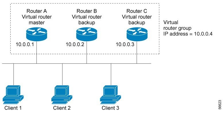
Because the virtual router uses the IP address of the physical Ethernet interface of Router A, Router A assumes the role of the virtual router master and is also known as the IP address owner. As the virtual router master, Router A controls the IP address of the virtual router and is responsible for forwarding packets sent to this IP address. Clients 1 through 3 are configured with the default gateway IP address of 10.0.0.1.
Routers B and C function as virtual router backups. If the virtual router master fails, the router configured with the higher priority will become the virtual router master and provide uninterrupted service for the LAN hosts. When Router A recovers, it becomes the virtual router master again. For more detail on the roles that VRRP routers play and what happens if the virtual router master fails, see the VRRP Router Priority and Preemption section.
The figure below shows a LAN topology in which VRRP is configured so that Routers A and B share the traffic to and from clients 1 through 4 and that Routers A and B act as virtual router backups to each other if either router fails.
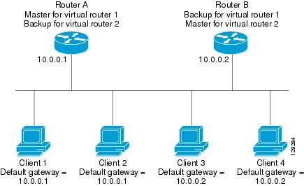
In this topology, two virtual routers are configured. (For more information, see the Multiple Virtual Router Support section.) For virtual router 1, Router A is the owner of IP address 10.0.0.1 and virtual router master, and Router B is the virtual router backup to Router A. Clients 1 and 2 are configured with the default gateway IP address of 10.0.0.1.
For virtual router 2, Router B is the owner of IP address 10.0.0.2 and virtual router master, and Router A is the virtual router backup to Router B. Clients 3 and 4 are configured with the default gateway IP address of 10.0.0.2.
VRRP Benefits
Redundancy
VRRP enables you to configure multiple routers as the default gateway router, which reduces the possibility of a single point of failure in a network.
Load Sharing
You can configure VRRP in such a way that traffic to and from LAN clients can be shared by multiple routers, thereby sharing the traffic load more equitably among available routers.
Multiple Virtual Routers
VRRP supports up to 255 virtual routers (VRRP groups) on a router and up to four virtual routers on every interface, subject to the platform supporting multiple MAC addresses. Multiple virtual router support enables you to implement redundancy and load sharing in your LAN topology.
Multiple IP Addresses
The virtual router can manage multiple IP addresses, including secondary IP addresses. Therefore, if you have multiple subnets configured on an Ethernet interface, you can configure VRRP on each subnet.
Preemption
The redundancy scheme of VRRP enables you to preempt a virtual router backup that has taken over for a failing virtual router master with a higher priority virtual router backup that has become available.
Authentication
VRRP message digest 5 (MD5) algorithm authentication protects against VRRP-spoofing software and uses the industry-standard MD5 algorithm for improved reliability and security.
Advertisement Protocol
VRRP uses a dedicated Internet Assigned Numbers Authority (IANA) standard multicast address (224.0.0.18) for VRRP advertisements. This addressing scheme minimizes the number of routers that must service the multicasts and allows test equipment to accurately identify VRRP packets on a segment. The IANA assigned VRRP the IP protocol number 112.
VRRP Object Tracking
VRRP object tracking provides a way to ensure the best VRRP router is the virtual router master for the group by altering VRRP priorities to the status of tracked objects such as the interface or IP route states.
Multiple Virtual Router Support
You can configure up to 255 virtual routers on a router and up to four virtual routers on every interface. The actual number of virtual routers that a router can support depends on the following factors:
-
Router processing capability
-
Router memory capability
-
Router interface support of multiple MAC addresses
In a topology where multiple virtual routers are configured on a router interface, the interface can act as a master for one virtual router and as a backup for one or more virtual routers.
VRRP Router Priority and Preemption
An important aspect of the VRRP redundancy scheme is VRRP router priority. Priority determines the role that each VRRP router plays and what happens if the virtual router master fails.
If a VRRP router owns the IP address of the virtual router and the IP address of the physical interface, this router will function as a virtual router master.
Priority also determines if a VRRP router functions as a virtual router backup and the order of ascendancy to becoming a virtual router master if the virtual router master fails. You can configure the priority of each virtual router backup with a value of 1 through 254 using the vrrp priority command.
For example, if Router A, the virtual router master in a LAN topology, fails, an election process takes place to determine if virtual router backups B or C should take over. If Routers B and C are configured with the priorities of 101 and 100, respectively, Router B is elected to become virtual router master because it has the higher priority. If Routers B and C are both configured with the priority of 100, the virtual router backup with the higher IP address is elected to become the virtual router master.
By default, a preemptive scheme is enabled whereby a higher priority virtual router backup that becomes available takes over for the virtual router backup that was elected to become virtual router master. You can disable this preemptive scheme using the no vrrp preempt command. If preemption is disabled, the virtual router backup that is elected to become virtual router master remains the master until the original virtual router master recovers and becomes master again.
VRRP Advertisements
The virtual router master sends VRRP advertisements to other VRRP routers in the same group. The advertisements communicate the priority and state of the virtual router master. The VRRP advertisements are encapsulated in IP packets and sent to the IP Version 4 multicast address assigned to the VRRP group. The advertisements are sent every second by default; the interval is configurable.
Although the VRRP protocol as per RFC 3768 does not support millisecond timers, Cisco routers allow you to configure millisecond timers. You need to manually configure the millisecond timer values on both the primary and the backup routers. The master advertisement value displayed in the show vrrp command output on the backup routers is always 1 second because the packets on the backup routers do not accept millisecond values.
You must use millisecond timers where absolutely necessary and with careful consideration and testing. Millisecond values work only under favorable circumstances, and you must be aware that the use of the millisecond timer values restricts VRRP operation to Cisco devices only.
 Note | Millisecond timer value is not supported for VRRPv2 on RSP3 Module. |
In Service Software Upgrade--VRRP
Note | This section is not supported for VRRPv2 on ASR 900 RSP3 Module. |
VRRP supports In Service Software Upgrade (ISSU). In Service Software Upgrade (ISSU) allows a high-availability (HA) system to run in stateful switchover (SSO) mode even when different versions of software are running on the active and standby Route Processors (RPs) or line cards.
ISSU provides the ability to upgrade or downgrade from one supported release to another while continuing to forward packets and maintain sessions, thereby reducing planned outage time. The ability to upgrade or downgrade is achieved by running different software versions on the active RP and standby RP for a short period of time to maintain state information between RPs. This feature allows the system to switch over to a secondary RP running upgraded (or downgraded) software and continue forwarding packets without session loss and with minimal or no packet loss. This feature is enabled by default.
For detailed information about ISSU, see the In Service Software Upgrade Process document in the High Availability Configuration Guide.
How to Configure VRRP
- Customizing VRRP
- Enabling VRRP
- Disabling a VRRP Group on an Interface
- Configuring VRRP Text Authentication
- Enabling the Router to Send SNMP VRRP Notifications
Customizing VRRP
Customizing the behavior of VRRP is optional. Be aware that as soon as you enable a VRRP group, that group is operating. It is possible that if you first enable a VRRP group before customizing VRRP, the router could take over control of the group and become the virtual router master before you have finished customizing the feature. Therefore, if you plan to customize VRRP, it is a good idea to do so before enabling VRRP.
1.
enable
2.
configure
terminal
3.
interface
type
number
4.
ip
address
ip-address
mask
5.
vrrp
group
description
text
6.
vrrp
group
priority
level
7.
vrrp
group
preempt [delay
minimum
seconds]
8.
vrrp
group
timers
advertise [sec]
interval
9.
vrrp
group
timers
learn
10.
exit
DETAILED STEPS
Enabling VRRP
1.
enable
2.
configure
terminal
3.
interface
type
number
4.
ip
address
ip-address
mask
5.
vrrp
group
ip
ip-address [secondary]
6.
end
7.
show
vrrp [brief] |
group]
8.
show
vrrp
interface
type
number [brief]
DETAILED STEPS
| Command or Action | Purpose | |||
|---|---|---|---|---|
| Step 1 |
enable
Example: Router> enable |
Enables privileged EXEC mode. | ||
| Step 2 |
configure
terminal
Example: Router# configure terminal |
Enters global configuration mode. | ||
| Step 3 |
interface
type
number
Example: Router(config)# interface GigabitEthernet 0/0/0 |
Enters interface configuration mode. | ||
| Step 4 |
ip
address
ip-address
mask
Example: Router(config-if)# ip address 172.16.6.5 255.255.255.0 | Configures an IP address for an interface. | ||
| Step 5 |
vrrp
group
ip
ip-address [secondary]
Example: Router(config-if)# vrrp 10 ip 172.16.6.1 |
Enables VRRP on an interface.
| ||
| Step 6 |
end
Example: Router(config-if)# end |
Returns to privileged EXEC mode. | ||
| Step 7 |
show
vrrp [brief] |
group]
Example: Router# show vrrp 10 |
(Optional) Displays a brief or detailed status of one or all VRRP groups on the router. | ||
| Step 8 |
show
vrrp
interface
type
number [brief]
Example: Router# show vrrp interface GigabitEthernet 0/0/0 |
(Optional) Displays the VRRP groups and their status on a specified interface. |
Disabling a VRRP Group on an Interface
Disabling a VRRP group on an interface allows the protocol to be disabled, but the configuration to be retained. This ability was added with the introduction of the VRRP MIB, RFC 2787, Definitions of Managed Objects for the Virtual Router Redundancy Protocol .
You can use a Simple Network Management Protocol (SNMP) management tool to enable or disable VRRP on an interface. Because of the SNMP management capability, the vrrp shutdown command was introduced to represent a method via the command line interface (CLI) for VRRP to show the state that had been configured using SNMP.
When the show running-config command is entered, you can see immediately if the VRRP group has been configured and set to enabled or disabled. This is the same functionality that is enabled within the MIB.
The no form of the command enables the same operation that is performed within the MIB. If the vrrp shutdown command is specified using the SNMP interface, then entering the no vrrp shutdown command reenables the VRRP group.
1.
enable
2.
configure
terminal
3.
interface
type
number
4.
ip
address
ip-address
mask
5.
vrrp
group
shutdown
DETAILED STEPS
| Command or Action | Purpose | |||
|---|---|---|---|---|
| Step 1 |
enable
Example: Router> enable |
Enables privileged EXEC mode. | ||
| Step 2 |
configure
terminal
Example: Router# configure terminal |
Enters global configuration mode. | ||
| Step 3 |
interface
type
number
Example: Router(config)# interface GigabitEthernet0/0/0 |
Enters interface configuration mode. | ||
| Step 4 |
ip
address
ip-address
mask
Example: Router(config-if)# ip address 172.16.6.5 255.255.255.0 | Configures an IP address for an interface. | ||
| Step 5 |
vrrp
group
shutdown
Example: Router(config-if)# vrrp 10 shutdown |
Disables the VRRP group on an interface.
|
Configuring VRRP Text Authentication
Interoperability with vendors that may have implemented the RFC 2338 method is not enabled.
Text authentication cannot be combined with MD5 authentication for a VRRP group at any one time. When MD5 authentication is configured, the text authentication field in VRRP hello messages is set to all zeros on transmit and ignored on receipt, provided the receiving router also has MD5 authentication enabled.
1.
enable
2.
configure
terminal
3.
terminal
interface
type
number
4.
ip
address
ip-address
mask [secondary]
5.
vrrp
group
authentication
text
text-string
6.
vrrp
group
ip
ip-address
7. Repeat Steps 1 through 6 on each router that will communicate.
8.
end
DETAILED STEPS
| Command or Action | Purpose | |||
|---|---|---|---|---|
| Step 1 |
enable
Example: Router> enable |
Enables privileged EXEC mode. | ||
| Step 2 |
configure
terminal
Example: Router# configure terminal |
Enters global configuration mode. | ||
| Step 3 |
terminal
interface
type
number
Example: Router(config)# interface Ethernet 0/1 |
Configures an interface type and enters interface configuration mode. | ||
| Step 4 |
ip
address
ip-address
mask [secondary]
Example: Router(config-if)# ip address 10.0.0.1 255.255.255.0 |
Specifies a primary or secondary IP address for an interface. | ||
| Step 5 |
vrrp
group
authentication
text
text-string
Example: Router(config-if)# vrrp 1 authentication text textstring1 |
Authenticates VRRP packets received from other routers in the group.
| ||
| Step 6 |
vrrp
group
ip
ip-address
Example: Router(config-if)# vrrp 1 ip 10.0.1.20 |
Enables VRRP on an interface and identifies the IP address of the virtual router. | ||
| Step 7 | Repeat Steps 1 through 6 on each router that will communicate. |
— | ||
| Step 8 |
end
Example: Router(config-if)# end |
Returns to privileged EXEC mode. |
Enabling the Router to Send SNMP VRRP Notifications
The VRRP MIB supports SNMP Get operations, which allow network devices to get reports about VRRP groups in a network from the network management station.
Enabling VRRP MIB trap support is performed through the CLI, and the MIB is used for getting the reports. A trap notifies the network management station when a router becomes a Master or backup router. When an entry is configured from the CLI, the RowStatus for that group in the MIB immediately goes to the active state.
1.
enable
2.
configure
terminal
3.
snmp-server
enable
traps
vrrp
4.
snmp-server
host
host
community-string
vrrp
DETAILED STEPS
| Command or Action | Purpose | |
|---|---|---|
| Step 1 |
enable
Example: Router> enable |
Enables privileged EXEC mode.
|
| Step 2 |
configure
terminal
Example: Router# configure terminal |
Enters global configuration mode. |
| Step 3 |
snmp-server
enable
traps
vrrp
Example: Router(config)# snmp-server enable traps vrrp |
Enables the router to send SNMP VRRP notifications (traps and informs). |
| Step 4 |
snmp-server
host
host
community-string
vrrp
Example: Router(config)# snmp-server host myhost.comp.com public vrrp |
Specifies the recipient of an SNMP notification operation. |
Configuration Examples for VRRP
- Example: Configuring VRRP
- Example: VRRP Text Authentication
- Example: Disabling a VRRP Group on an Interface
- Example: VRRP MIB Trap
Example: Configuring VRRP
In the following example, Router A and Router B each belong to three VRRP groups.
In the configuration, each group has the following properties:
Router A
Router(config)# interface GigabitEthernet 1/0/0 Router(config-if)# ip address 10.1.0.2 255.0.0.0 Router(config-if)# vrrp 1 priority 120 Router(config-if)# vrrp 1 authentication cisco Router(config-if)# vrrp 1 timers advertise 3 Router(config-if)# vrrp 1 timers learn Router(config-if)# vrrp 1 ip 10.1.0.10 Router(config-if)# vrrp 5 priority 100 Router(config-if)# vrrp 5 timers advertise 30 Router(config-if)# vrrp 5 timers learn Router(config-if)# vrrp 5 ip 10.1.0.50 Router(config-if)# vrrp 100 timers learn Router(config-if)# no vrrp 100 preempt Router(config-if)# vrrp 100 ip 10.1.0.100 Router(config-if)# no shutdown
Router B
Router(config)# interface GigabitEthernet 1/0/0 Router(config-if)# ip address 10.1.0.1 255.0.0.0 Router(config-if)# vrrp 1 priority 100 Router(config-if)# vrrp 1 authentication cisco Router(config-if)# vrrp 1 timers advertise 3 Router(config-if)# vrrp 1 timers learn Router(config-if)# vrrp 1 ip 10.1.0.10 Router(config-if)# vrrp 5 priority 200 Router(config-if)# vrrp 5 timers advertise 30 Router(config-if)# vrrp 5 timers learn Router(config-if)# vrrp 5 ip 10.1.0.50 Router(config-if)# vrrp 100 timers learn Router(config-if)# no vrrp 100 preempt Router(config-if)# vrrp 100 ip 10.1.0.100 Router(config-if)# no shutdown
Example: VRRP Text Authentication
The following example shows how to configure VRRP text authentication using a text string:
Router(config)# interface GigabitEthernet 0/0/0 Router(config)# ip address 10.21.8.32 255.255.255.0 Router(config-if)# vrrp 10 authentication text stringxyz Router(config-if)# vrrp 10 ip 10.21.8.10
Example: Disabling a VRRP Group on an Interface
The following example shows how to disable one VRRP group on GigabitEthernet interface 0/0/0 while retaining VRRP for group 2 on GigabitEthernet interface 1/0/0:
Router(config)# interface GigabitEthernet 0/0/0 Router(config-if)# ip address 10.24.1.1 255.255.255.0 Router(config-if)# vrrp 1 ip 10.24.1.254 Router(config-if)# vrrp 1 shutdown Router(config-if)# exit Router(config)# interface GigabitEthernet 1/0/0 Router(config-if)# ip address 10.168.42.1 255.255.255.0 Router(config-if)# vrrp 2 ip 10.168.42.254
Example: VRRP MIB Trap
Router(config)# snmp-server enable traps vrrp Router(config)# snmp-server host 10.1.1.0 community abc vrrp
 Feedback