MPLS Basic Configuration Guide (ASR 900 Series)
Bias-Free Language
The documentation set for this product strives to use bias-free language. For the purposes of this documentation set, bias-free is defined as language that does not imply discrimination based on age, disability, gender, racial identity, ethnic identity, sexual orientation, socioeconomic status, and intersectionality. Exceptions may be present in the documentation due to language that is hardcoded in the user interfaces of the product software, language used based on RFP documentation, or language that is used by a referenced third-party product. Learn more about how Cisco is using Inclusive Language.
- Updated:
- March 27, 2015
Chapter: Circuit Emulation Service over UDP
Circuit Emulation Service
over UDP
 Note | This chapter is not applicable on the ASR 900 RSP3 Module for the Cisco IOS XE Release 3.16. |
The Circuit Emulation Service over UDP (CEMoUDP) feature extends the implementation of Cisco IOS Circuit Emulation Service (CES) by supporting pseudowire emulation (PWE) function to be performed over an Internet Protocol (IP) network directly.
As part of CEMoUDP, both Circuit Emulation Service over Packet-Switched Network (CESoPSN) and Structure-agnostic TDM over Packet (SAToP) are supported. CESoPSN is supported
CEMoUDP is supported on 8T1/E1 interface module, 16T1/E1 interface module, 32T1/E1, and OC3 interface module on the router.
- Finding Feature Information
- Restrictions for Circuit Emulation Service over UDP
- Information About Circuit Emulation Service over UDP
Finding Feature Information
Your software release may not support all the features documented in this module. For the latest caveats and feature information, see Bug Search Tool and the release notes for your platform and software release. To find information about the features documented in this module, and to see a list of the releases in which each feature is supported, see the feature information table.
Use Cisco Feature Navigator to find information about platform support and Cisco software image support. To access Cisco Feature Navigator, go to www.cisco.com/go/cfn. An account on Cisco.com is not required.
Restrictions for Circuit Emulation Service over UDP
-
Because CLI on Route Processor (RP) is used to install the Access Control List (ACL) entry, the ACL programming is decoupled from the Layer 2 virtual private network (L2VPN) control plane update. As a result, when a pseudowire circuit goes down, the ACL is still present. Any traffic coming in from the core which matches the ACL is redirected to the egress line card, where it is dropped due to the absence of appropriate entries in the disposition table.
-
Pseudowires redundancy is not supported.
-
Fragmentation of IP packets is not supported. The Don’t Fragment (DF) bit is set when the IP header is inserted.
-
Path MTU is not supported.
-
Differential synchronization mode is not supported.
-
The optional Real-Time Protocol (RTP) header is not supported on CEMoUDP.
-
The Time To Live (TTL) value in the IP header is configurable under the pseudowire class. The default value is 255.
-
Adaptive Clock Recovery is not supported.
Restrictions for Circuit Emulation Service over UDP on the Cisco ASR 900 Series Routers
-
The following are the only application protocols with same loopback as used by CEM over UDP that are supported on router:
Note | The interfaces on the chassis may not work when cemoudp reserve bay configuration is unconfigured. The CEM data sent by the peer may hog the CPU. We recommend to shutdown the core links connecting the PE routers and add the configurations on the loopback interface. |
Information About Circuit Emulation Service over UDP
- CES Overview
- Pseudowire Emulation over Packet
- Circuit Emulation Services over Packet Switched Network over UDP
- Structure-Agnostic TDM over Packet over UDP
CES Overview
Circuit Emulation Service—Internetworking Function (CES-IWF) is a service based on ATM forum standards that allows communications to occur between Constant Bit Rate (CBR) or AAL1 CES and ATM User Network Interfaces (UNI); that is, between non-ATM telephony devices (such as classic private branch exchange (PBX) or Time Division Multiplexing (TDM) and ATM devices.
CES allows you to interconnect existing T1 or E1 interfaces and other kinds of CBR equipment. CES includes features such as PBX interconnect, consolidated voice and data traffic, and video conferencing.
With circuit emulation, data received from an external device at the edge of an ATM network is converted to ATM cells, sent through the network, reassembled into a bit stream, and passed out of the ATM network to its destination. T1/E1 circuit emulation does not interpret the contents of the data stream. All the bits flowing into the input edge port of the ATM network are reproduced at one corresponding output edge port.
An emulated circuit is carried across the ATM network on a PVC, which is configured through the network management system or the router command line interface (CLI).
Pseudowire Emulation over Packet
Pseudowire Emulation over Packet (PWEoP) is one of the key components that you can use to migrate to a packet-based multi-service network. Circuit Emulation over Packet (CEoP) is a subset of PWEoP. It is used to migrate to all-packet networks from legacy TDM networks, yet providing transport for legacy applications transparently over a packet network. CEoP is the imitation of a physical connection. Many service providers and enterprises operate both packet switched networks and TDM networks. These service providers and enterprises have moved many of their data services from the TDM network to their packet network for scalability and efficiency. Cisco provides routing and switching solutions capable of transporting Layer 2 and Layer 3 protocols such as Ethernet, IP, and Frame Relay. Most applications and services have been migrated to the packet-based network, including voice and legacy applications.
Circuit Emulation Services over Packet Switched Network over UDP
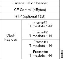
CESoPSN mode is used to encapsulate T1/E1 structured (channelized) services over PSN. Also referred to as structured mode, CESoPSN identifies framing and sends only payload, which can be channelized T1s within DS3 and DS0s within T1. DS0s can be bundled to the same packet. This mode is based on IETF RFC 5086.
UDP acts as transport mechanism over IP for CESoPSN.
Each supported interface can be configured individually to any supported mode. The supported services comply with IETF and ITU drafts and standards.
The figure below shows the frame format in CESoPSN mode.
How to Configure Circuit Emulation Service over UDP
Perform the following task to configure Circuit Emulation Service over UDP:
1.
enable
2.
configure
terminal
3.
interface
loopback
interface-number
4.
ip
address
ip-address
mask
[secondary]
5.
cemoudp
reserve
bay
bay-number
6.
pseudowire-class
pseudowire-class-name
7.
encapsulation
udp
8.
ip
local
interface
loopback
interface-number
9.
ip
tos
value
number
10.
ip
ttl
number
11.
exit
12.
controller
{e1 | t1}
slot
/
subslot
/
port
13.
clock
source
{internal |
line
|
loop}
14.
cem-group
number
timeslots
number
15.
exit
16.
interface
cem
slot
/
subslot
/
port
17.
cem
group-number
18.
xconnect
peer-router-id
vcid
pw-class
name
19.
udp
port
local
local-udp-port
remote
remote-udp-port
20.
exit
DETAILED STEPS
Configuration Examples for Circuit Emulation Service over UDP
- Example Configuring Circuit Emulation Service over UDP
- Example Verifying the Configuration of Circuit Emulation Service over UDP
Example Configuring Circuit Emulation Service over UDP
Router> enable
Router# configure terminal
Router(config)# interface loopback 0
Router(config-if)# ip address 10.2.2.8 255.255.255.255
Router(config-if)# cemoudp reserve bay 2
Router(config)# pseudowire-class udpClass
Router(config-pw-class)# encapsulation udp
Router(config-pw-class)# ip local interface loopback 0
Router(config-pw-class)# ip tos value 100
Router(config-pw-class)# ip ttl 100
Router(config-pw-class)# exit
Router(config)# controller T1 0/2/8
Router(config-controller)# clock source internal
Router(config-controller)# cem-group 5 timeslots 1-24
Router(config-controller)# exit
Router(config)# interface cem 2/0/0
Router(config-if)# cem 5
Router(config-if-cem)# xconnect 10.30.30.2 305 pw-class udpClass
Router(config-if-cem)# udp port local 50000 remote 55000
Router(config-if-cem)# exit
Example Verifying the Configuration of Circuit Emulation Service over UDP
Router# show xconnect all
Legend:    XC ST=Xconnect State  S1=Segment1 State  S2=Segment2 State
  UP=Up       DN=Down            AD=Admin Down      IA=Inactive
  SB=Standby  HS=Hot Standby     RV=Recovering      NH=No Hardware

XC ST  Segment 1                         S1 Segment 2                         S2
------+---------------------------------+--+---------------------------------+--
UP     ac   CE3/0/0:1(CESoPSN Basic)     UP udp  66.66.66.66:180              UP
UP     ac   CE3/0/0:6(CESoPSN Basic)     UP udp  66.66.66.66:181              UP

Router# show pw-udp vc
Local intf     Local circuit              VC ID      Status
-------------- -------------------------- ---------- --------
CE3/0/0        CESoPSN Basic              180        established
  LAddr: 55.55.55.55     LPort: 50002
  RAddr: 66.66.66.66     RPort: 50002
CE3/0/0        CESoPSN Basic              181        established
  LAddr: 55.55.55.55     LPort: 50004
  RAddr: 66.66.66.66     RPort: 50004
Structure-Agnostic TDM over Packet over UDP
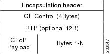
Structure-Agnostic TDM over Packet (SAToP) encapsulates time division multiplexing (TDM) bit-streams (T1, E1, T3, E3) as PWs over public switched networks. It disregards any structure that may be imposed on streams, in particular the structure imposed by the standard TDM framing.
The protocol used for emulation of these services does not depend on the method in which attachment circuits are delivered to the provider edge (PE) devices. For example, a T1 attachment circuit is treated the same way for all delivery methods, including copper, multiplex in a T3 circuit, a virtual tributary of a SONET/SDH circuit, or unstructured Circuit Emulation Service (CES).
In SAToP mode the interface is considered as a continuous framed bit stream. The packetization of the stream is done according to IETF RFC 4553. All signaling is carried out transparently as a part of a bit stream. The following figure shows the frame format in Unstructured SAToP mode.
| Maximum Payload | Maximum Jitter | Minimum Jitter | Minimum Payload | Maximum Jitter | Minimum Jitter |
| 960 | 320 | 10 | 192 | 64 | 2 |
| Maximum Payload | Maximum Jitter | Minimum Jitter | Minimum Payload | Maximum Jitter | Minimum Jitter |
| 1280 | 320 | 10 | 256 | 64 | 2 |
- How to Configure Structure-Agnostic TDM over Packet
- Configuration Examples for Structure-Agnostic TDM over Packet
How to Configure Structure-Agnostic TDM over Packet
Perform the following task to configure Structure-Agnostic TDM over Packet (SAToP):
1.
enable
2.
configure
terminal
3.
interface
loopback
interface-number
4.
ip
address
ip-address
mask
[secondary]
5.
cemoudp
reserve
bay
bay-number
6.
pseudowire-class
pseudowire-class-name
7.
encapsulation
udp
8.
ip
local
interface
loopback
interface-number
9.
ip
tos
value
number
10.
ip
ttl
number
11.
exit
12.
controller
{e1 | t1}
slot
/
subslot
/
port
13.
clock
source
{internal |
line
|
loop}
14.
framing
number
{esf |
sf |
crc4 |
no-crc4 |
unframed}
15.
cem-group
number
unframed
16.
exit
17.
interface
cem
slot
/
subslot
/
port
18.
cem
group-number
19.
xconnect
peer-router-id
vcid
pw-class
name
20.
udp
port
local
local-udp-port
remote
remote-udp-port
21.
exit
DETAILED STEPS
| Command or Action | Purpose | |||
|---|---|---|---|---|
| Step 1 |
enable
Example: Router> enable |
Enables privileged EXEC mode. | ||
| Step 2 |
configure
terminal
Example: Router# configure terminal |
Enters global configuration mode. | ||
| Step 3 |
interface
loopback
interface-number
Example: Router(config)# interface loopback 1 |
Enables the loopback interface and enters interface configuration mode. | ||
| Step 4 |
ip
address
ip-address
mask
[secondary]
Example: Router(config)# ip address 10.1.1.1 255.255.255.255 |
Specifies the IP address and subnet mask for this loopback interface. | ||
| Step 5 |
cemoudp
reserve
bay
bay-number
Example: Router(config-if)# cemoudp reserve bay 1 |
Reserves a loopback interface used as source for the CESoPSN circuit. | ||
| Step 6 |
pseudowire-class
pseudowire-class-name
Example: Router(config-if)# psuedowire-class PS1 |
Creates a new pseudowire class and enters pseudowire-class configuration mode. | ||
| Step 7 |
encapsulation
udp
Example: Router(config-pw-class)# encapsulation udp |
Specifies the UDP transport protocol. | ||
| Step 8 |
ip
local
interface
loopback
interface-number
Example: Router(config-pw-class)# ip local interface loopback 1 |
Configures the IP address of the provider edge (PE) router interface as the source IP address for sending tunneled packets. | ||
| Step 9 |
ip
tos
value
number
Example: Router(config-pw-router)# ip tos value 23 |
Specifies the type of service (ToS) level for IP traffic in the pseudowire. | ||
| Step 10 |
ip
ttl
number
Example: Router(config-pw-class)# ip ttl 32 |
| ||
| Step 11 |
exit
Example: Router(config-pw-class)# exit |
Exits pseudowire-class configuration mode. | ||
| Step 12 |
controller
{e1 | t1}
slot
/
subslot
/
port
Example: Router(config)# controller e1 0/1/8 |
Enters E1/T1 controller configuration mode. | ||
| Step 13 |
clock
source
{internal |
line
|
loop}
Example: Router(config-controller)# clock source internal |
Enters controller configuration mode and sets the clock source on the interface to:
| ||
| Step 14 |
framing
number
{esf |
sf |
crc4 |
no-crc4 |
unframed}
Example: Router(config-controller)# framing unframed |
Use the framed keyword to specify Extended Superframe or Superframe framing. Use the unframed keyword to specify that a single CEM channel is being created including all time slots and the framing structure of the line.
| ||
| Step 15 |
cem-group
number
unframed
Example: Router(config-controller)# cem-group 5 unframed | Assigns channels on the T1/E1 circuit to the circuit emulation (CEM) channel. | ||
| Step 16 |
exit
Example: Router(config-controller)# exit |
Exits controller configuration. | ||
| Step 17 |
interface
cem
slot
/
subslot
/
port
Example:
Router(config)# interface cem 0/2/8 |
Selects the CEM interface where the CEM circuit (group) is located (where slot/subslot is the SPA slot and subslot and port is the SPA port where the interface exists) and enters CEM interface mode. | ||
| Step 18 |
cem
group-number
Example: Router(config-if-cem)# cem 5 |
Defines a CEM channel. | ||
| Step 19 |
xconnect
peer-router-id
vcid
pw-class
name
Example:
Router(config-if-cem)# xconnect 10.30.30.1 12 pw-class PS1
|
Binds an attachment circuit to the CEM interface to create a pseudowire. This example creates a pseudowire by binding the CEM circuit 5 to the remote peer 30.30.30.2.
| ||
| Step 20 |
udp
port
local
local-udp-port
remote
remote-udp-port
Example: Router(config-if-cem)# udp port local 49154 remote 50201 |
Specifies a local and remote UDP port for the connection. | ||
| Step 21 |
exit
Example: Router(config-if-cem)# exit |
Exits the CEM interface. |
Configuration Examples for Structure-Agnostic TDM over Packet
Example Configuring Structure-Agnostic TDM over Packet
Router> enable
Router# configure terminal
Router(config)# interface loopback 0
Router(config-if)# ip address 11.11.11.11 255.255.255.255
Router(config-if)# cemoudp reserve bay 0
Router(config)# pseudowire-class udp
Router(config-pw-class)# encapsulation udp
Router(config-pw-class)# ip local interface loopback 0
Router(config-pw-class)# ip tos value 100
Router(config-pw-class)# ip ttl 100
Router(config-pw-class)# exit
Router(config)# controller t1 0/0/3
Router(config-controller)# clock source internal
Router(config-controller)# cem-group 0 unframed
Router(config-controller)# exit
Router(config)#  interface cem 0/0/3
Router(config-if)# cem 0
Router(config-if-cem)# xconnect 22.22.22.22 1000 pw-class UDP
Router(config-if-cem)# udp port local 49800 remote 49800
Router(config-if-cem)# exit
Example Verifying the Configuration of Structure-Agnostic TDM over Packet
Router# show xconnect all
Legend:    XC ST=Xconnect State  S1=Segment1 State  S2=Segment2 State
  UP=Up       DN=Down            AD=Admin Down      IA=Inactive
  SB=Standby  HS=Hot Standby     RV=Recovering      NH=No Hardware

XC ST  Segment 1                         S1 Segment 2                         S2
------+---------------------------------+--+---------------------------------+--
UP pri   ac CE0/0/3:0(SATOP T1)          UP  udp 22.22.22.22:1000             UP


Router# show pw-udp vc
Local intf        Local circuit              VC ID      Status
----------------- -------------------------- ---------- ---------------
CE0/0/3           SATOP T1                   1000       established
  LAddr: 11.11.11.11     LPort: 49800
  RAddr: 22.22.22.22     RPort: 49800
 Feedback