The documentation set for this product strives to use bias-free language. For the purposes of this documentation set, bias-free is defined as language that does not imply discrimination based on age, disability, gender, racial identity, ethnic identity, sexual orientation, socioeconomic status, and intersectionality. Exceptions may be present in the documentation due to language that is hardcoded in the user interfaces of the product software, language used based on RFP documentation, or language that is used by a referenced third-party product. Learn more about how Cisco is using Inclusive Language.
Interworking is a transforming function that is required to interconnect two heterogeneous attachment circuits (ACs). Several
types of interworking functions exist. The function that is used would depend on the type of ACs being used, the type of data
being carried, and the level of functionality required. The two main Layer 2 Virtual Private Network (L2VPN) interworking
functions supported in Cisco IOS XE software are bridged and routed interworking.
Layer 2 (L2) transport over multiprotocol label switching (MPLS) and IP already exists for like-to-like ACs, such as Ethernet-to-Ethernet
or Point-to-Point Protocol (PPP)-to-PPP. L2VPN Interworking builds on this functionality by allowing disparate ACs to be connected.
An interworking function facilitates the translation between different L2 encapsulations.
Finding Feature Information
Your software release may not support all the features documented in this module. For the latest caveats and feature information,
see Bug Search Tool and the release notes for your platform and software release. To find information about the features documented in this module,
and to see a list of the releases in which each feature is supported, see the feature information table.
Use Cisco Feature Navigator to find information about platform support and Cisco software image support. To access Cisco Feature
Navigator, go to www.cisco.com/go/cfn. An account on Cisco.com is not required.
Prerequisites for L2VPN
Interworking
Before you configure
L2VPN interworking on a device you must enable Cisco Express Forwarding.
HDLC-to-Ethernet
Interworking
Ensure that the
serial controller and interface on the High-Level Data Link Control (HDLC)
customer edge (CE) and provider edge (PE) devices are configured.
enable
 configure terminal
  controller e1 2/0
   channel-group 0 timeslots 1
   no shutdown
!
interface Serial 2/0:0
 no shutdown
end
Before
configuring HDLC-to-Ethernet bridged interworking, ensure that bridging is
configured on the HDLC CE device.
enable
 configure terminal
  bridge irb
  bridge 1 protocol ieee
  bridge 1 route ip
!
interface Serial 2/0:0
 no bridge-group 1
 no ip address
!
interface BVI1
 no ip address
 ip address 192.0.2.1 255.255.255.0
 no shutdown
!
interface Serial 2/0:0
 no ip address
 encapsulation hdlc
 bridge-group 1
  no shutdown
end
Before
configuring HDLC-to-Ethernet routed interworking, ensure that an IP address is
configured on the HDLC CE device.
interface Serial 2/0:0
 ip address 192.0.2.1 255.255.255.0
 encapsulation hdlc
 no shutdown
end
Restrictions for L2VPN Interworking
General Restrictions for
L2VPN Interworking
This section lists general restrictions that apply to L2VPN interworking. Other restrictions that are platform-specific or
device-specific are listed in the following sections.
MTU configured on
the AC should not exceed the MTU in the core of the network because
fragmentation is not supported.
The interworking type on one provider edge (PE) router must match the interworking type on the peer PE router.
IP interworking
with native VLANs is not supported.
Ethernet VLAN (Type 4) interworking is not supported.
Only the following Quality of Service (QoS) features are supported with L2VPN interworking:
Static IP type of service (ToS) or MPLS experimental bit (EXP) setting in tunnel header.
One-to-one mapping of VLAN priority bits to MPLS EXP bits.
VRF-aware Layer 2 Tunneling Protocol Version 3 (L2TPv3) is not supported on Cisco ASR 1000 platforms.
Restrictions for Routed
Interworking
Routed interworking
has the following restrictions:
Multipoint Frame
Relay (FR) is not supported.
QoS
classification on IP ToS, DSCP and other IP header fields is not supported.
Security access
control list (ACL) and other features based on IP header fields parsing are not
supported.
In routed mode,
only one customer edge (CE) router can be attached to an Ethernet PE router.
There must be a
one-to-one relationship between an AC and the pseudowire. Point-to-multipoint
or multipoint-to-point configurations are not supported.
You must
configure routing protocols for point-to-point operation on the CE routers when
configuring an Ethernet to non-Ethernet setup.
In the IP
interworking mode, the IPv4 (0800) translation is supported. The PE router
captures Address Resolution Protocol (ARP) (0806) packets and responds with its
own MAC address (proxy ARP). Everything else is dropped.
The Ethernet must
contain only two IP devices: PE router and CE router. The PE router performs
proxy ARP and responds to all ARP requests it receives. Therefore, only one CE
router and one PE router should be on the Ethernet segment.
If the CE routers
are doing static routing, you can perform the following tasks:
The PE router
needs to learn the MAC address of the CE router to correctly forward traffic to
it. The Ethernet PE router sends an Internet Control Message Protocol (ICMP)
Router Discovery Protocol (RDP) solicitation message with the source IP address
as zero. The Ethernet CE router responds to this solicitation message. To
configure the Cisco CE router’s Ethernet interface to respond to the ICMP RDP
solicitation message, issue the
ip irdp command in interface configuration mode. If
you do not configure the CE router, traffic is dropped until the CE router
sends traffic toward the PE router.
To disable the
CE routers from running the router discovery protocol, issue the
ip irdp maxadvertinterval 0 command in interface configuration mode.
When you change
the interworking configuration on an Ethernet PE router, clear the ARP entry on
the adjacent CE router so that it can learn the new MAC address. Otherwise, you
might experience traffic drops.
Restrictions for PPP
Interworking
The following
restrictions apply to PPP interworking:
There must be a
one-to-one relationship between a PPP session and the pseudowire. Multiplexing
of multiple PPP sessions over the pseudowire is not supported.
Only IP (IPv4
(0021) interworking is supported. Link Control Protocol (LCP) packets and
Internet Protocol Control Protocol (IPCP) packets are terminated at the PE
router. Everything else is dropped.
By default, the
PE router assumes that the CE router knows the remote CE router’s IP address.
Password
Authentication Protocol (PAP) and Challenge-Handshake Authentication Protocol
(CHAP) authentication are supported.
Restrictions for
Ethernet/VLAN-to-ATM AAL5 Interworking
The Ethernet/VLAN to
ATM AAL5 Any Transport over MPLS (AToM) has the following restrictions:
Only the
following translations are supported; other translations are dropped:
Ethernet without LAN FCS
(AAAA030080C200070000)
Spanning tree
(AAAA030080C2000E)
The ATM
encapsulation type supported for bridged interworking is aal5snap. However, ATM
encapsulation types supported for routed interworking are aal5snap and aal5mux.
The existing QoS
functionality for ATM is supported, including setting the ATM CLP bit.
Only ATM AAL5 VC
mode is supported. ATM VP and port mode are not supported.
SVCs are not
supported.
Individual AAL5
ATM cells are assembled into frames before being sent across the pseudowire.
Non-AAL5 traffic,
(such as Operation, Administration, and Maintenance (OAM) cells) is punted to
be processed at the route processor (RP) level. A VC that has been configured
with OAM cell emulation on the ATM PE router (using the
oam-ac emulation-enable CLI command) can send end-to-end
F5 loopback cells at configured intervals toward the CE router.
When the
pseudowire is down, an F5 end-to-end segment alarm indication signal/remote
defect indication (AIS/RDI) is sent from the PE router to the CE router.
If the Ethernet
frame arriving from the Ethernet CE router includes a 802.1Q header (VLAN
header), due to the type of endpoint attachment (Ethernet port mode), the VLAN
header stays in the frame across the pseudowire (see the figure below).
Figure 1. Protocol Stack for
ATM-to-Ethernet AToM Bridged Interworking--with VLAN Header
Restrictions for
Ethernet/VLAN-to-Frame Relay Interworking
The
Ethernet/VLAN-to-Frame Relay AToM has the following restrictions:
Only the
following translations are supported; other translations are dropped:
Ethernet without LAN FCS
(0300800080C20007)
Spanning tree
(0300800080C2000E)
The PE router
automatically supports translation of both Cisco and IETF Frame Relay
encapsulation types coming from the CE router, but translates only to IETF when
sending to the CE router. This is not a problem for the Cisco CE router,
because it can manage IETF encapsulation upon receipt even if it is configured
to send a Cisco encapsulation.
The PVC status
signaling works the same way as in the like-to-like case. The PE router reports
the PVC status to the CE router based upon the availability of the pseudowire.
The AC maximum
transmission unit (MTU) must be within the supported range of MTUs when
connected over MPLS.
Only Frame Relay
DLCI mode is supported. Frame Relay port mode is not supported.
If the Ethernet
frame includes a 802.1Q header (VLAN header), due to the type of endpoint
attachment (Ethernet port mode), the VLAN header stays in the frame across the
pseudowire (see the figure below).
Frame Relay
encapsulation types supported for routed interworking are Cisco and IETF for
incoming traffic. However, IETF is also supported for outgoing traffic
traveling to the CE router.
Figure 2. Protocol Stack for Frame
Relay-to-Ethernet AToM Bridged Interworking--with VLAN Header
Restrictions for
HDLC-to-Ethernet Interworking
The “none CISCO”
High-Level Data Link Control (HDLC) encapsulation is not supported.
IPv6 is not
supported in routed mode.
Information About L2VPN Interworking
Overview of L2VPN
Interworking
L2 transport over
MPLS and IP already exists for like-to-like ACs, such as Ethernet-to-Ethernet
or PPP-to-PPP. L2VPN Interworking builds on this functionality by allowing
disparate ACs to be connected. An interworking function facilitates the
translation between the different L2 encapsulations.
Only the following
interworking combinations are supported:
ATM-to-Ethernet -
Routed interworking
ATM-to-Ethernet -
Bridged interworking
Frame
relay-to-Ethernet - Bridged interworking
PPP-to-Ethernet -
Routed interworking
HDLC-to-Ethernet
- Bridged and Routed interworking
L2VPN Interworking
Modes
L2VPN interworking
works in either Ethernet (bridged) mode or IP (routed) mode. L2VPN interworking
does not support Ethernet VLAN (Type 4) mode. You specify the mode in the
following ways:
If using the older
legacy CLI commands, you can use the
interworking
{ethernet |
ip } command in
pseudowire-class configuration mode.
If using the newer
L2VPN protocol-based CLI commands, you can use the
interworking
{ethernet |
ip } command in
xconnect configuration mode.
The
interworking
command causes the ACs to be terminated locally. The two keywords perform the
following functions:
The
ethernet
keyword causes Ethernet frames to be extracted from the AC and sent over the
pseudowire. Ethernet end-to-end transmission is resumed. AC frames that are not
Ethernet are dropped. In the case of VLAN, the VLAN tag is removed, leaving an
untagged Ethernet frame.
The
ip keyword
causes IP packets to be extracted from the AC and sent over the pseudowire. AC
frames that do not contain IPv4 packets are dropped.
The following
sections explain more about Ethernet and IP interworking modes.
Ethernet or Bridged Interworking
Ethernet interworking is also called bridged interworking. Ethernet frames are bridged across the pseudowire. The CE routers
could be natively bridging Ethernet or could be routing using a bridged encapsulation model, such as Bridge Virtual Interface
(BVI) or Routed Bridge Encapsulation (RBE). The PE routers operate in Ethernet like-to-like mode.
This mode is used to offer the following services:
LAN services--An example is an enterprise that has several sites, where some sites have Ethernet connectivity to the service
provider (SP) network and others have ATM connectivity. If the enterprise wants LAN connectivity to all its sites, traffic
from the Ethernet or VLAN of one site can be sent through the IP/MPLS network and encapsulated as bridged traffic over an
ATM VC of another site.
Connectivity services--An example is an enterprise that has different sites that are running an Internal Gateway Protocol
(IGP) routing protocol, which has incompatible procedures on broadcast and nonbroadcast links. The enterprise has several
sites that are running an IGP, such as Open Shortest Path First (OSPF) or Intermediate System-to-Intermediate System (IS-IS),
between the sites. In this scenario, some of the procedures (such as route advertisement or designated router) depend on the
underlying L2 protocol and are different for a point-to-point ATM connection versus a broadcast Ethernet connection. Therefore,
the bridged encapsulation over ATM can be used to achieve homogenous Ethernet connectivity between the CE routers running
the IGP.
IP or Routed
Interworking
IP interworking is
also called routed interworking. The CE routers encapsulate the IP on the link
between the CE router and PE router. A new VC type is used to signal the IP
pseudowire in MPLS. Translation between the L2 and IP encapsulations across the
pseudowire is required. Special consideration needs to be given to the address
resolution and routing protocol operation, because these are handled
differently on different L2 encapsulations.
This mode is used to
provide IP connectivity between sites, regardless of the L2 connectivity to
these sites. It is different from a Layer 3 VPN because it is point-to-point in
nature and the service provider does not maintain any customer routing
information.
Address resolution is
encapsulation dependent:
Ethernet uses
Address Resolution Protocol (ARP)
ATM uses inverse
ARP
PPP uses IP
Control Protocol (IPCP)
HDLC uses Serial Line ARP (SLARP)
Therefore, address
resolution must be terminated on the PE router. End-to-end address resolution
is not supported. Routing protocols operate differently over broadcast and
point-to-point media. For Ethernet, the CE routers must either use static
routing or configure the routing protocols to treat the Ethernet side as a
point-to-point network.
In routed
interworking, IP packets that are extracted from the ACs are sent over the
pseudowire. The pseudowire works in the IP Layer 2 transport (VC type 0x000B)
like-to-like mode. The interworking function at network service provider’s
(NSP) end performs the required adaptation based on the AC technology. Non-IPv4
packets are dropped.
In routed
interworking, the following considerations are to be kept in mind:
Address
resolution packets (ARP), inverse ARP, and IPCP are punted to the routing
protocol. Therefore, NSP at the PE router must provide the following
functionality for address resolution:
Ethernet--PE device acts as
a proxy-ARP server to all ARP requests from the CE router. The PE router
responds with the MAC address of its local interface.
ATM and Frame Relay
point-to-point--By default, inverse ARP does not run in the point-to-point
Frame Relay or ATM subinterfaces. The IP address and subnet mask define the
connected prefix; therefore, configuration is not required in the CE devices.
Interworking
requires that the MTUs in both ACs match for the pseudowire to come up. The
default MTU in one AC should match with the MTU of other AC. The table below
lists the range of MTUs that can be configured for different ACs.
Table 1. Range of MTUs for Different
ACs
AC type
Range of MTUs
supported
ATM
64 to 17940
Gigabit
Ethernet
1500 to 4470
POS
64to 9102
Fast Ethernet
64to 9192
Note
The MTU configured
on the AC should not exceed the MTU in the core network. This ensures that the
traffic is not fragmented.
The CE routers
with Ethernet attachment VCs running OSPF must be configured with the
ospfIfType option so that the OSPF protocol treats
the underlying physical broadcast link as a P2P link.
Ethernet VLAN-to-ATM AAL5 Interworking
The following topics are covered in this section:
ATM AAL5-to-Ethernet Port AToM--Bridged Interworking
This interworking type provides interoperability between the ATM attachment VC and Ethernet attachment VC connected to different
PE routers. Bridged encapsulation corresponding to the bridged (Ethernet) interworking mechanism is used.
The interworking function is performed at the PE router connected to the ATM attachment VC based on multiprotocol encapsulation
over ATM AAL5 (see the figure below).
Figure 3. Network Topology for ATM-to-Ethernet AToM Bridged Interworking
The advantage of this architecture is that the Ethernet PE router (connected to the Ethernet segment) operates similarly
to Ethernet like-to-like services.
On the PE router with interworking function, in the direction from the ATM segment to MPLS cloud, the bridged encapsulation
(ATM/subnetwork access protocol (SNAP) header) is discarded and the Ethernet frame is encapsulated with the labels required
to go through the pseudowire using the VC type 5 (Ethernet) (see the figure below).
In the opposite direction, after the label disposition from the MPLS cloud, Ethernet frames are encapsulated over AAL5 using
bridged encapsulation.
The figure below shows the protocol stack for ATM-to-Ethernet AToM bridged interworking. The ATM side has an encapsulation
type of aal5snap.
Figure 4. Protocol Stack for ATM-to-Ethernet AToM Bridged Interworking--without VLAN Header
This interworking type provides interoperability between the ATM attachment VC and Ethernet VLAN attachment VC connected
to different PE routers. Bridged encapsulation corresponding to the bridged (Ethernet) interworking mechanism is used.
The interworking function is performed in the same way as for the ATM-to-Ethernet port case, implemented on the PE router
connected to the ATM attachment VC. The implementation is based on multiprotocol encapsulation over ATM AAL5 (see the figure
below).
For the PE router connected to the Ethernet side, one major difference exists due the existence of the VLAN header in the
incoming packet. The PE router discards the VLAN header of the incoming frames from the VLAN CE router, and the PE router
inserts a VLAN header into the Ethernet frames traveling from the MPLS cloud. The frames sent on the pseudowire (with VC type
5) are Ethernet frames without the VLAN header.
Encapsulation over ATM AAL5 is shown in the figure below.
Figure 5. Protocol Stack for ATM -to-VLAN AToM Bridged Interworking
ATM-to-Ethernet--Routed Interworking
To perform routed interworking, both the ATM PE router and Ethernet PE router must be configured. The figure below shows
the routed interworking between ATM to Ethernet. The IP encapsulation over the pseudowire is performed on the ATM packets
arriving from the ATM CE router.
The address resolution is done at the ATM PE router; it is required when the ATM CE router does an inverse ARP. It is not
required when the ATM CE router is configured using Point-to-Point (P2P) subinterfaces or static maps.
When packets arrive from the Ethernet CE router, the Ethernet PE router removes the L2 frame tag, and then forwards the IP
packet to the egress PE router, using IPoMPLS encapsulation over the pseudowire. The Ethernet PE router makes the forwarding
decision based on the L2 circuit ID, the VLAN ID, or port ID, of the incoming L2 frame. At the ATM PE router, after label
disposition, the IP packets are encapsulated over the AAL5 using routed encapsulation based on RFC 2684.
The address resolution at the Ethernet PE router can be done when the Ethernet CE router configures the static ARP, or by
the proxy ARP on the Ethernet PE router. If the proxy ARP is used, the IP address of the remote CE router can be learned dynamically.
Routing protocols need to be configured to operate in the P2P mode on the Ethernet CE router.
Figure 6. Protocol Stack for ATM-to-Ethernet--Routed Interworking
Ethernet VLAN-to-Frame Relay Interworking
The following topics are covered in this section:
Frame Relay DLCI-to-Ethernet Port AToM--Bridged Interworking
This interworking type provides interoperability between the Frame Relay attachment VC and Ethernet attachment VC connected
to different PE routers. Bridged encapsulation corresponding to the bridged (Ethernet) interworking mechanism is used.
For an FR-to-Ethernet port case, the interworking function is performed at the PE router connected to the FR attachment VC
based on multiprotocol interconnect over Frame Relay (see the figure below). The interworking is implemented similar to an
ATM-to-Ethernet case.
Figure 7. Network Topology for FR-to-Ethernet AToM Bridged Interworking
The advantage of this architecture is that the Ethernet PE router (connected to the Ethernet segment) operates similar to
Ethernet like-to-like services: a pseudowire label is assigned to the Ethernet port and then the remote Label Distribution
Protocol (LDP) session distributes the labels to its peer PE router. Ethernet frames are carried through the MPLS network
using Ethernet over MPLS (EoMPLS).
On the PE router with interworking function, in the direction from the Frame Relay segment to the MPLS cloud, the bridged
encapsulation (FR/SNAP header) is discarded and the Ethernet frame is encapsulated with the labels required to go through
the pseudowire using the VC type 5 (Ethernet) (see the figure below).
In the opposite direction, after the label disposition from the MPLS cloud, Ethernet frames are encapsulated over Frame Relay
using bridged encapsulation.
The following translations are supported:
Ethernet without LAN FCS (0300800080C20007)
Spanning tree (0300800080C2000E)
The PE router automatically supports translation of both Cisco and IETF Frame Relay encapsulation types coming from the CE,
but translates only to IETF when sending to the CE router. This is not a problem for the Cisco CE router, because it can handle
IETF encapsulation on receipt even if it is configured to send Cisco encapsulation.
The existing QoS functionality for Frame Relay is supported. The PVC status signaling works the same way as in the like-to-like
case. The PE router reports the PVC status to the CE router, based on the availability of the pseudo wire.
The AC MTU must match when connected over MPLS. Only Frame Relay DLCI mode is supported; Frame Relay port mode is not supported
in the bridged interworking.
The figure below shows the protocol stack for FR-to-Ethernet bridged interworking.
Figure 8. Protocol Stack for FR-to-Ethernet AToM Bridged Interworking--without VLAN Header
This interworking type provides interoperability between the Frame Relay attachment VC and Ethernet VLAN Attachment VC connected
to different PE routers. The bridged encapsulation corresponding to the bridged (Ethernet) interworking mechanism is used.
The interworking function is performed in the same way as it is done for the Frame Relay to Ethernet port case; it is implemented
on the PE router connected to the Frame Relay attachment VC, based upon a multiprotocol interconnect over Frame Relay (see
the figure above).
As in the ATM-to-VLAN case, one difference exists on the Ethernet side due the existence of the VLAN header in the incoming
packet. The PE router on the VLAN side discards the VLAN header of the incoming frames from the VLAN CE router, and the PE
router inserts a VLAN header into the Ethernet frames traveling from the MPLS cloud. The frames sent on the pseudowire (with
VC type 5) are Ethernet frames without the VLAN header.
The figure below shows the protocol stack for FR-to-VLAN AToM bridged interworking.
Figure 9. Protocol Stack for FR-to-VLAN AToM Bridged Interworking
Frame Relay DLCI-to-Ethernet VLAN Qot1Q QinQ AToM - Bridged Interworking
This interworking type provides interoperability between the Frame Relay Attachment VC and Ethernet VLAN Attachment VC connected
to different PE routers. The bridged encapsulation corresponding to bridged (Ethernet) interworking mechanism is used.
The interworking function is done in the same way as it is done for FR-to-Ethernet port case; it is implemented on the PE
router connected to the Frame Relay attachment VC, based on RFC 2427(Multiprotocol Interconnect over Frame Relay).
When compared with Frame Relay DLCI-to-Ethernet port AToM, there is one major difference on the Ethernet access side, due
the existence of the VLAN header in the incoming packet. The PE router on the VLAN side will discard the VLAN header of the
incoming frames form the VLAN CE router, and it will insert a VLAN header into the Ethernet frames coming from the MPLS cloud.
So the frames sent on the pseudo wire (with VC type 5) will be Ethernet frames without the VLAN header.
The following translations are supported on the Frame Relay PE router:
Ethernet without LAN FCS (0300800080C20007)
Spanning tree (0300800080C2000E)
Frame Relay encapsulation types supported for bridged interworking: Cisco and IETF for incoming traffic, IETF only for outgoing
traffic towards CE router.
HDLC-to-Ethernet
Interworking
High-Level Data
Link Control (HDLC) and Ethernet are two independent data link layer transport
protocols that utilize the Any Transport over MPLS (AToM) framework to
communicate with each other. The interworking function enables translation
between two heterogeneous Layer 2 encapsulations over a Multiprotocol Label
Switching (MPLS) backbone.
The figure below
depicts a simple HDLC-to-Ethernet interworking topology.
Figure 10. HDLC-to-Ethernet interworking topology
HDLC-to-Ethernet
interworking supports the following:
Ethernet or
bridged interworking
IP or routed
interworking
HDLC
encapsulation type: CISCO
Ethernet
encapsulation types: IEEE 802.1Q, QinQ, port mode
The HDLC
pass-through feature is not affected in any way by HDLC-to-Ethernet
interworking.
HDLC-to-Ethernet
interworking supports two interworking modes:
HDLC-to-Ethernet — Ethernet or Bridged interworking
HDLC-to-Ethernet — IP or Routed interworking
HDLC-to-Ethernet — Ethernet
or Bridged Interworking
HDLC-to-Ethernet
bridged interworking provides interoperability between the HDLC attachment
virtual circuit (VC) and Ethernet VLAN attachment VC connected to different
provider edge (PE) devices. Bridged encapsulation corresponding to the bridged
(Ethernet) interworking mechanism is used.
When packets arrive
from the HDLC customer edge (CE) device, they consist of the HDLC header, the
Ethernet MAC header, and the payload. At the HDLC PE device, the HDLC header is
removed, and MPLS labels are inserted. The frames are then routed over the
pseudowire to the Ethernet PE device, where the MPLS labels are removed. On the
Ethernet side, there are two possibilities. The attachment circuit (AC) is
either Ethernet or VLAN.
For an Ethernet
attachment circuit (AC), the packets are forwarded to the Ethernet CE device,
as is. For a VLAN AC, VLAN headers are added at the VLAN/QinQ subinterface’s
AC. The Ethernet VLAN frame is then forwarded to the VLAN CE device.
In the opposite
direction (Ethernet / VLAN to HDLC), the VLAN header is present in the incoming
packet, if the AC is VLAN. So, when packets arrive from the VLAN CE device,
they consist of the VLAN header, the Ethernet MAC header, and the payload. At
the Ethernet PE device, the VLAN header is removed at the VLAN/QinQ
subinterface's AC, and MPLS labels are inserted. The frames are then routed
over the pseudowire to the HDLC PE device, where the MPLS labels are removed.
The HDLC header is added before the Ethernet MAC header. The HDLC frame is then
forwarded to the HDLC CE device.
If the AC is
Ethernet, packets arriving from the Ethernet CE device consist of the Ethernet
MAC header and the payload. At the Ethernet PE device, MPLS labels are inserted
at the VLAN/QinQ subinterface's AC. The frames are then routed over the
pseudowire to the HDLC PE device, where the MPLS labels are removed. The HDLC
header is added before the Ethernet MAC header. The HDLC frame is then
forwarded to the HDLC CE device.
The figure below
shows the bridged interworking mode of HDLC-to-Ethernet interworking, with a
VLAN AC on the Ethernet side.
Figure 11. HDLC-to-Ethernet — Ethernet or Bridged Interworking
HDLC-to-Ethernet — IP or
Routed Interworking
To perform routed
interworking, both the HDLC PE device and Ethernet PE device must be
configured. The IP encapsulation over the pseudowire is performed on HDLC
packets that arrive from the HDLC CE device. The address resolution is done at
the HDLC PE device.
When packets arrive
from the HDLC CE device, they consist of the HDLC header, the IPv4 header, and
the payload. At the HDLC PE device, the HDLC header is removed, and MPLS labels
are inserted. The frames are then routed over the pseudowire to the Ethernet PE
device, where the MPLS labels are removed. On the Ethernet side, there are two
possibilities. The attachment circuit (AC) is either Ethernet or VLAN.
For an Ethernet
attachment circuit (AC), the packets are forwarded to the Ethernet CE device,
as is. For a VLAN AC, VLAN headers are added at the VLAN/QinQ subinterface’s
AC. The Ethernet VLAN frame is then forwarded to the VLAN CE device.
In the opposite
direction (Ethernet / VLAN to HDLC), the VLAN header is present in the incoming
packet, if the AC is VLAN. So, when packets arrive from the VLAN CE device,
they consist of the VLAN header, the Ethernet MAC header, and the payload. At
the Ethernet PE device, the MAC header is removed, the VLAN header is removed
at the VLAN/QinQ subinterface's AC, and MPLS labels are inserted. The frames
are then routed over the pseudowire to the HDLC PE device, where the MPLS
labels are removed. The HDLC header is added before the IPv4 header. The HDLC
frame is then forwarded to the HDLC CE device.
If the AC is
Ethernet, packets arriving from the Ethernet CE device consist of the Ethernet
MAC header and the payload. At the Ethernet PE device, the MAC header is
removed, and MPLS labels are inserted. The frames are then routed over the
pseudowire to the HDLC PE device, where the MPLS labels are removed. The HDLC
header is added before the IPv4 header. The HDLC frame is then forwarded to the
HDLC CE device.
The figure below
shows the routed interworking mode of HDLC-to-Ethernet interworking, with a
VLAN AC on the Ethernet side.
Figure 12. HDLC-to-Ethernet — IP or Routed interworking
ATM Local Switching
ATM like-to-like
local switching allows switching data between two physical interfaces where
both the segments are of ATM type. The two interfaces must be on the same PE
router. The table below lists the supported ATM local switching combinations.
Table 2. ATM local switching -
supported combinations
Same port
Point-to-Point
Different
port Point-to-Point
Same Port
Multipoint
Different
Port
Multipoint
Port Mode
No
No
No
No
VC-to-VC AAL0
Yes
Yes
Yes
Yes
VC-to-VC AAL5
Yes
Yes
Yes
Yes
VP-to-VP AAL0
No
No
Yes
Yes
VP-to-VP AAL5
No
No
No
No
VC-to-VC Local Switching
VC-to-VC local switching transports cells between two ATM attachment VCs on the same or different port on the PE router. The
cells coming to the PE router can be AAL0 or AAL5 encapsulated ATM packets. ATM VC-to-VC local switching can be configured
either on point-to-point interface or on multipoint interface.
There are two operation modes for managing OAM cells over ATM local switching interfaces:
OAM transparent mode: In this mode, the PE router transports F5 OAM cells transparently across local switching interfaces.
OAM local emulation mode: In this mode, the PE router does not transport OAM cells across local switching interfaces. Instead,
the interfaces locally terminate and process F5 OAM cells.
In ATM single cell relay AAL0, the ATM virtual path identifier/virtual channel identifier (VPI/VCI) values of the ingress
and egress ATM interfaces of a router must match. If L2 local switching is desired between two ATM VPIs and VCIs, which are
on two different interfaces and have values that do not match, ATM AAL5 should be selected. However, if ATM AAL5 uses OAM
transparent mode, the VPI and VCI values must match.
ATM OAM can be configured on ATM VC mode local switching AC using the oam-ac emulation-enable and oam-pvc manage commands. When emulation is enabled on the AC, all OAM cells going through the AC are punted to RP for local processing.
The ATM common component processes OAM cells and forwards the cells towards the local CE router. This helps to detect the
failures on the PE router by monitoring the response at the CE router end. When the oam-pvc manage command is enabled on the AC, the PVC generates end-to-end OAM loopback cells that verify connectivity on the VC.
The following example shows a sample configuration on the ATM PE router:
configure terminal
interface atm 4/0.50 multipoint
	no ip address
 	no atm enable-ilmi-trap
pvc 100/100 l2transport
	encapsulation aal5
	oam-ac emulation-enable
	oam-pvc manage
interface atm 5/0.100 multipoint
	no ip address
	no atm enable-ilmi-trap
	pvc 100/100 l2transport
		encapsulation aal5
		oam-ac emulation-enable
		oam-pvc manage
connect atm_ls atm 4/0 100/100 atm 5/0 100/100
VP-to-VP Local
Switching
VP-to-VP local
switching transports cells between two VPs on the same port or different ports
on the PE router. The cells coming to the PE router can be AAL0 encapsulated
ATM packets only. ATM VP-to-VP local switching can be configured only on
multipoint interfaces.
There are two
operation modes for managing OAM cells over ATM local switching interfaces:
OAM transparent
mode: In this mode, the PE router transports F4 OAM cells transparently across
local switching interfaces.
OAM local
emulation mode: In this mode, the PE router do not transport OAM cells across
local switching interfaces. Instead, the interfaces locally terminate and
process F4 OAM cells.
In ATM single cell
relay AAL0, the ATM VPI values of the ingress and egress ATM interfaces on a
router must match. If L2 switching is desired between two ATM VPIs which are on
two different interfaces and have values that do not match, ATM AAL5 should be
selected. If ATM AAL5 uses OAM transparent mode, the VPI value must match.
Currently, the ATM VP-to-VP local switching supports only AAL0 encapsulation.
The following example
shows a sample configuration on the ATM PE router:
configure terminal
interface atm 4/0.100 multipoint
	no ip address
	no atm enable-ilmi-trap
atm pvp 100 l2transport
interface atm 5/0.100 multipoint
	no ip address
	no atm enable-ilmi-trap
atm pvp 100 l2transport
connect atm_ls atm 4/0 100 atm 5/0 100
PPP-to-Ethernet AToM-Routed Interworking
In this interworking type, one of the ACs is Ethernet and the other is PPP. Each link is terminated locally on the corresponding
PE routers and the extracted layer 3 (L3) packets are transported over a pseudowire.
The PE routers connected to Ethernet and PPP ACs terminate their respective L2 protocols. The PPP session is terminated for
both the LCP and the Network Control Protocol (NCP) layers. On the ingress PE router, after extracting L3 packets, each PE
router forwards the packets over the already established pseudowire using MPoMPLS encapsulation. On the egress PE router,
after performing label disposition, the packets are encapsulated based on the corresponding link layer and are sent to the
respective CE router. This interworking scenario requires the support of MPoMPLS encapsulation by the PE routers.
In PPP-to-Ethernet AToM routed interworking mode IPCP is supported. Proxy IPCP is automatically enabled on the PE router when
IP interworking is configured on the pseudowire. By default, the PE router gets the IP address it needs to use from the CE
router. The PE router accomplishes this by sending an IPCP confreq with the IP address 0.0.0.0. The local CE router has the
remote CE router's IP address configured on it. The following example shows a sample configuration on the PPP CE router:
interface serial2/0
 ip address 168.65.32.13 255.255.255.0
 encapsulation ppp
peer default ip address 168.65.32.14  *
If the remote CE router's IP address cannot be configured on the local CE router, then the remote CE router's IP address can
be configured on the PE router using theppp ipcp address proxy ipaddress command on the xconnect PPP interface of PE router. The following example shows a sample configuration on the PPP PE router:
PPP-to-Ethernet AToM-Routed Interworking using the commands associated with the L2VPN Protocol-Based CLIs feature
In this interworking type, one of the ACs is Ethernet and the other is PPP. Each link is terminated locally on the corresponding
PE routers and the extracted layer 3 (L3) packets are transported over a pseudowire.
The PE routers connected to Ethernet and PPP ACs terminate their respective L2 protocols. The PPP session is terminated for
both the LCP and the Network Control Protocol (NCP) layers. On the ingress PE router, after extracting L3 packets, each PE
router forwards the packets over the already established pseudowire using MPoMPLS encapsulation. On the egress PE router,
after performing label disposition, the packets are encapsulated based on the corresponding link layer and are sent to the
respective CE router. This interworking scenario requires the support of MPoMPLS encapsulation by the PE routers.
In PPP-to-Ethernet AToM routed interworking mode IPCP is supported. Proxy IPCP is automatically enabled on the PE router when
IP interworking is configured on the pseudowire. By default, the PE router gets the IP address it needs to use from the CE
router. The PE router accomplishes this by sending an IPCP confreq with the IP address 0.0.0.0. The local CE router has the
remote CE router's IP address configured on it. The following example shows a sample configuration on the PPP CE router:
interface serial2/0
 ip address 168.65.32.13 255.255.255.0
 encapsulation ppp
peer default ip address 168.65.32.14  *
If the remote CE router's IP address cannot be configured on the local CE router, then the remote CE router's IP address can
be configured on the PE router using theppp ipcp address proxy ipaddress command on the xconnect PPP interface of PE router. The following example shows a sample configuration on the PPP PE router:
template type pseudowire mp
 encapsulation mpls
 protocol ldp
 interworking ip
!
int se2/0
 encap ppp
interface pseudowire 100
 source template type pseudowire mp
 neighbor 33.33.33.33 1
!
l2vpn xconnect context con1
 ppp ipcp address proxy 168.65.32.14
Static IP Addresses for L2VPN Interworking for PPP
If the PE router needs to perform address resolution with the local CE router for PPP, configure the remote CE router’s IP
address on the PE router. Use the ppp ipcp address proxy command with the remote CE router’s IP address on the PE router’s xconnect PPP interface. The following example shows a sample
configuration:
You can also configure the remote CE router’s IP address on the local CE router with thepeer default ip address command if the local CE router performs address resolution.
Static IP Addresses for L2VPN Interworking for PPP using the commands associated with the L2VPN Protocol-Based CLIs feature
If the PE router needs to perform address resolution with the local CE router for PPP, configure the remote CE router’s IP
address on the PE router. Use the ppp ipcp address proxy command with the remote CE router’s IP address on the PE router’s xconnect PPP interface. The following example shows a sample
configuration:
You can also configure the remote CE router’s IP address on the local CE router with thepeer default ip address command if the local CE router performs address resolution.
How to Configure L2VPN Interworking
Configuring L2VPN
Interworking
L2VPN interworking
allows you to connect disparate ACs. Configuring L2VPN interworking feature
requires that you add the
interworking
command to the list of commands that make up the pseudowire. The steps for
configuring the pseudowire for L2VPN interworking are included in this section.
You use the
interworking command as part of the overall AToM
configuration. For specific instructions on configuring AToM, see the Any
Transport over MPLS document.
SUMMARY STEPS
enable
configure terminal
pseudowire-class name
encapsulation {mpls |
l2tpv3 }
interworking {ethernet |
ip }
end
DETAILED STEPS
Command or Action
Purpose
Step 1
enable
Example:
Router> enable
Enables
privileged EXEC mode.
Enter your
password if prompted.
Step 2
configure terminal
Example:
Router# configure terminal
Enters global
configuration mode.
Step 3
pseudowire-class name
Example:
Router(config)# pseudowire-class class1
Establishes a
pseudowire class with a name that you specify and enters pseudowire class
configuration mode.
Step 4
encapsulation {mpls |
l2tpv3 }
Example:
Router(config-pw)# encapsulation mpls
Specifies the
tunneling encapsulation, which is either
mpls or
l2tpv3 .
Step 5
interworking {ethernet |
ip }
Example:
Router(config-pw)# interworking ip
Specifies the
type of pseudowire and the type of traffic that can flow across it.
Step 6
end
Example:
Router(config-pw)# end
Exits
pseudowire class configuration mode and returns to privileged EXEC mode.
Verifying the L2VPN Configuration
You can verify L2VPN configuration using the following steps:
You can issue the show arp command between the CE routers to ensure that data is being sent:
Router# show arp
Protocol   Address       Age (min)   Hardware Addr    Type    Interface
Internet   10.1.1.5           134    0005.0032.0854   ARPA    FastEthernet0/0/0
Internet   10.1.1.7             -    0005.0032.0000   ARPA    FastEthernet0/0/0
You can issue the ping command between the CE routers to ensure that data is being sent:
Router# ping 10.1.1.5
Type escape sequence to abort.
Sending 5, 100-byte ICMP Echos to 10.1.1.5, timeout is 2 seconds:
!!!!!
Success rate is 100 percent (5/5), round-trip min/avg/max = 1/2/4 ms
You can verify the AToM configuration by using the show mpls l2transport vc detail command.
Configuring L2VPN
Interworking using the commands associated with the L2VPN Protocol-Based CLIs
feature
L2VPN
Interworking allows you to connect disparate attachment circuits. Configuring
the L2VPN Interworking feature requires that you add the
interworking
command to the list of commands that make up the pseudowire. The steps for
configuring the pseudowire for L2VPN Interworking are included in this section.
You use the
interworking command as part of the overall AToM or
L2TPv3 configuration. For specific instructions on configuring AToM or L2TPv3,
see the following documents:
Layer 2
Tunnel Protocol Version 3
Any Transport
over MPLS
SUMMARY STEPS
enable
configure terminal
hw-module slot slot-numbernp mode feature
interface pseudowire number
encapsulation {mpls |
l2tpv3 }
interworking {ethernet |
ip }
neighbor peer-address
vcid-value
DETAILED STEPS
Command or Action
Purpose
Step 1
enable
Example:
Router> enable
Enables
privileged EXEC mode.
Enter
your password if prompted.
Step 2
configure terminal
Example:
Router# configure terminal
Enters global
configuration mode.
Step 3
hw-module slot slot-numbernp mode feature
Example:
Router(config)# hw-module slot 3 np mode feature
(Optional)
Enables L2VPN Interworking functionality on the Cisco 12000 series router.
Note
Enter this
command only on a Cisco 12000 series Internet router if you use L2TPv3 for
L2VPN Interworking on an ISE (Engine 3) or Engine 5 interface. In this case,
you must first enable the L2VPN feature bundle on the line card by entering
thehw-module slot slot-numbernp mode feature command.
Step 4
interface pseudowire number
Example:
Router(config)# interface pseudowire 1
Establishes
an interface pseudowire with a value that you specify and enters pseudowire
class configuration mode.
Step 5
encapsulation {mpls |
l2tpv3 }
Example:
Router(config-pw)# encapsulation mpls
Specifies the
tunneling encapsulation, which is either
mpls or
l2tpv3 .
Step 6
interworking {ethernet |
ip }
Example:
Router(config-pw)# interworking ip
Specifies
the type of pseudowire and the type of traffic that can flow across it.
Note
On the
Cisco 12000 series Internet router, Ethernet (bridged) interworking is not
supported for L2TPv3. After you configure the L2TPv3 tunnel encapsulation for
the pseudowire using the
encapsulation l2tpv3 command, you cannot enter the
interworking ethernet command.
Step 7
neighbor peer-address
vcid-value
Example:
Router(config-pw)# neighbor 10.0.0.1 123
Specifies
the peer IP address and virtual circuit (VC) ID value of a Layer 2 VPN (L2VPN)
pseudowire.
Verifying the L2VPN Configuration using the commands associated with the L2VPN Protocol-Based CLIs feature
You can verify L2VPN configuration using the following commands:
You can issue the show arp command between the CE routers to ensure that data is being sent:
Device# show arp
Protocol   Address       Age (min)   Hardware Addr    Type    Interface
Internet   10.1.1.5           134    0005.0032.0854   ARPA    FastEthernet0/0/0
Internet   10.1.1.7             -    0005.0032.0000   ARPA    FastEthernet0/0/0
You can issue the ping command between the CE routers to ensure that data is being sent:
Device# ping 10.1.1.5
Type escape sequence to abort.
Sending 5, 100-byte ICMP Echos to 10.1.1.5, timeout is 2 seconds:
!!!!!
Success rate is 100 percent (5/5), round-trip min/avg/max = 1/2/4 ms
You can verify the AToM configuration by using the show l2vpn atom vc detail command.
Binds an AC
to a pseudowire and configures an AToM static pseudowire.
Step 11
end
Example:
Router(config-if-xconn)# end
Exits
xconnect configuration mode and returns to privileged EXEC mode.
What to do next
Note
When
configuring bridged interworking, the PE2 router configuration does not include
the
interworking ethernet command because it is treated as
like-to-like, and also because the AC is already an Ethernet port. However,
when configuring routed interworking, the
interworking ip command is required.
ATM AAL5-to-Ethernet Port on
a PE2 Router using the commands associated with the L2VPN Protocol-Based CLIs
feature
You can configure
the ATM AAL5-to-Ethernet Port feature on a PE2 router using the following
steps:
SUMMARY STEPS
enable
configure terminal
mpls label protocol ldp
interface typenumber
ip address ip-addressmask
template type pseudowire [pseudowire-name]
encapsulation mpls
interworking {ethernet |
ip }
interface typeslot/ subslot/ port
end
interface pseudowire number
source template type pseudowire template-name
neighbor peer-address
vcid-value
exit
l2vpn xconnect context context-name
member pseudowire interface-number
member ip-addressvc-idencapsulation mpls
end
DETAILED STEPS
Command or Action
Purpose
Step 1
enable
Example:
Router> enable
Enables
privileged EXEC mode.
Enter your
password if prompted.
Step 2
configure terminal
Example:
Router# configure terminal
Enters global
configuration mode.
Step 3
mpls label protocol ldp
Example:
Router(config)# mpls label protocol ldp
Establishes the
label distribution protocol for the platform.
Step 4
interface typenumber
Example:
Router(config)# interface loopback 100
Configure an
interface type and enters interface configuration mode.
Step 5
ip address ip-addressmask
Example:
Router(config-if)# ip address 10.0.0.100 255.255.255.255
Sets the
primary or secondary IP address for an interface.
Step 6
template type pseudowire [pseudowire-name]
Example:
Router(config)# template type pseudowire atm-eth
Specifies the
name of a Layer 2 pseudowire class and enters pseudowire class configuration
mode.
Step 7
encapsulation mpls
Example:
Router(config-pw)# encapsulation mpls
Specifies the
tunneling encapsulation.
Step 8
interworking {ethernet |
ip }
Example:
Router(config-pw)# interworking ip
Specifies the
type of pseudowire and the type of traffic that can flow across it.
Configure an
interface and enters interface configuration mode.
Step 10
end
Example:
Router(config-pw)# end
Exits to
privileged EXEC mode.
Step 11
interface pseudowire number
Example:
Router(config)# interface pseudowire 100
Specifies the
pseudowire interface and enters interface configuration mode.
Step 12
source template type pseudowire template-name
Example:
Router(config-if)# source template type pseudowire atm-eth
Configures
the source template of type pseudowire named atm-eth
Step 13
neighbor peer-address
vcid-value
Example:
Router(config-if)# neighbor 10.0.0.100 140
Specifies the
peer IP address and virtual circuit (VC) ID value of a Layer 2 VPN (L2VPN)
pseudowire.
Step 14
exit
Example:
Router(config-if)# exit
Exits to
privileged EXEC mode.
Step 15
l2vpn xconnect context context-name
Example:
Router(config)# l2vpn xconnect context con1
Creates a
Layer 2 VPN (L2VPN) cross connect context and enters xconnect configuration
mode.
Step 16
member pseudowire interface-number
Example:
Router(config-xconnect)# member pseudowire 100
Specifies a
member pseudowire to form a Layer 2 VPN (L2VPN) cross connect.
Step 17
member ip-addressvc-idencapsulation mpls
Example:
Router(config-xconnect)# member 10.0.0.100 140 encapsulation mpls
Creates the
VC to transport the Layer 2 packets.
Step 18
end
Example:
Router(config-xconnect)# end
Exits
xconnect configuration mode and returns to privileged EXEC mode.
What to do next
Note
When
configuring bridged interworking, the PE2 router configuration does not include
the
interworking ethernet command because it is treated as
like-to-like, and also because the AC is already an Ethernet port. However,
when configuring routed interworking, the
interworking ip command is required.
ATM AAL5-to-Ethernet VLAN
802.1Q on a PE1 Router
You can configure
the ATM AAL5-to-Ethernet VLAN 802.1Q feature on a PE1 router using the
following steps:
This section explains the following AToM configurations and provides examples. The Network Topology for FR-to-Ethernet AToM
Bridged Interworking figure above illustrates different AToM configurations.
Frame Relay DLCI-to-Ethernet Port on a PE1 Router
You can configure the Frame Relay DLCI-to-Ethernet Port feature on a PE1 router using the following steps:
Binds an AC to a pseudowire and configures an AToM static pseudowire.
Step 11
end
Example:
Router(config-if-xconn)# end
Exits xconnect configuration mode and returns to privileged EXEC mode.
What to do next
Note
When configuring bridged interworking, the PE2 router configuration does not include the interworking ethernet command because it is treated as like-to-like, and also because the AC is already an Ethernet port. However, when configuring
routed interworking, the PE2 router configuration does include the interworking ip command.
Frame Relay DLCI-to-Ethernet Port on a PE2 router using the commands associated with the L2VPN Protocol-Based CLIs feature
You can configure the Frame Relay DLCI-to-Ethernet Port feature on a PE2 router using the following steps:
SUMMARY STEPS
enable
configure terminal
mpls label protocol ldp
interface typenumber
ip address ip-addressmask
template type pseudowire [pseudowire-name]
encapsulation mpls
interworking ethernet
interface typeslot/ subslot/ port
end
interface pseudowire number
source template type pseudowire template-name
neighbor peer-address vcid-value
exit
l2vpn xconnect context context-name
member pseudowire interface-number
member ip-addressvc-idencapsulation mpls
end
DETAILED STEPS
Command or Action
Purpose
Step 1
enable
Example:
Router> enable
Enables privileged EXEC mode.
Enter your password if prompted.
Step 2
configure terminal
Example:
Router# configure terminal
Enters global configuration mode.
Step 3
mpls label protocol ldp
Example:
Router(config)# mpls label protocol ldp
Establishes the label distribution protocol for the platform.
Step 4
interface typenumber
Example:
Router(config)# interface loopback 100
Configures an interface type and enters interface configuration mode.
Step 5
ip address ip-addressmask
Example:
Router(config-if)# ip address 10.0.0.100 255.255.255.255
Sets the primary or secondary IP address for an interface.
Step 6
template type pseudowire [pseudowire-name]
Example:
Router(config)# template type pseudowire atm-eth
Specifies the name of a Layer 2 pseudowire class and enters pseudowire class configuration mode.
Step 7
encapsulation mpls
Example:
Router(config-pw)# encapsulation mpls
Specifies the tunneling encapsulation.
Step 8
interworking ethernet
Example:
Router(config-pw)# interworking ethernet
Specifies the type of pseudowire and the type of traffic that can flow across it.
Configures an interface and enters interface configuration mode.
Step 10
end
Example:
Router(config-pw)# end
Exits to privileged EXEC mode.
Step 11
interface pseudowire number
Example:
Router(config)# interface pseudowire 100
Specifies the pseudowire interface and enters interface configuration mode.
Step 12
source template type pseudowire template-name
Example:
Router(config-if)# source template type pseudowire atm-eth
Configures the source template of type pseudowire named atm-eth
Step 13
neighbor peer-address vcid-value
Example:
Router(config-if)# neighbor 10.0.0.200 140
Specifies the peer IP address and virtual circuit (VC) ID value of a Layer 2 VPN (L2VPN) pseudowire.
Step 14
exit
Example:
Router(config-if)# exit
Exits to privileged EXEC mode.
Step 15
l2vpn xconnect context context-name
Example:
Router(config)# l2vpn xconnect context con1
Creates a Layer 2 VPN (L2VPN) cross connect context and enters xconnect configuration mode.
Step 16
member pseudowire interface-number
Example:
Router(config-xconnect)# member pseudowire 100
Specifies a member pseudowire to form a Layer 2 VPN (L2VPN) cross connect.
Step 17
member ip-addressvc-idencapsulation mpls
Example:
Router(config-xconnect)# member 10.0.0.200 140 encapsulation mpls
Creates the VC to transport the Layer 2 packets.
Step 18
end
Example:
Router(config-xconnect)# end
Exits xconnect configuration mode and returns to privileged EXEC mode.
What to do next
Note
When configuring bridged interworking, the PE2 router configuration does not include the interworking ethernet command because it is treated as like-to-like, and also because the AC is already an Ethernet port. However, when configuring
routed interworking, the PE2 router configuration does include the interworking ip command.
Frame Relay DLCI-to-Ethernet
VLAN 802.1Q on a PE1 Router
To configure the
Frame Relay DLCI-to-Ethernet VLAN 802.1Q feature on a PE1 router, use the
following steps:
Creates the
virtual circuit (VC) to transport the Layer 2 packets.
Step 9
end
Example:
Device(config-subif)# end
Exits
subinterface configuration mode and returns to privileged EXEC mode.
HDLC-to-Ethernet
Bridged Interworking (dot1q and QinQ Modes) on an Ethernet PE Device Using the
Commands Associated with the L2VPN Protocol-Based CLIs Feature
SUMMARY STEPS
enable
configure terminal
interface typeslot/ subslot/ port [. subinterface]
encapsulation dot1q vlan-idsecond
dot1q vlan-id
no ip address
no shutdown
exit
template type
pseudowire name
encapsulation mpls
exit
interface
pseudowire number
source template type
pseudowire name
encapsulation mpls
neighbor peer-addressvc
id-value
signaling protocol
ldp
no shutdown
exit
l2vpn xconnect
context context-name
interworking
ethernet
member interface-type-number
member pseudowire interface-number
no shutdown
end
DETAILED STEPS
Command or Action
Purpose
Step 1
enable
Example:
Device> enable
Enables
privileged EXEC mode.
Enter
your password if prompted.
Step 2
configure terminal
Example:
Device# configure terminal
Enters global
configuration mode.
Step 3
interface typeslot/ subslot/ port [. subinterface]
Example:
Device(config)# interface fastethernet 4/0/0.1
Specifies
the subinterface and enters subinterface configuration mode.
Ensure
that the subinterface on the adjoining Ethernet CE device is on the same VLAN
as this Ethernet PE device.
Step 4
encapsulation dot1q vlan-idsecond
dot1q vlan-id
Example:
Device(config-subif)# encapsulation dot1q 100 second dot1q 200
Defines the
matching criteria to map QinQ ingress frames on an interface to the appropriate
service instance.
Step 5
no ip address
Example:
Device(config-subif)# no ip address
Disables IP
processing.
Step 6
no shutdown
Example:
Device(config-subif)# no shutdown
Restarts the
Fast Ethernet subinterface.
Step 7
exit
Example:
Device(config-subif)# exit
Exits
subinterface configuration mode and returns to global configuration mode.
Step 8
template type
pseudowire name
Example:
Device(config)# template type pseudowire temp4
Creates a
template pseudowire with a name that you specify and enters template
configuration mode.
Step 9
encapsulation mpls
Example:
Device(config-template)# encapsulation mpls
Specifies
the tunneling encapsulation as MPLS.
Step 10
exit
Example:
Device(config-template)# exit
Exits
template configuration mode and returns to global configuration mode.
Step 11
interface
pseudowire number
Example:
Device(config)# interface pseudowire 109
Establishes
an interface pseudowire with a value that you specify and enters interface
configuration mode.
Step 12
source template type
pseudowire name
Example:
Device(config-if)# source template type pseudowire temp4
Configures
the source template of type pseudowire named temp4.
Step 13
encapsulation mpls
Example:
Device(config-if)# encapsulation mpls
Specifies
the tunneling encapsulation as MPLS.
Step 14
neighbor peer-addressvc
id-value
Example:
Device(config-if)# neighbor 10.0.0.15 109
Specifies
the peer IP address and virtual circuit (VC) ID value of an L2VPN pseudowire.
Step 15
signaling protocol
ldp
Example:
Device(config-if)# signaling protocol ldp
Specifies
that the Label Distribution Protocol (LDP) is configured for the pseudowire
class.
Step 16
no shutdown
Example:
Device(config-if)# no shutdown
Restarts the
interface pseudowire.
Step 17
exit
Example:
Device(config-if)# exit
Exits
interface configuration mode and returns to global configuration mode.
Step 18
l2vpn xconnect
context context-name
Example:
Device(config)# l2vpn xconnect context con2
Creates an
L2VPN cross-connect context and enters xconnect configuration mode.
Step 19
interworking
ethernet
Example:
Device(config-xconnect)# interworking ethernet
Specifies
Ethernet as the type of pseudowire as well as the type of traffic that can flow
across the pseudowire.
Step 20
member interface-type-number
Example:
Device(config-xconnect)# member fastethernet 4/0/0.1
Specifies
the location of the member interface.
Step 21
member pseudowire interface-number
Example:
Device(config-xconnect)# member pseudowire 109
Specifies a
member pseudowire to form an L2VPN cross connect.
Step 22
no shutdown
Example:
Device(config-xconnect)# no shutdown
Restarts the
member interface.
Step 23
end
Example:
Device(config-xconnect)# end
Exits
xconnect configuration mode and returns to privileged EXEC mode.
HDLC-to-Ethernet
Routed Interworking on a HDLC PE Device
SUMMARY STEPS
enable
configure terminal
pseudowire-class [pw-class-name]
encapsulation mpls
interworking ip
interface typeslot/ subslot/ port [. subinterface]
Creates the
virtual circuit (VC) to transport the Layer 2 packets.
Step 9
end
Example:
Device(config-subif)# end
Exits
subinterface configuration mode and returns to privileged EXEC mode.
HDLC-to-Ethernet
Routed Interworking (dot1q and QinQ Modes) on an Ethernet PE Device Using the
Commands Associated with the L2VPN Protocol-Based CLIs Feature
SUMMARY STEPS
enable
configure terminal
interface typeslot/ subslot/ port [. subinterface]
encapsulation dot1q vlan-idsecond
dot1q vlan-id
no ip address
no shutdown
exit
template type
pseudowire name
encapsulation mpls
exit
interface
pseudowire number
source template type
pseudowire name
encapsulation mpls
neighbor peer-addressvc
id-value
signaling protocol
ldp
no shutdown
exit
l2vpn xconnect
context context-name
interworking
ip
member interface-type-number
member pseudowire interface-number
no shutdown
end
DETAILED STEPS
Command or Action
Purpose
Step 1
enable
Example:
Device> enable
Enables
privileged EXEC mode.
Enter
your password if prompted.
Step 2
configure terminal
Example:
Device# configure terminal
Enters global
configuration mode.
Step 3
interface typeslot/ subslot/ port [. subinterface]
Example:
Device(config)# interface fastethernet 4/0/0.1
Specifies
the subinterface and enters subinterface configuration mode.
Ensure
that the subinterface on the adjoining Ethernet CE device is on the same VLAN
as this Ethernet PE device.
Step 4
encapsulation dot1q vlan-idsecond
dot1q vlan-id
Example:
Device(config-subif)# encapsulation dot1q 100 second dot1q 200
Defines the
matching criteria to map QinQ ingress frames on an interface to the appropriate
service instance.
Step 5
no ip address
Example:
Device(config-subif)# no ip address
Disables IP
processing.
Step 6
no shutdown
Example:
Device(config-subif)# no shutdown
Restarts the
Fast Ethernet subinterface.
Step 7
exit
Example:
Device(config-subif)# exit
Exits
subinterface configuration mode and returns to global configuration mode.
Step 8
template type
pseudowire name
Example:
Device(config)# template type pseudowire temp4
Creates a
template pseudowire with a name that you specify and enters template
configuration mode.
Step 9
encapsulation mpls
Example:
Device(config-template)# encapsulation mpls
Specifies
the tunneling encapsulation as MPLS.
Step 10
exit
Example:
Device(config-template)# exit
Exits
template configuration mode and returns to global configuration mode.
Step 11
interface
pseudowire number
Example:
Device(config)# interface pseudowire 109
Establishes
an interface pseudowire with a value that you specify and enters interface
configuration mode.
Step 12
source template type
pseudowire name
Example:
Device(config-if)# source template type pseudowire temp4
Configures
the source template of type pseudowire named temp4.
Step 13
encapsulation mpls
Example:
Device(config-if)# encapsulation mpls
Specifies
the tunneling encapsulation as MPLS.
Step 14
neighbor peer-addressvc
id-value
Example:
Device(config-if)# neighbor 10.0.0.15 109
Specifies
the peer IP address and virtual circuit (VC) ID value of an L2VPN pseudowire.
Step 15
signaling protocol
ldp
Example:
Device(config-if)# signaling protocol ldp
Specifies
that the Label Distribution Protocol (LDP) is configured for the pseudowire
class.
Step 16
no shutdown
Example:
Device(config-if)# no shutdown
Restarts the
interface pseudowire.
Step 17
exit
Example:
Device(config-if)# exit
Exits
interface configuration mode and returns to global configuration mode.
Step 18
l2vpn xconnect
context context-name
Example:
Device(config)# l2vpn xconnect context con2
Creates an
L2VPN cross-connect context and enters xconnect configuration mode.
Step 19
interworking
ip
Example:
Device(config-xconnect)# interworking ip
Specifies IP
as the type of pseudowire as well as the type of traffic that can flow across
the pseudowire.
Step 20
member interface-type-number
Example:
Device(config-xconnect)# member fastethernet 4/0/0.1
Specifies
the location of the member interface.
Step 21
member pseudowire interface-number
Example:
Device(config-xconnect)# member pseudowire 109
Specifies a
member pseudowire to form an L2VPN cross connect.
Step 22
no shutdown
Example:
Device(config-xconnect)# no shutdown
Restarts the
member interface.
Step 23
end
Example:
Device(config-xconnect)# end
Exits
xconnect configuration mode and returns to privileged EXEC mode.
Verifying
HDLC-to-Ethernet Interworking (Port Mode) Configuration on a HDLC PE
Device
You can use
show commands
to view information about a HDLC-to-Ethernet interworking (port mode)
configuration on a HDLC provider edge (PE) device.
SUMMARY STEPS
show mpls l2transport
vc
show mpls l2transport vc detail
show l2vpn atom vc
show l2vpn atom vc detail
DETAILED STEPS
Step 1
show mpls l2transport
vc
The following
is sample output from the
show mpls l2transport
vc command which displays basic information about
HDLC-to-Ethernet interworking (port mode) configuration on a HDLC PE device:
Example:
Device# show mpls l2transport vc

Local intf  Local circuit  Dest address    VC ID      Status
----------- -------------- --------------- ---------- ----------
Se0/1/0:0   HDLC           10.0.0.1        101        UP
Step 2
show mpls l2transport vc detail
The following
is sample output from the
show mpls l2transport vc
detail command which displays detailed information about
HDLC-to-Ethernet interworking (port mode) configuration on a HDLC PE device:
Example:
Device# show mpls l2transport vc detail

Local interface: Se0/1/0:0 up, line protocol up, HDLC up
Interworking type is Ethernet
Destination address: 10.0.0.1, VC ID: 101, VC status: up
Output interface: Fa0/0/1, imposed label stack {20 22}
Preferred path: not configured
Default path: active
Next hop: 10.0.0.10
Create time: 00:00:19, last status change time: 00:00:15
Last label FSM state change time: 00:00:15
Signaling protocol: LDP, peer 10.0.0.1:0 up
Targeted Hello: 203.0.113.1(LDP Id) -> 10.0.0.1, LDP is UP
Graceful restart: configured and enabled
Non stop routing: not configured and not enabled
Status TLV support (local/remote) : enabled/supported
LDP route watch : enabled
Label/status state machine : established, LruRru
Last local dataplane status rcvd: No fault
Last BFD dataplane status rcvd: Not sent
Last BFD peer monitor status rcvd: No fault
Last local AC circuit status rcvd: No fault
Last local AC circuit status sent: No fault
Last local PW i/f circ status rcvd: No fault
Last local LDP TLV status sent: No fault
Last remote LDP TLV status rcvd: No fault
Last remote LDP ADJ status rcvd: No fault
MPLS VC labels: local 33, remote 22
Group ID: local 0, remote 0
MTU: local 1500, remote 1500
Remote interface description: Connect to CE2
Sequencing: receive disabled, send disabled
Control Word: On
SSO Descriptor: 10.0.0.1/101, local label: 33
Dataplane:
SSM segment/switch IDs: 4274/4273 (used), PWID: 26
VC statistics:
transit packet totals: receive 3, send 6
transit byte totals: receive 162, send 366
transit packet drops: receive 0, seq error 0, send 0
Step 3
show l2vpn atom vc
The following
is sample output from the
show l2vpn atom
vc command which displays basic information about
HDLC-to-Ethernet interworking (port mode) configuration on a HDLC PE device:
Example:
Device# show l2vpn atom vc

                            Service
Interface Peer ID    VC ID  Type   Name  Status
--------- ---------- ------ ------ ----- ----------
pw101     10.0.0.1   101    p2p    101   UP
Step 4
show l2vpn atom vc detail
The following
is sample output from the
show l2vpn atom vc
detail command which displays detailed information about
HDLC-to-Ethernet interworking (port mode) configuration on a HDLC PE device:
Example:
Device# show l2vpn atom vc detail

pseudowire101 is up, VC status is up PW type: Ethernet
Create time: 00:00:18, last status change time: 00:00:14
Last label FSM state change time: 00:00:14
Destination address: 10.0.0.1 VC ID: 101
Output interface: Fa0/0/1, imposed label stack {16 17}
Preferred path: not configured
Default path: active
Next hop: 10.0.0.10
Member of xconnect service hdlc101
Associated member Se0/1/0:0 is up, status is up
Interworking type is Ethernet
Service id: 0xde000002
Signaling protocol: LDP, peer 10.0.0.1:0 up
Targeted Hello: 203.0.113.1(LDP Id) -> 10.0.0.1, LDP is UP
Graceful restart: configured and enabled
Non stop routing: not configured and not enabled
PWid FEC (128), VC ID: 101
Status TLV support (local/remote) : enabled/supported
LDP route watch : enabled
Label/status state machine : established, LruRru
Local dataplane status received : No fault
BFD dataplane status received : Not sent
BFD peer monitor status received : No fault
Status received from access circuit : No fault
Status sent to access circuit : No fault
Status received from pseudowire i/f : No fault
Status sent to network peer : No fault
Status received from network peer : No fault
Adjacency status of remote peer : No fault
Sequencing: receive disabled, send disabled
Bindings
Parameter    Local                          Remote
------------ ------------------------------ ------------------------------
Label        18                             17
Group ID     0                              0
Interface    Connect to CE1                 Connect to CE2
MTU          1500                           1500
Control word on (configured: autosense)     on
PW type      Ethernet                       Ethernet
VCCV CV type 0x02                           0x02
             LSPV [2]                       LSPV [2]
VCCV CC type 0x07                           0x07
             CW [1], RA [2], TTL [3]        CW [1], RA [2], TTL [3]
Status TLV   enabled                        supported
SSO Descriptor: 10.0.0.1/101, local label: 18
Dataplane:
SSM segment/switch IDs: 4106/4105 (used), PWID: 2
Rx Counters
3 input transit packets, 162 bytes
0 drops, 0 seq err
Tx Counters
5 output transit packets, 305 bytes
0 drops
Verifying
HDLC-to-Ethernet Interworking (Port Mode) Configuration on an Ethernet PE
Device
You can use
show commands
to view information about a HDLC-to-Ethernet interworking (port mode)
configuration on an Ethernet PE device.
SUMMARY STEPS
show mpls l2transport
vc
show l2vpn atom vc
show l2vpn atom vc detail
DETAILED STEPS
Step 1
show mpls l2transport
vc
The following
is sample output from the
show mpls l2transport
vc command which displays basic information about
HDLC-to-Ethernet interworking (port mode) configuration on an Ethernet PE
device:
Example:
Device# show mpls l2transport vc

Local interface: Gi1/0/0 up, line protocol up, Ethernet up
Destination address: 203.0.113.1, VC ID: 101, VC status: up
Output interface: Fa0/0/1, imposed label stack {19 33}
Preferred path: not configured
Default path: active
Next hop: 10.0.0.11
Create time: 00:00:22, last status change time: 00:00:19
Last label FSM state change time: 00:00:19
Signaling protocol: LDP, peer 203.0.113.1:0 up
Targeted Hello: 10.0.0.1(LDP Id) -> 203.0.113.1, LDP is UP
Graceful restart: configured and enabled
Non stop routing: not configured and not enabled
Status TLV support (local/remote) : enabled/supported
LDP route watch : enabled
Label/status state machine : established, LruRru
Last local dataplane status rcvd: No fault
Last BFD dataplane status rcvd: Not sent
Last BFD peer monitor status rcvd: No fault
Last local AC circuit status rcvd: No fault
Last local AC circuit status sent: No fault
Last local PW i/f circ status rcvd: No fault
Last local LDP TLV status sent: No fault
Last remote LDP TLV status rcvd: No fault
Last remote LDP ADJ status rcvd: No fault
MPLS VC labels: local 22, remote 33
Group ID: local 0, remote 0
MTU: local 1500, remote 1500
Remote interface description: Connect to CE1
Sequencing: receive disabled, send disabled
Control Word: On
SSO Descriptor: 203.0.113.1/101, local label: 22
Dataplane:
SSM segment/switch IDs: 4574/4573 (used), PWID: 80
VC statistics:
transit packet totals: receive 9, send 5
transit byte totals: receive 315, send 380
transit packet drops: receive 0, seq error 0, send 0
Step 2
show l2vpn atom vc
The following
is sample output from the
show l2vpn atom
vc command which displays basic information about
HDLC-to-Ethernet interworking (port mode) configuration on an Ethernet PE
device:
Example:
Device# show l2vpn atom vc

                            Service
Interface Peer ID    VC ID  Type   Name  Status
--------- ---------- ------ ------ ----- ----------
pw101     10.0.0.1   101    p2p    101   UP
Step 3
show l2vpn atom vc detail
The following
is sample output from the
show l2vpn atom vc
detail command which displays detailed information about
HDLC-to-Ethernet interworking (port mode) configuration on an Ethernet PE
device:
Example:
Device# show l2vpn atom vc detail

pseudowire101 is up, VC status is up PW type: Ethernet
Create time: 00:00:18, last status change time: 00:00:14
Last label FSM state change time: 00:00:14
Destination address: 10.0.0.1 VC ID: 101
Output interface: Fa0/0/1, imposed label stack {16 17}
Preferred path: not configured
Default path: active
Next hop: 10.0.0.10
Member of xconnect service eth101
Associated member Se0/1/0:0 is up, status is up
Interworking type is Ethernet
Service id: 0xde000002
Signaling protocol: LDP, peer 10.0.0.1:0 up
Targeted Hello: 203.0.113.1(LDP Id) -> 10.0.0.1, LDP is UP
Graceful restart: configured and enabled
Non stop routing: not configured and not enabled
PWid FEC (128), VC ID: 101
Status TLV support (local/remote) : enabled/supported
LDP route watch : enabled
Label/status state machine : established, LruRru
Local dataplane status received : No fault
BFD dataplane status received : Not sent
BFD peer monitor status received : No fault
Status received from access circuit : No fault
Status sent to access circuit : No fault
Status received from pseudowire i/f : No fault
Status sent to network peer : No fault
Status received from network peer : No fault
Adjacency status of remote peer : No fault
Sequencing: receive disabled, send disabled
Bindings
Parameter    Local                          Remote
------------ ------------------------------ ------------------------------
Label        18                             17
Group ID     0                              0
Interface    Connect to CE1                 Connect to CE2
MTU          1500                           1500
Control word on (configured: autosense)     on
PW type      Ethernet                       Ethernet
VCCV CV type 0x02                           0x02
             LSPV [2]                       LSPV [2]
VCCV CC type 0x07                           0x07
             CW [1], RA [2], TTL [3]        CW [1], RA [2], TTL [3]
Status TLV   enabled                        supported
SSO Descriptor: 10.0.0.1/101, local label: 18
Dataplane:
SSM segment/switch IDs: 4106/4105 (used), PWID: 2
Rx Counters
3 input transit packets, 162 bytes
0 drops, 0 seq err
Tx Counters
5 output transit packets, 305 bytes
0 drops
Verifying
HDLC-to-Ethernet Interworking (dot1q Mode) Configuration on a HDLC PE
Device
You can use
show commands
to view information about a HDLC-to-Ethernet interworking (dot1q mode)
configuration on a HDLC PE device.
SUMMARY STEPS
show mpls l2transport
vc
show mpls l2transport vc detail
show l2vpn atom vc
show l2vpn atom vc detail
DETAILED STEPS
Step 1
show mpls l2transport
vc
The following
is sample output from the
show mpls l2transport
vc command which displays basic information about
HDLC-to-Ethernet interworking (dot1q mode) configuration on a HDLC PE device:
Example:
Device# show mpls l2transport vc

Local intf  Local circuit  Dest address    VC ID      Status
----------- -------------- --------------- ---------- ----------
Se0/1/0:0   HDLC           10.0.0.1       101        UP
Step 2
show mpls l2transport vc detail
The following
is sample output from the
show mpls l2transport vc
detail command which displays detailed information about
HDLC-to-Ethernet interworking (dot1q mode) configuration on a HDLC PE device:
Example:
Device# show mpls l2transport vc detail

Local interface: Se0/1/0:0 up, line protocol up, HDLC up
Interworking type is Ethernet
Destination address: 10.0.0.1, VC ID: 101, VC status: up
Output interface: Fa0/0/1, imposed label stack {20 22}
Preferred path: not configured
Default path: active
Next hop: 10.0.0.10
Create time: 00:00:19, last status change time: 00:00:15
Last label FSM state change time: 00:00:15
Signaling protocol: LDP, peer 10.0.0.1:0 up
Targeted Hello: 203.0.113.1(LDP Id) -> 10.0.0.1, LDP is UP
Graceful restart: configured and enabled
Non stop routing: not configured and not enabled
Status TLV support (local/remote) : enabled/supported
LDP route watch : enabled
Label/status state machine : established, LruRru
Last local dataplane status rcvd: No fault
Last BFD dataplane status rcvd: Not sent
Last BFD peer monitor status rcvd: No fault
Last local AC circuit status rcvd: No fault
Last local AC circuit status sent: No fault
Last local PW i/f circ status rcvd: No fault
Last local LDP TLV status sent: No fault
Last remote LDP TLV status rcvd: No fault
Last remote LDP ADJ status rcvd: No fault
MPLS VC labels: local 33, remote 22
Group ID: local 0, remote 0
MTU: local 1500, remote 1500
Remote interface description: Connect to CE2
Sequencing: receive disabled, send disabled
Control Word: On
SSO Descriptor: 10.0.0.1/101, local label: 33
Dataplane:
SSM segment/switch IDs: 4274/4273 (used), PWID: 26
VC statistics:
transit packet totals: receive 3, send 6
transit byte totals: receive 162, send 366
transit packet drops: receive 0, seq error 0, send 0
Step 3
show l2vpn atom vc
The following
is sample output from the
show l2vpn atom
vc command which displays basic information about
HDLC-to-Ethernet interworking (dot1q mode) configuration on a HDLC PE device:
Example:
Device# show l2vpn atom vc

                            Service
Interface Peer ID    VC ID  Type   Name  Status
--------- ---------- ------ ------ ----- ----------
pw101     10.0.0.1  101    p2p    101   UP
Step 4
show l2vpn atom vc detail
The following
is sample output from the
show l2vpn atom vc
detail command which displays detailed information about
HDLC-to-Ethernet interworking (dot1q mode) configuration on a HDLC PE device:
Example:
Device# show l2vpn atom vc detail

pseudowire101 is up, VC status is up PW type: Ethernet
Create time: 00:00:18, last status change time: 00:00:14
Last label FSM state change time: 00:00:14
Destination address: 10.0.0.1 VC ID: 101
Output interface: Fa0/0/1, imposed label stack {16 17}
Preferred path: not configured
Default path: active
Next hop: 10.0.0.10
Member of xconnect service hdlc101
Associated member Se0/1/0:0 is up, status is up
Interworking type is Ethernet
Service id: 0xde000002
Signaling protocol: LDP, peer 10.0.0.1:0 up
Targeted Hello: 203.0.113.1(LDP Id) -> 10.0.0.1, LDP is UP
Graceful restart: configured and enabled
Non stop routing: not configured and not enabled
PWid FEC (128), VC ID: 101
Status TLV support (local/remote) : enabled/supported
LDP route watch : enabled
Label/status state machine : established, LruRru
Local dataplane status received : No fault
BFD dataplane status received : Not sent
BFD peer monitor status received : No fault
Status received from access circuit : No fault
Status sent to access circuit : No fault
Status received from pseudowire i/f : No fault
Status sent to network peer : No fault
Status received from network peer : No fault
Adjacency status of remote peer : No fault
Sequencing: receive disabled, send disabled
Bindings
Parameter    Local                          Remote
------------ ------------------------------ ------------------------------
Label        18                             17
Group ID     0                              0
Interface    Connect to CE1                 Connect to CE2
MTU          1500                           1500
Control word on (configured: autosense)     on
PW type      Ethernet                       Ethernet
VCCV CV type 0x02                           0x02
             LSPV [2]                       LSPV [2]
VCCV CC type 0x07                           0x07
             CW [1], RA [2], TTL [3]        CW [1], RA [2], TTL [3]
Status TLV   enabled                        supported
SSO Descriptor: 10.0.0.1/101, local label: 18
Dataplane:
SSM segment/switch IDs: 4106/4105 (used), PWID: 2
Rx Counters
3 input transit packets, 162 bytes
0 drops, 0 seq err
Tx Counters
5 output transit packets, 305 bytes
0 drops
Verifying
HDLC-to-Ethernet Interworking (dot1q Mode) Configuration on an Ethernet PE
Device
You can use
show commands
to view information about a HDLC-to-Ethernet interworking (dot1q mode)
configuration on an Ethernet PE device.
SUMMARY STEPS
show mpls l2transport
vc
show mpls l2transport vc detail
show l2vpn atom vc
show l2vpn atom vc detail
DETAILED STEPS
Step 1
show mpls l2transport
vc
The following
is sample output from the
show mpls l2transport
vc command which displays basic information about
HDLC-to-Ethernet interworking (dot1q mode) configuration on an Ethernet PE
device:
Example:
Device# show mpls l2transport vc

Local intf  Local circuit  Dest address    VC ID      Status
----------- -------------- --------------- ---------- ----------
Gi1/0/0.10  Eth VLAN 10    203.0.113.1     138        UP
Step 2
show mpls l2transport vc detail
The following
is sample output from the
show mpls l2transport vc
detail command which displays detailed information about
HDLC-to-Ethernet interworking (dot1q mode) configuration on an Ethernet PE
device:
Example:
Device# show mpls l2transport vc detail

Local interface: Gi1/0/0.10 up, line protocol up, Eth VLAN 10 up
Interworking type is Ethernet
Destination address: 203.0.113.1, VC ID: 138, VC status: up
Output interface: Fa0/0/1, imposed label stack {19 35}
Preferred path: not configured
Default path: active
Next hop: 10.0.0.11
Create time: 00:00:22, last status change time: 00:00:20
Last label FSM state change time: 00:00:20
Signaling protocol: LDP, peer 203.0.113.1:0 up
Targeted Hello: 10.0.0.1(LDP Id) -> 203.0.113.1, LDP is UP
Graceful restart: configured and enabled
Non stop routing: not configured and not enabled
Status TLV support (local/remote) : enabled/supported
LDP route watch : enabled
Label/status state machine : established, LruRru
Last local dataplane status rcvd: No fault
Last BFD dataplane status rcvd: Not sent
Last BFD peer monitor status rcvd: No fault
Last local AC circuit status rcvd: No fault
Last local AC circuit status sent: No fault
Last local PW i/f circ status rcvd: No fault
Last local LDP TLV status sent: No fault
Last remote LDP TLV status rcvd: No fault
Last remote LDP ADJ status rcvd: No fault
MPLS VC labels: local 53, remote 35
Group ID: local 0, remote 0
MTU: local 1500, remote 1500
Remote interface description: Connect to CE1
Sequencing: receive disabled, send disabled
Control Word: On
SSO Descriptor: 203.0.113.1/138, local label: 53
Dataplane:
SSM segment/switch IDs: 4784/4783 (used), PWID: 117
VC statistics:
transit packet totals: receive 6, send 6
transit byte totals: receive 234, send 1276
transit packet drops: receive 0, seq error 0, send 0
Step 3
show l2vpn atom vc
The following
is sample output from the
show l2vpn atom
vc command which displays basic information about
HDLC-to-Ethernet interworking (dot1q mode) configuration on an Ethernet PE
device:
Example:
Device# show l2vpn atom vc

                            Service
Interface Peer ID    VC ID  Type   Name  Status
--------- ---------- ------ ------ ----- ----------
pw138     203.0.113.1 138    p2p    138   UP
Step 4
show l2vpn atom vc detail
The following
is sample output from the
show l2vpn atom vc
detail command which displays detailed information about
HDLC-to-Ethernet interworking (dot1q mode) configuration on an Ethernet PE
device:
Example:
Device# show l2vpn atom vc detail

pseudowire138 is up, VC status is up PW type: Ethernet
Create time: 00:00:23, last status change time: 00:00:20
Last label FSM state change time: 00:00:20
Destination address: 203.0.113.1 VC ID: 138
Output interface: Fa0/0/1, imposed label stack {18 20}
Preferred path: not configured
Default path: active
Next hop: 10.0.0.11
Member of xconnect service eth138
Associated member Gi1/0/0.10 is up, status is up
Interworking type is Ethernet
Service id: 0x7b000029
Signaling protocol: LDP, peer 203.0.113.1:0 up
Targeted Hello: 10.0.0.1(LDP Id) -> 203.0.113.1, LDP is UP
Graceful restart: configured and enabled
Non stop routing: not configured and not enabled
PWid FEC (128), VC ID: 138
Status TLV support (local/remote) : enabled/supported
LDP route watch : enabled
Label/status state machine : established, LruRru
Local dataplane status received : No fault
BFD dataplane status received : Not sent
BFD peer monitor status received : No fault
Status received from access circuit : No fault
Status sent to access circuit : No fault
Status received from pseudowire i/f : No fault
Status sent to network peer : No fault
Status received from network peer : No fault
Adjacency status of remote peer : No fault
Sequencing: receive disabled, send disabled
Bindings
Parameter    Local                          Remote
------------ ------------------------------ ------------------------------
Label        30                             20
Group ID     0                              0
Interface    Connect to CE2                 Connect to CE1
MTU          1500                           1500
Control word on (configured: autosense)     on
PW type      Ethernet                       Ethernet
VCCV CV type 0x02                           0x02
             LSPV [2]                       LSPV [2]
VCCV CC type 0x07                           0x07
             CW [1], RA [2], TTL [3]        CW [1], RA [2], TTL [3]
Status TLV   enabled                        supported
SSO Descriptor: 203.0.113.1/138, local label: 30
Dataplane:
SSM segment/switch IDs: 4333/4332 (used), PWID: 41
Rx Counters
8 input transit packets, 312 bytes
0 drops, 0 seq err
Tx Counters
5 output transit packets, 380 bytes
0 drops
Verifying
HDLC-to-Ethernet Interworking (QinQ Mode) Configuration on a HDLC PE
Device
You can use
show commands
to view information about a HDLC-to-Ethernet interworking (QinQ mode)
configuration on a HDLC PE device.
SUMMARY STEPS
show mpls l2transport
vc
show mpls l2transport vc detail
show l2vpn atom vc
show l2vpn atom vc detail
DETAILED STEPS
Step 1
show mpls l2transport
vc
The following
is sample output from the
show mpls l2transport
vc command which displays basic information about
HDLC-to-Ethernet interworking (QinQ mode) configuration on a HDLC PE device:
Example:
Device# show mpls l2transport vc

Local intf  Local circuit  Dest address    VC ID      Status
----------- -------------- --------------- ---------- ----------
Se0/1/0:0   HDLC           10.0.0.1        145        UP
Step 2
show mpls l2transport vc detail
The following
is sample output from the
show mpls l2transport vc
detail command which displays detailed information about
HDLC-to-Ethernet interworking (QinQ mode) configuration on a HDLC PE device:
Example:
Device# show mpls l2transport vc detail

Local interface: Se0/1/0:0 up, line protocol up, HDLC up
Interworking type is Ethernet
Destination address: 10.0.0.1, VC ID: 101, VC status: up
Output interface: Fa0/0/1, imposed label stack {20 22}
Preferred path: not configured
Default path: active
Next hop: 10.0.0.10
Create time: 00:00:19, last status change time: 00:00:15
Last label FSM state change time: 00:00:15
Signaling protocol: LDP, peer 10.0.0.1:0 up
Targeted Hello: 203.0.113.1(LDP Id) -> 10.0.0.1, LDP is UP
Graceful restart: configured and enabled
Non stop routing: not configured and not enabled
Status TLV support (local/remote) : enabled/supported
LDP route watch : enabled
Label/status state machine : established, LruRru
Last local dataplane status rcvd: No fault
Last BFD dataplane status rcvd: Not sent
Last BFD peer monitor status rcvd: No fault
Last local AC circuit status rcvd: No fault
Last local AC circuit status sent: No fault
Last local PW i/f circ status rcvd: No fault
Last local LDP TLV status sent: No fault
Last remote LDP TLV status rcvd: No fault
Last remote LDP ADJ status rcvd: No fault
MPLS VC labels: local 33, remote 22
Group ID: local 0, remote 0
MTU: local 1500, remote 1500
Remote interface description: Connect to CE2
Sequencing: receive disabled, send disabled
Control Word: On
SSO Descriptor: 10.0.0.1/101, local label: 33
Dataplane:
SSM segment/switch IDs: 4274/4273 (used), PWID: 26
VC statistics:
transit packet totals: receive 3, send 6
transit byte totals: receive 162, send 366
transit packet drops: receive 0, seq error 0, send 0
Step 3
show l2vpn atom vc
The following
is sample output from the
show l2vpn atom
vc command which displays basic information about
HDLC-to-Ethernet interworking (QinQ mode) configuration on a HDLC PE device:
Example:
Device# show l2vpn atom vc

                            Service
Interface Peer ID    VC ID  Type   Name  Status
--------- ---------- ------ ------ ----- ----------
pw145     10.0.0.1   145    p2p    145   UP
Step 4
show l2vpn atom vc detail
The following
is sample output from the
show l2vpn atom vc
detail command which displays detailed information about
HDLC-to-Ethernet interworking (QinQ mode) configuration on a HDLC PE device:
Example:
Device# show l2vpn atom vc detail

pseudowire145 is up, VC status is up PW type: Ethernet
Create time: 00:00:18, last status change time: 00:00:13
Last label FSM state change time: 00:00:13
Destination address: 10.0.0.1 VC ID: 145
Output interface: Fa0/0/1, imposed label stack {16 33}
Preferred path: not configured
Default path: active
Next hop: 10.0.0.10
Member of xconnect service hdlc145
Associated member Se0/1/0:0 is up, status is up
Interworking type is Ethernet
Service id: 0x2e
Signaling protocol: LDP, peer 10.0.0.1:0 up
Targeted Hello: 203.0.113.1(LDP Id) -> 10.0.0.1, LDP is UP
Graceful restart: configured and enabled
Non stop routing: not configured and not enabled
PWid FEC (128), VC ID: 145
Status TLV support (local/remote) : enabled/supported
LDP route watch : enabled
Label/status state machine : established, LruRru
Local dataplane status received : No fault
BFD dataplane status received : Not sent
BFD peer monitor status received : No fault
Status received from access circuit : No fault
Status sent to access circuit : No fault
Status received from pseudowire i/f : No fault
Status sent to network peer : No fault
Status received from network peer : No fault
Adjacency status of remote peer : No fault
Sequencing: receive disabled, send disabled
Bindings
Parameter    Local                          Remote
------------ ------------------------------ ------------------------------
Label        33                             33
Group ID     0                              0
Interface    Connect to CE1                 Connect to CE2
MTU          1500                           1500
Control word on (configured: autosense)     on
PW type      Ethernet                       Ethernet
VCCV CV type 0x02                           0x02
             LSPV [2]                       LSPV [2]
VCCV CC type 0x07                           0x07
             CW [1], RA [2], TTL [3]        CW [1], RA [2], TTL [3]
Status TLV   enabled                        supported
SSO Descriptor: 10.0.0.1/145, local label: 33
Dataplane:
SSM segment/switch IDs: 4345/4344 (used), PWID: 48
Rx Counters
2 input transit packets, 108 bytes
0 drops, 0 seq err
Tx Counters
3 output transit packets, 183 bytes
0 drops
Verifying
HDLC-to-Ethernet Interworking (QinQ Mode) Configuration on an Ethernet PE
Device
You can use
show commands
to view information about a HDLC-to-Ethernet interworking (QinQ mode)
configuration on an Ethernet PE device.
SUMMARY STEPS
show mpls l2transport
vc
show mpls l2transport vc detail
show l2vpn atom vc
show l2vpn atom vc detail
DETAILED STEPS
Step 1
show mpls l2transport
vc
The following
is sample output from the
show mpls l2transport
vc command which displays basic information about
HDLC-to-Ethernet interworking (QinQ mode) configuration on an Ethernet PE
device:
Example:
Device# show mpls l2transport vc

Local intf  Local circuit  Dest address    VC ID      Status
----------- -------------- --------------- ---------- ----------
Gi1/0/0.10  Eth VLAN 10/20  203.0.113.1    145        UP
Step 2
show mpls l2transport vc detail
The following
is sample output from the
show mpls l2transport vc
detail command which displays detailed information about
HDLC-to-Ethernet interworking (QinQ mode) configuration on an Ethernet PE
device:
Example:
Device# show mpls l2transport vc detail

Local interface: Gi1/0/0.10 up, line protocol up, Eth VLAN 10/20 up
Interworking type is Ethernet
Destination address: 203.0.113.1, VC ID: 145, VC status: up
Output interface: Fa0/0/1, imposed label stack {19 27}
Preferred path: not configured
Default path: active
Next hop: 10.0.0.11
Create time: 00:00:23, last status change time: 00:00:21
Last label FSM state change time: 00:00:21
Signaling protocol: LDP, peer 203.0.113.1:0 up
Targeted Hello: 10.0.0.1(LDP Id) -> 203.0.113.1, LDP is UP
Graceful restart: configured and enabled
Non stop routing: not configured and not enabled
Status TLV support (local/remote) : enabled/supported
LDP route watch : enabled
Label/status state machine : established, LruRru
Last local dataplane status rcvd: No fault
Last BFD dataplane status rcvd: Not sent
Last BFD peer monitor status rcvd: No fault
Last local AC circuit status rcvd: No fault
Last local AC circuit status sent: No fault
Last local PW i/f circ status rcvd: No fault
Last local LDP TLV status sent: No fault
Last remote LDP TLV status rcvd: No fault
Last remote LDP ADJ status rcvd: No fault
MPLS VC labels: local 25, remote 27
Group ID: local 0, remote 0
MTU: local 1500, remote 1500
Remote interface description: Connect to CE1
Sequencing: receive disabled, send disabled
Control Word: On
SSO Descriptor: 203.0.113.1/145, local label: 25
Dataplane:
SSM segment/switch IDs: 4815/4814 (used), PWID: 124
VC statistics:
transit packet totals: receive 10, send 6
transit byte totals: receive 430, send 456
transit packet drops: receive 0, seq error 0, send 0
Step 3
show l2vpn atom vc
The following
is sample output from the
show l2vpn atom
vc command which displays basic information about
HDLC-to-Ethernet interworking (QinQ mode) configuration on an Ethernet PE
device:
Example:
Device# show l2vpn atom vc

                            Service
Interface Peer ID    VC ID  Type   Name  Status
--------- ---------- ------ ------ ----- ----------
pw145     203.0.113.1  145    p2p    145   UP
Step 4
show l2vpn atom vc detail
The following
is sample output from the
show l2vpn atom vc
detail command which displays detailed information about
HDLC-to-Ethernet interworking (QinQ mode) configuration on an Ethernet PE
device:
Example:
Device# show l2vpn atom vc detail

pseudowire145 is up, VC status is up PW type: Ethernet
Create time: 00:00:23, last status change time: 00:00:19
Last label FSM state change time: 00:00:19
Destination address: 203.0.113.1 VC ID: 145
Output interface: Fa0/0/1, imposed label stack {18 33}
Preferred path: not configured
Default path: active
Next hop: 10.0.0.11
Member of xconnect service eth145
Associated member Gi1/0/0.10 is up, status is up
Interworking type is Ethernet
Service id: 0xed000030
Signaling protocol: LDP, peer 203.0.113.1:0 up
Targeted Hello: 10.0.0.1(LDP Id) -> 203.0.113.1, LDP is UP
Graceful restart: configured and enabled
Non stop routing: not configured and not enabled
PWid FEC (128), VC ID: 145
Status TLV support (local/remote) : enabled/supported
LDP route watch : enabled
Label/status state machine : established, LruRru
Local dataplane status received : No fault
BFD dataplane status received : Not sent
BFD peer monitor status received : No fault
Status received from access circuit : No fault
Status sent to access circuit : No fault
Status received from pseudowire i/f : No fault
Status sent to network peer : No fault
Status received from network peer : No fault
Adjacency status of remote peer : No fault
Sequencing: receive disabled, send disabled
Bindings
Parameter    Local                          Remote
------------ ------------------------------ ------------------------------
Label        33                             33
Group ID     0                              0
Interface    Connect to CE2                 Connect to CE1
MTU          1500                           1500
Control word on (configured: autosense)     on
PW type      Ethernet                       Ethernet
VCCV CV type 0x02                           0x02
             LSPV [2]                       LSPV [2]
VCCV CC type 0x07                           0x07
             CW [1], RA [2], TTL [3]        CW [1], RA [2], TTL [3]
Status TLV   enabled                        supported
SSO Descriptor: 203.0.113.1/145, local label: 33
Dataplane:
SSM segment/switch IDs: 4361/4360 (used), PWID: 48
Rx Counters
8 input transit packets, 344 bytes
0 drops, 0 seq err
Tx Counters
5 output transit packets, 380 bytes
0 drops
Verifying L2VPN Interworking
To verify the L2VPN status (in the AToM configuration), use the following commands:
show connection [all | name | id | elements | port ]
Frame Relay DLCI-to-Ethernet VLAN 802.1Q Using Bridged Internetworking Example using the commands associated with the L2VPN
Protocol-Based CLIs feature
The following example shows how to configure the Frame Relay DLCI-to-Ethernet VLAN 802.1Q feature using bridged interworking:
PE1 router
PE2 router
config t
mpls label protocol ldp
interface Loopback100
 ip address 10.0.0.100 255.255.255.255
template type pseudowire fr-vlan
 encapsulation mpls
 interworking ethernet
frame-relay switching
interface serial 2/0/0:1
 encapsulation frame-relay
 frame-relay intf-type dce
connect mpls serial 2/0/0:1 567 l2transport
 interface pseudowire 100
 source template type pseudowire fr-vlan
 neighbor 10.0.0.200 150
!
l2vpn xconnect context con1
 member pseudowire 100
 member 10.0.0.200 150 encapsulation mpls
config t
mpls label protocol ldp
interface Loopback200
 ip address 10.0.0.200 255.255.255.255
template type pseudowire fr-vlan
 encapsulation mpls
 interworking ethernet
interface gigabitethernet 5/1/0.3
 encapsulation dot1q 1525
 interface pseudowire 100
 source template type pseudowire fr-vlan
 neighbor 10.0.0.100 150
!
l2vpn xconnect context con1
 member pseudowire 100
 member 10.0.0.100 150 encapsulation mpls
ATM AAL5-to-Ethernet VLAN 802.1Q Using Bridged Internetworking Example
The following example shows how to configure the ATM AAL5-to-Ethernet VLAN 802.1Q feature using bridged interworking:
ATM AAL5-to-Ethernet VLAN 802.1Q Using Bridged Internetworking Example using the commands associated with the L2VPN Protocol-Based
CLIs feature
The following example shows how to configure the ATM AAL5-to-Ethernet VLAN 802.1Q feature using bridged interworking:
PE1 router
PE2 router
config t
mpls label protocol ldp
interface Loopback100
 ip address 10.0.0.100 255.255.255.255
template type pseudowire atm-vlan
 encapsulation mpls
 interworking ethernet
interface atm 2/0/0
 pvc 0/200 l2transport
 encapsulation aal5snap
interface pseudowire 100
 source template type pseudowire atm-vlan
 neighbor 10.0.0.200 140
!
l2vpn xconnect context con1
 member pseudowire 100
 member 10.0.0.200 140 encapsulation mpls
config t
mpls label protocol ldp
interface Loopback200
 ip address 10.0.0.200 255.255.255.255
template type pseudowire atm-vlan
 encapsulation mpls
 interworking ethernet
interface gigabitethernet 5/1/0.3
 encapsulation dot1q 1525
 interface pseudowire 100
 source template type pseudowire atm-vlan
 neighbor 10.0.0.100 140
!
l2vpn xconnect context con1
 member pseudowire 100
 member 10.0.0.200 140 encapsulation mpls
ATM AAL5-to-Ethernet Port Using Routed Interworking Example
The following example shows how to configure the ATM AAL5-to-Ethernet Port feature using routed interworking:
PE1 router
PE2 router
config t
mpls label protocol ldp
interface Loopback100
 ip address 10.0.0.100 255.255.255.255
pseudowire-class atm-eth
 encapsulation mpls
 interworking ip
interface atm 2/0.1
 pvc 0/200 l2transport
 encapsulation aal5
xconnect 10.0.0.200 140 pw-class atm-eth
config t
mpls label protocol ldp
interface Loopback200
 ip address 10.0.0.200 255.255.255.255
pseudowire-class atm-eth
 encapsulation mpls
 interworking ip
interface gigabitethernet 5/1/0
xconnect 10.0.0.100 140 pw-class atm-eth
Frame Relay DLCI-to-Ethernet Port Using Routed Interworking Example
The following example shows how to configure the Frame Relay DLCI-to-Ethernet Port feature using routed interworking:
PE1 router
PE2 router
config t
mpls label protocol ldp
interface Loopback100
 ip address 10.0.0.100 255.255.255.255
pseudowire-class fr-eth
 encapsulation mpls
 interworking ip
frame-relay switching
interface serial 2/0/0:1
 encapsulation frame-relay
 frame-relay intf-type dce
 frame-relay interface-dlci 567 switched
connect fr-vlan-1 POS2/3/1 151 l2transport
xconnect 10.0.0.200 151 pw-class pw-class-bridge
config t
mpls label protocol ldp
interface Loopback200
 ip address 10.0.0.200 255.255.255.255
pseudowire-class fr-eth
 encapsulation mpls
 interworking ip
interface gigabitethernet 5/1/0
xconnect 10.0.0.100 150 pw-class fr-eth
Frame Relay DLCI-to-Ethernet Port Using Routed Interworking Example using the commands associated with the L2VPN Protocol-Based
CLIs feature
The following example shows how to configure the Frame Relay DLCI-to-Ethernet Port feature using routed interworking:
PE1 router
PE2 router
config t
mpls label protocol ldp
interface Loopback100
 ip address 10.0.0.100 255.255.255.255
template type pseudowire fr-eth
 encapsulation mpls
 interworking ip
frame-relay switching
interface serial 2/0/0:1
 encapsulation frame-relay
 frame-relay intf-type dce
 frame-relay interface-dlci 567 switched
connect fr-vlan-1 POS2/3/1 151 l2transport
 interface pseudowire 100
 source template type pseudowire fr-eth
 neighbor 10.0.0.200 140
!
l2vpn xconnect context con1
 member pseudowire 100
 member 10.0.0.200 140 encapsulation mpls
config t
mpls label protocol ldp
interface Loopback200
 ip address 10.0.0.200 255.255.255.255
template type pseudowire fr-eth
 encapsulation mpls
 interworking ip
interface gigabitethernet 5/1/0
 interface pseudowire 100
 source template type pseudowire fr-eth
 neighbor 10.0.0.200 140
!
l2vpn xconnect context con1
 member pseudowire 100
 member 10.0.0.200 140 encapsulation mpls
Ethernet-to-VLAN over AToM--Bridged Example
The following example shows how to configure Ethernet-to-VLAN over AToM in a PE router:
PE1 router
PE2 router
ip cef
!
mpls label protocol ldp
mpls ldp router-id Loopback0 force
!
pseudowire-class atom
encapsulation mpls
!
interface Loopback0
ip address 10.9.9.9 255.255.255.255
!
interface FastEthernet0/0
no ip address
!
interface FastEthernet1/0
xconnect 10.8.8.8 123 pw-class atom
ip cef
!
mpls label protocol ldp
mpls ldp router-id Loopback0 force
!
pseudowire-class atom-eth-iw
encapsulation mpls
interworking ethernet
!
interface Loopback0
ip address 10.8.8.8 255.255.255.255
!
interface FastEthernet1/0.1
encapsulation dot1q 100
xconnect 10.9.9.9 123 pw-class atom-eth-iw
Ethernet to VLAN over AToM (Bridged) Example using the commands associated with the L2VPN Protocol-Based CLIs feature
The following example shows the configuration of Ethernet to VLAN over AToM:
PE1
PE2
ip cef
!
mpls label protocol ldp
mpls ldp router-id Loopback0 force
!
template type pseudowire atom-eth-iw
encapsulation mpls
interworking ethernet
!
interface Loopback0
ip address 10.8.8.8 255.255.255.255
!
interface FastEthernet1/0.1
encapsulation dot1q 100
 interface pseudowire 100
 source template type pseudowire atom-eth-iw
 neighbor 10.8.8.8 123
!
l2vpn xconnect context con1
 member pseudowire 100
 member 10.8.8.8 123 encapsulation mpls
ip cef
!
mpls label protocol ldp
mpls ldp router-id Loopback0 force
!
template type pseudowire atom
encapsulation mpls
!
interface Loopback0
ip address 10.9.9.9 255.255.255.255
!
interface FastEthernet0/0
no ip address
!
interface FastEthernet1/0
interface pseudowire 100
 source template type pseudowire ether-pw
 neighbor 10.9.9.9 123
!
l2vpn xconnect context con1
 member pseudowire 100
 member 10.9.9.9 123 encapsulation mpls
VLAN-to-ATM AAL5 over AToM (Bridged) Example
The following example shows the configuration of VLAN-to-ATM AAL5 over AToM:
PE1 router
PE2 router
ip cef
!
mpls ip
mpls label protocol ldp
mpls ldp router-id Loopback0
!
pseudowire-class inter-ether
encapsulation mpls
interworking ethernet
!
interface Loopback0
ip address 10.8.8.8 255.255.255.255
!
interface ATM1/0.1 point-to-point
pvc 0/100 l2transport
encapsulation aal5snap
xconnect 10.9.9.9 123 pw-class inter-ether
!
interface FastEthernet1/0
xconnect 10.9.9.9 1 pw-class inter-ether
!
router ospf 10
log-adjacency-changes
network 10.8.8.8 0.0.0.0 area 0
network 10.1.1.1 0.0.0.0 area 0
ip cef
!
mpls ip
mpls label protocol ldp
mpls ldp router-id Loopback0
!
pseudowire-class inter-ether
encapsulation mpls
interworking ethernet
!
interface Loopback0
ip address 10.9.9.9 255.255.255.255
!
interface FastEthernet0/0
no ip address
!
interface FastEthernet0/0.1
encapsulation dot1Q 10
xconnect 10.8.8.8 123 pw-class inter-ether
!
router ospf 10
log-adjacency-changes
network 10.9.9.9 0.0.0.0 area 0
network 10.1.1.2 0.0.0.0 area 0
VLAN-to-ATM AAL5 over AToM (Bridged) Example using the commands associated with the L2VPN Protocol-Based CLIs feature
The following example shows the configuration of VLAN-to-ATM AAL5 over AToM:
PE1 router
PE2 router
ip cef
!
mpls ip
mpls label protocol ldp
mpls ldp router-id Loopback0
!
template type pseudowire inter-ether
encapsulation mpls
interworking ethernet
!
interface Loopback0
ip address 10.8.8.8 255.255.255.255
!
interface ATM1/0.1 point-to-point
pvc 0/100 l2transport
encapsulation aal5snap
interface pseudowire 100
source template type pseudowire inter-ether
neighbor 10.9.9.9 123
!
l2vpn xconnect context con1
!
interface FastEthernet1/0
interface pseudowire 100
source template type pseudowire inter-ether
neighbor 10.9.9.9 1
!
l2vpn xconnect context con1
 member pseudowire 100
 member 10.9.9.9.9 1 encapsulation mpls
!
router ospf 10
log-adjacency-changes
network 10.8.8.8 0.0.0.0 area 0
network 10.1.1.1 0.0.0.0 area 0
ip cef
!
mpls ip
mpls label protocol ldp
mpls ldp router-id Loopback0
!
template type pseudowire inter-ether
encapsulation mpls
interworking ethernet
!
interface Loopback0
ip address 10.9.9.9 255.255.255.255
!
interface FastEthernet0/0
no ip address
!
interface FastEthernet0/0.1
encapsulation dot1Q 10
interface pseudowire 100
source template type pseudowire inter-ether
neighbor 10.8.8.8 123
!
l2vpn xconnect context con1
 member pseudowire 100
 member 10.8.8.8 123 encapsulation mpls
!
router ospf 10
log-adjacency-changes
network 10.9.9.9 0.0.0.0 area 0
network 10.1.1.2 0.0.0.0 area 0
Ethernet VLAN-to-PPP over AToM (Routed) Example
The following example shows the configuration of Ethernet VLAN-to-PPP over AToM
PE1 router
PE2 router
configure terminal
mpls label protocol ldp
mpls ldp router-id Loopback0
mpls ip
!
pseudowire-class ppp-ether
encapsulation mpls
interworking ip
!
interface Loopback0
ip address 10.8.8.8 255.255.255.255
no shutdown
!
interface POS2/0/1
no ip address
encapsulation ppp
no peer default ip address
ppp ipcp address proxy 10.10.10.1
xconnect 10.9.9.9 300 pw-class ppp-ether
no shutdown
configure terminal
mpls label protocol ldp
mpls ldp router-id Loopback0
mpls ip
!
pseudowire-class ppp-ether
encapsulation mpls
interworking ip
!
interface Loopback0
ip address 10.9.9.9 255.255.255.255
no shutdown
!
interface GigabitEthernet6/2
xconnect 10.8.8.8 300 pw-class ppp-ether
no shutdown
Ethernet VLAN to PPP over AToM (Routed) Example using the commands associated with the L2VPN Protocol-Based CLIs feature
The following example shows the configuration of Ethernet VLAN to PPP over AToM:
PE1
PE2
configure terminal
mpls label protocol ldp
mpls ldp router-id Loopback0
mpls ip
!
template type pseudowire ppp-ether
encapsulation mpls
interworking ip
!
interface Loopback0
ip address 10.8.8.8 255.255.255.255
no shutdown
!
interface POS2/0/1
no ip address
encapsulation ppp
no peer default ip address
ppp ipcp address proxy 10.10.10.1
interface pseudowire 100
source template type pseudowire ppp-ether
neighbor 10.9.9.9 300
!
l2vpn xconnect context con1
 member pseudowire 100
 member 10.9.9.9 300 encapsulation mpls
no shutdown
configure terminal
mpls label protocol ldp
mpls ldp router-id Loopback0
mpls ip
!
template type pseudowire ppp-ether
encapsulation mpls
interworking ip
!
interface Loopback0
ip address 10.9.9.9 255.255.255.255
no shutdown
!
interface vlan300
mtu 4470
no ip address
interface pseudowire 100
source template type pseudowire ppp-ether
neighbor 10.8.8.8 300
!
l2vpn xconnect context con1
 member pseudowire 100
 member 10.8.8.8 300 encapsulation mpls
no shutdown
!
interface GigabitEthernet6/2
switchport
switchport trunk encapsulation dot1q
switchport trunk allowed vlan 300
switchport mode trunk
no shutdown
ATM VC-to-VC Local Switching (Different Port) Example
The following example shows the configuration of ATM VC-to-VC local switching:
CE1 router
CE2 router
PE router
interface ATM1/0
no ip address
atm clock INTERNAL
no atm ilmi-keepalive
no atm enable-ilmi-trap
interface ATM1/0
ip address 10.1.1.1 255.255.255.0
no atm enable-ilmi-trap
pvc 0/100
encapsulation aal5snap
interface ATM3/0
no ip address
atm clock INTERNAL
no atm ilmi-keepalive
no atm enable-ilmi-trap
!
interface ATM3/0.1 multipoint
ip address 10.1.1.2 255.255.255.0
no atm enable-ilmi-trap
pvc 0/50
protocol ip 10.1.1.1
encapsulation aal5snap
interface ATM0/1/0
no ip address
atm clock INTERNAL
no atm enable-ilmi-trap
!
interface ATM0/1/0.50 point-to-point
no atm enable-ilmi-trap
pvc 0/50 l2transport
encapsulation aal5
!
!
interface ATM0/1/1
no ip address
atm clock INTERNAL
no atm enable-ilmi-trap
!
interface ATM0/1/1.100 point-to-point
no atm enable-ilmi-trap
pvc 0/100 l2transport
encapsulation aal5
connect con_atm ATM0/1/1 0/100 ATM0/1/0 0/50
ATM VP-to-VP Local Switching (Different Port) Example
The following example shows the configuration of ATM VP-to-VP local switching:
CE1 router
CE2 router
PE router
interface ATM1/0
no ip address
atm clock INTERNAL
no atm enable-ilmi-trap
!
interface ATM1/0.1 point-to-point
ip address 10.1.1.1 255.255.255.0
no atm enable-ilmi-trap
pvc 100/100
encapsulation aal5snap
interface ATM3/0
no ip address
atm clock INTERNAL
no atm ilmi-keepalive
no atm enable-ilmi-trap
!
interface ATM3/0.1 point-to-point
ip address 10.1.1.2 255.255.255.0
no atm enable-ilmi-trap
pvc 100/100
encapsulation aal5snap
interface ATM0/1/0
no ip address
atm clock INTERNAL
no atm ilmi-keepalive
no atm enable-ilmi-trap
!
interface ATM0/1/0.50 multipoint
atm pvp 100 l2transport
no atm enable-ilmi-trap
!
interface ATM0/1/1
no ip address
atm clock INTERNAL
no atm ilmi-keepalive
no atm enable-ilmi-trap
!
interface ATM0/1/1.100 multipoint
atm pvp 100 l2transport
no atm enable-ilmi-trap
connect atm_con ATM0/1/1 100 ATM0/1/0 100
Example:
Configuring HDLC-to-Ethernet Interworking: Controller Slot on HDLC
Devices
The following
example shows how to configure the serial controller and interface on HDLC
devices:
HDLC CE
device
HDLC PE
device
enable
 configure terminal
  controller E1 2/0
   channel-group 0 timeslots 1
   no shutdown
!
interface serial 2/0:0
 no shutdown
end
enable
 configure terminal
  controller E1 0/1/0
   channel-group 0 timeslots 1
   no shutdown
!
interface serial 0/1/0:0
 no shutdown
end
Example:
Configuring HDLC-to-Ethernet Bridged Interworking on HDLC Devices
The following
example shows how to configure HDLC-to-Ethernet bridged interworking on HDLC
devices:
HDLC CE
device
HDLC PE
device
enable
 configure terminal
  bridge irb
  bridge 1 protocol ieee
  bridge 1 route ip
!
interface BVI1
 ip address 192.0.2.1 255.255.255.0
 no shutdown
!
interface serial 2/0:0
 encapsulation hdlc
 bridge-group 1
 no shutdown
end
enable
 configure terminal
  pseudowire-class pw-iw-eth
  encapsulation mpls
  interworking Ethernet
!
interface serial 0/1/0:0
 encapsulation hdlc
 no ip address
 xconnect 203.0.113.10 100 pw-class pw-iw-eth
 no shutdown
end
Example:
Configuring HDLC-to-Ethernet Bridged Interworking on HDLC Devices Using the
Commands Associated with the L2VPN Protocol-Based CLIs Feature
The following
example shows how to configure HDLC-to-Ethernet bridged interworking on HDLC
devices using the commands associated with the L2VPN protocol-based CLIs
feature:
HDLC CE
device
HDLC PE
device
enable
 configure terminal
  bridge irb
  bridge 1 protocol ieee
  bridge 1 route ip
!
interface BVI1
 ip address 192.0.2.1 255.255.255.0
 no shutdown
!
interface serial 2/0:0
 encapsulation hdlc
 bridge-group 1
 no shutdown
end
enable
 configure terminal
  interface serial 0/1/0:0
  encapsulation hdlc
  no ip address
  no shutdown
!
interface pseudowire 101
 encapsulation mpls
 neighbor 203.0.113.10 100
 signaling protocol ldp
 no shutdown
!
l2vpn xconnect context hdlc
 interworking ethernet
 member Serial 0/1/0:0
 member pseudowire 101
 no shutdown
end
Example:
Configuring HDLC-to-Ethernet Bridged Interworking on Ethernet Devices
The following
example shows how to configure HDLC-to-Ethernet bridged interworking on
Ethernet devices:
Ethernet
CE device
Ethernet PE device
enable
 configure terminal
  interface GigabitEthernet0/1
   ip address 198.51.100.19 255.255.255.0
   ip irdp
   ip irdp maxadvertinterval 4
   no shutdown
end
enable
 configure terminal
 pseudowire-class pw-iw-eth
  encapsulation mpls
  interworking Ethernet
!
interface GigabitEthernet 1/0/0
 no ip address
 xconnect 203.0.113.20 100 pseudowire-class pw-iw-eth
  no shutdown
end
Example:
Configuring HDLC-to-Ethernet Bridged Interworking on Ethernet Devices Using the
Commands Associated with the L2VPN Protocol-Based CLIs Feature
The following
example shows how to configure HDLC-to-Ethernet bridged interworking on
Ethernet devices using the commands associated with the L2VPN protocol-based
CLIs feature:
Ethernet
CE device
Ethernet PE device
enable
configure terminal
interface GigabitEthernet 0/1
 ip address 198.51.100.19 255.255.255.0
 ip irdp
 ip irdp maxadvertinterval 4
 no shutdown
end
enable
configure terminal
interface GigabitEthernet 1/0/0
 no ip address
 no shutdown
!
interface pseudowire 101
 encapsulation mpls
 neighbor 203.0.113.20 100
 signaling protocol ldp
 no shutdown
!
l2vpn xconnect context eth
 interworking ethernet
 member GigabitEthernet 1/0/0
 member pseudowire101
 no shutdown
end
Example:
Configuring HDLC-to-VLAN Bridged Interworking (Port Mode) on Ethernet
Devices
The following
example shows how to configure HDLC-to-VLAN bridged interworking (port mode) on
Ethernet devices:
Ethernet
CE device
Ethernet PE device
enable
 configure terminal
  interface GigabitEthernet 0/1
   no ip address
   no shutdown
!
interface GigabitEthernet 0/1.10
 encapsulation dot1q 10
 ip address 198.51.100.19 255.255.255.0
 ip irdp
 ip irdp maxadvertinterval 4
 no shutdown
end
enable
 configure terminal
  pseudowire-class pw-iw-eth
   encapsulation mpls
   interworking Ethernet
!
interface GigabitEthernet 1/0/0
 no ip address
 no shutdown
!
interface GigabitEthernet 1/0/0.10
 encapsulation dot1Q 10
 no ip address
!
 xconnect 203.0.113.20 100 pseudowire-class pw-iw-eth
  no shutdown
end
Example:
Configuring HDLC-to-VLAN Bridged Interworking on Ethernet Devices Using the
Commands Associated with the L2VPN Protocol-Based CLIs Feature
The following
example shows how to configure HDLC-to-VLAN bridged interworking on Ethernet
devices using the commands associated with the L2VPN protocol-based CLIs
feature:
Ethernet
CE device
Ethernet PE device
enable
 configure terminal
  interface GigabitEthernet 0/1
   no ip address
   no shutdown
!
interface GigabitEthernet 0/1.10
 encapsulation dot1q 10
 ip address 198.51.100.19 255.255.255.0
 ip irdp
 ip irdp maxadvertinterval 4
 no shutdown
end
enable
 configure terminal
  interface GigabitEthernet 1/0/0
   no ip address
   no shutdown
!
interface GigabitEthernet 1/0/0.10
 encapsulation dot1q 10
 no ip addres
 no shutdown
!
interface pseudowire 101
 encapsulation mpls
 neighbor 203.0.113.20 100
 signaling protocol ldp
 no shutdown
!
l2vpn xconnect context vlan
 interworking ethernet
 member GigabitEthernet 1/0/0.10
 member pseudowire 101
 no shutdown
end
Example:
Configuring HDLC-to-VLAN Bridged Interworking (dot1q Mode) Using the Commands
Associated with the L2VPN Protocol-Based CLIs Feature
The following
example shows how to configure HDLC-to-VLAN bridged interworking (dot1q mode)
using the commands associated with the L2VPN protocol-based CLIs feature:
HDLC PE
device
Ethernet PE device
enable
 configure terminal
  template type pseudowire hdlc-vlan1
   encapsulation mpls
!
interface pseudowire 107
 source template type pseudowire hdlc-vlan1
  encapsulation mpls
  neighbor 203.0.113.10 107
  signaling protocol ldp
  no shutdown
!
l2vpn xconnect context hdlc-vlan1-con
 interworking ethernet
 member Serial 0/2/0:3
 member pseudowire 107
 no shutdown
end
enable
 configure terminal
  interface FastEthernet 0/0/0.16
   encapsulation dot1q 16
   no ip addres
   no shutdown
!
template type pseudowire hdlc-vlan1
 encapsulation mpls
!
interface pseudowire 107
 source template type pseudowire hdlc-vlan1
  encapsulation mpls
  neighbor 203.0.113.20 107
  signaling protocol ldp
  no shutdown
!
l2vpn xconnect context hdlc-vlan1-con
 interworking ethernet
 member FastEthernet 0/0/0.16
 member pseudowire 107
 no shutdown
end
Example:
Configuring HDLC-to-VLAN Bridged Interworking (QinQ Mode) on Ethernet
Devices
The following
example shows how to configure HDLC-to-VLAN bridged interworking (QinQ mode) on
Ethernet devices:
Ethernet
CE device
Ethernet PE device
enable
 configure terminal
  interface GigabitEthernet 0/1
  no ip address
  no shutdown
!
interface GigabitEthernet 0/1.10
 encapsulation dot1q 10 second-dot1q 20
 ip address 198.51.100.19 255.255.255.0
 ip irdp
 ip irdp maxadvertinterval 4
 no shutdown
end
enable
 configure terminal
  pseudowire-class pw-iw-eth
  encapsulation mpls
  interworking Ethernet
!
interface GigabitEthernet 1/0/0
 no ip address
 no shutdown
!
interface GigabitEthernet 1/0/0.10
 encapsulation dot1Q 10 second-dot1q 20
 no ip address
 xconnect 203.0.113.20 100 pseudowire-class pw-iw-eth
  no shutdown
end
Example:
Configuring HDLC-to-VLAN Bridged Interworking (QinQ Mode) on Ethernet Devices
Using the Commands Associated with the L2VPN Protocol-Based CLIs
Feature
The following
example shows how to configure HDLC-to-VLAN bridged interworking (QinQ mode) on
Ethernet devices using the commands associated with the L2VPN protocol-based
CLIs feature:
Ethernet
CE device
Ethernet PE device
enable
 configure terminal
  interface GigabitEthernet 0/1
  no ip address
  no shutdown
!
interface GigabitEthernet 0/1.10
 encapsulation dot1q 10 second-dot1q 20
 ip address 198.51.100.19 255.255.255.0
 ip irdp
 ip irdp maxadvertinterval 4
 no shutdown
end
enable
 configure terminal
  interface GigabitEthernet 1/0/0
  no ip address
  no shutdown
!
interface GigabitEthernet 1/0/0.10
 encapsulation dot1q 10 second-dot1q 20
 no ip address
 no shutdown
!
interface pseudowire 101
 encapsulation mpls
 neighbor 203.0.113.20 100
 signaling protocol ldp
 no shutdown
!
l2vpn xconnect context qinq
 interworking ethernet
 member GigabitEthernet 1/0/0.10
 member pseudowire 101
 no shutdown
end
The
Cisco Support website provides extensive online resources, including
documentation and tools for troubleshooting and resolving technical issues with
Cisco products and technologies. Access to most tools on the Cisco Support
website requires a Cisco.com user ID and password. If you have a valid service
contract but do not have a user ID or password, you can register on Cisco.com.
Table 3. Feature Information for L2VPN
Interworking
Feature
Name
Releases
Feature
Information
L2VPN
Interworking
Cisco IOS
XE Release 2.4
Cisco IOS XE
Release 3.3S
This
feature allows disparate ACs to be connected. An interworking function
facilitates the translation between the different Layer 2 encapsulations.
The
following commands were introduced or modified:
debug frame-relay
pseudowire ,
debug ssm ,
interworking ,mtu ,
pseudowire-class ,
show l2tun
session ,
show
l2tun tunnel ,
show mpls l2transport
vc ,
show platform .
L2VPN
Interworking: Ethernet to VLAN Interworking
Cisco IOS
XE Release 2.4
This feature
allows interworking by stripping the VLAN tags and sending them as untagged
frames on the remote end.
L2VPN
Interworking: Ethernet VLAN to Frame Relay
Cisco IOS
XE Release 3.3S
This
feature allows interworking of Ethernet VLANs with Frame Relay DLCIs.
The
following command was modified:
interworking
L2VPN
Interworking: Ethernet VLAN to PPP
Cisco IOS
XE Release 3.3S
The L2VPN
interworking - Ethernet VLAN-to-PPP feature allows disparate ACs to be
connected. An interworking function facilitates the translation between the
following Layer 2 encapsulations.
L2VPN
Interworking: Frame Relay to ATM (Bridged Mode)
Cisco IOS XE
Release 3.6S
This feature
allows Frame Relay to ATM Interworking using bridged and routed mode
encapsulation.
L2VPN
Interworking: HDLC to Ethernet Interworking
Cisco IOS
XE Release 3.13S
High-Level Data Link Control (HDLC) and Ethernet are two independent data link
layer transport protocols that utilize the Any Transport over MPLS (AToM)
framework to communicate with each other. The interworking function enables
translation between two heterogeneous Layer 2 encapsulations over a
Multiprotocol Label Switching (MPLS) backbone.
In Cisco IOS XE Release 3.13S, this feature was introduced on
the Cisco ASR 1000 Series Aggregation Services Routers.
This feature introduced no new or modified commands.

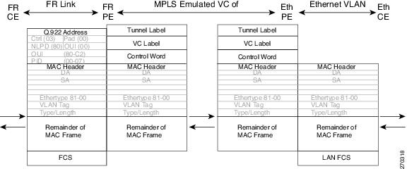


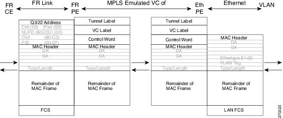

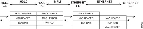

 Feedback