MPLS Traffic Engineering Path Link and Node Protection Configuration Guide, Cisco IOS XE 3S (Cisco ASR 900 Series)
Bias-Free Language
The documentation set for this product strives to use bias-free language. For the purposes of this documentation set, bias-free is defined as language that does not imply discrimination based on age, disability, gender, racial identity, ethnic identity, sexual orientation, socioeconomic status, and intersectionality. Exceptions may be present in the documentation due to language that is hardcoded in the user interfaces of the product software, language used based on RFP documentation, or language that is used by a referenced third-party product. Learn more about how Cisco is using Inclusive Language.
MPLS Traffic Engineering BFD-triggered Fast Reroute
The MPLS Traffic Engineering: BFD-triggered Fast Reroute feature allows you to obtain link and node protection by using the
Bidirectional Forwarding Detection (BFD) protocol to provide fast forwarding path failure detection times for all media types,
encapsulations, topologies, and routing protocols. In addition to fast forwarding path failure detection, BFD provides a consistent
failure detection method for network administrators.
Prerequisites for MPLS Traffic Engineering BFD-triggered Fast Reroute
Configure BFD. Refer to the
Bidirectional Forwarding Detection process module.
Enable MPLS TE on all relevant routers and interfaces.
Configure MPLS TE tunnels.
For additional prerequisites, refer to the MPLS TE: Link and Node Protection, with RSVP Hellos Support (with Fast Tunnel
Interface Down Detection) process module.
Restrictions for MPLS Traffic Engineering BFD-triggered Fast Reroute
You cannot configure BFD and RSVP Hellos on the same interface.
BFD may not be supported on some interfaces.
For additional restrictions, refer to the MPLS TE: Link and Node Protection, with RSVP Hellos Support (with Fast Tunnel Interface
Down Detection) process module.
Information About MPLS Traffic Engineering BFD-triggered Fast Reroute
Bidirectional Forwarding Detection
Bidirectional Forwarding Detection (BFD) is a detection protocol designed to provide fast forwarding path failure detection
times for all media types, encapsulations, topologies, and routing protocols. In addition to fast forwarding path failure
detection, BFD provides a consistent failure detection method for network administrators. Because the network administrator
can use BFD to detect forwarding path failures at a uniform rate, rather than the variable rates for different routing protocol
Hello mechanisms, network profiling and planning will be easier, and reconvergence time will be consistent and predictable.
Fast Reroute
Fast Reroute (FRR) is a mechanism for protecting Multiprotocol Label Switching (MPLS) traffic engineering (TE) label switched
paths (LSPs) from link and node failures by locally repairing the LSPs at the point of failure, allowing data to continue
to flow on them while their headend routers attempt to establish new end-to-end LSPs to replace them. FRR locally repairs
the protected LSPs by rerouting them over backup tunnels that bypass failed links or nodes.
Link Protection
Backup tunnels that bypass only a single link of the LSP’s path provide link protection. They protect LSPs if a link along
their path fails by rerouting the LSP’s traffic to the next hop (bypassing the failed link). These are referred to as next-hop
(NHOP) backup tunnels because they terminate at the LSP’s next hop beyond the point of failure.
Node Protection
FRR provides node protection for LSPs. Backup tunnels that bypass next-hop nodes along LSP paths are called next-next-hop
(NNHOP) backup tunnels because they terminate at the node following the next-hop node of the LSP paths, thereby bypassing
the next-hop node. They protect LSPs if a node along their path fails by enabling the node upstream of the failure to reroute
the LSPs and their traffic around the failed node to the next-next hop. FRR supports the use of RSVP Hellos to accelerate
the detection of node failures. NNHOP backup tunnels also provide protection from link failures, because they bypass the failed
link as well as the node.
Bandwidth Protection
NHOP and NNHOP backup
tunnels can be used to provide bandwidth protection for rerouted LSPs. This is
referred to as backup bandwidth. You can associate backup bandwidth with NHOP
or NNHOP backup tunnels. This informs the router of the amount of backup
bandwidth a particular backup tunnel can protect. When a router maps LSPs to
backup tunnels, bandwidth protection ensures that an LSP uses a given backup
tunnel only if there is sufficient backup bandwidth. The router selects which
LSPs use which backup tunnels to provide maximum bandwidth protection. That is,
the router determines the best way to map LSPs onto backup tunnels to maximize
the number of LSPs that can be protected.
.
LSPs that have the
“bandwidth protection desired” bit set have a higher right to select backup
tunnels that provide bandwidth protection; that is, those LSPs can preempt
other LSPs that do not have that bit set. For more information, see the
"Prioritizing Which LSPs Obtain Backup Tunnels with Bandwidth Protection"
section.
How to Configure MPLS Traffic Engineering BFD-triggered Fast Reroute
This section shows you how to add FRR protection to a network in which MPLS TE LSPs are configured.
The following sections describe how to use FRR to protect LSPs in your network from link or node failures. Each task is identified
as either required or optional.
Note
You can perform the configuration tasks in any order.
Note
An NNHOP backup tunnel must not
go via the NHOP backup tunnel.
Enabling BFD Support on the Router
SUMMARY STEPS
enable
configureterminal
iprsvpsignallinghellobfd
exit
DETAILED STEPS
Command or Action
Purpose
Step 1
enable
Example:
Router> enable
Enables privileged EXEC mode.
Enter your password if prompted.
Step 2
configureterminal
Example:
Router# configure terminal
Enters global configuration mode.
Step 3
iprsvpsignallinghellobfd
Example:
Router(config)# ip rsvp signalling hello bfd
Enables the BFD protocol on the router for MPLS TE link and node protection.
Step 4
exit
Example:
Router(config)# exit
Exits to privileged EXEC mode.
Enabling Fast Reroute on LSPs
LSPs can use backup tunnels only if the LSPs have been configured as fast reroutable. To enable FRR on the LSP, enter the
following commands at the headend of each LSP.
Enables an MPLS TE tunnel to use an established backup tunnel if there is a link or node failure.
Thebw-protect keyword sets the “bandwidth protection desired” bit so that backup bandwidth protection is enabled.
Thenode-protect keyword sets the “node protection desired” bit so that backup bandwidth protection is enabled.
Step 5
exit
Example:
Router(config-if)# exit
Exits interface configuration mode and returns to global configuration mode.
Step 6
exit
Example:
Router(config)# exit
Exits global configuration mode and returns to privileged EXEC mode.
Creating a Backup Tunnel to the Next Hop or to the Next-Next Hop
To create a backup tunnel to the next hop or to the next-next hop, perform the following task.
Enter the commands on the node that will be the headend of the backup tunnel (that is, the node whose downstream link or
node may fail). The node on which you enter the commands must be a supported platform. See the Finding Feature Information
section.
Creating a backup tunnel is basically no different from creating any other tunnel.
Note
When using the
exclude-address command to specify the path for a backup tunnel, you must exclude an interface address to avoid a link (for creating an NHOP
backup tunnel), or a router-ID address to avoid a node (for creating an NNHOP backup tunnel).
Creates a new tunnel interface and enters interface configuration mode.
The
number argument is the number of the tunnel.
Step 4
ipunnumberedtypenumber
Example:
Router(config-if)# ip unnumbered loopback 0
Enables IP processing on an interface without assigning an explicit IP address to the interface.
The
type and
number arguments name the type and number of another interface on which the router has an assigned IP address. It cannot be another
unnumbered interface.
Note
Theipunnumberedloopback0 command gives the tunnel interface an IP address that is the same as that of interface loopback 0. This command is not effective
until loopback 0 has been configured with an IP address.
Step 5
tunneldestinationip-address
Example:
Router(config-if)# tunnel destination 10.3.3.3
Specifies the destination for a tunnel interface.
Theip-addressargument specifies the IP address of the device, expressed in dotted decimal notation, where the tunnel will terminate. That
address should be the router ID of the device that is the NHOP or NNHOP of LSPs to be protected.
Router(config-if)# tunnel mpls traffic-eng path-option 10 explicit name avoid-protected-link
Configures the tunnel to use a named IP explicit path or a path dynamically calculated from the traffic engineering topology
database.
The
number argument is the preference for this path option. When you configure multiple path options, lower numbered options are preferred.
Valid values are from 1 to 1000.
The
dynamic keyword indicates that the path of the label switched path (LSP) is dynamically calculated.
The
explicit keyword indicates that the path of the LSP is an IP explicit path.
The
namepath-name keyword and argument are the path name of the IP explicit path that the tunnel uses with this option.
The
identifierpath-numberkeyword and argument pair names the path number of the IP explicit path that the tunnel uses with this option. The range is
from 1 to 65535.
The
lockdown keyword specifies that The LSP cannot be reoptimized.
Note
A dynamic path is used if an explicit path is currently unavailable.
Step 8
exit
Example:
Router(config-if)# exit
Exits interface configuration mode and enter global configuration mode.
Step 9
ipexplicit-pathnamename
Example:
Router(config)# ip explicit-path name avoid-protected-link
Enters IP explicit path mode for IP explicit paths to create the named path.
The
name argument is the name of the explicit path.
The
address argument specifies the IP address of the link to be protected for link protection. For node protection, it specifies the
router ID of the node to be protected.
Note
Backup tunnel paths can be dynamic or explicit and they do not have to use an excluded address. Because backup tunnels must
avoid the protected link or node, it is convenient to use an excluded address.
Step 11
exit
Example:
Router(cfg-ip-expl-path))# exit
Exits IP explicit path configuration mode and returns to global configuration mode.
Step 12
exit
Example:
Router(config)# exit
Exits global configuration mode and returns to privileged EXEC mode.
Assigning Backup Tunnels to a Protected Interface
To assign one or more backup tunnels to a protected interface, perform the following task.
Enter the commands on the node that will be the headend of the backup tunnel (that is, the node whose downstream link or
node may fail). The node on which you enter the commands must be a supported platform. See the Finding Feature Information
section.
Note
You must configure the interface to have an IP address and to enable the MPLS TE tunnel feature.
SUMMARY STEPS
enable
configureterminal
interfacetype slot/subslot/port[.subinterface]
mplstraffic-engbackup-pathtunneltunnel-id
exit
exit
DETAILED STEPS
Command or Action
Purpose
Step 1
enable
Example:
Router> enable
Enables privileged EXEC mode.
Enter your password if prompted.
Step 2
configureterminal
Example:
Router# configure terminal
Enters global configuration mode.
Step 3
interfacetype slot/subslot/port[.subinterface]
Example:
Router(config)# interface Gigabitethernet 2/1/0
Configures an interface type and enters interface configuration mode.
The
type argument is the type of interface to be configured.
The
slot argument is the chassis slot number. Refer to the appropriate hardware manual for slot information. For SIPs, refer to the
platform-specific SPA hardware installation guide or the corresponding “Identifying Slots and Subslots for SIPs and SPAs”
topic in the platform-specific SPA software configuration guide.
The/subslot keyword and argument pair is the secondary slot number on a SIP where a SPA is installed. The slash (/) is required.
Refer to the platform-specific SPA hardware installation guide and the corresponding “Specifying the Interface Address on
a SPA” topic in the platform-specific SPA software configuration guide for subslot information.
The/port keyword and argument pair is the port or interface number. The slash (/) is required.
Refer to the appropriate hardware manual for port information. For SPAs, refer to the corresponding “Specifying the Interface
Address on a SPA” topics in the platform-specific SPA software configuration guide
The
.subinterface-numberkeyword and argument pair is the subinterface number in the range 1 to 4294967293. The number that precedes the period (.)
must match the number to which this subinterface belongs.
Configures the physical interface to use for a backup tunnel in the event of a detected failure on that interface.
The
tunnel-idargument is a string that identifies a backup tunnel to use if there is a link or node failure for LSPs going out the configured
interface.
Note
You can enter this command multiple times to associate multiple backup tunnels with the same protected interface.
Step 5
exit
Example:
Router(config-if))# exit
Exits interface configuration mode and returns to global configuration mode.
Step 6
exit
Example:
Router(config)# exit
Exits global configuration mode and returns to privileged EXEC mode.
Configures an interface type and enters interface configuration mode.
The type argument is the type of interface to be configured.
The slot argument is the chassis slot number. Refer to the appropriate hardware manual for slot information. For SIPs, refer to the
platform-specific SPA hardware installation guide or the corresponding “Identifying Slots and Subslots for SIPs and SPAs”
topic in the platform-specific SPA software configuration guide.
The/subslot keyword and argument pair is the secondary slot number on a SIP where a SPA is installed. The slash (/) is required.
Refer to the platform-specific SPA hardware installation guide and the corresponding “Specifying the Interface Address on
a SPA” topic in the platform-specific SPA software configuration guide for subslot information.
The/port keyword and argument pair is the port or interface number. The slash (/) is required.
Refer to the appropriate hardware manual for port information. For SPAs, refer to the corresponding “Specifying the Interface
Address on a SPA” topics in the platform-specific SPA software configuration guide
The .subinterface-numberkeyword and argument pair is the subinterface number in the range 1 to 4294967293. The number that precedes the period (.)
must match the number to which this subinterface belongs.
Step 4
iprsvpsignallinghellobfd
Example:
Router(config-if)# ip rsvp signalling hello bfd
Enables the BFD protocol on an interface for MPLS TE link and node protection.
The intervalmilliseconds keyword and argument pair specifies the rate at which BFD control packets will be sent to BFD peers. The configurable time
period for the milliseconds argument is from 50 to 999.
The min_rxmillisecond keyword and argument pair specifies the rate at which BFD control packets will be expected to be received from BFD peers.
The configurable time period for the milliseconds argument is from 1 to 999.
The multiplier interval-multiplierkeyword and argument pair specifies the number of consecutive BFD control packets that must be missed from a BFD peer before
BFD declares that the peer is unavailable and the Layer 3 BFD peer is informed of the failure. The configurable value range
for the multiplier-value argument is from 3 to 50.
Step 6
exit
Example:
Router(config-if))# exit
Exits interface configuration mode and returns to global configuration mode.
Step 7
exit
Example:
Router(config)# exit
Exits global configuration mode and returns to privileged EXEC mode.
Associating Backup Bandwidth and Pool Type with a Backup Tunnel
To associate backup bandwidth with a backup tunnel and designate the type of LSP that can use a backup tunnel, enter the following
tasks.
Changes the backup protection preemption algorithm from minimize the number of LSPs that are demoted to minimize the amount
of bandwidth that is wasted.
Step 7
exit
Example:
Router(config-if)# exit
Exits to privileged EXEC mode.
Verifying That Fast Reroute Is Operational
SUMMARY STEPS
showmplstraffic-engtunnelsbrief
showiprsvpsenderdetail
showmplstraffic-engfast-reroutedatabase
showmplstraffic-engtunnelsbackup
showmplstraffic-engfast-reroutedatabase
showiprsvpreservationdetail
showiprsvphello
showiprsvpinterfacedetail
showiprsvphellobfdnbr
showiprsvphellobfdnbrdetail
showiprsvphellobfdnbrsummary
DETAILED STEPS
Step 1
showmplstraffic-engtunnelsbrief
Use this command to verify that backup tunnels are up:
Example:
Router# show mpls traffic-eng tunnels brief

Signalling Summary:
    LSP Tunnels Process:           running
    RSVP Process:                  running
    Forwarding:                    enabled
    Periodic reoptimization:       every 3600 seconds, next in 1706 seconds
TUNNEL NAME                      DESTINATION      UP IF     DOWN IF   STATE/PROT
Router_t1                        10.112.0.12      -         Gi4/0/1   up/up
Router_t2                        10.112.0.12      -         unknown   up/down
Router_t3                        10.112.0.12      -         unknown   admin-down
Router_t1000                     10.110.0.10      -         unknown   up/down
Router_t2000                     10.110.0.10      -         Gi4/0/1   up/up
Displayed 5 (of 5) heads, 0 (of 0) midpoints, 0 (of 0) tails
Step 2
showiprsvpsenderdetail
Use this command to verify that LSPs are protected by the appropriate backup tunnels.
Following is sample output from the
showiprsvpsenderdetail command when the command is entered at the router acting as the point of local repair (PLR) before a failure:
Example:
Router# show ip rsvp sender detail

PATH:
 Tun Dest:   10.10.0.6  Tun ID: 100  Ext Tun ID: 10.10.0.1
 Tun Sender: 10.10.0.1  LSP ID: 31
 Path refreshes:
  arriving: from PHOP 10.10.7.1 on Et0/0 every 30000 msecs
 Session Attr:
  Setup Prio: 7, Holding Prio: 7
  Flags: (0x7) Local Prot desired, Label Recording, SE Style
  session Name: R1_t100
 ERO: (incoming)
  10.10.7.2 (Strict IPv4 Prefix, 8 bytes, /32)
  10.10.0.6 (Strict IPv4 Prefix, 8 bytes, /32)
 RRO:
   10.10.7.1/32, Flags:0x0 (No Local Protection)
   10.10.4.1/32, Flags:0x9 (Local Prot Avail/to NNHOP) !Available to NNHOP
   10.10.1.1/32, Flags:0x0 (No Local Protection)
 Traffic params - Rate: 10K bits/sec, Max. burst: 1K bytes
   Min Policed Unit: 0 bytes, Max Pkt Size 4294967295 bytes
 Fast-Reroute Backup info:
   Inbound  FRR: Not active
   Outbound FRR: No backup tunnel selected
 Path ID handle: 50000416.
 Incoming policy: Accepted. Policy source(s): MPLS/TE
 Status: Proxy-terminated
Step 3
showmplstraffic-engfast-reroutedatabase
Enter the
cleariprsvphelloinstancecounterscommand to verify the following:
MPLS TE FRR Node Protection has been enabled.
A certain type of LSP can use a backup tunnel.
The following command output displays the LSPs that are protected:
Example:
Router# show mpls traffic-eng fast-reroute database
Tunnel head end item frr information:
Protected tunnel              In-label Out intf/label   FRR intf/label   Status
Tunnel500                     Tun hd   AT4/0.100:Untagg Tu501:20         ready
Prefix item frr information:
Prefix             Tunnel     In-label Out intf/label    FRR intf/label  Status
10.0.0.8/32        Tu500      18       AT4/0.100:Pop ta  Tu501:20        ready
10.0.8.8/32        Tu500      19       AT4/0.100:Untagg  Tu501:20        ready
10.8.9.0/24        Tu500      22       AT4/0.100:Untagg  Tu501:20        ready
LSP midpoint item frr information:
LSP identifier     In-label Out     intf/label     FRR intf/label     Status
If Label Distribution Protocol (LDP) is not enabled, separate prefix items are not shown because all prefixes then use a
single rewrite. To confirm that a particular IP prefix is FRR protected, even though it is not shown in this display, enter
it within the
showmplsforwarding-tableip-addressdetail command. The final line of the display will tell whether that prefix is protected:
Example:
Router# show mpls forwarding-table 10.0.0.11 32 detail

Local    Outgoing    Prefix         Bytes tag   Outgoing               Next Hop
tag      tag or VC   or Tunnel Id   switched    interface
Tun hd   Untagged    10.0.0.11/32   48 5/0      Gi5/0    point2point
          MAC/Encaps=4/8, MTU=1520, Tag Stack{22}
          48D18847 00016000
          No output feature configured
          Fast Reroute Protection via (Tu0, outgoing label 12304)
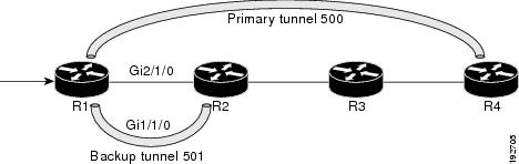
The following command output displays the LSPs that are protected when the FRR primary tunnel is over a Gigabit Ethernet
interface and the backup tunnel is over a Gigabit Ethernet interface. As shown in the figure below, interface Gigabit Ethernet
2/1/0 is protected by backup tunnel 501.
Figure 1. Protected LSPs
The figure above shows the following:
Primary tunnel 500--Path is R1 via Gigabit Ethernet2/1/0 to R2 to R3 to R4.
FRR backup tunnel 501--Path is R1 via Gigabit Ethernet1/1/0 to R2.
Interface Gigabit Ethernet1/1/0--Protected by backup tunnel 501.
Example:
Router# show mpls traffic-eng fast-reroute database
Tunnel head end item frr information:
Protected tunnel In-label Out intf/label FRR intf/label Status
Tunnel500 Tun hd AT4/0.100:Untagg Tu501:20 ready
Prefix item frr information:
Prefix Tunnel In-label Out intf/label FRR intf/label Status
10.0.0.8/32 Tu500 18 AT4/0.100:Pop ta Tu501:20 ready
10.0.8.8/32 Tu500 19 AT4/0.100:Untagg Tu501:20 ready
10.8.9.0/24 Tu500 22 AT4/0.100:Untagg Tu501:20 ready
LSP midpoint item frr information:
LSP identifier In-label Out intf/label FRR intf/label Status
The following command output displays the LSPs that are protected when the FRR backup tunnel is over a Gigabit Ethernet interface.
Example:
Router# show mpls traffic-eng fast-reroute database

Tunnel head end item frr information:
Protected tunnel In-label Out intf/label FRR intf/label Status
Tunnel500 Tun hd PO2/0:Untagged Tu501:20 ready
Prefix item frr information:
Prefix Tunnel In-label Out intf/label FRR intf/label Status
10.0.0.8/32 Tu500 18 PO2/0:Pop tag Tu501:20 ready
10.0.8.8/32 Tu500 19 PO2/0:Untagged Tu501:20 ready
10.8.9.0/24 Tu500 22 PO2/0:Untagged Tu501:20 ready
LSP midpoint item frr information:
LSP identifier In-label Out intf/label FRR intf/label Status
Step 4
showmplstraffic-engtunnelsbackup
For backup tunnels to be operational, the LSP must be reroutable. At the headend of the LSP, enter the
showruninterfacetunneltunnel-number command. The output should include the
tunnelmplstraffic-engfast-reroute command. If it does not, enter this command for the tunnel.
On the router where the backup tunnels originate, enter the
showmplstraffic-engtunnelsbackupcommand. Following is sample command output:
Example:
Router# show mpls traffic-eng tunnels backup
Router_t578
  LSP Head, Tunnel578, Admin: up, Oper: up
  Src 10.55.55.55, Dest 10.88.88.88, Instance 1
  Fast Reroute Backup Provided:
    Protected i/fs: PO1/0, PO1/1, PO3/3
    Protected lsps: 1
    Backup BW: any pool unlimited; inuse: 100 kbps
Router_t5710
  LSP Head, Tunnel5710, Admin: admin-down, Oper: down
  Src 10.55.55.55, Dest 10.7.7.7, Instance 0
  Fast Reroute Backup Provided:
    Protected i/fs: PO1/1
    Protected lsps: 0
    Backup BW: any pool unlimited; inuse: 0 kbps
Router_t5711
  LSP Head, Tunnel5711, Admin: up, Oper: up
  Src 10.55.55.55, Dest 10.7.7.7, Instance 1
  Fast Reroute Backup Provided:
    Protected i/fs: PO1/0
    Protected lsps: 2
    Backup BW: any pool unlimited; inuse: 6010 kbps
The command output will allow you to verify the following:
Backup tunnel exists--Verify that there is a backup tunnel that terminates at this LSP’s NHOP or NNHOP. Look for the LSP’s
NHOP or NNHOP in the Dest field.
Backup tunnel is up--To verify that the backup tunnel is up, look for “Up” in the Oper field.
Backup tunnel is associated with the LSP’s interface--Verify that the interface for the LSP is allowed to use this backup
tunnel. Look for the LSP’s output interface in the protected i/fs field list.
Backup tunnel has sufficient bandwidth--If you restricted the amount of bandwidth a backup tunnel can hold, verify that the
backup tunnel has sufficient bandwidth to hold the LSPs that would use this backup tunnel if there is a failure. The bandwidth
of an LSP is defined by the line
tunnelmplstraffic-engbandwidth at the headend of the LSP. To determine the available bandwidth on a backup tunnel, look at the “cfg” and “inuse” fields.
If there is insufficient backup bandwidth to accommodate the LSPs that would use this backup tunnel in the event of a failure,
create an additional backup tunnel or increase the backup bandwidth of the existing tunnel by using the
tunnelmplstraffic-engbandwidth command.
Note
In order to determine how much bandwidth is sufficient, offline capacity planning may be required.
Backup tunnel has appropriate bandwidth type--If you restricted the type of LSPs (subpool or global pool) that can use this
backup tunnel, verify that the LSP is the appropriate type for the backup tunnel. The type of the LSP is defined by the line
tunnelmplstraffic-engbandwidth at the headend of this LSP. If this line contains the word “sub pool”, then it uses subpool bandwidth; otherwise, it uses
global pool bandwidth. Verify that the type matches the type the backup tunnel can hold by looking in the output of the
tunnelmplstraffic-engbandwidthcommand.
If none of the verification actions described succeed, enable debug by entering the
debugiprsvpfast-reroute command and the
debugmplstraffic-engfast-reroute command on the router that is the headend of the backup tunnel. Then do the following:
Enter the
shutdown command for the primary tunnel.
Enter the
noshutdown command for the primary tunnel.
View the debug output.
Step 5
showmplstraffic-engfast-reroutedatabase
Enter the
cleariprsvphelloinstancecounters command to verify the following:
MPLS TE FRR node protection has been enabled.
A certain type of LSP can use a backup tunnel.
The following command output displays the LSPs that are protected:
Example:
Router# show mpls traffic-eng fast-reroute database
Tunnel head end item frr information:
Protected Tunnel   In-label   intf/label       FRR intf/label      Status
Tunne1l0           Tun        Gi0/1/0:Untagged   Tu0:12304           ready
Prefix item frr information:
Prefix        Tunnel  In-label    Out intf/label  FRR intf/label   Status
10.0.0.11/32  Tu110   Tun hd      Gi0/1/0:Untagged  Tu0:12304        ready
LSP midpoint frr information:
LSP identifier       In-label   Out intf/label   FRR intf/label    Status
10.0.0.12 1 [459]    16         Gi0/1/1:17         Tu2000:19         ready
Note
If Label Distribution Protocol (LDP) is not enabled, separate prefix items are not shown because all prefixes then use a
single rewrite. To confirm that a particular IP prefix is FRR protected, even though it is not shown in this display, enter
it within the
showmplsforwarding-tableip-addressdetail command. The final line of the display will tell whether that prefix is protected.
Example:
Router# show mpls forwarding-table 10.0.0.11 32 detail

Local    Outgoing    Prefix         Bytes tag    Outgoing       Next Hop
tag      tag or VC   or Tunnel Id   switched     interface
Tun hd   Untagged    10.0.0.11/32   48 Gi0/1/0     point2point
          MAC/Encaps=4/8, MTU=1520, Tag Stack{22}
          48D18847 00016000
          No output feature configured
          Fast Reroute Protection via (Tu0, outgoing label 12304)
Step 6
showiprsvpreservationdetail
Following is sample output from the
showiprsvpreservationdetail command entered at the headend of a primary LSP. Entering the command at the headend of the primary LSP shows, among other
things, the status of FRR (that is, local protection) at each hop this LSP traverses. The per-hop information is collected
in the Record Route Object (RRO) that travels with the Resv message from the tail to the head.
Example:
Router# show ip rsvp reservation detail
Reservation:
  Tun Dest:   10.1.1.1  Tun ID: 1  Ext Tun ID: 10.1.1.1
  Tun Sender: 10.1.1.1  LSP ID: 104
  Next Hop: 10.1.1.2 on Gi1/0/2
  Label: 18 (outgoing)
  Reservation Style is Shared-Explicit, QoS Service is Controlled-Load
  Average Bitrate is 0 bits/sec, Maximum Burst is 1K bytes
  Min Policed Unit: 0 bytes, Max Pkt Size: 0 bytes
  RRO:
    10.1.1.1/32, Flags:0x1 (Local Prot Avail/to NHOP)
      Label subobject: Flags 0x1, C-Type 1, Label 18
    10.1.1.1/32, Flags:0x0 (Local Prot Avail/In Use/Has BW/to NHOP)
      Label subobject: Flags 0x1, C-Type 1, Label 16
    10.1.1.2/32, Flags:0x0 (No Local Protection)
      Label subobject: Flags 0x1, C-Type 1, Label 0
  Resv ID handle: CD000404.
  Policy: Accepted. Policy source(s): MPLS/TE
Notice the following about the primary LSP:
It has protection that uses an NHOP backup tunnel at its first hop.
It has protection and is actively using an NHOP backup tunnel at its second hop.
It has no local protection at its third hop.
The RRO display shows the following information for each hop:
Whether local protection is available (that is, whether the LSP has selected a backup tunnel)
Whether local protection is in use (that is, whether the LSP is using its selected backup tunnel)
Whether the selected backup tunnel is an NHOP or NNHOP backup tunnel
Whether the backup tunnel used at this hop provides bandwidth protection
Step 7
showiprsvphello
Use this command to display hello status and statistics for FRR, reroute (hello state timer), and graceful restart. Following
is sample output:
Example:
Router# show ip rsvp hello

Hello:
 RSVP Hello for Fast-Reroute/Reroute: Enabled
  Statistics: Disabled
 BFD for Fast-Reroute/Reroute: Enabled
 RSVP Hello for Graceful Restart: Disabled
Step 8
showiprsvpinterfacedetail
Use this command to display the interface configuration for Hello. Following is sample output:
Example:
Router# show ip rsvp interface detail

Gi2/1/1:
 RSVP: Enabled
 Interface State: Up
 Bandwidth:
  Curr allocated: 0 bits/sec
  Max. allowed (total): 0 bits/sec
  Max. allowed (per flow): 0 bits/sec
  Max. allowed for LSP tunnels using sub-pools (pool 1): 0 bits/sec
  Set aside by policy (total): 0 bits/sec
 Signalling:
  DSCP value used in RSVP msgs: 0x3F
  Number of refresh intervals to enforce blockade state: 4
 Authentication: disabled
  Key chain: <none>
  Type:  md5
  Window size: 1
  Challenge:  disabled
 FRR Extension:
  Backup Path: Configured (or "Not Configured")
 BFD Extension:
  State: Disabled
  Interval: Not Configured
 RSVP Hello Extension:
  State: Disabled
  Refresh Interval: FRR: 200  , Reroute: 2000
  Missed Acks:      FRR: 4    , Reroute: 4
  DSCP in HELLOs:   FRR: 0x30 , Reroute: 0x30
Step 9
showiprsvphellobfdnbr
Use this command to display information about all MPLS traffic engineering link and node protected neighbors that use the
BFD protocol. Following is sample output. The command output is the same as the
showiprsvphellobfdnbrsummary command output.
Example:
Router# show ip rsvp hello bfd nbr

Client  Neighbor    I/F     State   LostCnt   LSPs
FRR     10.0.0.6    Gi2/1/1  Up      0         1
Step 10
showiprsvphellobfdnbrdetail
Use this command to display detailed information about all MPLS traffic engineering link and node protected neighbors that
use the BFD protocol:
Example:
Router# show ip rsvp hello bfd nbr detail

 Hello Client Neighbors
 Remote addr 10.0.0.6, Local addr  10.0.0.7
  Type: Active
  I/F: Gi2/1/1
  State: Up (for 00:09:41)
  Clients: FRR
  LSPs protecting: 1 (frr: 1, hst upstream: 0 hst downstream: 0)
  Communication with neighbor lost: 0
Step 11
showiprsvphellobfdnbrsummary
Use this command to display summarized information about all MPLS traffic engineering link and node protected neighbors that
use the BFD protocol. The command output is the same as the
showiprsvphellobfdnbrsummary command output.
Example:
Router# show ip rsvp hello bfd nbr summary

Client  Neighbor    I/F     State  LostCnt  LSPs
FRR     10.0.0.6   Gi2/1/1  Up     0        1
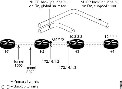
Configuration Examples for MPLS Traffic Engineering BFD-triggered Fast Reroute
The examples in this section are based on the backup tunnels shown in the figure below.
Figure 2. Backup Tunnels
Example Enabling BFD Support on the Router
The following example enables the BFD protocol on the router:
Router(config)# ip rsvp signalling hello bfd
Example Enabling Fast Reroute on LSPs
On router R1 in the figure above, enter interface configuration mode for each tunnel to be protected (Tunnel 1000 and Tunnel
2000). Enable these tunnels to use a backup tunnel in case of a link or node failure along their paths.
Tunnel 1000 will use ten units of bandwidth from the subpool.
Tunnel 2000 will use five units of bandwidth from the global pool. The “bandwidth protection desired” bit and the “node protection
desired bit” have been set by specifying
bw-prot and
node-prot, respectively, in the
tunnelmplstraffic-engfast-reroute command.
Example Associating Backup Bandwidth and Pool Type with Backup Tunnels
In the figure above, backup tunnel 1 is to be used only by LSPs that take their bandwidth from the global pool. It does not
provide bandwidth protection. Backup tunnel 2 is to be used only by LSPs that take their bandwidth from the subpool. Backup
tunnel 2 provides bandwidth protection for up to 1000 units.
This global configuration is required only to change the backup protection preemption algorithm from minimize the number of
LSPs that are demoted to minimize the amount of bandwidth that is wasted.
No new or modified RFCs are supported by this feature, and support for existing RFCs has not been modified by this feature.
--
Technical Assistance
Description
Link
The Cisco Support and Documentation website provides online resources to download documentation, software, and tools. Use
these resources to install and configure the software and to troubleshoot and resolve technical issues with Cisco products
and technologies. Access to most tools on the Cisco Support and Documentation website requires a Cisco.com user ID and password.
Feature Information for MPLS Traffic Engineering BFD-triggered Fast Reroute
The following table provides release information about the feature or features described in this module. This table lists
only the software release that introduced support for a given feature in a given software release train. Unless noted otherwise,
subsequent releases of that software release train also support that feature.
Use Cisco Feature Navigator to find information about platform support and Cisco software image support. To access Cisco
Feature Navigator, go to www.cisco.com/go/cfn. An account on Cisco.com is not required.
Table 1. Feature Information for MPLS Traffic Engineering: BFD-triggered Fast Reroute
Feature Name
Releases
Feature Information
MPLS Traffic Engineering: BFD-triggered Fast Reroute
12.2(33)SRC
15.3(1)S
15.1(1)SY
The MPLS Traffic Engineering: BFD-triggered Fast Reroute feature allows you to obtain link and node protection by using the
Bidirectional Forwarding Detection (BFD) protocol to provide fast forwarding path failure detection times for all media types,
encapsulations, topologies, and routing protocols. In addition to fast forwarding path failure detection, BFD provides a consistent
failure detection method for network administrators.
The following commands were introduced or modified by this feature:
cleariprsvphellobfd,
iprsvpsignallinghellobfd (configuration),
iprsvpsignallinghellobfd (interface),
showiprsvphello,
showiprsvphellobfdnbr,
showiprsvphellobfdnbrdetail,
showiprsvphellobfdnbrsummary, and
showiprsvpinterfacedetail.

 Feedback