-
- IP Access List Features Roadmap
- IP Access List Overview
- Creating an IP Access List and Applying It to an Interface
- Creating an IP Access List to Filter IP Options TCP Flags Noncontiguous Ports or TTL Values
- Refining an IP Access List
- Displaying and Clearing IP Access List Data Using ACL Manageability
- Controlling Access to a Virtual Terminal Line
- Access List-Based RBSCP
- ACL IP Options Selective Drop
- ACL Authentication of Incoming rsh and rcp Requests
- Configuring Lock-and-Key Security for Dynamic Access Lists
- Configuring IP Session Filtering of Reflexive Access Lists
- Configuring TCP Intercept and Preventing Denial-of-Service Attacks
-
- Configuring Context-based Access Control
- Application Firewall - Instant Message Traffic Enforcement
- Cisco IOS Firewall MIB
- Cisco IOS Firewall Performance Improvements
- Cisco IOS Firewall Stateful Failover
- Cisco IOS Firewall Support for TRP
- Email Inspection Engine
- ESMTP Support for Cisco IOS Firewall
- Firewall ACL Bypass
- Firewall N2H2 Support
- Firewall Stateful Inspection of ICMP
- Firewall Support for SIP
- Firewall Support of Skinny Client Control Protocol
- Firewall Websense URL Filtering
- Granular Protocol Inspection
- HTTP Inspection Engine
- Inspection of Router-Generated Traffic
- TCP Out-of-Order Packet Support for Cisco IOS Firewall and Cisco IOS IPS
- Transparent Cisco IOS Firewall
- Virtual Fragmentation Reassembly
- VRF Aware Cisco IOS Firewall
- Configuring Port to Application Mapping
- Configuring Cisco IOS Intrusion Prevention System (IPS)
- Configuring IP Security Options
Cisco IOS Security Configuration Guide: Securing the Data Plane, Release 12.4
Bias-Free Language
The documentation set for this product strives to use bias-free language. For the purposes of this documentation set, bias-free is defined as language that does not imply discrimination based on age, disability, gender, racial identity, ethnic identity, sexual orientation, socioeconomic status, and intersectionality. Exceptions may be present in the documentation due to language that is hardcoded in the user interfaces of the product software, language used based on RFP documentation, or language that is used by a referenced third-party product. Learn more about how Cisco is using Inclusive Language.
- Updated:
- March 26, 2008
Chapter: Transparent Cisco IOS Firewall
- Finding Feature Information
- Contents
- Restrictions for Transparent Cisco IOS Firewall
- Information About Transparent Cisco IOS Firewall
- How to Configure a Transparent Cisco IOS Firewall
Transparent Cisco IOS Firewall
The Transparent Cisco IOS Firewall feature allows users to "drop" a Cisco IOS Firewall in front of their existing network without changing the statically defined IP addresses of their network-connected devices. Thus, users can allow selected devices from a subnet to traverse the firewall while access to other devices on the same subnet is denied.
Finding Feature Information
Your software release may not support all the features documented in this module. For the latest feature information and caveats, see the release notes for your platform and software release. To find information about the features documented in this module, and to see a list of the releases in which each feature is supported, see the "Feature Information for Transparent Cisco IOS Firewall" section.
Use Cisco Feature Navigator to find information about platform support and Cisco software image support. To access Cisco Feature Navigator, go to http://www.cisco.com/go/cfn. An account on Cisco.com is not required.
Contents
•![]() Restrictions for Transparent Cisco IOS Firewall
Restrictions for Transparent Cisco IOS Firewall
•![]() Information About Transparent Cisco IOS Firewall
Information About Transparent Cisco IOS Firewall
•![]() How to Configure a Transparent Cisco IOS Firewall
How to Configure a Transparent Cisco IOS Firewall
•![]() Configuration Examples for Transparent Cisco IOS Firewall
Configuration Examples for Transparent Cisco IOS Firewall
•![]() Feature Information for Transparent Cisco IOS Firewall
Feature Information for Transparent Cisco IOS Firewall
Restrictions for Transparent Cisco IOS Firewall
Layer 3 IP Packet Support Only
Only IP packets (TCP, User Datagram Protocol [UDP] , and Internet Control Message Protocol [ICMP]) are subjected to inspection by the transparent firewall. Non-IP traffic is bridged as usual without interference from the transparent firewall. However, if users wish to block non-IP traffic, the MAC access control lists (ACLs) can be applied on interfaces to filter out non-IP traffic and allow only IP traffic.
The following example shows how to configure an ACL that permits all IP packets (0x0800) into the Ethernet interface but denies all Internetwork Packet Exchange (IPX) packets (0x8137):
Router(config)# access-list 201 permit 0x0800
Router(config)# access-list 201 deny 0x8137
Router(config)# interface ethernet 0
Router(config-if)# bridge-group 1 input-type-list 201
VLAN Trunk Bridging
Bridging between VLAN trunks works only for dot1q encapsulation; Inter-Switch Link (ISL) encapsulation will not work. (However, ISL VLANs will work if subinterfaces are created and placed in a bridge group.)
Information About Transparent Cisco IOS Firewall
•![]() Benefit of the Transparent Firewall
Benefit of the Transparent Firewall
•![]() Transparent Firewall Overview
Transparent Firewall Overview
•![]() Transparent Bridging Overview
Transparent Bridging Overview
•![]() Layer 2 and Layer 3 Firewalls Configured on the Same Router
Layer 2 and Layer 3 Firewalls Configured on the Same Router
Benefit of the Transparent Firewall
Added Security with Minimum Configuration
Users can simply drop a transparent Cisco IOS Firewall into an existing network without having to reconfigure their statically defined devices. Thus, the tedious and costly overhead that is required to renumber devices on the trusted network is eliminated.
Transparent Firewall Overview
A typical Cisco IOS Firewall is a Layer 3 device with trusted and untrusted interfaces on different IP subnets. A Layer 3 firewall works well with Cisco IOS devices that function as routers with preexisting subnet separations. However, when a Layer 3 firewall is placed in an existing network, the network IP addresses must be reconfigured to accommodate the firewall.
A transparent Cisco IOS firewall acts as a Layer 2 transparent bridge with context-based access control (CBAC) and ACLs configured on the bridged interface. Because the Layer 2 firewall intercepts packets at Layer 2 and is "transparent" to the existing network, Layer 3 firewall limitations are not applicable.
Transparent Bridging Overview
If configured for bridging, a Cisco IOS device can bridge any number of interfaces. The device can complete basic bridging tasks such as learning MAC addresses on ports to restrict collision domains and running Spanning Tree Protocol (STP) to prevent looping in the topology.
Within bridging, a user can configure Integrated Routed Bridging (IRB), which allows a device to bridge on some interfaces while a Layer 3 Bridged Virtual Interface (BVI) is presented for routing. The bridge can determine whether the packet is to be bridged or routed on the basis of the destination of the Layer 2 or Layer 3 IP address in the packet. Configured with an IP address, the BVI can manage the device even if there is no interface configured for routing.
Layer 2 and Layer 3 Firewalls Configured on the Same Router
A transparent firewall supports a BVI for routing, so a packet that comes in on a bridged interface can be bridged or routed out of the BVI. This functionality allows a Layer 2 (transparent) firewall and a Layer 3 firewall to be configured on the same router: The transparent firewall operates on the bridged packets while the "normal" firewall operates on the routed packets. For example, if you have six interfaces on your router and two of them are in a bridge group, you can simultaneously configure and run normal inspection on the remaining four interfaces.
How to Configure a Transparent Cisco IOS Firewall
You configure a transparent firewall just as you would configure a Layer 3 firewall (via the ip inspect command, which can be configured on any of the bridged interfaces for the transparent firewall). Also, you configure transparent bridging for a firewall just as you would for any other Cisco IOS device.
•![]() Configuring a Bridge Group (required)
Configuring a Bridge Group (required)
•![]() Configuring Inspection and ACLs (required)
Configuring Inspection and ACLs (required)
•![]() Forwarding DHCP Traffic (optional)
Forwarding DHCP Traffic (optional)
•![]() Monitoring Transparent Firewall Events (optional)
Monitoring Transparent Firewall Events (optional)
Configuring a Bridge Group
Perform this task to configure a bridge group and to associate interfaces or subinterfaces in the configured bridge group.
Prerequisites for BVI Configuration
•![]() If a BVI is not configured, you must disable IP routing (via the no ip routing command) for the bridging operation to take effect.
If a BVI is not configured, you must disable IP routing (via the no ip routing command) for the bridging operation to take effect.
•![]() If configured, a BVI must be configured with an IP address in the same subnet.
If configured, a BVI must be configured with an IP address in the same subnet.
•![]() You must configure a BVI if more than two interfaces are placed in a bridge group.
You must configure a BVI if more than two interfaces are placed in a bridge group.
Restrictions
•![]() If more than two interfaces are assigned to a bridge group, any routers that are acting as first-hop gateways to hosts that are in the bridged network (the bridge group) must allow ICMP time-to-live (TTL) exceeded messages to pass.
If more than two interfaces are assigned to a bridge group, any routers that are acting as first-hop gateways to hosts that are in the bridged network (the bridge group) must allow ICMP time-to-live (TTL) exceeded messages to pass.
•![]() Spanning Tree Bridge Protocol Data Units (BPDU) and packets that are to be routed out of the bridge, if IRB is configured, are not inspected.
Spanning Tree Bridge Protocol Data Units (BPDU) and packets that are to be routed out of the bridge, if IRB is configured, are not inspected.
SUMMARY STEPS
1. ![]() enable
enable
2. ![]() configure terminal
configure terminal
3. ![]() bridge bridge-group protocol {dec | ibm | ieee | vlan-bridge}
bridge bridge-group protocol {dec | ibm | ieee | vlan-bridge}
4. ![]() interface type number
interface type number
5. ![]() bridge-group bridge-group
bridge-group bridge-group
6. ![]() exit
exit
7. ![]() bridge irb
bridge irb
8. ![]() bridge bridge-group route protocol
bridge bridge-group route protocol
9. ![]() interface type number
interface type number
10. ![]() ip address ip-address mask
ip address ip-address mask
11. ![]() no shutdown
no shutdown
DETAILED STEPS
Examples
The following example shows how to configure interfaces "ethernet0" and "ethernet1" in a bridge group. These interfaces are associated with the BVI interface "BVI1," which can be reached from any host on either of the interfaces via the IP address 10.1.1.1.
Router(config)# bridge 1 protocol ieee
Router(config)# interface ethernet0
Router(config-if)# bridge-group 1
Router(config-if)# interface ethernet1
Router(config-if)# bridge-group 1
Router(config-if)# exit
! Configure the BVI.
Router(config)# bridge irb
Router(config)# bridge 1 route ip
Router(config)# interface BVI1
Router(config-if)# ip address 10.1.1.1 255.255.255.0
Router(config-if)# no shutdown
Troubleshooting Tips
To display the status of each bridge group, use the show bridge-group command or to display entries in the bridge table, use the show bridge command.
What to Do Next
After you have configured the bridge group, you must configure an inspection rule and at least one IP ACL. To complete this task, refer to the following section, "Configuring Inspection and ACLs."

Note ![]() If inspection is not configured on any interface in the bridge group, IP ACLs on bridged interfaces will not be active.
If inspection is not configured on any interface in the bridge group, IP ACLs on bridged interfaces will not be active.
Configuring Inspection and ACLs
Use this task to configure an inspection rule and apply it on the appropriate interface. Also, use this task to configure at least one ACL and apply it on one or more of the interfaces that you configured in the bridge group.
SUMMARY STEPS
1. ![]() enable
enable
2. ![]() configure terminal
configure terminal
3. ![]() ip inspect name protocol [alert {on | off}] [audit-trail {on | off}] [timeout seconds]
ip inspect name protocol [alert {on | off}] [audit-trail {on | off}] [timeout seconds]
4. ![]() interface type number
interface type number
5. ![]() ip inspect inspection-name {in | out}
ip inspect inspection-name {in | out}
6. ![]() exit
exit
7. ![]() access-list access-list-number {permit | deny} {type-code wild-mask | address mask}
access-list access-list-number {permit | deny} {type-code wild-mask | address mask}
8. ![]() interface type number
interface type number
9. ![]() ip access-group {access-list-number | access-list-name} {in | out}
ip access-group {access-list-number | access-list-name} {in | out}
DETAILED STEPS
Examples
The following example shows how to configure an inspection rule on interface "ethernet0," which is the inside interface. Policies can be specified via ACL 156 or 101; for example, ACL 156 can be used to specify that rlogin and rsh are not allowed for the internal users, and ACL 101 can be used to specify that an external host requires connectivity to a particular host in the internal domain.
Router(config)# ip inspect name test tcp
Router(config)# interface ethernet0
Router(config-if)# ip inspect test in
Router(config-if)# exit
!
! Configure the ACLs.
Router(config)# access-list 101 deny ip any any
Router(config)# access-list 156 permit 10.1.1.0 0.0.0.255 any
Router(config)# access-list 156 deny ip any any
Router(config)# interface ethernet0
Router(config-if) ip access-group 156 in
Router(config)# interface ethernet1
Router(config-if) ip access-group 101 in
Forwarding DHCP Traffic
Use this task to enable a transparent firewall to forward DHCP packets across the bridge without inspection; that is, the ip inspect L2-transparent dhcp-passthrough command overrides the ACL for DHCP packets, so DHCP packets will be forwarded even if the ACL is configured to deny all IP packets. Thus, clients on one side of the bridge can get an IP address from a DHCP server on the opposite side of the bridge.
SUMMARY STEPS
1. ![]() enable
enable
2. ![]() configure terminal
configure terminal
3. ![]() ip inspect L2-transparent dhcp-passthrough
ip inspect L2-transparent dhcp-passthrough
DETAILED STEPS
Monitoring Transparent Firewall Events
Use either of these optional steps to monitor the activity of the transparent firewall.
Note ![]() Effective with Cisco IOS Release 12.4(20)T, the debug ip inspect command is replaced by the debug policy-firewall command. See the Cisco IOS Debug Command Reference for more information.
Effective with Cisco IOS Release 12.4(20)T, the debug ip inspect command is replaced by the debug policy-firewall command. See the Cisco IOS Debug Command Reference for more information.
SUMMARY STEPS
1. ![]() enable
enable
2. ![]() debug ip inspect L2-transparent {packet | dhcp-passthrough}
debug ip inspect L2-transparent {packet | dhcp-passthrough}
3. ![]() show ip inspect {name inspection-name | config | interfaces | session [detail] | all}
show ip inspect {name inspection-name | config | interfaces | session [detail] | all}
DETAILED STEPS
Examples
The following sample output is a portion of the show ip inspect all command that shows the bridging interface:
Router# show ip inspect all
.
.
.
Interface Configuration
! Below is the bridging interface.
Interface Ethernet1
Inbound inspection rule is test
tcp alert is on audit-trail is off timeout 3600
ftp alert is on audit-trail is off timeout 3600
Outgoing inspection rule is not set
Inbound access list is not set
Outgoing access list is 156
.
.
.
Configuration Examples for Transparent Cisco IOS Firewall
•![]() Example: Comprehensive Transparent Firewall Configuration
Example: Comprehensive Transparent Firewall Configuration
•![]() Example: Monitoring Telnet Connections via debug and show Output
Example: Monitoring Telnet Connections via debug and show Output
•![]() Examples: Configuring and Verifying DHCP Pass-Through Traffic
Examples: Configuring and Verifying DHCP Pass-Through Traffic
Example: Comprehensive Transparent Firewall Configuration
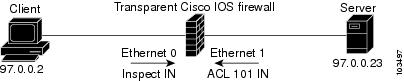
The following example and sample topology (see Figure 1) illustrate how to configure and debug a transparent Cisco IOS Firewall configuration between a client, a firewall, and a server. This example also includes show command output for additional configuration verification. After you have configured a transparent firewall, you can Telnet from the client to the server through the firewall. (See the section "Example: Monitoring Telnet Connections via debug and show Output."
Figure 1 Sample Topology for Transparent Firewall Configuration
Note ![]() Effective with Cisco IOS Release 12.4(20)T, the debug ip inspect command is replaced by the debug policy-firewall command. See the Cisco IOS Debug Command Reference for more information.
Effective with Cisco IOS Release 12.4(20)T, the debug ip inspect command is replaced by the debug policy-firewall command. See the Cisco IOS Debug Command Reference for more information.
! Enable debug commands.
Router# debug ip inspect L2-transparent packet
INSPECT L2 firewall debugging is on
Router# debug ip inspect object-creation
INSPECT Object Creations debugging is on
Router# debug ip inspect object-deletion
INSPECT Object Deletions debugging is on
! Start the transparent firewall configuration process
Router# config terminal
Enter configuration commands, one per line. End with CNTL/Z.
! Configure bridging
Router(config)# bridge 1 protocol ieee
Router(config)# bridge irb
Router(config)# bridge 1 route ip
Router(config)# interface bvi1
*Mar 1 00:06:42.511:%LINK-3-UPDOWN:Interface BVI1, changed state to down.
Router(config-if)# ip address 209.165.200.225 255.255.255.254
! Configure inspection
Router(config)# ip inspect name test tcp
! Following debugs show the memory allocated for CBAC rules.
*Mar 1 00:07:21.127:CBAC OBJ_CREATE:create irc 817F04F0 (test)
*Mar  1 00:07:21.127:CBAC OBJ_CREATE:create irt 818AED20 Protocol:tcp Inactivity time:0
test
Router(config)# ip inspect name test icmp
Router(config)#
*Mar 1 00:07:39.211:CBAC OBJ_CREATE:create irt 818AEDCC Protocol:icmp Inactivity time:0
! Configure Bridging on ethernet0 interface
Router(config)# interface ethernet0
Router(config-if)# bridge-group 1
*Mar 1 00:07:49.071:%LINK-3-UPDOWN:Interface BVI1, changed state to up
*Mar  1 00:07:50.071:%LINEPROTO-5-UPDOWN:Line protocol on Interface BVI1, changed state to
up
! Configure inspection on ethernet0 interface
Router(config-if)# ip inspect test in
Router(config-if)#
*Mar 1 00:07:57.543:CBAC OBJ_CREATE:create idbsb 8189CBFC (Ethernet0)
! Incremented the number of bridging interfaces configured for inspection
*Mar 1 00:07:57.543:L2FW:Incrementing L2FW i/f count
Router(config-if)# interface ethernet1
! Configure bridging and ACL on interface ethernet1
Router(config-if)# bridge-group 1
Router(config-if)# ip access-group 101 in
*Mar  1 00:08:26.711:%LINEPROTO-5-UPDOWN:Line protocol on Interface Ethernet1, changed
state to up
Router(config-if)# end
Router(config)# end
!
! Issue the show running-config command to verify the complete transparent firewall
! configuration.
Router# show running-config
Building configuration...
Current configuration :1126 bytes
!
version 12.3
no service pad
service timestamps debug datetime msec
service timestamps log datetime msec
no service password-encryption
!
hostname Firewall
!
logging buffered 12000 debugging
no logging console
!
no aaa new-model
ip subnet-zero
no ip domain lookup
!
!
ip inspect name test tcp
ip inspect name test icmp
ip audit notify log
ip audit po max-events 100
no ftp-server write-enable
!
!
!
no crypto isakmp enable
!
!
bridge irb
!
!
interface Ethernet0
no ip address
no ip proxy-arp
ip inspect test in
bridge-group 1
hold-queue 100 out
!
interface Ethernet1
no ip address
ip access-group 101 in
no ip unreachables
no ip proxy-arp
duplex auto
bridge-group 1
!
interface BVI1
ip address 209.165.200.225 255.255.255.254
!
ip classless
ip route 9.1.0.0 255.255.0.0 9.4.0.1
no ip http server
no ip http secure-server
!
!
ip access-list log-update threshold 1
access-list 101 permit icmp any any log
access-list 101 deny ip any any log
!
control-plane
!
bridge 1 protocol ieee
bridge 1 route ip
!
line con 0
no modem enable
stopbits 1
line aux 0
stopbits 1
line vty 0 4
login
!
scheduler max-task-time 5000
!
end
!
! Issue show brige commands to check the tables.
Router# show bridge
Total of 300 station blocks, 300 free
Codes:P - permanent, S - self
Bridge Group 1:
! The bridge table is empty because no traffic has been seen
!
Router# show bridge group
Bridge Group 1 is running the IEEE compatible Spanning Tree protocol
Port 2 (Ethernet0) of bridge group 1 is forwarding
Port 3 (Ethernet1) of bridge group 1 is forwarding
! Note that the interfaces are in a "forwarding" state. The interfaces move from
! a listening state to a learning state and finally to a forwarding state. It takes
! approximately 30 seconds to move to a forwarding after "bridge-group 1" is configured.
Example: Monitoring Telnet Connections via debug and show Output
The following examples shows how to monitor established Telnet connections from the client to the server through the firewall (see Figure 1) and from the server to the client. In these example, the debug ip inspect L2-transparent packet command has been issued to generate the debug messages. Relevant show commands are also issued for additional verification.
Note ![]() Effective with Cisco IOS Release 12.4(20)T, the debug ip inspect command is replaced by the debug policy-firewall command. See the Cisco IOS Debug Command Reference for more information.
Effective with Cisco IOS Release 12.4(20)T, the debug ip inspect command is replaced by the debug policy-firewall command. See the Cisco IOS Debug Command Reference for more information.
•![]() Telnet Connection from the Client (97.0.0.2) to the Server (97.0.0.23)
Telnet Connection from the Client (97.0.0.2) to the Server (97.0.0.23)
•![]() Telnet Connection from the Server (97.0.0.23) to the Client (97.0.0.2)
Telnet Connection from the Server (97.0.0.23) to the Client (97.0.0.2)
Telnet Connection from the Client (97.0.0.2) to the Server (97.0.0.23)
The following example is output from the initial Telnet connection between the client and the server. A subsequent connection is established to highlight differences in the debug output. Explanations are given inline.
! A packet is received by the firewall in the flood path because the bridge-table is
! initially empty. However, the client seems to have the server's mac-address in its ARP
! cache, so the bridge floods the packet and it appears in the firewall's "flood" path.
*Mar 1 00:17:32.119:L2FW:insp_l2_flood:input is Ethernet0 output is Ethernet1
! Source and destination IP addresses and the L4 protocol of the packet
*Mar 1 00:17:32.123:L2FW*:Src 97.0.0.2 dst 97.0.0.23 protocol tcp
! ACL processing status. An ACL is not configured in this direction; that is, from the
! client to the server.
*Mar 1 00:17:32.123:L2FW:Input ACL not configured or the ACL is bypassed
*Mar 1 00:17:32.123:L2FW:Output ACL is not configured or ACL is bypassed
! If there are exactly two interfaces in the bridge-group and the packet is in flood path,
! the firewall invokes inspection directly, skipping the Unicast flood algorithm. If there
! are more than 2 interfaces, the firewall "drops" the packet and issues the algorithm.
*Mar  1 00:17:32.123:L2FW:FLOOD number of i/fs in bridge-group is exactly 2. Calling
Inspection
! The packet is being inspected.
*Mar 1 00:17:32.123:L2FW:insp_l2_inspection:input is Ethernet0 output is Ethernet1
*Mar 1 00:17:32.123:L2FW*:Src 97.0.0.2 dst 97.0.0.23 protocol tcp
*Mar 1 00:17:32.123:L2FW:Input ACL not configured or the ACL is bypassed
*Mar 1 00:17:32.123:L2FW:Output ACL is not configured or ACL is bypassed
! Memory is allocated for the transparent firewall attributes in the session structure
*Mar 1 00:17:32.123:L2FW:allocating L2 extension for sis
! CBAC-related debug messages: The packet has been passed to the existing CBAC code.
*Mar  1 00:17:32.123:CBAC Pak 814635DC sis 816C9C24 initiator_addr (97.0.0.2:11016)
responder_addr (97.0.0.23:23)
initiator_alt_addr (97.0.0.2:11016) responder_alt_addr (97.0.0.23:23)
! CBAC session structure has been allocated
*Mar 1 00:17:32.127:CBAC OBJ_CREATE:create sis 816C9C24
*Mar 1 00:17:32.127:CBAC OBJ-CREATE:sid 816D69D8 acl 101 Prot:tcp
*Mar 1 00:17:32.127: Src 97.0.0.23 Port [23:23]
*Mar 1 00:17:32.127: Dst 97.0.0.2 Port [11016:11016]
! The Layer 2 header length is being computed for caching the L2 header, which will be
! used if a TCP RST should be sent in the future to tear down the connection.
*Mar 1 00:17:32.127:L2FW:L2 header length(initiator->responder) is 14
! Checks to see if the header is 802.3, SNAP, SAP. (This header is 802.3.)
*Mar 1 00:17:32.127:L2FW:info_start is NULL for init->rsp
*Mar 1 00:17:32.127:CBAC OBJ_CREATE:create host entry 816D4018 addr 97.0.0.23 bucket 118
! CBAC has indicated that the packet should be passed
*Mar 1 00:17:32.127:L2FW:insp_inspection returned FALSE. PASS
! The next packet in the flow has arrived on the interrupt path. This packet is from the
! server (ethernet1) to the client (ethernet0).
*Mar  1 00:17:32.131:L2FW*:insp_l2_fast_inspection:pak 812C9084, input-interface
Ethernet1, output-interface Ethernet0
*Mar 1 00:17:32.131:L2FW*:Src 97.0.0.23 dst 97.0.0.2 protocol tcp
*Mar 1 00:17:32.131:L2FW:Input ACL not configured or the ACL is bypassed
*Mar 1 00:17:32.131:L2FW:Output ACL is not configured or ACL is bypassed
! The Layer 2 header length is computed and will be cached
*Mar 1 00:17:32.131:L2FW:L2 header length is 14 (rsp->init)
*Mar 1 00:17:32.131:L2FW:info_start is NULL rsp->init
! CBAC has indicated that the packet should be forwarded
*Mar 1 00:17:32.131:L2FW*:insp_l2_fast_inspection returning INSP_L2_OK
! A new packet has arrived from the client. The following trace repeats for each packet
received by the firewall
*Mar  1 00:17:32.135:L2FW*:insp_l2_fast_inspection:pak 81462FB4, input-interface
Ethernet0, output-interface Ethernet1
*Mar 1 00:17:32.135:L2FW*:Src 97.0.0.2 dst 97.0.0.23 protocol tcp
*Mar 1 00:17:32.135:L2FW:Input ACL not configured or the ACL is bypassed
*Mar 1 00:17:32.135:L2FW:Output ACL is not configured or ACL is bypassed
*Mar 1 00:17:32.135:L2FW*:insp_l2_fast_inspection returning INSP_L2_OK
...<more packets >...
! The host entry for the server is deleted.
*Mar 1 00:17:32.263:CBAC OBJ_DELETE:delete host entry 816D4018 addr 97.0.0.23
! Issue the show ip inspect command to verify that a CBAC session has been established
Router# show ip inspect session detailed
Established Sessions
Session 816C9C24 (97.0.0.2:11016)=>(97.0.0.23:23) tcp SIS_OPEN
Created 00:00:28, Last heard 00:00:09
Bytes sent (initiator:responder) [38:75]
In SID 97.0.0.23[23:23]=>97.0.0.2[11016:11016] on ACL 101 (12 matches)
Router#
!
! Issue the show bridge command to verify that entries for the client and server have been
! created in the bridge-table.
Router# show bridge
Total of 300 station blocks, 298 free
Codes:P - permanent, S - self
Bridge Group 1:
Address Action Interface Age RX count TX count
0008.a3b6.b603 forward Ethernet0 2 14 12
0007.0d97.308f forward Ethernet1 2 12 13
Router#
!
! Close the TCP connection (by typing exit at the client).
*Mar 1 00:21:26.259:CBAC OBJ_DELETE:delete sis 816C9C24
*Mar 1 00:21:26.259:CBAC OBJ-DELETE:sid 816D69D8 on acl 101 Prot:tcp
*Mar 1 00:21:26.259: Src 97.0.0.23 Port [23:23]
*Mar 1 00:21:26.259: Dst 97.0.0.2 Port [11016:11016]
! The data structures pertaining to the Layer 2 firewall have been deleted from the
! session. The session has also been deleted.
*Mar 1 00:21:26.259:L2FW:Deleting L2FW data structures
A New Telnet Connection from the Client (97.0.0.2) to the Server (97.0.0.23)
! The initial SYN packet from the client has arrived in the interrupt path. Note that the
! corresponding packet from the previous telnet session came in on the flood path because
! the bridge-table was empty so the bridge was forced to flood the packet. Since the
! bridge-table is now populated, the packet does not not to be flooded. This is the only
! difference between the previous telnet session and this session. Subsequent packets will
! follow the same path (and generate the same debugs) as the previous session.
*Mar  1 00:23:31.883:L2FW*:insp_l2_fast_inspection:pak 81465190, input-interface
Ethernet0, output-interface Ethernet1
*Mar 1 00:23:31.883:L2FW*:Src 97.0.0.2 dst 97.0.0.23 protocol tcp
*Mar 1 00:23:31.883:L2FW:Input ACL not configured or the ACL is bypassed
*Mar 1 00:23:31.883:L2FW:Output ACL is not configured or ACL is bypassed
! CBAC has indicated that the packet should be punted to the process path since memory
! allocation and the control-plane is involved
*Mar 1 00:23:31.883:L2FW*:insp_l2_fast_inspection returning INSP_L2_PUNT
! After being punted from the interrupt path, the packet has arrived at the process level
! for inspection. Moving forward, the debug messages are similar to the flood case in the
! previous session.
*Mar 1 00:23:31.883:L2FW:insp_l2_inspection:input is Ethernet0 output is Ethernet1
*Mar 1 00:23:31.883:L2FW*:Src 97.0.0.2 dst 97.0.0.23 protocol tcp
*Mar 1 00:23:31.883:L2FW:Input ACL not configured or the ACL is bypassed
*Mar 1 00:23:31.883:L2FW:Output ACL is not configured or ACL is bypassed
*Mar 1 00:23:31.887:L2FW:allocating L2 extension for sis
*Mar  1 00:23:31.887:CBAC Pak 81465190 sis 816C9C24 initiator_addr (97.0.0.2:11017)
responder_addr (97.0.0.23:23)
initiator_alt_addr (97.0.0.2:11017) responder_alt_addr (97.0.0.23:23)
*Mar 1 00:23:31.887:CBAC OBJ_CREATE:create sis 816C9C24
*Mar 1 00:23:31.887:CBAC OBJ-CREATE:sid 816D69D8 acl 101 Prot:tcp
*Mar 1 00:23:31.887: Src 97.0.0.23 Port [23:23]
*Mar 1 00:23:31.887: Dst 97.0.0.2 Port [11017:11017]
*Mar 1 00:23:31.887:L2FW:L2 header length(initiator->responder) is 14
*Mar 1 00:23:31.887:L2FW:info_start is NULL for init->rsp
*Mar 1 00:23:31.887:CBAC OBJ_CREATE:create host entry 816D4018 addr 97.0.0.23 bucket 118
! CBAC has indicated that the packet should be Passed
*Mar 1 00:23:31.891:L2FW:insp_inspection returned FALSE. PASS
!
! Issue the show ip inspect command to verify the newly created inspect session
Router# show ip inspect session details
Established Sessions
Session 816C9C24 (97.0.0.2:11017)=>(97.0.0.23:23) tcp SIS_OPEN
Created 00:00:52, Last heard 00:00:37
Bytes sent (initiator:responder) [38:75]
In SID 97.0.0.23[23:23]=>97.0.0.2[11017:11017] on ACL 101 (10 matches)
Router#
Telnet Connection from the Server (97.0.0.23) to the Client (97.0.0.2)
The following sample output is from a Telnet connection that was initiated from the server to the client. This connection will not go through because "ACL 101" is configured to allow only ICMP packets and deny all other packets. Note that inspection is not configured from the server to the client. This example is shown to display the debug messages that are associated with dropped packets.
! The first packet from the server comes in on ethernet1 interface
*Mar  1 00:26:12.367:L2FW*:insp_l2_fast_inspection:pak 815C89FC, input-interface
Ethernet1, output-interface Ethernet0
*Mar 1 00:26:12.367:L2FW*:Src 97.0.0.23 dst 97.0.0.2 protocol tcp
! This packet is punted up since ACL 101 is configured for logging. Logging happens in the
process path. If logging was not configured, the packet would have been dropped instead of
being punted to process level
*Mar 1 00:26:12.367:L2FW:Packet punted up by Input ACL for logging
! The packet arrives at process level
*Mar 1 00:26:12.367:L2FW:insp_l2_inspection:input is Ethernet1 output is Ethernet0
*Mar 1 00:26:12.371:L2FW*:Src 97.0.0.23 dst 97.0.0.2 protocol tcp
! The ACL log is generated
*Mar  1 00:26:12.371:%SEC-6-IPACCESSLOGP:list 101 denied tcp 97.0.0.23(11045) ->
97.0.0.2(23), 1 packet
! The packet is dropped by the ACL
*Mar 1 00:26:12.371:L2FW:Packet processed and dropped by Input ACL
! The packet is dropped by the ACL and is therefore NOT sent to CBAC for inspection
*Mar 1 00:26:12.371:L2FW:Packet is dropped in insp_l2_inspection
Examples: Configuring and Verifying DHCP Pass-Through Traffic
The following examples show how to verify (via debug messages) DHCP pass-through that has been allowed and traffic that has not been allowed.
•![]() Example: Allowing DHCP Pass-Through Traffic
Example: Allowing DHCP Pass-Through Traffic
•![]() Example: Denying DHCP Pass-Through Traffic
Example: Denying DHCP Pass-Through Traffic
Example: Allowing DHCP Pass-Through Traffic
In this example, the static IP address of the client is removed and the address is acquired via DHCP using the ip address dhcp command on the interface that is connected to the transparent firewall.
Router# show debug
ARP:
ARP packet debugging is on
L2 Inspection:
INSPECT L2 firewall debugging is on
INSPECT L2 firewall DHCP debugging is on
Router#
Router#
! Configure DHCP passthrough
Router(config)# ip insp L2-transparent dhcp-passthrough
! The DHCP discover broadcast packet arrives from the client. Since this packet is a
! broadcast (255.255.255.255), it arrives in the flood path
*Mar 1 00:35:01.299:L2FW:insp_l2_flood:input is Ethernet0 output is Ethernet1
*Mar 1 00:35:01.299:L2FW*:Src 0.0.0.0 dst 255.255.255.255 protocol udp
*Mar 1 00:35:01.299:L2FW:udp ports src 68 dst 67
*Mar 1 00:35:01.299:L2FW:src 0.0.0.0 dst 255.255.255.255
! The DHCP pass through flag is checked and the packet is allowed
*Mar 1 00:35:01.299:L2FW:DHCP packet seen. Pass-through flag allows the packet
! The packet is a broadcast packet and therefore not sent to CBAC
*Mar 1 00:35:01.299:L2FW*:Packet is broadcast or multicast.PASS
! The DHCP server 97.0.0.23 responds to the client's request
*Mar 1 00:35:01.303:L2FW:insp_l2_flood:input is Ethernet1 output is Ethernet0
*Mar 1 00:35:01.303:L2FW*:Src 97.0.0.23 dst 255.255.255.255 protocol udp
*Mar 1 00:35:01.307:L2FW:udp ports src 67 dst 68
*Mar 1 00:35:01.307:L2FW:src 97.0.0.23 dst 255.255.255.255
*Mar 1 00:35:01.307:L2FW:DHCP packet seen. Pass-through flag allows the packet
*Mar 1 00:35:01.307:L2FW*:Packet is broadcast or multicast.PASS
*Mar 1 00:35:01.311:L2FW:insp_l2_flood:input is Ethernet0 output is Ethernet1
*Mar 1 00:35:01.311:L2FW*:Src 0.0.0.0 dst 255.255.255.255 protocol udp
*Mar 1 00:35:01.311:L2FW:udp ports src 68 dst 67
*Mar 1 00:35:01.311:L2FW:src 0.0.0.0 dst 255.255.255.255
*Mar 1 00:35:01.315:L2FW:DHCP packet seen. Pass-through flag allows the packet
*Mar 1 00:35:01.315:L2FW*:Packet is broadcast or multicast.PASS
*Mar 1 00:35:01.315:L2FW:insp_l2_flood:input is Ethernet1 output is Ethernet0
*Mar 1 00:35:01.323:L2FW*:Src 97.0.0.23 dst 255.255.255.255 protocol udp
*Mar 1 00:35:01.323:L2FW:udp ports src 67 dst 68
*Mar 1 00:35:01.323:L2FW:src 97.0.0.23 dst 255.255.255.255
*Mar 1 00:35:01.323:L2FW:DHCP packet seen. Pass-through flag allows the packet
*Mar 1 00:35:01.323:L2FW*:Packet is broadcast or multicast.PASS
! The client has an IP address (97.0.0.5) and has issued a G-ARP to let everyone know it's
address
*Mar 1 00:35:01.327:IP ARP:rcvd rep src 97.0.0.5 0008.a3b6.b603, dst 97.0.0.5 BVI1
Router#
Example: Denying DHCP Pass-Through Traffic
In this example, DHCP pass-through traffic is not allowed (via the no ip inspect L2-transparent dhcp-passthrough command). The client is denied when it attempts to acquire a DHCP address from the server.
! Deny DHCP pass-through traffic
Router(config)# no ip inspect L2-transparent dhcp-passthrough
! The DHCP discover broadcast packet arrives from the client
*Mar 1 00:36:40.003:L2FW:insp_l2_flood:input is Ethernet0 output is Ethernet1
*Mar 1 00:36:40.003:L2FW*:Src 0.0.0.0 dst 255.255.255.255 protocol udp
*Mar 1 00:36:40.003:L2FW:udp ports src 68 dst 67
*Mar 1 00:36:40.007:L2FW:src 0.0.0.0 dst 255.255.255.255
! The pass-through flag is checked
*Mar 1 00:36:40.007:L2FW:DHCP packet seen. Pass-through flag denies the packet
! The packet is dropped because the flag does not allow DHCP passthrough traffic. Thus,
! the client cannot acquire an address, and it times out
*Mar 1 00:36:40.007:L2FW:FLOOD Dropping the packet after ACL check.
Router#
Additional References
Related Documents
Standards
|
|
|
|---|---|
No new or modified standards are supported by this feature, and support for existing standards has not been modified by this feature. |
— |
MIBs
RFCs
|
|
|
|---|---|
No new or modified RFCs are supported by this feature, and support for existing RFCs has not been modified by this feature. |
— |
Technical Assistance
Feature Information for Transparent Cisco IOS Firewall
Table 1 lists the features in this module and provides links to specific configuration information.
Use Cisco Feature Navigator to find information about platform support and software image support. Cisco Feature Navigator enables you to determine which software images support a specific software release, feature set, or platform. To access Cisco Feature Navigator, go to http://www.cisco.com/go/cfn. An account on Cisco.com is not required.
Note ![]() Table 1 lists only the software release that introduced support for a given feature in a given software release train. Unless noted otherwise, subsequent releases of that software release train also support that feature.
Table 1 lists only the software release that introduced support for a given feature in a given software release train. Unless noted otherwise, subsequent releases of that software release train also support that feature.
Cisco and the Cisco Logo are trademarks of Cisco Systems, Inc. and/or its affiliates in the U.S. and other countries. A listing of Cisco's trademarks can be found at www.cisco.com/go/trademarks. Third party trademarks mentioned are the property of their respective owners. The use of the word partner does not imply a partnership relationship between Cisco and any other company. (1005R)
Any Internet Protocol (IP) addresses and phone numbers used in this document are not intended to be actual addresses and phone numbers. Any examples, command display output, network topology diagrams, and other figures included in the document are shown for illustrative purposes only. Any use of actual IP addresses or phone numbers in illustrative content is unintentional and coincidental.
© 2009 Cisco Systems, Inc. All rights reserved.
 Feedback