Cisco CRS 3-Phase AC Power Distribution Unit Installation Guide
Available Languages
Contents
- Cisco CRS 3-Phase AC Power Distribution Unit Installation Guide
- Cisco CRS 3-Phase AC Power Distribution Unit
- Documentation and Resources
- Document Revision History
- Documentation Forum
- Obtaining Documentation and Submitting a Service Request
- Overview
- Cisco CRS PDU Kit for Cisco CRS 8-Slot Line Card Chassis
- Cisco CRS PDU Kit for Cisco CRS 16-Slot Line Card Chassis
- Cisco CRS PDU Kit for Cisco CRS Fabric Card Chassis
- Safety Warnings
- General Power and Grounding Requirements
- Installing or Removing the PDU Kit
- Cisco CRS PDU Kit for Cisco CRS 8-Slot Line Card Chassis
- Installing the PDU Kit
- Required Tools and Equipment
- Steps
- What to Do Next
- Removing the PDU Kit
- Required Tools and Equipment
- Steps
- Installing a Single PDU in a Cisco CRS-8 PDU Kit
- Prerequisites
- Required Tools and Equipment
- Steps
- Removing a Single PDU from a Cisco CRS-8 PDU Kit
- Prerequisites
- Required Tools and Equipment
- Steps
- Installing PDU Kit in Rack
- Prerequisites
- Required Tools and Equipment
- Steps
- Removing PDU Kit from Rack
- Prerequisites
- Required Tools and Equipment
- Steps
- Installing PDU Kit to Side of Cisco CRS 16-Slot Line Card Chassis
- Prerequisites
- Required Tools and Equipment
- Steps
- Removing PDU Kit from Side of Cisco CRS 16-Slot Line Card Chassis
- Prerequisites
- Required Tools and Equipment
- Steps
- Installing PDU Kit to Side of Cisco CRS Fabric Card Chassis
- Prerequisites
- Required Tools and Equipment
- Steps
- Removing PDU Kit from Side of Chassis
- Prerequisites
- Required Tools and Equipment
- Steps
- Specifications
Cisco CRS 3-Phase AC Power Distribution Unit Installation Guide
Cisco CRS 3-Phase AC Power Distribution Unit
Documentation and Resources
Documentation for the Cisco CRS Power Distribution Unit (PDU) is online with the exception of the regulatory compliance and safety information documentation. For a complete listing of Cisco CRS planning, installation, and configuration documents, see the Cisco CRS Carrier Routing System Hardware Documentation Guide .
Document Revision History
The Document Revision History table below records technical changes to this document.
Document Version
Date
Change Summary
OL-23476-03
July 2011
Added technical information and new procedures for installing and removing a Cisco CRS PDU kit on a Cisco CRS fabric card chassis. New AC cord clamp information was added. Minor technical and editorial updates were made.
OL-23476-02
November 2010
This document was updated with technical corrections. Document updates to specifications, and installation and removal procedures.
OL-23476-01
September 2010
First version of this document.
Documentation Forum
Suggest ways Cisco technical documentation can be improved and better serve your needs.
Participate in the Technical Documentation Ideas forum.
Obtaining Documentation and Submitting a Service Request
For information on obtaining documentation, submitting a service request, and gathering additional information, see the monthly What’s New in Cisco Product Documentation , which also lists all new and revised Cisco technical documentation, at:
http://www.cisco.com/en/US/docs/general/whatsnew/whatsnew.html
Subscribe to the What’s New in Cisco Product Documentation as a Really Simple Syndication (RSS) feed and set content to be delivered directly to your desktop using a reader application. The RSS feeds are a free service and Cisco currently supports RSS version 2.0.
Overview
This section describes the Cisco CRS Power Distribution Unit (PDU). The PDU converts 3-phase AC input power to single-phase AC output power that connects directly to the rear of the modular configuration AC power shelf.
Note
The PDU referred to in this document is different from the fixed configuration PDU.The AC PDU includes either an AC Delta or AC Wye power interface, and has power input and power output cords entering and exiting the box. The PDU can be installed in a 19-inch rack or other locations, depending on the PDU type, by using chassis mounting brackets.
In this document, single PDU refers to the individual PDU that converts 3-phase AC input power to single-phase AC output power. Cisco product numbers for single PDUs are as follows:
- PDU-321-3-Delta—3-phase to single-phase AC Delta PDU, 1 input/3 output
- PDU-321-3-Wye—3-phase to single-phase AC Wye PDU, 1 input/3 output
- PDU-321-6-Delta—3 phase to single-phase AC Delta PDU, 2 input/6 output
- PDU-321-6-Wye—3-phase to single-phase AC Wye PDU, 1 input/6 output
A PDU kit refers to all the components that are required to be installed in a redundant Cisco CRS system. A PDU kit contains 2 single PDUs and any necessary mounting brackets or hardware. When ordering a Cisco CRS system, a PDU kit Cisco product number should be ordered. Cisco product numbers for PDU kits are as follows:
- CRS-8-PDU-Delta—Redundant 3-phase to single-phase Delta PDU for Cisco CRS 8-slot line card chassis, 2 input/6 output
- CRS-8-PDU-Wye—Redundant 3-phase to single-phase Wye PDU for Cisco CRS 8-slot line card chassis, 2 input/6 output
- CRS-16-PDU-Delta—Redundant 3-phase to single-phase Delta PDU for Cisco CRS 16-slot line card chassis, 4 input/12 output
- CRS-16-PDU-Wye—Redundant 3-phase to single-phase Wye PDU for Cisco CRS 16-slot line card chassis, 2 input/12 output
- CRS-FCC-PDU Delta—Redundant 3-phase to single-phase Delta PDU for Cisco CRS fabric card chassis, 4 input/12 output
- CRS-FCC-PDU Wye—Redundant 3-phase to single-phase Wye PDU for Cisco CRS fabric card chassis, 2 input/12 output
Cisco CRS PDU Kit for Cisco CRS 8-Slot Line Card Chassis
This section describes the Cisco CRS PDU kit for the Cisco CRS 8-slot line card chassis. The PDU has power input and power output cords entering and exiting the box. One single PDU is required for each modular configuration AC power shelf installed in the chassis for system redundancy. Each PDU kit consists of two identical single PDUs, either AC Delta (Cisco product number PDU-321-3-Delta) or AC Wye (Cisco product number PDU-321-3-Wye), installed in a 19-inch rack tray (Cisco product number CRS-8-PDU-tray). One PDU kit is required to be installed for system redundancy.
Note
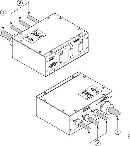
In order to maintain a balanced 3-phase power load, three AC power modules (PMs) are required to be installed in a Cisco CRS 8-slot line card chassis AC modular configuration power shelf.This figure shows the single Delta PDU (Cisco product number PDU-321-3-Delta). The single Wye PDU (Cisco product number PDU-321-3-Wye) is similar.
1
3-phase AC input cord
2
Single-phase AC output cords
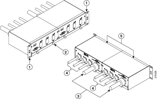
This figure shows the Delta PDU kit that converts 3-phase AC input power to single-phase AC output power for the Cisco CRS 8-slot line card chassis.
1
Rack mounting brackets
4
Single-phase AC output cords
2
Rack tray (Cisco product number CRS-8-PDU-tray=)
5
Two PDUs (Cisco product number PDU-321-3-Delta)
3
3-phase AC input cords
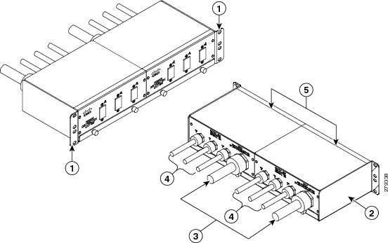
This figure shows the Wye PDU kit that converts 3-phase AC input power to single-phase AC output power for the Cisco CRS 8-slot line card chassis.
1
Rack mounting brackets
4
Single-phase AC output cords
2
Rack tray (Cisco product number CRS-8-PDU-tray=)
5
Two PDUs (Cisco product number PDU-321-3-Wye)
3
3-phase AC input cords
Cisco CRS PDU Kit for Cisco CRS 16-Slot Line Card Chassis
This section describes the Cisco CRS PDU kit for the Cisco CRS 16-slot line card chassis.
The PDU has power input and power output cords entering and exiting the box. One single PDU is required for each modular configuration AC power shelf installed in the chassis for system redundancy. Each PDU kit includes two single PDUs, either AC Delta (Cisco product number PDU-321-6-Delta) or AC Wye (Cisco product number PDU-321-6-Wye), with 19-inch rack-mounting brackets pre-installed, and chassis mounting brackets for alternative mounting. The left and right chassis mounting brackets are not shipped pre-installed on the PDU. For information on how to install the PDU to the side of the Cisco CRS 16-slot line card chassis, see the Installing PDU Kit to Side of Cisco CRS 16-Slot Line Card Chassis.
Note
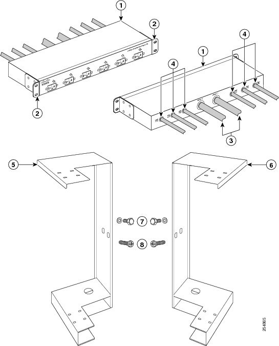
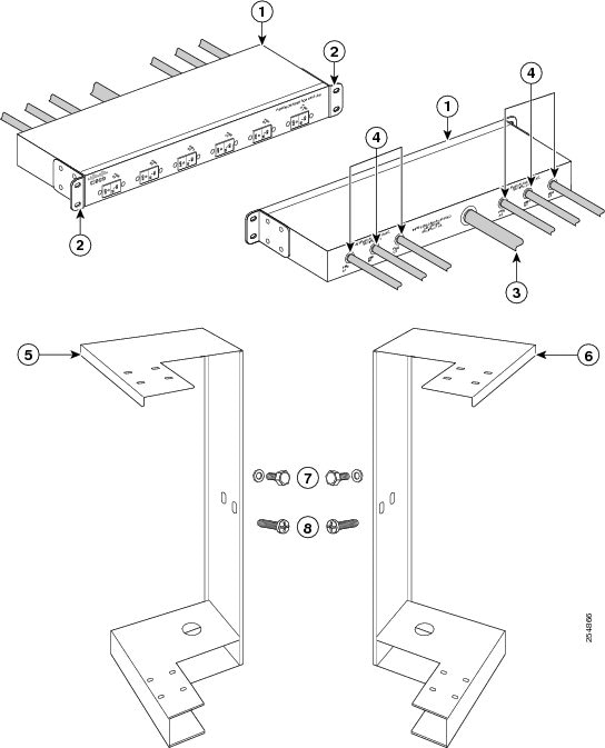
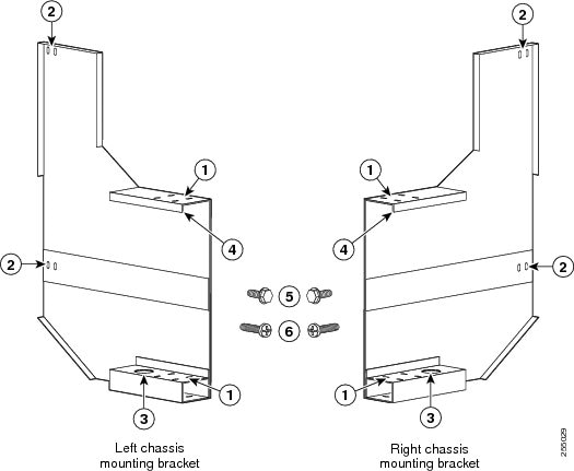
In order to maintain a balanced 3-phase power load, six AC PMs are required to be installed in a Cisco CRS 16-slot line card chassis or Cisco CRS 16-slot line card chassis AC modular configuration power shelf.This figure shows the Delta PDU kit that converts 3-phase AC input power to single-phase AC output power and chassis mounting brackets for the Cisco CRS 16-slot line card chassis. For more information, see the Installing PDU Kit to Side of Cisco CRS 16-Slot Line Card Chassis.
1
AC Delta PDU (PDU-321-6-Delta) quantity=2, 1 shown
5
Left chassis mounting bracket
2
Removable 19-inch rack mounting brackets
6
Right chassis mounting bracket
3
3-phase AC input cords (permanently attached)
7
M8 hex head bolt and M8 flat washer, two per bracket
4
Single-phase AC output cords (permanently attached)
8
Pan head screw, eight per bracket
This figure shows the Wye PDU kit that converts 3-phase AC input power to single-phase AC output power and chassis mounting brackets for the Cisco CRS 16-slot line card chassis. For more information, see the Installing PDU Kit to Side of Cisco CRS 16-Slot Line Card Chassis.
1
AC Wye PDU (PDU-321-6-Wye) quantity=2, 1 shown
5
Left chassis mounting bracket
2
Removable 19-inch rack mounting brackets
6
Right chassis mounting bracket
3
3-phase AC input cord (permanently attached)
7
M8 hex head bolt and M8 flat washer, two per bracket
4
Single-phase AC output cords (permanently attached)
8
Pan head screw, eight per bracket
Cisco CRS PDU Kit for Cisco CRS Fabric Card Chassis
This section describes the Cisco CRS PDU kit for the Cisco CRS fabric card chassis.
The PDU has power input and power output cords entering and exiting the box. One single PDU is required for each modular configuration AC power shelf installed in the chassis for system redundancy. Each PDU kit includes two single PDUs, either AC Delta (Cisco product number PDU-321-6-Delta) or AC Wye (Cisco product number PDU-321-6-Wye), with 19-inch rack-mounting brackets pre-installed, and chassis mounting brackets for alternative mounting. The left and right chassis mounting brackets are not shipped pre-installed on the PDU. For information on how to install the PDU to the side of the Cisco CRS fabric card chassis see the .Installing PDU Kit to Side of Cisco CRS Fabric Card Chassis
Note
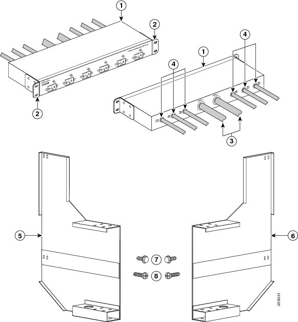
In order to maintain a balanced 3-phase power load, either three or six AC PMs are required to be installed in a Cisco CRS fabric card chassis AC modular configuration power shelf. If only three AC PMs are required in each power shelf, they must be installed in either slots 0, 1, 2 or slots 3,4,5.This figure shows the Delta PDU kit that converts 3-phase AC input power to single-phase AC output power and chassis mounting brackets for the Cisco CRS fabric card chassis. For more information, see the Installing PDU Kit to Side of Cisco CRS Fabric Card Chassis.
1
AC Delta PDU (PDU-321-6-Delta) quantity=2, 1 shown
5
Left chassis mounting bracket
2
Removable 19-inch rack mounting brackets
6
Right chassis mounting bracket
3
3-phase AC input cords (permanently attached)
7
M8 hex head bolt with integrated washer, four per bracket
4
Single-phase AC output cords (permanently attached)
8
Pan head screw, eight per bracket
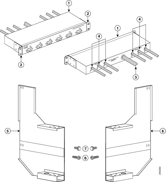
This figure shows the Wye PDU kit that converts 3-phase AC input power to single-phase AC output power and chassis mounting brackets for the Cisco CRS fabric card chassis. For more information, see the Installing PDU Kit to Side of Cisco CRS Fabric Card Chassis.
1
AC Wye PDU (PDU-321-6-Wye) quantity=2, 1 shown
5
Left chassis mounting bracket
2
Removable 19-inch rack mounting brackets
6
Right chassis mounting bracket
3
3-phase AC input cord (permanently attached)
7
M8 hex head bolt with integrated washer, four per bracket
4
Single-phase AC output cords (permanently attached)
8
Pan head screw, eight per bracket
Safety Warnings
These warnings are translated into several languages in Regulatory Compliance and Safety Information for the Cisco CRS Power Distribution Unit that is shipped with the Cisco CRS PDU.
Warning
This equipment is intended to be grounded. Ensure that the host is connected to earth ground during normal use. Statement 39
Note
In statement 39, host refers to the rack or chassis that the Cisco CRS PDU is mounted to.
Warning
This product relies on the building’s installation for short-circuit (overcurrent) protection. Ensure that the protective device is rated not greater than: 250 V/60 A—CRS-8-PDU-Delta=415 V/16 A— CRS-8-PDU-Wye=250 V/60 A—CRS-16-PDU-Delta=415 V/32 A— CRS-16-PDU-Wye=250 V/60 A—CRS-FCC-PDU-Delta=415 V/32 A— CRS-FCC-PDU-Wye= Statement 1005
Warning
To prevent bodily injury when mounting or servicing this unit in a rack, you must take special precautions to ensure that the system remains stable. The following guidelines are provided to ensure your safety:This unit should be mounted at the bottom of the rack if it is the only unit in the rack.When mounting this unit in a partially filled rack, load the rack from the bottom to the top with the heaviest component at the bottom of the rack.If the rack is provided with stabilizing devices, install the stabilizers before mounting or servicing the unit in the rack. Statement 1006
Warning
Take care when connecting units to the supply circuit so that wiring is not overloaded. Statement 1018
Warning
The plug-socket combination must be accessible at all times, because it serves as the main disconnecting device. Statement 1019
Warning
This unit might have more than one power supply connection. All connections must be removed to de-energize the unit. Statement 1028
Warning
This product requires short-circuit (overcurrent) protection, to be provided as part of the building installation. Install only in accordance with national and local wiring regulations. Statement 1045
Warning
To prevent the system from overheating, do not operate it in an area that exceeds the maximum recommended ambient temperature of:40°C (131°F) Statement 1047
Warning
Stability hazard. The rack stabilizing mechanism must be in place, or the rack must be bolted to the floor before you slide the unit out for servicing. Failure to stabilize the rack can cause the rack to tip over. Statement 1048
General Power and Grounding Requirements
This section describes the power and grounding requirements you must consider when planning the site facilities for the PDU.
Note
A certified electrician should review the information in these sections to ensure that the installation site meets these requirements. For larger system configurations, consult a facilities electrical expert to determine the load that the routing system may put on the facility power plant.
- Installation of the PDU must follow national and local electrical codes:
- In the United States—United States National Fire Protection Association (NFPA) 70 and United States National Electrical Code (NEC)
- In Canada—Canadian Electrical Code, part I, CSA C22.1
- In other countries—International Electrotechnical Commission (IEC) 60364, parts 1 through 7
- Two separate and independent AC power sources are needed to provide 2N redundancy for system power. Each power source requires its own circuit breaker.
- Each power source must provide clean power to the site. If necessary, install a power conditioner.
- Site must provide short-circuit (over-current) protection for devices.
- Proper grounding is required at the site to ensure that equipment is not damaged by lightning and power surges. In addition, a grounding-type AC power outlet is required for AC-powered systems.
- Include power requirements for any external terminals and test equipment used with your system when planning for the power for the site.
Note
Review the safety warnings in Regulatory Compliance and Safety Information for the Cisco CRS Power Distribution Unit before attempting to install the routing systemInstalling or Removing the PDU Kit
This section describes how to install an AC Delta or AC Wye PDU kit on the following Cisco CRS chassis types:
Note
Review the safety warnings in Regulatory Compliance and Safety Information for the Cisco CRS Power Distribution Unit before attempting to install the Cisco CRS PDU.
CautionIf the chassis is not properly grounded, refer to Cisco CRS Carrier Routing System 8-Slot Line Card Chassis Installation Guide , Cisco CRS Carrier Routing System 16-Slot Line Card Chassis Installation Guide or Cisco CRS Carrier Routing System Fabric Card Chassis Installation Guide for proper ground bonding instructions.
CautionAll field replaceable units (FRUs) and blank covers must be properly installed in the system.
Cisco CRS PDU Kit for Cisco CRS 8-Slot Line Card Chassis
This section describes how to install or remove a PDU kit in the Cisco CRS 8-slot line card chassis rack.
The procedure for installing or removing a PDU kit is the same for the AC Delta and AC Wye PDU. This section contains the following procedures:
Installing the PDU Kit
This section describes how to install an AC Delta or AC Wye PDU kit in the 19-inch Cisco CRS 8-slot line card chassis rack.
Note
Although there are differences between the AC Delta and AC Wye PDU, they are installed in the same manner.
CautionBefore you begin this procedure, ensure that all power is disconnected from the Cisco CRS PDU. Remove the PDU input plug(s) from the branch circuit outlet(s).
Before you install the PDU kit, be aware of the following:
- If installed in a closed or multi-unit rack assembly, the operating ambient temperature of the rack environment may be greater than room ambient temperature. Therefore, consideration should be given to installing the equipment in an environment compatible with the maximum ambient temperature. See Table 3
- Installation of the equipment in a rack should be such that the amount of air flow required for safe operation of the equipment is not compromised.
- Mounting of the equipment in the rack should be such that a hazardous condition is not achieved due to uneven mechanical loading.
- Consideration should be given to the connection of the equipment to the supply circuit, and to the effect that overloading of the circuits might have on overcurrent protection and supply wiring. Appropriate consideration of equipment nameplate ratings should be used when addressing this concern.
- Reliable earthing of rack-mounted equipment should be maintained. Pay particular attention to supply connections other than direct connections to the branch circuit (e.g. use of power strips).
Required Tools and Equipment
The following tools are required to install the PDU kit:
- Appropriate tool; dependent upon type of rack-mounting screws used
- Number 1 x 6 in. Phillips screwdriver
- PDU kit
- AC Delta PDU kit (Cisco product number CRS-8-PDU-Delta=), or
- AC Wye PDU kit (Cisco product number CRS-8-PDU-Wye=)
Note
You can use an offset number 1 Phillips screwdriver to tighten the AC cord clamp that was available pre-June 2011, but this is optional. The offset screwdriver is in addition to, not instead of, the straight screwdriver. An offset screwdriver is not required to tighten the AC cord clamp that is available from June 2011 onwards.
Note
Rack-mounting screws are not shipped with the PDU kit. You can use 10-32, 10-24, 12-24, or M5 screws. (M6 and 1/4-20 screws do not fit.)Steps
ProcedureTo install the PDU kit in the 19-inch rack, perform the following steps:
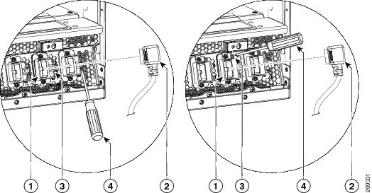
Step 1 Align the rack-mounting bracket holes on the PDU kit with the holes on the vertical rack posts. Step 2 Insert and partially tighten the four screws—two on each side—to attach the rack-mounting brackets on the PDU kit to the vertical rack brackets. See the below figure. Step 3 Use the appropriate tool to fully tighten the screws. Step 4 Connect the output cords on the PDU to the rear of the Cisco CRS 8-slot line card chassis modular configuration AC power shelf.
Note Each output cord on the PDU has a label that designates into which socket it should be plugged (PM0, PM1, and so on).
1
Cord clamp
3
Screw that secures cord
2
Cord to be inserted into clamp
4
Screwdriver that tightens screw
Note In the above figure, the cord clamp shown on the left was available until June 2011, and the cord clamp shown on the right is available from June 2011onwards. The location of the screw that secures the cord in the cord clamp is different. Step 5 Use the number 1 Phillips screwdriver to tighten the screw that clamps the cord in place.
Note You can use an offset number 1 Phillips screwdriver if there is not sufficient clearance for a straight screwdriver. Step 6 Plug the PDU AC input plug into the facility power to energize the Cisco CRS 8-slot line card chassis.
Removing the PDU Kit
This section describes how to remove an AC Delta or AC Wye PDU kit from the Cisco CRS 8-slot line card chassis rack.
Note
Although there are differences between the AC Delta and AC Wye PDU, they are removed in the same manner.
CautionBefore you begin this procedure, ensure that all power is disconnected from the Cisco CRS PDU. Remove the PDU input plug(s) from the branch circuit outlet(s).
Required Tools and Equipment
The following tools are required to remove the PDU kit from the Cisco CRS 8-slot line card chassis rack:
- Appropriate tool; dependent upon type of rack-mounting screw used
- Number 1 x 6 in. Phillips screwdriver
Note
You can use an offset number 1 Phillips screwdriver to loosen the AC cord clamp that was available pre-June 2011, but this is optional. The offset screwdriver is in addition to, not instead of, the straight screwdriver. An offset screwdriver is not required to tighten the AC cord clamp that is available from June 2011 onwards.Steps
ProcedureTo remove the PDU kit from the 19-inch rack, perform the following steps:
Step 1 To disconnect the PDU output cords from the rear of the Cisco CRS 8-slot line card chassis modular configuration AC power shelf, use the number 1 Phillips screwdriver to loosen the screw that clamps the cord in place and remove the cord. See the below figure.
Note You can use an offset number 1 Phillips screwdriver if there is not sufficient clearance for a straight screwdriver.
1
Cord clamp
3
Screw that secures cord clamp
2
Cord removed from clamp
4
Screwdriver that loosens screw
Note In the above figure, the cord clamp shown on the left was available until June 2011, and the cord clamp shown on the right is available from June 2011onwards. The location of the screw that secures the cord in the cord clamp is different. Step 2 Use the appropriate tool to remove the four screws—two on each side—that attach the rack-mounting brackets on the PDU kit to the vertical rack brackets. Step 3 Carefully remove the PDU kit from the rack.
Installing a Single PDU in a Cisco CRS-8 PDU Kit
This section describes how to install a single AC Delta or AC Wye PDU in the 19-inch rack tray.
Note
Although there are differences between the AC Delta and AC Wye PDU, they are installed in the same manner.Prerequisites
CautionBefore you begin this procedure, ensure that power is disconnected from the Cisco CRS PDU being installed. Remove the PDU input plug from the branch circuit outlet.
Required Tools and Equipment
The following tool is required to install a single PDU in the 19-inch rack tray:
- Number 1 x 6 in. Phillips screwdriver
Note
You can use an offset number 1 Phillips screwdriver to tighten the AC cord clamp that was available pre-June 2011, but this is optional. The offset screwdriver is in addition to, not instead of, the straight screwdriver. An offset screwdriver is not required to tighten the AC cord clamp that is available from June 2011 onwards.Steps
ProcedureTo install the single PDU from the 19-inch rack tray, perform the following steps:
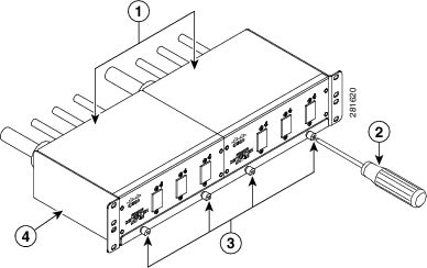
Step 1 Position the PDU and associated power cords in the 19-inch rack tray. Step 2 Use the number 1 Phillips screwdriver to fasten the four panel fasteners (two at front and two at rear) that retain the single PDU in the 19-inch rack tray. The below figure shows the panel fasteners on the front of the 19-inch rack tray.
1
Two single PDUs installed in 19-inch tray
3
Four panel fasteners on front of 19-inch rack tray
2
Screwdriver that tightens panel fastener
4
19-inch rack tray
Step 3 Connect the output cords on the PDU being installed to the rear of the Cisco CRS 8-slot line card chassis modular configuration AC power shelf.
Note Each output cord on the PDU has a label that designates into which socket it should be plugged (PM0, PM1, and so on).
1
Cord clamp
3
Screw that secures cord clamp
2
Cord to be inserted into clamp
4
Screwdriver that tightens screw
Note In the above figure, the cord clamp shown on the left was available until June 2011, and the cord clamp shown on the right is available from June 2011onwards. The location of the screw that secures the cord in the cord clamp is different. Step 4 Use the number 1 Phillips screwdriver to tighten the screw that clamps the cord in place.
Note You can use an offset number 1 Phillips screwdriver if there is not sufficient clearance for a straight screwdriver. Step 5 Plug the PDU AC input plug into the facility power to energize the Cisco CRS 8-slot line card chassis.
Removing a Single PDU from a Cisco CRS-8 PDU Kit
This section describes how to remove a single AC Delta or AC Wye PDU from the 19-inch rack tray.
Note
Although there are differences between the AC Delta and AC Wye PDU, they are removed in the same manner.Prerequisites
Caution
Before you begin this procedure, ensure that power is disconnected from the Cisco CRS PDU being replaced. Remove the PDU input plug from the branch circuit outlet.
Required Tools and Equipment
The following tool is required to remove a single PDU from the 19-inch rack tray:
- Number 1 x 6 in. Phillips screwdriver
Note
You can use an offset number 1 Phillips screwdriver to loosen the AC cord clamp that was available pre-June 2011, but this is optional. The offset screwdriver is in addition to, not instead of, the straight screwdriver. An offset screwdriver is not required to tighten the AC cord clamp that is available from June 2011 onwards.Steps
ProcedureTo remove the single PDU from the 19-inch rack tray, perform the following steps:
Step 1 Disconnect the output cords on the PDU being removed from the rear of the Cisco CRS 8-slot line card chassis modular configuration AC power shelf. Use the number 1 Phillips screwdriver to loosen the screw that clamps the cord in place and remove the cord.
Note You can use an offset number 1 Phillips screwdriver if there is not sufficient clearance for a straight screwdriver.
1
Cord clamp
3
Screw that secures cord clamp
2
Cord removed from clamp
4
Screwdriver that loosens screw
Note In the above figure, the cord clamp shown on the left was available until June 2011, and the cord clamp shown on the right is available from June 2011onwards. The location of the screw that secures the cord in the cord clamp is different. Step 2 Use the number 1 Phillips screwdriver to unfasten only the four panel fasteners (two on front and two on rear) that retain the single PDU you want to remove in the 19-inch rack tray. The below figure shows the panel fasteners on the front of the 19-inch rack tray.
1
Two single PDUs installed in 19-inch tray
3
Four panel fasteners on front of 19-inch rack tray
2
Screwdriver that loosens panel fastener
4
19-inch rack tray
Step 3 Remove the PDU and associated power cords from the 19-inch rack tray.
Installing PDU Kit in Rack
This section describes how to install an AC Delta (PDU-321-6-Delta) or AC Wye PDU (PDU-321-6-Wye) in a 19-inch rack.
Note
Although there are differences between the AC Delta and AC Wye PDU, they are installed in the same manner.Prerequisites
Caution
Before you begin this procedure, ensure that all power is disconnected from the Cisco CRS PDU. Remove the PDU input plug(s) from the branch circuit outlet(s).
Before you install the PDU, be aware of the following:
- If installed in a closed or multi-unit rack assembly, the operating ambient temperature of the rack environment may be greater than room ambient. Therefore, consideration should be given to installing the equipment in an environment compatible with the maximum ambient temperature.
- Installation of the equipment in a rack should be such that the amount of air flow required for safe operation of the equipment is not compromised.
- Mounting of the equipment in the rack should be such that a hazardous condition is not achieved because of uneven mechanical loading.
- Consideration should be given to the connection of the equipment to the supply circuit, and to the effect that overloading of the circuits might have on overcurrent protection and supply wiring. Appropriate consideration of equipment nameplate ratings should be used when addressing this concern.
- Reliable earthing of rack-mounted equipment should be maintained. Particular attention should be given to supply connections other than direct connections to the branch circuit (for example, use of power strips).
Required Tools and Equipment
The following tools are required to install the PDU in a rack:
- Appropriate tool, dependent on the type of rack-mounting screw used
- Number 1 x 6 in. Phillips screwdriver
- PDU kit
- AC Delta PDU kit (Cisco product number CRS-16-PDU-Delta=), or
- AC Wye PDU kit (Cisco product number CRS-16-PDU-Wye=)
Note
Rack mounting screws are not shipped with the PDU kit. Use 10-32, 10-24, 12-24, or M5 screws. (M6 and 1/4-20 screws do not fit.)Steps
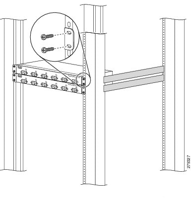
ProcedureTo install the PDU in the 19-inch rack, perform the following steps:
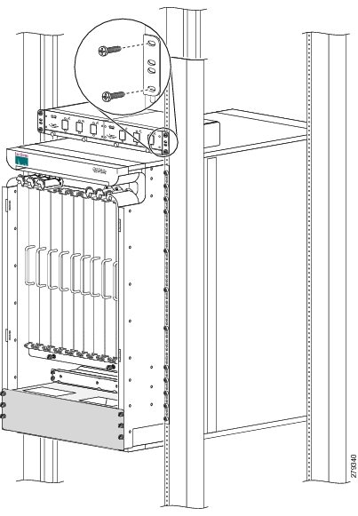
Step 1 Align the rack-mounting bracket holes on the PDU with the holes on the vertical rack posts. Step 2 Insert and partially tighten the four screws—two on each side—to attach the rack mounting brackets on the PDU to the rack vertical mounting brackets. The below figure shows two PDUs being installed in a 19-inch rack. Step 3 Use the appropriate tool to fully tighten the screws. Step 4 Connect the output cords on the PDU to the rear of the modular configuration AC power shelf on the Cisco CRS 16-slot line card chassis or Cisco CRS fabric card chassis.
Note Each output cord on the PDU has a label that designates into which socket it should be plugged (PM0, PM1, and so on).
1
Screw that secures the cord clamp
3
Cord to be inserted into clamp
2
Screwdriver tightening screw
Note In the above figure, the cord clamp shown on the left was available until June 2011, and the cord clamp shown on the right is available from June 2011onwards. The location of the screw that secures the cord in the cord clamp is different. Step 5 Use the number 1 Phillips screwdriver to tighten the screw that clamps the cord in place. Step 6 Plug the PDU AC input plug into the facility power to energize the Cisco CRS 16-slot line card chassis or Cisco CRS fabric card chassis.
What to Do Next
After the installation of the PDU is complete, you can power up the power modules and the chassis and put the Cisco CRS 16-slot line card chassis or Cisco CRS fabric card chassis router into service. See Cisco CRS Carrier Routing System 16-Slot Line Card Chassis Installation Guide or Cisco CRS Carrier Routing System Fabric Card Chassis Installation Guide for more information.
Removing PDU Kit from Rack
This section describes how to remove an AC Delta (PDU-321-6-Delta) or AC Wye PDU (PDU-321-6-Wye) from a 19-inch rack.
Note
Although there are differences between the AC Delta and AC Wye PDU, they are removed in the same manner.Prerequisites
Caution
Before you begin this procedure, ensure that all power is disconnected from the Cisco CRS PDU. Remove the PDU input plug(s) from the branch circuit outlet(s).
Required Tools and Equipment
The following tools are required to install the PDU:
- Appropriate tool, dependent on the type of bolt used to install the PDU
- Number 1 x 6 in. Phillips screwdriver
Steps
ProcedureTo remove the PDU from the 19-inch rack, perform the following steps:
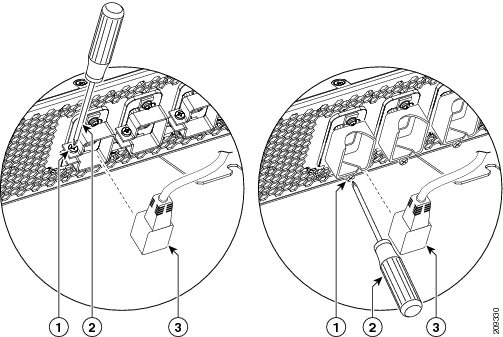
Step 1 To disconnect the PDU output cords from the rear of the modular configuration AC power shelf, use the number 1 Phillips screwdriver to loosen the screw that clamps the cord in place and remove the cord.
1
Screw that secures the cord clamp
3
Cord removed from clamp
2
Screwdriver to loosen screw
Note In the above figure, the cord clamp shown on the left was available until June 2011, and the cord clamp shown on the right is available from June 2011onwards. The location of the screw that secures the cord in the cord clamp is different. Step 2 Use the appropriate tool to remove the four screws—two on each side—attaching the rack mounting brackets on the PDU to the rack vertical mounting brackets. Step 3 Carefully remove the PDU from the rack and place on the workstation.
Installing PDU Kit to Side of Cisco CRS 16-Slot Line Card Chassis
This section describes how to install an AC Delta or AC Wye PDU on the side of the Cisco CRS 16-slot line card chassis. This section contains the following procedures:
Note
Although there are differences between the AC Delta and AC Wye PDU, they are installed in the same manner.One PDU is attached to each side of the Cisco CRS 16-slot line card chassis using a chassis mounting bracket kit (Cisco product number CRS-PDU-BRACKET=). The procedure for installing a PDU kit is the same on both sides of the chassis.
The PDU is shipped with removable 19-inch rack mounting brackets and screws, which are required for conventional mounting in a 19-inch standard rack. The rack mounting brackets must be removed before the PDU is mounted to the chassis mounting bracket.
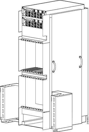
This figure shows the front view of the PDUs installed on the left and right side of the Cisco CRS 16-slot line card chassis.
Note
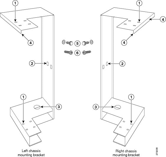
PDU power cords are not shown in above figure.This figure shows the chassis mounting bracket kit (Cisco product number CRS-PDU-BRACKET=) that is used to mount the PDU to the left and right sides of the Cisco CRS 16-slot line card chassis.
1
PDU mounting holes
4
Alignment groove
2
Chassis mounting holes
5
M8 hex head bolt and washer, two per bracket
3
Floor mounting hole
6
Pan head screw, eight per bracket
Prerequisites
Caution
Before you begin this procedure, ensure that all power is disconnected from the Cisco CRS PDU. Remove the PDU input plug(s) from the branch circuit outlet(s).
Before you install the PDU, be aware of the following:
- Consideration should be given to the connection of the equipment to the supply circuit, and to the effect that overloading of the circuits might have on overcurrent protection and supply wiring. Appropriate consideration of equipment nameplate ratings should be used when addressing this concern.
- Particular attention should be given to supply connections other than direct connections to the branch circuit (for example, use of power strips).
Note
Although there are differences between the left and right chassis mounting brackets, the PDUs are installed on the left and right sides of the Cisco CRS 16-slot line card chassis using the same procedures.Required Tools and Equipment
The following tools are required to install the PDU on the Cisco CRS 16-slot line card chassis:
- Number 1 x 6 in. Phillips screwdriver
- M12 6pt. combination wrench
- Torque wrench with M12 6pt. socket and rated accuracy at 40 to 50 in-lb (4.52 to 5.65 N-m)
- PDU
- AC Delta PDU kit (Cisco product number CRS-16-PDU-Delta=), or
- AC Wye PDU kit (Cisco product number CRS-16-PDU-Wye=)
Steps
ProcedureTo install the PDU on the side of the chassis, perform the following steps:
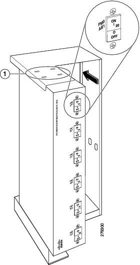
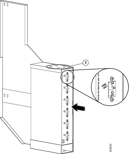
Step 1 Using the number 1 Phillips screwdriver, loosen the four flat head screws that attach each rack mounting bracket to the left and right side of the PDU. Step 2 Remove the rack mounting brackets and screws and set them aside. Step 3 Slide the PDU into the chassis mounting bracket. Align the screw holes on the PDU with the screw holes on the top of the chassis mounting bracket. See the below figure.
Note When installing the PDU in the chassis mounting bracket, ensure that PM0 is positioned on top.
1
PDU mounting holes
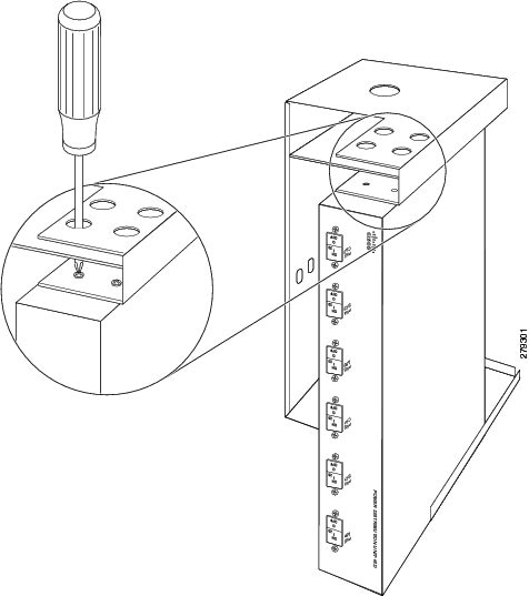
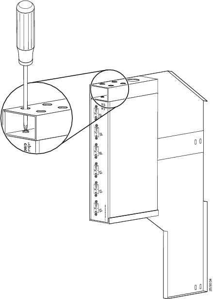
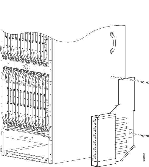
Step 4 Use the number 1 Phillips screwdriver to tighten the four screws that attach the PDU to the top of the chassis mounting bracket. Step 5 Turn the chassis mounting bracket and PDU so that the bottom of the PDU is facing upward. Step 6 Use the number 1 Phillips screwdriver to tighten the four screws that attach the PDU to the bottom of the chassis mounting bracket, as shown in the figure Attaching Bottom of PDU to Left Chassis Mounting Bracket. Step 7 Align the chassis mounting bracket and PDU with the two chassis mounting holes, as shown in the figure Attaching Chassis Mounting Bracket and PDU to Left Side of Chassis .
Note We recommend that the minimum cable bend radius for the PDU input and output power cords is seven times the power cord diameter. Step 8 Use the M12 wrench to tighten the two M8 bolts that attach the chassis mounting bracket and PDU to the chassis, as shown in the figure Attaching Chassis Mounting Bracket and PDU to Left Side of Chassis. Using the torque wrench, tighten the bolts to the recommended install torque of 40 to 50 in-lb (4.52 to 5.65 N-m).
Note We recommend that you bolt the chassis mounting bracket and PDU to the floor using a 1/2-in. diameter bolt for added stability. This bolt is not shipped with the PDU. Step 9 Connect the output cords on the PDU to the rear of the Cisco CRS 16-slot line card chassis modular configuration AC power shelf.
Note Each output cord on the PDU has a label that designates into which socket it should be plugged (PM0, PM1, and so on).
1
Screw that secures the cord clamp
3
Cord to be inserted into clamp
2
Screwdriver tightening screw
Note In yjr above figure, the cord clamp shown on the left was available until June 2011, and the cord clamp shown on the right is available from June 2011onwards. The location of the screw that secures the cord in the cord clamp is different. Step 10 Use the number 1 Phillips screwdriver to tighten the screw that clamps the cord in place. Step 11 Plug the PDU AC input plug into the facility power to energize the Cisco CRS 16-slot line card chassis.
What to Do Next
After the installation of the PDU is complete, you can power up the power modules and the chassis and put the Cisco CRS 16-slot line card chassis router into service. See Cisco CRS Carrier Routing System 16-Slot Line Card Chassis Installation Guide for more information.
Removing PDU Kit from Side of Cisco CRS 16-Slot Line Card Chassis
This section describes how to remove an AC Delta or AC Wye PDU from the Cisco CRS 16-slot line card chassis.
Note
Although there are differences between the AC Delta and AC Wye PDU, they are removed in the same manner.Prerequisites
Caution
Before you begin this procedure, ensure that all power is disconnected from the Cisco CRS PDU. Remove the PDU input plug(s) from the branch circuit outlet(s).
Required Tools and Equipment
The following tools are required to remove the PDU:
- Number 1 x 6 in. Phillips screwdriver
- M12 6 pt. combination wrench.
Steps
Procedure
Step 1 To disconnect the PDU output cords from the rear of the Cisco CRS 16-slot line card chassis modular configuration AC power shelf, use the number 1 Phillips screwdriver to loosen the screw that clamps the cord in place and remove the cord.
1
Screw that secures the cord clamp
3
Cord removed from clamp
2
Screwdriver to loosen screw
Note In the above figure, the cord clamp shown on the left was available until June 2011, and the cord clamp shown on the right is available from June 2011onwards. The location of the screw that secures the cord in the cord clamp is different. Step 2 Remove the bolt that attaches the chassis mounting bracket and PDU to the floor. Step 3 Use the wrench to loosen the two bolts that attach the chassis mounting bracket and PDU to the side of the chassis. Remove bolts.
1
M8 x 1.25 hex mounting bolt (x 2)
Step 4 Place the chassis mounting bracket on the workstation. Step 5 Turn the chassis mounting bracket and PDU so that the bottom of the PDU is facing upward. Step 6 Use the number 1 Phillips screwdriver to remove the four screws that attach the PDU to the bottom of the chassis mounting bracket. Step 7 Turn the chassis mounting bracket and PDU so that the top of the PDU is facing upwards. Step 8 Use the number 1 Phillips screwdriver to remove the four screws that attach the PDU to the top of the chassis mounting bracket. Step 9 Remove the PDU from the chassis mounting bracket.
1
PDU mounting holes
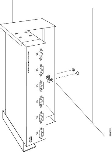
Installing PDU Kit to Side of Cisco CRS Fabric Card Chassis
This section describes how to install an AC Delta or AC Wye PDU on the side of the Cisco CRS fabric card chassis. This section contains the following procedures:
Note
Although there are differences between the AC Delta and AC Wye PDU, they are installed in the same manner.One PDU is attached to each of the Cisco CRS fabric card chassis using a chassis mounting bracket kit (Cisco product number CRS-FCC-PDU-BKT=). The procedure for installing a PDU kit is the same on both sides of the chassis.
The PDU is shipped with removable 19-inch rack mounting brackets and screws, which are required for conventional mounting in a 19-inch standard rack. The rack mounting brackets must be removed before the PDU is mounted to the chassis mounting bracket.
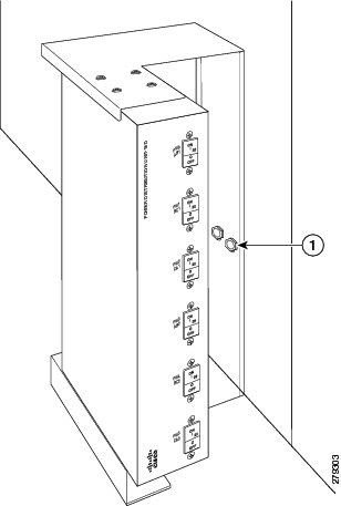
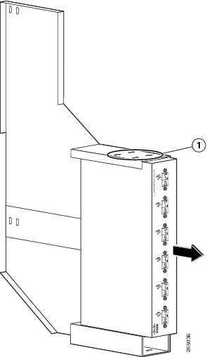
This figure shows the front view of the PDU installed on the right side of the Cisco CRS fabric card chassis.
Note
PDU power cords are not shown in the above figure.This figure shows the chassis mounting bracket kit (Cisco product number CRS-FCC-PDU-BKT=) that is used to mount the PDU to the left and right sides of the Cisco CRS fabric card chassis.
1
PDU mounting holes
4
Alignment groove
2
Chassis mounting holes
5
M8 hex head bolt and integrated washer, four per bracket
3
Floor mounting hole
6
Pan head screw, eight per bracket
Prerequisites
Caution
Before you begin this procedure, ensure that all power is disconnected from the Cisco CRS PDU. Remove the PDU input plug(s) from the branch circuit outlet(s).
Before you install the PDU, be aware of the following:
- Consideration should be given to the connection of the equipment to the supply circuit, and to the effect that overloading of the circuits might have on overcurrent protection and supply wiring. Appropriate consideration of equipment nameplate ratings should be used when addressing this concern.
- Particular attention should be given to supply connections other than direct connections to the branch circuit (for example, use of power strips).
Note
Although there are differences between the left and right chassis mounting brackets, the PDUs are installed on the left and right sides of the Cisco fabric chassis using the same procedures.Required Tools and Equipment
The following tools are required to install the PDU on the Cisco CRS fabric card chassis:
- Number 1 x 6 in. Phillips screwdriver
- M12 6pt. combination wrench
- Torque wrench with M12 6 pt. socket and rated accuracy at 40 to 50 in.-lb (4.52 to 5.65 N-m)
- PDU kit
- AC Delta PDU kit (Cisco product number CRS-FCC-PDU-Delta=), or
- AC Wye PDU kit (Cisco product number CRS-FCC-PDU-Wye=)
Steps
ProcedureTo install the PDU on the side of the chassis, perform the following steps:
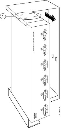
Step 1 Using the number 1 Phillips screwdriver, loosen the four flat head screws that attach each rack mounting bracket to the left and right side of the PDU. Step 2 Remove the rack mounting brackets and screws and set them aside. Step 3 Slide the PDU into the chassis mounting bracket. Align the screw holes on the PDU with the screw holes on the top of the chassis mounting bracket.
Note When installing the PDU in the chassis mounting bracket, ensure that PM0 is positioned on top.
1
PDU mounting holes
Step 4 Use the number 1 Phillips screwdriver to tighten the four screws that attach the PDU to the top of the chassis mounting bracket. Step 5 Turn the chassis mounting bracket and PDU so that the bottom of the PDU is facing upward. Step 6 Use the number 1 Phillips screwdriver to tighten the four screws that attach the PDU to the bottom of the chassis mounting bracket, as shown in the below figure. Step 7 Turn the chassis mounting bracket and PDU so that the top of the PDU is facing upward. Align the chassis mounting bracket and PDU with the four chassis mounting holes, as shown in the below figure.
Note We recommend that the minimum cable bend radius for the PDU input and output power cords is seven times the power cord diameter. Step 8 Use the wrench to tighten the four M8 bolts with integrated washers that attach the chassis mounting bracket and PDU to the chassis. Using the torque wrench, tighten the bolts to the recommended install torque of 40 to 50 in-lb (4.52 to 5.65 N-m). Step 9 Connect the output cords on the PDU to the rear of the Cisco CRS fabric card chassis modular configuration AC power shelf.
Note Each output cord on the PDU has a label that designates into which socket it should be plugged (PM0, PM1, and so on).
1
Screw that secures the cord clamp
3
Cord to be inserted into clamp
2
Screwdriver tightening screw
Note In the above figure, the cord clamp shown on the left was available until June 2011, and the cord clamp shown on the right is available from June 2011onwards. The location of the screw that secures the cord in the cord clamp is different. Step 10 Use the number 1 Phillips screwdriver to tighten the screw that clamps the cord in place. Step 11 Plug the PDU AC input plug into the facility power to energize the Cisco CRS fabric card chassis.
What to Do Next
After the installation of the PDU is complete, you can power up the power modules and the chassis and put the Cisco CRS fabric card chassis router into service. See Cisco CRS Carrier Routing System Fabric Card Chassis Installation Guide for more information.
Removing PDU Kit from Side of Chassis
This section describes how to remove an AC Delta or AC Wye PDU from the Cisco CRS fabric card chassis.
Note
Although there are differences between the AC Delta and AC Wye PDU, they are removed in the same manner.Prerequisites
Caution
Before you begin this procedure, ensure that all power is disconnected from the Cisco CRS PDU. Remove the PDU input plug(s) from the branch circuit outlet(s).
Required Tools and Equipment
The following tools are required to remove the PDU:
- Number 1 x 6 in. Phillips screwdriver
- M12 6 pt. combination wrench.
Steps
Procedure
Step 1 To disconnect the PDU output cords from the rear of the Cisco CRS fabric card chassis modular configuration AC power shelf, use the number 1 Phillips screwdriver to loosen the screw that clamps the cord in place and remove the cord.
1
Screw that secures the cord clamp
3
Cord removed from clamp
2
Screwdriver to loosen screw
Note In the above figure, the cord clamp shown on the left was available until June 2011, and the cord clamp shown on the right is available from June 2011onwards. The location of the screw that secures the cord in the cord clamp is different. Step 2 Use the wrench to loosen the four bolts that attach the chassis mounting bracket and PDU to the side of the chassis. Remove bolts. Step 3 Place the chassis mounting bracket on the workstation. Step 4 Turn the chassis mounting bracket and PDU so that the bottom of the PDU is facing upward. Step 5 Use the number 1 Phillips screwdriver to remove the four screws that attach the PDU to the bottom of the chassis mounting bracket. Step 6 Turn the chassis mounting bracket and PDU so that the top of the PDU is facing upwards. Step 7 Use the number 1 Phillips screwdriver to remove the four screws that attach the PDU to the top of the chassis mounting bracket. Step 8 Remove the PDU from the chassis mounting bracket.
1
PDU mounting holes
Specifications
This section describes the specifications for the Cisco CRS Power Distribution Unit.
The requirements for the Cisco CRS PDU are:
- Cisco CRS PDU is field retrofittable with Cisco CRS Carrier Router System installation base.
- Cisco CRS PDU supports Cisco CRS 8-slot line card chassis, Cisco CRS 16-slot line card chassis, or Cisco CRS fabric card chassis to operate with partial and full power modular capacity.
- Cisco CRS PDU supports 2N redundant mode and allows replacement of either of the two redundant PDUs without impacting system traffic.
This table lists the specifications for both types of Cisco CRS PDU available for use with the Cisco CRS 8-slot line card chassis, PDU-321-3-Delta and PDU-321-3-Wye.
Table 1 PDU-321-3-Delta and PDU-321-3-Wye Specifications Description
Value
Height
3.5 in. (8.9 cm)
Width
8.75 in. (22.2 cm), single PDU17.5 in. (44.5 cm), including rack tray19.3 in. (49.0 cm), including rack mounting brackets
Depth
7.0 in. (17.8 cm)
Weight
43 lb. (19 kg), PDU-321-3-Delta, including tray31 lb. (14 kg), PDU-321-3-Wye, including tray
Input cord length
177 in. (450 cm)
Output cord length
138 in. (350 cm)
PDU-321-3-Delta
3-Phase AC Delta
Input
200 to 240 VAC, 50 to 60 Hz, 27.7 ATolerance: +/–10% (180 to 264) VAC, 50 to 60 Hz, 27.7 A
Rated Current
27.7 A
Recommended AC Service
40 A minimum, 60 A maximum dedicated branch circuit
Output
200 to 240 VAC, 50 to 60 Hz, 16 ATolerance: +/–10%(180 to 264) VAC, 50 to 60 Hz, 16 A
Input Connection (per single PDU)
One IEC 60309, 250V/60A, 3W+PE (3 wire + protective earthing)1
Output Connection (per single PDU)
Three IEC-320-C21 Connector 90 degree female cords
PDU-321-3-Wye
3-Phase AC Wye
Input
200 to 240 (L-N)/346 to 415 (L-L) VAC, 50 to 60 Hz, 16 ATolerance: +/–10% (180 to 264)(L-N)/(311 to 456)(L-L) VAC, 50 to 60 Hz, 16 A
Rated Current
16 A
Recommended AC Service
16 A dedicated branch circuit
Output
200 to 240 VAC, 50 to 60 Hz, 16 ATolerance: +/–10%(180 to 264) VAC, 50 to 60 Hz, 16 A
Input Connection (per single PDU)
One IEC 60309, 415V/16A, 3W+N+PE (3 wire + neutral + protective earthing)1
Output Connection Type (per single PDU)
Three IEC-320-C21 Connector 90 degree female cords
1 Protective earthing conductor (ground wire).This table lists the specifications for both types of Cisco CRS PDU available for use with the Cisco CRS 16-slot line card chassis and Cisco CRS fabric card chassis, PDU-321-6-Delta and PDU-321-6-Wye.
Table 2 PDU-321-6-Delta and PDU-321-6-Wye Specifications Description
Value
Height
2.0 in. (5.1 cm)
Width
17.5 in. (44.5 cm) single PDU19.3 in. (49.0 cm) including rack mounting brackets
Depth
6.0 in (15.2 cm)
Weight
77 lb (35 kg) Delta PDU kit for Cisco CRS 16-Slot LCC
51 lb (23 kg) Wye PDU kit for Cisco CRS 16-Slot LCC
86 lb (39 kg) Delta PDU kit for Cisco CRS FCC
60 lb (27 kg) Wye PDU kit for Cisco CRS FCC
Each PDU kit includes two individual PDUs and two chassis-mounting brackets.
Input cord length
177 in. (450 cm)
Output cord length
138 in. (350 cm)
PDU-321-6-Delta
3-Phase AC Delta
Input
200 to 240 VAC, 50 to 60 Hz, 27.7 ATolerance: +/–10% (180 to 264) VAC, 50 to 60 Hz, 27.7 A
Rated Current
Two 27.7 A
Recommended AC Service
Two 40 A minimum, two 60 A maximum dedicated branch circuits
Output
200 to 240 VAC, 50 to 60 Hz, 16 ATolerance: +/–10%(180 to 264) VAC, 50 to 60 Hz, 16 A
Input Connection (per single PDU)
Two IEC 60309, 250V/60A, 3W+PE (3 wire + protective earthing) 1
Output Connection (per single PDU)
Six IEC-320-C21 Connector 90 degree female cords
PDU-321-6-Wye
3-Phase AC Wye
Input
200 to 240 (L-N)/346 to 415 (L-L) VAC, 50 to 60 Hz, 32ATolerance: +/–10% (180 to 264)(L-N)/(311 to 456)(L-L) VAC, 50 to 60 Hz, 32A
Rated Current
32 A
Recommended AC Service
32 A dedicated branch circuit
Output
200 to 240 VAC, 50 to 60 Hz, 16 ATolerance: +/–10%(180 to 264) VAC, 50 to 60 Hz, 16 A
Input Connection (per single PDU)
One IEC 60309, 415V/32A, 3W+N+PE (3 wire + neutral + protective earthing)2
Output Connection (per single PDU)
Six IEC-320-C21 Connector 90 degree female cords
2 Protective earthing conductor (ground wire).This table lists the environmental specifications for the Cisco CRS PDU.
Table 3 Cisco CRS PDU Environmental Specifications Description
Value
Temperature
Operating, nominal
41 to 104 o F (5 to 40 o C)
Nonoperating
40 to 158 o F (-40 to 70 o C)
Humidity
Operating
5 to 85% noncondensing
Nonoperating
5 to 90% noncondensing, short-term
Altitude
197 to 5906 ft. (-60 to 1800 m) at 122 o F (50 o C), short-termUp to 13,123 ft. (4000 m) at 104 o F (40 o C) or below
Copyright © 2016, Cisco Systems, Inc. All rights reserved.


 Feedback
Contact Cisco
- Open a Support Case

- (Requires a Cisco Service Contract)