Ethernet over MPLS
Ethernet-over-MPLS (EoMPLS) provides a tunneling mechanism for Ethernet traffic through an MPLS-enabled Layer 3 core, and encapsulates Ethernet protocol data units (PDUs) inside MPLS packets (using label stacking) to forward them across the MPLS network.
The following table summarizes the load balancing behavior for VPLS and VPWS Ethernet bundle attachment circuits from Release 6.3.3 onwards. In the default configuration mode, the parameters used for load balancing through LAG Hashing is provided for disposition traffic flowing from MPLS network, for example, pseudowires to Ethernet attachment circuits.
 Note |
VLAN tags (Service and Customer) are not considered for load balancing. |
|
Ethernet Frame Type |
Parameters for Load Balancing Through LAG Hashing |
|---|---|
|
Ethernet Frame with non-IP payload |
|
|
Ethernet Frame with IP payload |
|
|
Ethernet Frame with IP payload and TCP/UDP payload |
|
The following sections describe the different modes of implementing EoMPLS.
Ethernet Port Mode
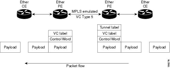
In Ethernet port mode, both ends of a pseudowire are connected to Ethernet ports. In this mode, the port is tunneled over the pseudowire or, using local switching (also known as an attachment circuit-to-attachment circuit cross-connect) switches packets or frames from one attachment circuit (AC) to another AC attached to the same PE node.
This figure shows a sample ethernet port mode packet flow:
VLAN Mode
In VLAN mode, each VLAN on a customer-end to provider-end link can be configured as a separate L2VPN connection using virtual connection (VC) type 4 or VC type 5. VC type 5 is the default mode.
As illustrated in the following figure, the Ethernet PE associates an internal VLAN-tag to the Ethernet port for switching the traffic internally from the ingress port to the pseudowire; however, before moving traffic into the pseudowire, it removes the internal VLAN tag.
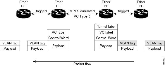
At the egress VLAN PE, the PE associates a VLAN tag to the frames coming off of the pseudowire and after switching the traffic internally, it sends out the traffic on an Ethernet trunk port.
 Note |
Because the port is in trunk mode, the VLAN PE doesn't remove the VLAN tag and forwards the frames through the port with the added tag. |
Inter-AS Mode
Inter-AS is a peer-to-peer type model that allows extension of VPNs through multiple provider or multi-domain networks. This lets service providers peer up with one another to offer end-to-end VPN connectivity over extended geographical locations.
EoMPLS support can assume a single AS topology where the pseudowire connecting the PE routers at the two ends of the point-to-point EoMPLS cross-connects resides in the same autonomous system; or multiple AS topologies in which PE routers can reside on two different ASs using iBGP and eBGP peering.
The following figure illustrates MPLS over Inter-AS with a basic double AS topology with iBGP/LDP in each AS.

QinQ Mode
QinQ is an extension of 802.1Q for specifying multiple 802.1Q tags (IEEE 802.1QinQ VLAN Tag stacking). Layer 3 VPN service termination and L2VPN service transport are enabled over QinQ sub-interfaces.
Cisco NCS 560 Series Routers implement the Layer 2 tunneling or Layer 3 forwarding depending on the sub-interface configuration at provider edge routers. This function only supports up to two QinQ tags on the router:
-
Layer 2 QinQ VLANs in L2VPN attachment circuit: QinQ L2VPN attachment circuits are configured under the Layer 2 transport sub-interfaces for point-to-point EoMPLS based cross-connects using both virtual circuit type 4 and type 5 pseudowires and point-to-point local-switching-based cross-connects including full inter-working support of QinQ with 802.1q VLANs and port mode.
-
Layer 3 QinQ VLANs: Used as a Layer 3 termination point, both VLANs are removed at the ingress provider edge and added back at the remote provider edge as the frame is forwarded.
Layer 3 services over QinQ include:
-
IPv4 unicast and multicast
-
IPv6 unicast and multicast
-
MPLS
-
Connectionless Network Service (CLNS) for use by Intermediate System-to-Intermediate System (IS-IS) Protocol
In QinQ mode, each CE VLAN is carried into an SP VLAN. QinQ mode should use VC type 5, but VC type 4 is also supported. On each Ethernet PE, you must configure both the inner (CE VLAN) and outer (SP VLAN).
The following figure illustrates QinQ using VC type 4.

 Note |
EoMPLS does not support pseudowire stitching or multi segments. |




 Feedback