The documentation set for this product strives to use bias-free language. For the purposes of this documentation set, bias-free is defined as language that does not imply discrimination based on age, disability, gender, racial identity, ethnic identity, sexual orientation, socioeconomic status, and intersectionality. Exceptions may be present in the documentation due to language that is hardcoded in the user interfaces of the product software, language used based on RFP documentation, or language that is used by a referenced third-party product. Learn more about how Cisco is using Inclusive Language.
The Cisco Container Platform tenant base VM contains the container image and the files that are necessary to create the tenant Kubernetes clusters that
are used for configuring monitoring, logging, container network interfaces (CNI), and persistent volumes.
The Cisco Container Platform Control Plane is set up using an installer UI. After the installer VM is switched on, the URL of the installer appears on
the vCenter Web console.
Log in to the VMware vSphere Web Client as an administrator.
Step 2
In the Navigation pane, right-click the cluster on which you want to deploy Cisco Container Platform, and then choose Deploy OVF Template.
The Deploy OVF Template wizard appears.
Step 3
In the Select template screen, perform these steps:
Click the URL radio button, and enter the URL of the Installer OVA.
Alternatively, click the Local file radio button, and browse to the location where the Installer OVA is saved on your computer.
Note
The format of the Installer OVA filename is as follows:
kcp-vm-x.y.z.ova
Where x, y, z corresponds to the major, minor, and patch release of Cisco Container Platform.
Click Next.
Step 4
In the Select name and location screen, perform these steps:
In the Name field, enter a name for the installer VM.
In the Browse tab, choose the data center where you want to deploy Cisco Container Platform.
Click Next.
Step 5
In the Select a resource screen, choose the cluster where you want to run the installer VM, and then click Next.
Step 6
In the Review details screen, verify the template details, and then click Next.
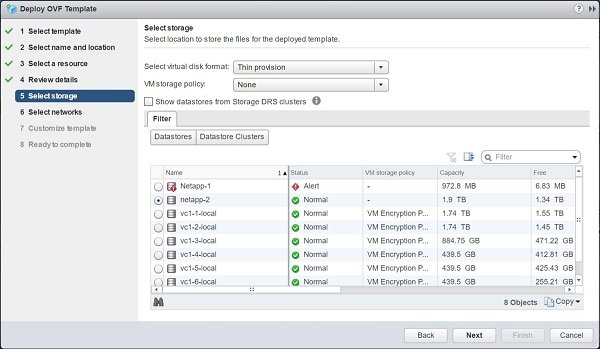
Step 7
In the Select storage screen, perform these steps:
From the Select virtual disk format drop-down list, choose Thin Provision to allocate storage on demand.
In the Filters tab, choose a destination datastore to store the installer VM.
Click Next.
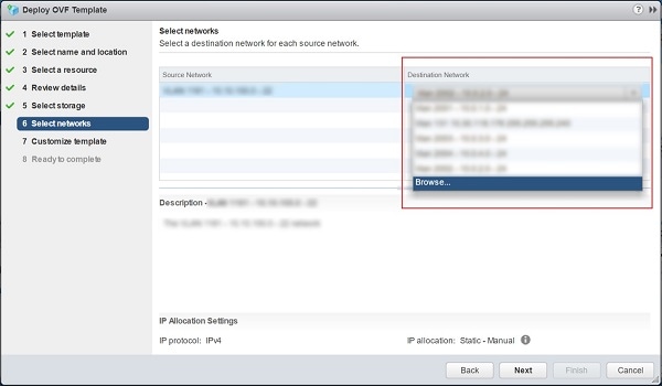
Step 8
In the Select networks screen, perform these steps:
From the Destination Network column, choose a network for each source network that is available in the installer VM.
Note
The selected network must have access to vCenter and the tenant VM networks.
Click Next.
The Customize template screen appears.
Figure 3. Customize Template Screen
Step 9
In the Customize template screen, enter the following optional parameters to customize the deployment properties:
Expand CCP, in the SSH public key for installer node access field, enter an ssh public key.
You can use this key to ssh to the installer VM.
Note
Ensure that you enter the public key in a single line.
If you do not have an SSH key pair, you can generate it using the ssh-keygen command.
Ensure that you use the Ed25519 or ECDSA format for the public key.
Note: As RSA and DSA are less secure formats, Cisco prevents the use of these formats.
Expand Advance and enter the optional fields as necessary.
In the CIDR for Kubernetes pod network field, 192.168.0.0/24 is displayed as the default pod network CIDR of the Kubernetes cluster for the installer. If the CIDR IP addresses conflict
with the tenant cluster VM network or the vCenter network, you need to set a different value for the CIDR.
This CIDR is the single large CIDR from which smaller CIDRs are automatically allocated to each node for allocating IP addresses
to the pods in the Kubernetes cluster. For more information, refer to https://kubernetes.io/docs/concepts/cluster-administration/networking/.
Click Next.
Step 10
In the Ready to complete screen, verify the installer VM deployment settings, and then click Finish.
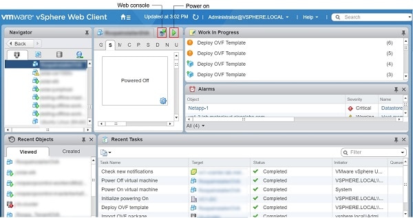
Step 11
Click the Power on button to switch on the VM.
Figure 4. Switching on Installer VM
Once the installer VM is switched on, the installer UI takes a few minutes to become ready. You can view the status of the
Installer UI using the Web console of vCenter. When the installer UI is ready, you can access it using the URL from the Web console.
You can use the ssh private key to access the Installer, control plane VMs, or the tenant cluster VMs. However, logging into
these VMs using a username and password is not supported.
Caution
After deploying Cisco Container Platform, do not change the location of the Control Plane VMs by modifying the datacenter or folder location in vSphere. Changing these settings will adversely impact the management of clusters.
Deploying Cisco Container Platform
The Cisco Container Platform Control Plane is set up using an installer UI. After the installer VM is switched on, the URL of the installer appears on
the vCenter Web console.
Procedure
Step 1
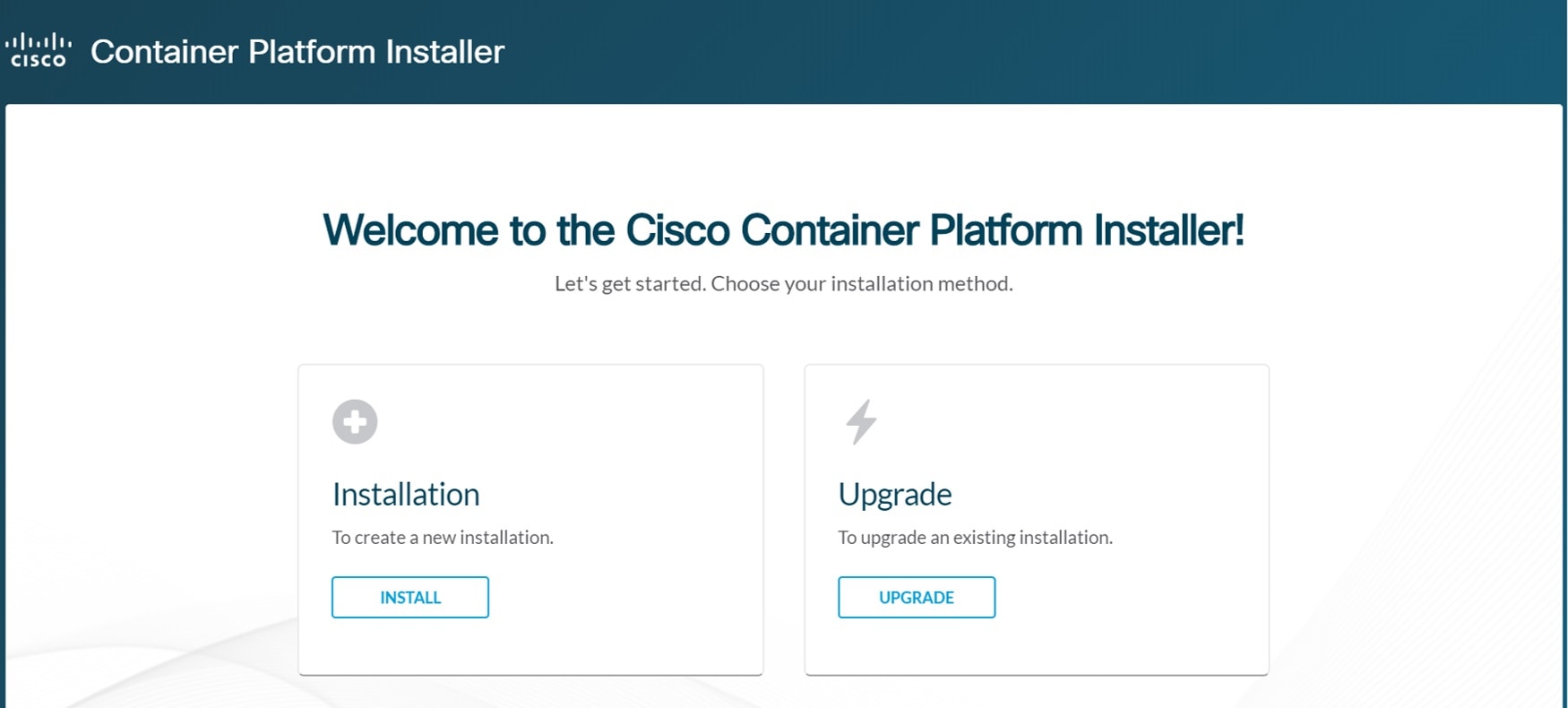
Obtain the URL from the vCenter Web console and use a browser to open the installer UI.
The Welcome screen appears.
Figure 5. Welcome Screen
Step 2
Click Install.
The Connect your Cloud screen appears.
Figure 6. Connect your Cloud Screen
Step 3
In the Connect your Cloud screen, enter the following information:
In the VCENTER HOSTNAME OR IP ADDRESS field, enter the IP address of the vCenter instance that you want to use.
In the PORT field, enter the port number that your vCenter server uses.
Note
The default port for vCenter is 443.
In the VCENTER USERNAME field, enter the username of the user with administrator access to the vCenter instance.
In the VCENTER PASSPHRASE field, enter the passphrase of the vCenter user.
Click CONNECT.
The Placement Properties screen appears.
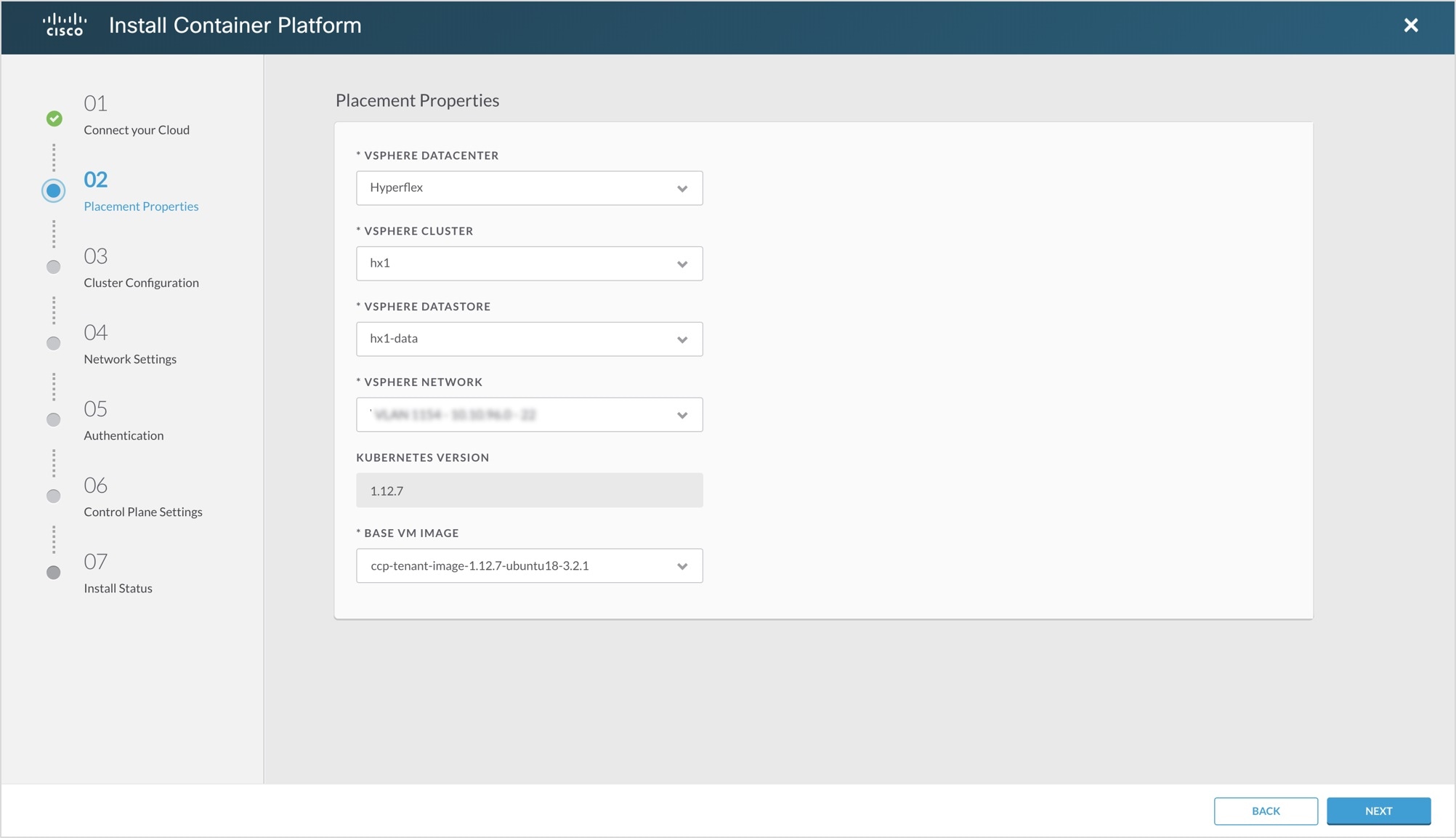
Figure 7. Placement Properties Screen
Step 4
In the Placement Properties screen, enter the following information:
From the VSPHERE DATACENTER drop-down list, choose the datacenter.
From the VSPHERE CLUSTER drop-down list, choose the cluster.
From the VSPHERE DATASTORE drop-down list, choose the datastore.
Caution
Do not use a datastore located in a nested folder or a Storage DRS (SDRS).
From the VSPHERE NETWORK drop-down list, choose the network.
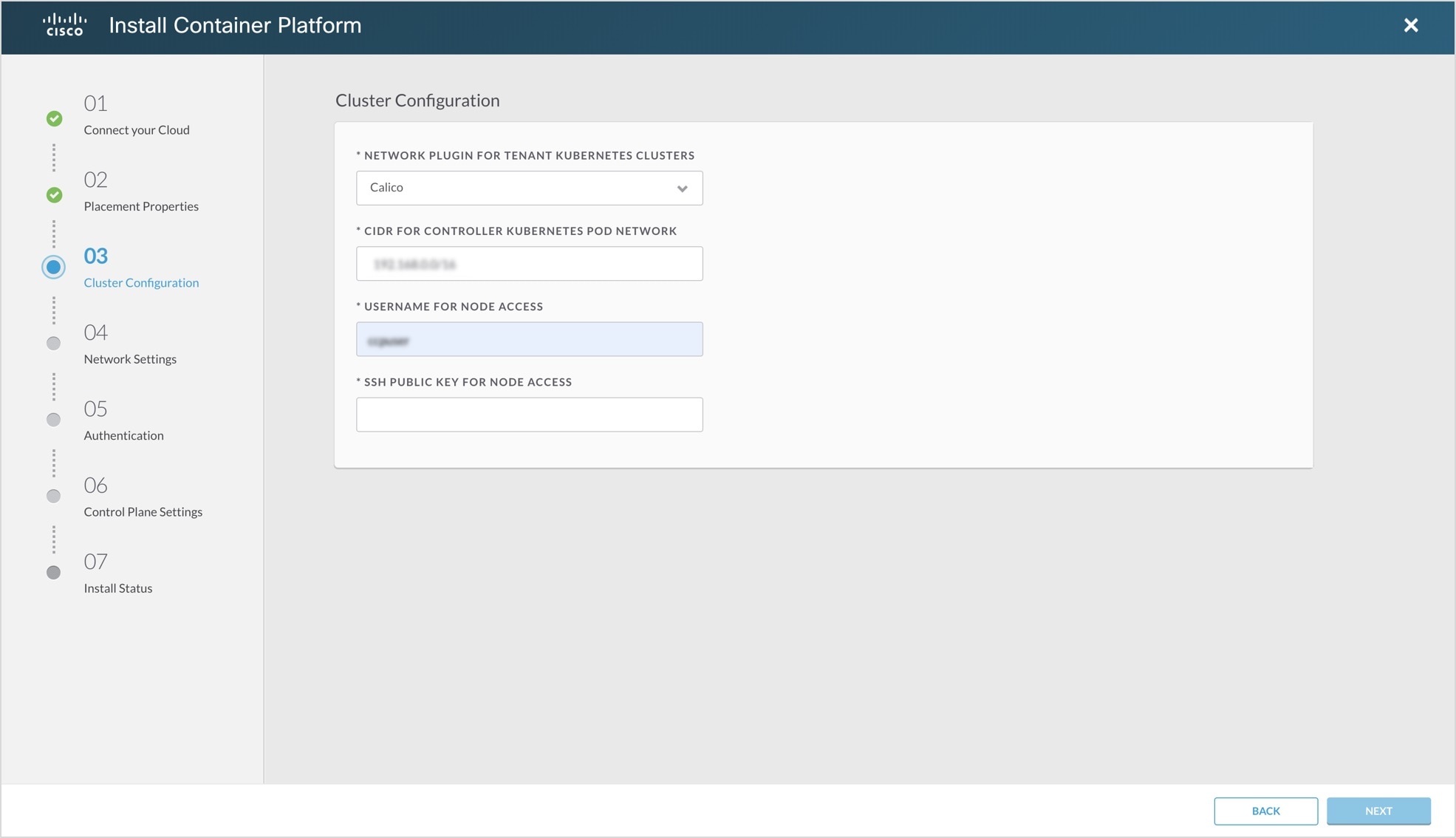
In the CIDR FOR CONTROLLER KUBERNETES POD NETWORK field, 192.168.0.0/16 is displayed as the default pod network CIDR of the Kubernetes cluster for the installer. If the CIDR IP addresses conflict
with the tenant cluster VM network or the vCenter network, you need to set a different value for the CIDR.
Note
This CIDR is the single large CIDR from which smaller CIDRs are automatically allocated to each node for allocating IP addresses
to the pods in the Kubernetes cluster. For more information, refer to https://kubernetes.io/docs/setup/scratch/#network-connectivity.
In the USERNAME FOR NODE ACCESS field, enter the username of the user who can ssh into the Cisco Container Platform Control Plane nodes.
In the SSH PUBLIC KEY FOR NODE ACCESS field, enter an ssh public key.
You can use this key to ssh to the Control Plane nodes.
Note:
Ensure that you enter the public key in a single line.
If you do not have an SSH key pair, you can generate it using the ssh-keygen command.
Ensure that you use the Ed25519 or ECDSA format for the public key.
Note: As RSA and DSA are less secure formats, Cisco prevents the use of these formats.
Click NEXT.
The Network Settings screen appears.
Figure 9. Network Settings Screen
Step 6
In the Network Settings screen, enter the following information:
Note
These network settings will be used to configure the Cisco Container Platform web interface.
In the NETWORK NAME field, enter the name of the network that you want to use.
In the SUBNET CIDR field, enter a CIDR for your subnet.
In the GATEWAY IP field, enter the gateway IP address that you want to use.
Under NAMESERVER, enter the IP address of the necessary DNS nameserver.
You can click +NAMESERVER to enter IP addresses of additional nameservers.
Under POOLS, enter a range for the VIP network pool by specifying the First IP and Last IP that are within the Subnet CIDR specified above. The VIP network pool range enables us to prevent provisioning of tenant
clusters with IP address ranges from overlapping subnets.
The IP address for the Control Plane is also allocated from this network pool range.You can click +POOL to enter multiple pools in the subnet.
Note
You must ensure that these IP addresses are not part of a DHCP pool.
Click SAVE.
The Authentication screen appears.
Figure 10. Authentication Screen
Step 7
In the Authentication screen, click the Enable button next to the type of authentication that you want to configure.
Caution
Use of local authentication is not recommended and is considered less secure for production data.
If you have enabled Active Directory, specify the following information in the Active Directory screen:
Use the toggle button to enable or disable validation of Active Directory settings.
In the SERVER IP ADDRESS field, enter the IP address of the AD server.
In the PORT field, enter the port number for the AD server.
To establish a secure connection using SSL/TLS, enable STARTTLS.
To ensure security of your data, disable SKIP CERTIFICATE VERIFICATION.
Caution
If you enable SKIP CERTIFICATE VERIFICATION, TLS will accept any certificate presented by the AD server. In this mode, TLS is susceptible to data loss.
In the BASE DN field, enter the LDAP query to select the AD group that contains the users who must be granted the User role.
In the SERVICE ACCOUNT DN field, enter the service account domain name that is used for accessing the LDAP server.
In the SERVICE ACCOUNT PASSPHRASE field, enter the passphrase of the AD account.
Click SAVE.
If you have enabled Local (not recommended), specify the following information in the LOCAL AUTHENTICATION screen:
In the LOCAL ADMIN USERNAME field, enter the admin username.
In the LOCAL ADMIN PASSPHRASE field, enter a passphrase.
In the CONFIRM LOCAL ADMIN PASSPHRASE re-enter the admin passphrase.
Click SAVE.
The Control Plane Settings screen appears.
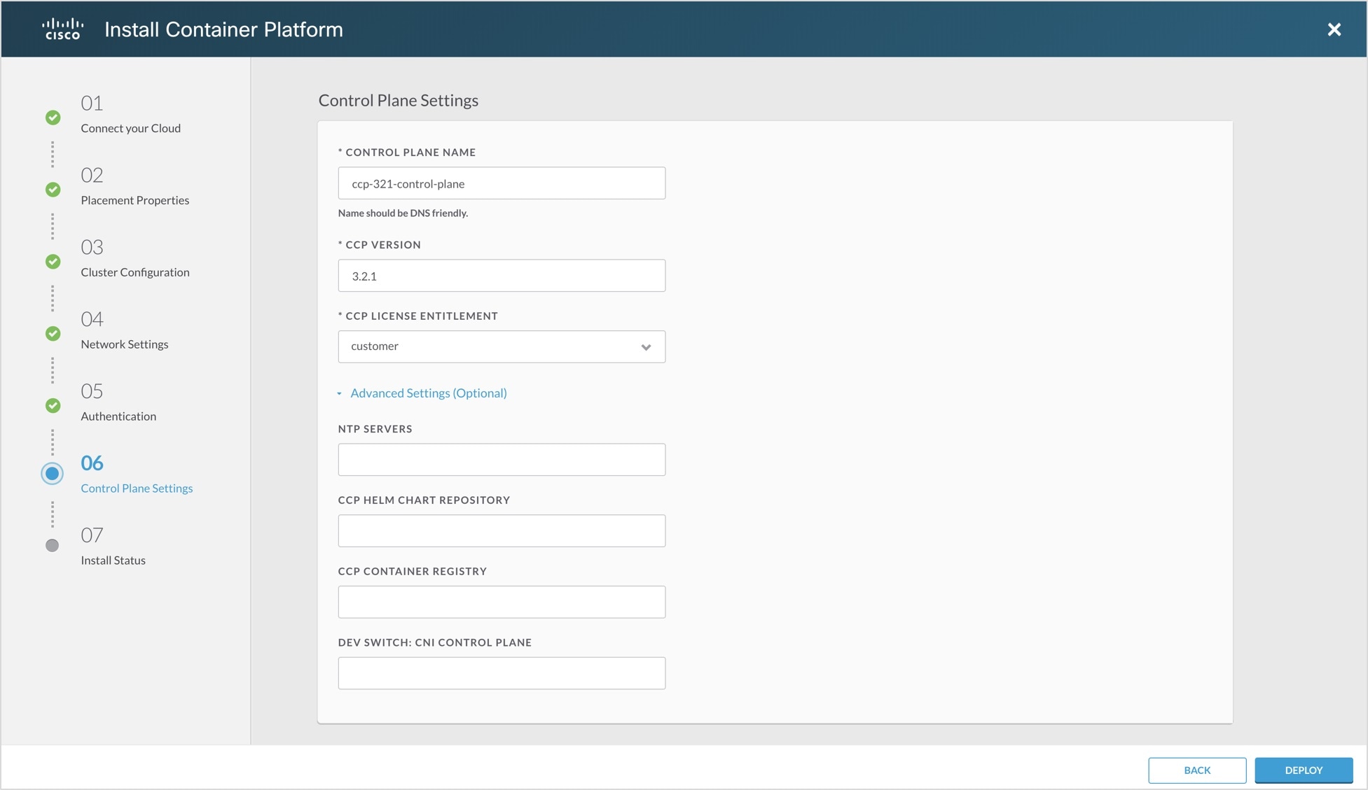
Figure 11. Control Plane Settings Screen
Step 8
In the Control Plane Settings screen, enter the following information:
In the CONTROL PLANE NAME field, enter the name of the Cisco Container Platform cluster.
Note
The cluster name must start with an alphanumeric character (a-z, A-Z, 0-9). It can contain a combination of hyphen (-) symbols
and alphanumeric characters (a-z, A-Z, 0-9). The maximum length of the cluster name is 46 characters.
Deployment of the installer VM fails if another Control Plane cluster with the same name already exists on the same datastore.
You must ensure that you specify a unique name for the Control Plane cluster.
In the CCP VERSION field, enter the version of the Cisco Container Platform cluster.
From the CCP LICENSE ENTITLEMENT drop-down list, choose an entitlement option that indicates the type of Smart Licensing that you want to use.
Note
The Partner option will only be used in conjunction with a Not for Retail (NFR) or Trial license.
Expand Advanced Settings, in the NTP SERVERS field, enter the list of any NTP servers in your environment.
This field is optional.
Click DEPLOY and then monitor the installation progress through the vCenter Web console.
Caution
After deploying Cisco Container Platform, do not change the location of the Control Plane VMs by modifying the datacenter
or folder location in vSphere. Changing these settings will adversely impact the management of clusters.


 Feedback