Cisco Transport Planner DWDM Operations Guide, Software Release 11.x
Bias-Free Language
The documentation set for this product strives to use bias-free language. For the purposes of this documentation set, bias-free is defined as language that does not imply discrimination based on age, disability, gender, racial identity, ethnic identity, sexual orientation, socioeconomic status, and intersectionality. Exceptions may be present in the documentation due to language that is hardcoded in the user interfaces of the product software, language used based on RFP documentation, or language that is used by a referenced third-party product. Learn more about how Cisco is using Inclusive Language.
CTP allows you to edit the a project either before or after network
analysis. Error messages that occur during network analysis often cannot be
resolved until you edit one or more network components. To complete the
procedures in this section, you must have a project open and the network(s)
loaded. See the
Opening a Project and
the
Loading and Unloading Networks.
Editing Project
Parameters
Use the following
procedure to edit project parameters:
Procedure
Step 1
Click
Project in the
Project
Explorer pane.
Step 2
In the
Properties pane, complete the following tasks as
needed:
Customer—Enter the name of the customer (128-character
maximum) requiring this network design.
Created by—Enter the user name (128-character maximum).
Units—Displays the span measurement unit: Km (kilometers) or
Miles.
Price List—Choose the price database from the drop-down list.
Layout—Displays ANSI (the North American standard) or ETSI
(the international standard) to indicate the platform type. ANSI networks do
not allow you to define SDH (ETSI) service demands. ETSI networks do not allow
you to define SONET (ANSI) service demands.
Editing Network
Parameters
Use the following
procedure to edit network parameters:
Procedure
Step 1
Click a network
in the
Project
Explorer pane or Mgmt Tree.
Step 2
In the
Properties pane, complete the following tasks as
needed:
Name—Enter
the network name (128-character maximum).
Position—Enter the object location in pixels.
Created
by—Enter the user name (128-character maximum).
Status—Displays the state of the network (Design, Design-Analyzed, Install, and
so on).
Measurement
Units—Choose Km or Miles from the drop-down list. Any change made to the
measurement unit at the network level will change the measurement unit of all
the ducts within that network. For additional information on changing the
measurement units of an individual duct, see
Editing Fiber Span, Pair, and Fiber Parameters.
Node
Split—Check this check box to enable Split ROADM feature.
Note
To
split or unsplit nodes in the network level, right-click on the network and
choose the appropriate options.
Enable
Layout Movement Optimization Feature—Check this check box to enable the layout
movement optimization feature.
Encryption Always On—Check this check box to ensure that encryption is always enabled. This feature is supported only on
a combination of MR-MXP with 200G-CK-LC card or NCS2K-400G-XP-LC card.
When this check box is checked and the Encryption is selected as Yes in the Demand Editor, the NCS2K-MR-MXP-K9 PID is used
instead of the NCS2K-MR-MXP-LIC PID.
When this check box is unchecked and the Encryption is selected as Yes in the Demand Editor for 100GE demands, CTP uses the
L-NCS2K-MRE100GK9 PID along with the 200G-CK-LC card and MR-MXP PIDs.
When this check box is unchecked and the Encryption value is selected as Yes in the Demand Editor for 10GE or 40GE demands,
CTP uses the L-NCS2K-MRELRGK9 PID along with the 200G-CK-LC card and MR-MXP PIDs.
When this check box is checked or unchecked, no new PID is added for 400G-XP-LC alongwith 400G-XP-LC PIDs.
Use
Bundles—Check this check box to use the Multishelf Management Integrated Kit
bundle when generating the BoM instead of the single items.
Use Spare
Parts—Check this check box to determine the spare parts required by the
network. If the network is in the Upgrade state, the parts required to support
the implemented services and the newly added present services are included. To
generate a spare parts report, you must associate the sites in a network with a
maintenance center before network analysis.
Use Global
Discount—Check this check box to use the global discount for the entire
network. The global discount is applied to all components in the BoM.
Global
Discount—Enter a new global discount in the form of a percentage.
Use Client
Payg—Check this check box to include license for client cards. This option is
applicable to AR-MXP, AR-XP, 100G-LC-C, 100G-CK-LC-C, and 10X10G-LC cards. This
check box is checked by default.
Enable
NCS—Check this check box to enable NCS to use the new NCS PIDs instead of the
ONS 15454 M6, M2 and M12 PIDs.
Connection
Verification—Check this check box to enable the connection verification feature
on the site. When you enable this feature on the network, it is automatically
enabled on the associated sites of the network. The SMR-20 FS CV cards provide
the connection verification feature along with the passive modules MF-DEG-5-CV,
MF-UPG-4-CV, and MF-M16LC-CV. For more details, see
Connection Verification.
Service
Level—Choose the service level (contract) identifier from the drop-down list.
Service
Length—Choose the maintenance service level length (in years) from the
drop-down list.
Include
SW Licenses—Check this check box to include software licenses in the BoM.
Include
Paper Documentation—Check this check box to include paper documentation in the
BoM.
Include
CD Documentation—Check this check box to include CD documentation in the BoM.
Hide
Bom/price discount—Check this check box to hide the global discount in the Unit
Price column of the BoM.
WSON
PID—Check this check box to display the WSON PIDs in the BoM report.
Dimension—Enter the network size in pixels.
Background color—Click to choose a color for the network background.
Background image—Displays the JPEG or GIF filename used as a background, if
any. To choose a JPEG or GIF file as a background graphic for the network,
click the down arrow and navigate to the desired directory.
Editing Site
Parameters
Editing the site
parameters allows you to make changes to the current site configuration. A site
folder in the Project Explorer pane displays the interface node information.
Each site contains an NE folder in which network elements (NEs) are placed. The
NEs are created after the network analysis.
The following
configurations result in more than one NE creation:
Individual shelf with OIC
site functionality: One NE for each side.
Individual shelf: One NE for
each shelf.
Multishelf with line card:
One NE and one NE for each line card shelf.
Modifications in
the site structure, functionality, and type also modify the number of NEs
created.
A site folder for
an analyzed network design also contains the following items, many of which you
can edit:
A and B—For a Line or Line+
site, two interface nodes appear in the Project Explorer pane under the Site
folder, labeled A and B. For a Terminal or Terminal+ site, only one interface
node (A) appears.
A(w) and A(p)—For a PSM
Terminal Optical Path site or a PSM Terminal Multiple Section site, two
interface sides appear in the Project Explorer pane under the Site folder,
labeled A(w) and A(p). A(w) represents the working path and A(p) represents the
protection path. For a PSM Terminal Optical Path site, the following options
are available under the supported bands for the two interfaces.
For A(w): Amplifiers,
add/drop, and DWDM protection
For A(p):
DWDM protection
For a PSM Terminal Multiple
Section site, the following options are available under the supported bands for
the two interfaces.
For A(w): Amplifiers,
add/drop, and DWDM protection
For A(p): Amplifiers and
DWDM protection
C-Band or L-Band—Displays
the supported band for the sides.
Amplifiers—Lists the
amplifiers and all related cards for each band and for each side.
Add/Drop—Displays all of the
add/drop and related cards for the band and side.
Site Type Parameters—When
selected, shows the site functionality and type in the Properties pane.
Band Parameters—When
selected, shows the output power in the Properties pane.
Client—Lists the client
cards.
CTP allows you to
create property templates to design a set of property configurations for a
site. When you have a network that has similar sites, you can use these
property templates to quickly and accurately set up common properties. For more
information, see
Property Template.
Use the following
procedure to edit site parameters. To delete a site, see
Deleting Sites.
Procedure
Step 1
In the
Project
Explorer pane, right-click the network folder and choose
Expand from the shortcut menu.
Step 2
Click the
desired Site folder. The site parameters appear in the
Properties pane.
Step 3
Complete the
following tasks to modify the site parameters in the
Properties pane, as needed:
Name—Enter the site name.
Position—Enter the site pixel position; for example, an entry of 0,0 positions
the Site icon in the upper-left corner of the NtView Name tab.
MTTR
(hours)—Enter the mean time to repair (MTTR) for all sites in the network. This
value applies to every site in the network. If you change the MTTR value after
creating sites, the new value will only apply to sites you create after the
change.
Maintenance Center—Choose the name of the maintenance center from the drop-down
list. To create a maintenance center, see the “Creating a Maintenance Center”
section.
IP
Address—Enter the IP address of the node.
Shelf
Management—Choose one of the shelf configuration types from the drop-down list:
Auto—Sets the default option of the Multi Shelf Switch for all the nodes with
more than one shelf. For M6/M15 chassis, the default option is Multi Shelf
Integrated Switch.
Multi
Shelf Integrated Switch—All the MSTP optical cards (OADMs and amplifiers)
reside in different shelves connected by a LAN. The LAN is implemented with
switches connected to the MSTP shelves. These switches are used to connect to
the external chassis. For this option, Multi-Shelf Integrated Switch Cards
(MS-ISC) are used to support the multishelf configuration. M15 uses RJ 45 and
optical ports to connect to an external chassis.
Multi
Shelf External Switch—All the MSTP optical cards (OADMs and amplifiers) reside
in different shelves connected by a LAN. The LAN is implemented with switches
external to the MSTP shelves (Cisco Catalyst 2950). For this option, two
external Ethernet switch units (Cisco Catalyst 2950 and Cisco Catalyst 3650)
are used to support the multishelf configuration. The Cisco Catalyst 2950
supports 12 subtending shelves and Cisco Catalyst 3650 supports 24 subtending
shelves. CTP supports a maximum of 50 shelves, including the node controller
shelf, in a multishelf configuration when the TNC, TNCE, TSC, TSCE, TNCS,
TNCS-O, or TCC3 card is used as the node controller. CTP supports a maximum of
5 shelves, including the node controller shelf, in a multishelf configuration
when TCC2P card is used as the node controller.
Note
In
Release 10.6.1, the TCC2P card can be used only on a standalone Network Element
(NE) or as subtended shelf of an MSM having node controller with TCC3 card in
M12 or TNCE/TNCS in NCS 2006 or NCS 2015. MS-ISC card is not supported in a
shelf with a TCC2P card.
Individual Shelf—All the MSTP optical cards (OADMs and amplifiers) reside in
the same shelf. For this option, multishelf management is not supported; every
shelf is managed as an independent shelf.
Note
The ONS 15454 shelves must have TCC3 cards installed for the configurations.
For details
on important notes on Shelf Management, see Important Notes for Shelf
Management.
Node
Protection—Choose the node protection type from the drop-down list: Same Shelf
or Separated Shelves.
Note
Node
protection is disabled for HYBRID 15454 ONS configuration.
DCC
Shelves Management—When checked, indicates that a TXP(P)_MR_2.5G card is in
slot 12 on each shelf at each site.
Installation w/o CTP—When checked indicates that the network is installed with
the default parameters, so that the selected node can be installed without the
Cisco Transport Planner configuration files (thresholds and setpoints).
SSON—Displays whether SSON is enabled. If you enable SSON for all the sites present in the network in the network creation
wizard, the check box is enabled by default.
GDT Daisy Chain—Effective CTP Release 10.7, MF10-6RU Fiber Shuffle uses second USB 3.0 expansion port on the faceplate, so
that 2x NCS2K-MF10-6RU can be daisy chained. Check the check box to enable GDT Daisy Chain.
Node
Type—(Release 9.1 and later releases) Enables you to choose the configuration
type of the site.
MSM
External Switch—Enables you to choose the Multi Shelf External Switch type. The
options are Auto, Cat 2950, and Cat 3650. The default option is Auto.
Insulators—If checked, protects the Express Add/Drop (EAD) colorless ports of
the 80-WXC-C cards configured as demux units.
Note
The
Cisco ONS 15216-FLD-2-ISO optical insulator is not supported in CTP Release 9.3
and later.
Note
Optical insulator connections are displayed only in the Patchcord Installation
tab in the Internal Connections report.
Door—Choose the type of door from the drop-down list. The default option is
Auto, which does not add any door type. Door and deep doors are two types of
front doors that act as protective panels in the ONS 15454 M2, ONS 15454 M6,
and NCS 2015 M15 chassis. The deep door provides additional space in front of
the shelf to accommodate cables that do not fit inside the standard door.
Node Type—Choose the node type from the drop-down list. The options available are Legacy MSTP 15454 ONS, and Flex NG-DWDM.
Note
From System Release 10.8, CTP supports the combination of MSTP nodes and Flex nodes. To convert MSTP nodes to Flex nodes you
must unlock the site and change the Node type to Flex. After converting the nodes from MSTP to Flex, all the ports properties
are rest to Auto.
Node
Split—Check this check box to enable Split ROADM feature.
Note
To
split or unsplit nodes in the network level, right-click on the network and
choose the appropriate options.
IP
Address—Enter the IP address of the site.
MF
Cover—Choose the plastic transparent cover for the NCS2K-MF10-6RU and
NCS2K-MF-6RU units from the drop-down list. This cover prevents direct access
to the fibers connected with the faceplate. The options are Auto and MF-CVR
(6/10).
MPO16 To
MPO8—Choose the MPO 16-2*8 cable or the MF-2MPO-ADP adapter from the drop-down
list. These units connect MPO16 connectors of 20-SMR-FS or 20-SMR-FS-CV WXC
cards and the MPO8 connectors of MF-DEG-5, MF-UPG-4, MF-DEG-5-CV, and
MF-UPG-4-CV patch panel cards. The MPO 16-2*8 cable comes in three variants as
follow:
MPO
16-2*8-2 with cable length of 2m
MPO
16-2*8-5 with cable length of 5m
MPO
16-2*8-10 with cable length of 10m
Flex
Spectrum—Enables Flex Spectrum. You need the L-NCS2K-FS= license for this
feature.
MPO16LC—Choose from one of the following options:
MF-MPO-16LC—The MPO-16 to 16-LC fan-out module is a double slot module with one
MPO-16 connector (COM) and eight LC duplex connectors. The MPO-16 connector is
compatible with the SMR20 FS EXP and 16-AD-FS CH ports.
MF-MPO-16LC Cable—This cable also has ports similar to MF-MPO-16LC: one MPO-16
connector (COM) and eight LC duplex connectors. Use this cable for
omnidirectional colorless configurations with SMR-20.
Evolved
Mesh—Check this check box to enable the evolved mesh feature on the network.
When you enable this feature on the network, it is automatically enabled on the
associated sites of the network. Evolved mesh is supported for sites with
connectionless sides.
The
MF-DEG-5-CV cards provide the evolved mesh feature. When you enable this
feature, the MF-DEG-5-CV ports 1 to 5 are used for degree interconnections to
support 5 line sides. If the evolved mesh check box is not checked, MF-DEG-5
card is used. The MF-DEG-5 ports 1 to 4 are used for degree interconnections to
support 4 line sides and port 5 is used to create contentionless sides.
Note
Evolved mesh is supported only with SMR-20.
The port
usage and the port-to-side mapping on Mesh Units is different with Evolved Mesh
ON/OFF.
For
example, a degree 8 node with line facing sides as A, B, C…H and contentionless
sides I and J;
The
ports to side mapping for a UPG-4 Mesh unit are:
When Evolved Mesh is ON : (Port 1 – A, Port 2 – B, Port 3 – C,
Port 4 – D, Port 5 – F, Port 6 – G, Port 7 - H) (only 7 ports are used).
When Evolved Mesh is OFF : (Port 1 – H, Port 2 – G, Port 3 – F,
Port 4 – E, Port 5 – D, Port 6 – C, Port 7 – B, Port 8 - A) (All 8 ports are
used).
The
ports to side mapping for a UPG-4 unit extending the contentionless side are:
When Evolved Mesh is ON : (Port 1 – A, Port 2 – B, Port 3 – C,
Port 4 – D, Port 5 – I, Port 6 – J).
When Evolved Mesh is OFF : (Port 5 – A, Port 6 – B, Port 7 – C,
Port 8 – D, Port 1 – E, Port 2 – J).
TXP Remotization (Supported for Flex/SSON networks from CTP Release 10.9 and applicable from 10.9 onwards) -Check this check
box to enable TXP Remotization on the node.
Layer-2 SMR (Layer-2 is supported from CTP release 10.62 and applicable from 10.6 onwards. From Release 11.1, Layer-2 SMR
is supported on SSON Networks)—Check this check box to enable Layer-2 SMR on the node.
This
option is available only for multi degree node with SMR-20 and also you must
enable Side Naming Convention and Evolved Mesh. Layer-2 SMR is supported for
nodes with DEG-5/UPG-4.
Use
MR-MXP Breakout Cable —Check this check box to use the ONS-MPO-MPOLC-10
breakout cable to interconnect the client ports of the MR-MXP card with the
NCS2K-MF-MPO-20LC passive module when the MR-MXP card is configured as a
10x10GE fan-out.
Use
8X10G-FO—Check this check box to use the NCS2K-MF-8X10G-FO passive module only
for 10G on the client-side of the NCS2K-400G-XP card. By default this passive
module is enabled.
The
NCS2K-MF-8X10G-FO unit uses a ONS-12MPO-MPO-8 cable to connect to the client
ports of the NCS2K-400G-XP card. You can place this passive module either in a
NCS2K-MF10-6RU or NCS2K-MF-1RU unit.
Mpo16ToMpo16Cable—This is a new Multi-fiber patchcord with MPO24 connectors
implemented in CTP Release 10.6.1 Software Update. The patchcord is used to
replace 24MPO-MPO cable and has only 16 fibres connected from the 24 ribbon
fibers. This is available in four variant lengths
((ONS-16MPO-MPO-2=,ONS-16MPO-MPO-4=, ONS-16MPO-MPO-6=, and ONS-16MPO-MPO-8=).
The
patchcord is used for interconnections inside the ROADM with MPO24 standard:
Between 20-SMR-FS and MF-MPO-16LC (CV)
Between 20-SMR-FS and MF-2MPO-ADP
Between 20-SMR-FS and PPMESH8-5AD
Between 16-AD-CCOFS and MF-MPO-16LC (CV)
Between 16-AD-CCOFS and 16-AD-CCOFS
Terminal Configuration
A new
property “Mpo16ToMpo16Cable” is added at Site level from CTP Release 10.6.1 and
has values Auto, 16-MPO-MPO, and 24-MPO-MPO. If Auto is selected, 16-MPO-MPO
cable is placed. 24-MPO-MPO cable is placed by forcible selection from the
Mpo16ToMpo16Cable drop-down list.
Service Level—Choose the
service level from the drop-down list.
Service Level Num of
Years—Choose the maintenance service level (in years) from the drop-down list.
Use Payg—Check this check
box to enable the Pay As You Grow (PAYG) feature on the site. For more
information about the Pay As You Grow feature, see the “Understanding the Pay
As You Grow Feature” section.
Enable NCS—Check this
check box to use NCS PIDs for the selected site. The existing MSTP PIDs are
replaced with new NCS PIDs. The NCS PIDs corresponding to the existing MSTP
PIDs are given in the CTP Operations guide. For more information, see Table
2-3NCS PIDs, page 2-8.
Connection
Verification—Check this check box to enable the connection verification feature
on the network. When you enable this feature on the network, it is
automatically enabled on the associated sites of the network.
The SMR-20 FS CV cards
provide the connection verification feature along with the passive modules
MF-DEG-5-CV, MF-UPG-4-CV, and MF-M16LC-CV. For more details, see 2.17
Connection Verification.
Osmine Compliant—When
checked, indicates that the transponder/muxponder cards are placed in the
shelves according to OSMINE placement rules.
Hybrid Node—When checked,
indicates that all the nodes are configured as hybrid MSTP/MSPP nodes.
Max Num of Shelves—Choose
the maximum number (from 1 to 4) of ANSI or ETSI shelves (that equip optical
cards or transponder/muxponder cards) that can be placed in each rack in the
site when generating the site layout.
AIC—Enables placement of
AIC units. Choose Yes from the drop-down list to instruct CTP to insert the AIC
card in slot 9 of the first shelf in each site.
Fiber Storage—Enables
placement of a fiber storage unit. Choose Yes from the drop-down list to
instruct CTP to put the fiber storage within the rack below the optical shelf.
Y-cable—Choose the Y-Cable unit to connect the client and add-drop unit.
Auto—Instructs CTP to set the default value for the Y-Cable option.
1RU
FlexLayer Shelf Assembly—Instructs CTP to use the ONS 15216 Splitter/Combiner
Flex Layer modules to implement the required Y-cable protections.
2RU
Y-Cable Panel—Instructs CTP to use the new ADC Splitter/Combiner modules to
implement the required Y-cable protections.
Side/Side
cabling—Choose the cabling used to connect different sides on different racks.
Choose the loss value between the west and east side of the site, from” the
drop-down list. It is useful in case of multi-shelf node protection when the
racks are not located close to each other.
Fan
Tray—Select the type of fan tray to be placed within each node, from the
drop-down list.
TXP/MXP/XP in OTS—Enables you to choose whether to place client cards in OTS
shelves.
Chassis
Type—Allows you to choose the chassis type. The options available are Auto, M15
Chassis, M12 Chassis, M6 Chassis, and M2 Chassis. The default option is Auto.
Note
M2
chassis does not support MSM configuration.
The following
section lists chassis selection rules for MSM with M2, M6, and M12 chassis
(hybrid configuration):
M2 chassis is not selected
for MSM configuration.
M6 chassis is forced when
OSC Frame type is forced to GE.
The layout is not built
and an error message is displayed for the following conditions:
- When the chassis type is
forced as M12 (for Site1), M2 (for Site 2),a nd M12 (for Site 3).
- When the chassis type is
forced as M12 and when OSC pluggables are forced.
M2 or M6 is not selected
when the chassis type is selected as Auto. Table 4-2 summarizes the chassis
selection rules when the chassis type is Auto. Table 4-3 summarizes the chassis
selection rules when the FlexLayer modules are used.
Power Supply—Allows you to
choose the type of power supply. The options available are Auto, AC Power, AC2
Power, DC Power, DC20 Power, and DC40 Power. The default option is Auto (DC40).
However, AC2 Power is not applicable to the M2 Shelf. M6 chassis supports both
AC power and AC2 Power. M15 chassis supports AC power.
Note
The
AC2 power cables are present in the BoM only when AC2 Power and Auto or AC2
Power and Data Center options are selected in the Power Supply and UTS AC Power
Cables sections respectively.
Filler Card Type—Choose
the type of card to be placed in the empty slots of a chassis. The options are:
Blank—CTP enables
placement of only blank cards.
UTS Filler—CTP enables
placement of blank cards in M12 chassis and Universal Transport System (UTS)
filler cards in the M2, M6, M15, and M12 chassis. The two type of UTS filler
cards placed by CTP are 15454-M-T-FILLER (in TNC and TSC card slots) and
15454-M-FILLER (in other slots).
Populate Shelves From
Bottom—Check this check box to instruct Cisco Transport Planner to place the
shelves in the rack from the bottom. This is useful in installing shelves in
tall racks. For more information about the order in which CTP fills the rack,
see the “General Placement Rules” section.
Redundant Power—(M6 and
M15 chassis only) Enables you to choose the redundant power supply to be added.
The options available are Auto, Yes, and No. The Default option is Yes.
UTS AC Power
Cables—Enables you to choose the type of cables to be added for the AC power
supply. The cables are listed based on the country type. The default option is
EU.
Redundant Controller
Card—(M6 and M15 chassis only) Enables you to choose the redundant controller
card. The options available are Auto, Yes, and No. The default option is Yes.
Note
M6
chassis without a redundant controller card is not supported in the MSM
configuration.
M6 Chassis in Use—Enter an
integer value for the number of M6 chassis to be used.
M12 Chassis in Use—Enter
an integer value for the number of M12 chassis to be used.
M6 Shelves—(Release 9.2
and later releases) Enter an integer value for the number of empty shelves to
be added to the node layout. CTP supports a maximum of 29 extra M6 shelves. The
Auto option does not add any shelves.
M12 Shelves—(Release 9.2
and later releases) Enter an integer value for the number of empty shelves to
be added to the node layout. CTP supports a maximum of 29 extra M12 shelves.
The Auto option does not add any shelves.
M15 Shelves—(Release 10.5
and later releases) Enter an integer value for the number of empty shelves to
be added to the node layout. The Auto option does not add any shelves.
Node Controller—Enables
you to choose a chassis as a node controller. The options available are Auto,
M12 Chassis, M15 Chassis, and M6 Chassis. The default option is Auto.
TCC Type (Release 9.4 and
later releases)—Choose the type of TCC card, from the drop-down list. The
options available are Auto, TCC2P, and TCC3. The default option is Auto, which
selects the TCC3 card.
Note
The
M12 chassis with TCC2P cards, when used as the node controller cannot subtend
M6 chassis.
In
Release 10.6.1, the TCC2P card can be used only on a standalone Network Element
(NE) or as subtended shelf of an MSM having node controller with TCC3 card in
M12 or TNCE/TNCS in NCS 2006 or NCS 2015. MS-ISC card is not supported in a
shelf with a TCC2P card.
M6/M2 Controller Type—Choose the type of controller card from the drop-down list. The options available are Auto, TNC/TSC,
TNCS-O, TNCS, TNCS-2, TNCS-2O, and TNC-E/TSC-E. The default option is Auto, which selects the TNC-E/TSC-E card which is applicable
till 10.9 and the TNCS-2 card from R11.0 onwards.. When you choose TNCS-O, it is configured for the node controller and not
the subtended shelf. TNCS-O cards support only Fast Ethernet (FE) and wavelength of 1518 nm in OSC transmissions.
Note
From CTP 10.6.1 Software Update and Software Release 10.5.2, TNCS is enabled as a valid controller card for NCS 2006 Chassis.
This is done by selecting TNCS as the Controller Type from the M6/M2 Controller Type drop-down list and Chassis Type as M6.
You can select a different M2/M6 controller type in a network in the release upgrade or upgrade state by unlocking the TSCE/TSC
or TNCE/TNC card in the site layout.
M15 Chassis in Use—Enter
an integer value for the number of M15 chassis to be used.
M15 Controller Type—Choose the type of M15 controller from the drop-down list. The options available are Auto, TNC-S, TNCS-2,
TNCS-2O, and TNCS-O. The default option is Auto, which selects the TNC-S card which is applicable till 10.9 and the TNCS-2
card from R11.0 onwards.. When you choose TNCS-O, it is configured for the node controller and not the subtended shelf. TNCS-O
cards support only Fast Ethernet (FE) and wavelength of 1518 nm in OSC transmissions.
Redundant power scheme—Choose the redundant power scheme from the drop-down list. The options available are 1+1, 2+1, 3+1,
2+2. You can choose the redundant power scheme to configure the number of working and protected power units for the chassis.
3+1 is the default redundancy power scheme for M15 DC chassis and 2+2 is the default redundancy power scheme for M15 AC chassis.
For example, if you choose 2+2 redundant power scheme, there will be 2 working power units and 2 protected power unit.
The AC M15 chassis supports
only 1+1, 2+2 modes. 2+2 is the default redundancy power scheme for M15 AC
chassis
RAMAN Adapter share—From
CTP 10.6.1 Software Update, the MF-2LC-ADP Unit is configured to be shared only
with EDRA amplifiers and not to be shared with RAMAN-CTP and RAMAN-CTP-COP
amplifiers as in earlier releases. To apply this limitation, a new GUI option
“RAMAN Adapter share” is introduced at Site level and a checkbox is provided ,
which is checked by default. This indicates that MF-2LC-ADP can be shared with
EDRA amplifiers and not with RAMAN amplifiers irrespective of the default
selection. For older networks with RAMAN-CTP and RAMAN-CTP-COP amplifiers,
which wrongly share the MF-2LC-ADP, an error message is thrown during the
analysis, asking the user to unlock the Site Layout before proceeding with the
analysis.
SFPs for
multi-chassis—Specify the number of small form-factor pluggables (SFPs) that
you want to use for Multi Shelf Management configuration. The number of SFPs
you specify here will appear in the BOM.
ECU Type—Choose the M6
External Connection Unit (ECU) type from the drop-down list. The options
available are Auto, ECU, ECU-S, and ECU60-S. The default option is Auto, which
selects the ECU-S unit.
ECU—Has 12 USB 2.0 ports
and supports IEEE1588v2 PTP, time-of-day (ToD), and pulse-per-second (PPS)
inputs.
ECU-S—Similar to ECU
except that it has eight USB 2.0 ports and two USB 3.0 ports.
ECU60-S—Variant of ECU-S
introduced for the NCS 2006 when the shelf is powered at –60 VDC nominal input
voltage.
MF Unit—Choose the
mechanical frame for the passive optical modules from the drop-down list. The
options available are Auto, MF-6RU/MF-10RU, and MF-1RU.
The NCS2K-MF-1RU has four
slots for the passive optical modules.
The NCS2K-MF-6RU supports
up to 14 single-slot passive optical modules such as any combination of
NCS2K-MF-DEG-5, NCS2K-MF-UPG-4, NCS2K-MF-MPO-8LC, NCS2K-MF-4X4-COFS, and
NCS2K-MF-2MPO-ADP units, or Connection Verification (CV) units such as
NCS2K-MF-DEG-5-CV and NCS2K-MF-UPG-4-CV in the NCS2K-MF-6RU.
The NCS2K-MF10-6RU
supports up to 10 double-slot passive optical modules such as
NCS2K-MF-16AD-CFS=, NCS2K-MF-MPO-16LC=, NCS2K-MF-16AE-CFS=, NCS2K-MF-10AD-CFS=,
and NCS2K-MF-MPO-20LC cards, or CV units such as NCS2K-MF-M16LC-CV.
Input Voltage—Choose the
input voltage for the ANSI mode. The voltage range that you choose determines
the value of the AC2 power. The default option is Auto, which selects 100-120V.
The power value for ETSI nodes is 1500W and the field is disabled for these
nodes.
For 100-120V, the power
value is 1200W.
For 200-250V, the power
value is 1500W.
Scalable upto
Degree—Choose the degree to which the NG-DWDM node is scalable. Options
available are 4, 8, and 12.
Degree Mesh Type—Mesh type
for Flex NG-DWDM site.
Functionality—Displays the
site functionality. To edit this field, double-click the site in the network
view. The Edit dialog box appears. Choose the site functionality from the
drop-down list. Table 4-2, Table 4-3, and Table 4-5 summarize the site design
rules. The site icon changes depending on the functionality. For a description
of the site icons, see Appendix A, “GUI Information and Shortcuts.”
Note
You
can choose only the following options for the functionality parameter of
intermediate sites (on both the working and protected sides) in a PSM Line or
PSM Section network topology:PSM Section: Pass Through or Line amplifierPSM
Line: Pass Through
Auto—Allows the highest
degree of flexibility in creating the network. Cisco Transport Planner
generates a design for the site with the lowest possible cost given the other
constraints.
Pass Through—Indicates
that no equipment will be located at this site.
Line amplifier—Prevents
any add/drop traffic at this site.
OPT-AMP-C amplifier is
supported on FLEX NG-DWDM Line Amplifier nodes only if you select the “Line
amplifier” option from the Functionality drop-down list.
OSC site—Indicates that
site is designated for network communication, providing the possibility to
access the OSC for management of the MSTP network. By default, no amplifiers
are included in this site. However, if Cisco Transport Planner determines that
an amplifier is required in the network, it can automatically place it at this
location. Cisco Transport Planner allows you to set (force) preamplifier and
booster amplifiers for each direction on a OSC site node.
Add/Drop—Indicates that
this site has add/drop capability. Only point-to-point and P-ring circuits can
be added/dropped at this site.
Hub—Indicates that this
site is equipped with filters for adding and dropping all the channels (on both
West and East sides). All express paths are open in hub configurations.
In HYBRID 15454 ONS
configuration at least one node must be of the HUB functionality for the ring
topology.
Gain equalizer—Indicates
that this site uses WSS cards to control the generated tilt and extend
unregenerated distances. The site is realized as an ROADM site without
demultiplexer cards.
R-OADM—Indicates that this
site supports Any-to-Any and also Fixed (point-to-point and P-ring) traffic
types.
OXC—Indicates that this
site uses OXC (optical cross connect) cards to control the generated tilt and
extend unregenerated distances. This site is realized as an ROADM site without
demultiplexer cards.
OIC—Indicates that this
site uses OIC (optical inter connect) cards to control the generated tilt and
extend unregenerated distances. This site is realized as an ROADM site without
demultiplexer cards.
This functionality is
available only for multidegree sites. Also, if you choose the structure of a
site as multidegree and functionality as OXC, the Shelf Management option that
you select should either be Integrated or External. Otherwise, the application
displays an error message when analyzed.
Type—Displays the site
type. To edit this field, double-click the site in the network view. The Edit
dialog box appears. Choose the site type from the drop-down list (see Table
4-2):
Auto—Allows the highest
degree of flexibility in creating the network. Cisco Transport Planner
generates a design for the site with the lowest possible cost given the other
set of constraints.
Glass Through—Indicates a
low-priority amplification site.
Line—Indicates a
high-priority amplification site.
OADM—Indicates that it is
a site with add/drop channels using discrete channel filters.
The OADM units available
for the MSTP 15454 ONS configuration are 1Ch, 2Ch, 4Ch, 1-band, 4-band, and
FLD-4.
The OADM units available
for the Hybrid 15454 ONS configuration are FLB-2, FLA-8, and FLD-4.
Note
Avoid using all FLA-2 or
FLA-8 units because it can lead to a total loss of signal in the system. If
there is an overlap of selected wavelengths between FLA-2 and FLA-8 units, CTP
displays an error message. If you use more than six 6 FLA 2 units, then the
insertion loss is about 18 dB.
FLA-8 and FLB-2 modules
cannot be forced in a site having FLD-4 modules.
OADM units cannot be
forced along with the FLD-4 units in MSTP 15454 ONS configuration.
WSS—Indicates that it is a
site equipped with 32DMX or 32DMX-O. This option allows you to force the use of
specific ROADM units.
Mux/Demux—Indicates that
this is a full multiplexer/demultiplexer (FMD) site that adds and drops all
channels on both sides using the 32MUX-O and 32DMX-O cards. Optical bypass is
allowed.
SMR20 FS
w/PPMESH8-5AD—(Multidegree OXC sites only) Indicates the mesh type that is
provided for sites with SMR20 FS card. If this type is selected, the site can
support up to 8 degrees, independent of the number of fibers connected to the
site.
80-WXC-C—Indicates that
the site supports mesh and multi-ring topologies for 50 GHz networks.
80-WXC-C Mux/Dmx—Indicates
that this is a full multiplexer/demultiplexer (FMD) site that adds and drops
all channels on both sides using the 80-WXC-C card in mux/demux mode.
40-WXC-C1 w/PP-MESH-4—(Multidegree OXC sites only) Indicates the mesh type that is provided for sites with 80-WXC-C cards. If this
type is selected, the site can support up to 4 degrees, independent of the number of fibers connected to the site.
40-WXC-C w/PP-MESH-8—(Multidegree OXC sites only) Indicates the mesh type that is provided for sites with 80-WXC-C cards
units. If this type is selected, the site can support up to 8 degrees, independent of the number of fibers connected to the
site
80-WXC-C
w/PP-MESH-4—(Multidegree OXC sites only) Indicates the mesh type that is
provided for sites with 80-WXC-C cards. A site with this type can support up to
4 degrees, independent of the number of fibers connected to the site.
80-WXC-C
w/PP-MESH-8—(Multidegree OXC sites only) Indicates the mesh type that is
provided for sites with 80-WXC-C cards. A site with this type can support up to
8 degrees, independent of the number of fibers connected to the site.
WSS/DMX—Multidegree OIC
sites only.
Flexible—Indicates that
the site can support different equipment on each side. Valid for multi-degree
OXC sites equipping 40-WXC-C or 80-WXC-C units at the different sides.
SMR-1—Single module
ROADM-1 (SMR-1) for line and terminal sites. It integrates preamplifier, OSC
splitter/combiner, and a 2x1 wavelength cross connect. SMR-1 will be the
default configuration for design rules with 40, 32, 20, 16 channels and for
Line ROADM, Line Hub, and Terminal ROADM sites. SMR-1 configuration is selected
only if the forced amplifier is compatible with it. For the same design rule,
if SMR-1 is restricted, then SMR-2 will be the default configuration.
SMR-2—Single module
ROADM-2 for line, terminal, and multidegree sites. It integrates preamplifier,
booster, OSC splitter/combiner, and a 4x1 wavelength cross-connect. SMR-2 will
be the default configuration for multidegree sites with less than 5 sides.
SMR-2 uses a new 15454 PP-4-SMR Patch Panel that is different from the one that
the earlier WXC card used. SMR-2 is not selected for multidegree sites with
omnidirectional entry point.
SMR-9—Single module
ROADM-9 for line, terminal, and multidegree sites. It integrates preamplifier,
booster, OSC splitter/combiner, and a 9x1 wavelength cross-connect.
SMR-20—Single module
ROADM-20 for line, terminal, and multidegree sites. It integrates preamplifier,
booster, OSC splitter/combiner, and a 20x1 wavelength cross-connect.
For the SMR
cards:
Cisco ONS 15216-EF-40-ODD
units are automatically picked up as add/drop units for the SMR configuration.
You can also force other mux/demux units like 32-WSS/32-DMX, or 40-WSS/40-DMX,
or 40-MUX/40-DMX. To force these units, you should select the required site
type and functionality.
You can place the SMR
units in the Restricted Equipment list.
If
15216-EF-40-ODD/15216-MD-40-ODD is restricted, SMR with 40 mux/demux
configuration will be the default site type.
Scalable upto Degree—(For
NG-DWDM only) Choose from the three degrees (4, 8, or 12) to which the node is
scalable.
Anti ASE—Choose
Yes to configure the site so that all the express
channels on the site are optically dropped and reinserted. In addition, all the
patch cords between the West and East sections are removed. Choose
Auto to allow Cisco Transport Planner to decide if
the site should be configured as anti-amplified spontaneous emissions
(anti-ASE). See Table 4-2 and Table 4-3 for a summary of the site design rules.
Anti-ASE is disabled for HYBRID 15454 ONS configuration.
Step 4
Click any side under a site to check the Omnidir Entry Point option. Check this option to mark the side as omnidirectional.
This option is available only for multi-degree sides using OXC functionality and equipped with 40-SMR2-C or 40-WXC-C2. Traffic cannot be added or dropped at the marked side and OSC units are not allowed. A side with Omnidir Entry Point option
enabled can be connected only to a terminal site. Traffic from the terminal site is directed towards a side not having the
omnidirectional property. You cannot create a service demand between the terminal site connected to the OXC through the omnidirectional
side. Traffic directed to the OXC site is terminated on the sides without the omnidirectional property.
Step 5
To modify
amplifier parameters, click
C-BandAmplifiers
or
L-BandAmplifiers
in the Project Explorer pane for the desired site
interface. Choosing a value other than Auto will force a setting on the unit.
For more information, see the “Auto, Forced, and Locked Parameters” section.
In From
Fibre area of the Properties pane, complete the following as needed:
PRE—Choose the preamplifier from the drop-down list (Auto, None, OPT-EDFA-17 [C-band], OPT-EDFA-24 [C-band], EDFA35-35-PRE[C-band], EDFA35-24-PRE[C-band], OPT-AMP-C [C-band], OPT-AMP-17 [C-band], OPT-BSTE [C-band] OPT-PRE [C-band], OPT-BST [C-band], OPT-AMP-L [L-band]), EDRA1-26C-PRE [C-band], EDRA1-35C-PRE [C-band], EDRA2-26C-PRE [C-band], or EDRA2-35C-PRE [C-band].
Note
From CTP 10.6.2 Software Update, OPT-AMP-C is used as the default amplifier instead of OPT-PRE card. When you upgrade to R10.6.2
and if you have set OPT-PRE as default card then, you must unlock the site to use OPT-AMP-C as default card.
Note
From CTP 10.6.1 Software Update and System Release 10.6, OPT-AMP-C amplifier is supported on FLEX NG-DWDM Line Amplifier nodes
by forcibly selecting the “OPT-AMP-C” option from PRE drop-down list.
Note
EDRA amplifiers are applicable only for NGDWDM nodes. These amplifiers are not supported for the MSTP or HYBRID nodes.
Note
BST and RAMAN amplifiers are automatically set if you choose EDRA amplifiers. See the following table for more information.
Note
From CTP 10.8, NCS2K-OPT-EDFA-35 is used as the default amplifier card.
Table 1. EDRA Amplifiers
PRE (For Fiber Area)
BST
RAMAN
EDRA1-26C-PRE
None
EDRA1-26C
EDRA1-35C-PRE
None
EDRA1-35C
EDRA2-26C-PRE
EDRA2-26C-BST
EDRA2-26C
EDRA2-35C-PRE
EDRA2-35C-BST
EDRA2-35C
Note
The OPT-EDFA-17, OPT-EDFA-24, and OPT-EDFA-35 amplifiers do not support DCU modules.
Note
The OPT-AMP-C and OPT-PRE amplifiers support FDCU modules.
Note
If Raman amplification is enabled, the amplifier in the From Fiber area can be OPT-EDFA-17, OPT-EDFA-24, OPT-EDFA-35, OPT-AMP-C,
OPT-AMP-17, OPT-BST, OPT-BST-E, EDRA1-26C, EDRA1-35C, EDRA2-26C, or EDRA2-35C.
DCU 1/2—Choose the DCU from the drop-down lists.
Output power—Enter the output power.
Tilt—Enter the desired tilt value.
TDCU—Choose the TDCU type from the TDCU units forcing dialog box. You can force any of the following TDCU types:
- Auto—CTP automatically places the fixed DCU units in the network.
- AUTO-Fixed—CTP automatically places the fixed DCU units.
- AUTO-TDCU—CTP automatically places the TDCU units
- T-DCU Fine— Choose the TDCU Type as T-DCU Fine and the compensation value from the Compensation drop-down list. CTP places
the T-DCU Fine unit in the network. If you choose the compensation value as Auto, CTP chooses the optimum compensation value.
- T-DCU Coarse—Choose the TDCU Type as T-DCU Coarse and the compensation value from the Compensation drop-down list. CTP
places the T-DCU Coarse unit in the network. If you choose the compensation value as Auto, CTP chooses the optimum compensation
value.
Note
Forcing the TDCU at the site-level overrides the design rules that is set at the network-level. The TDCU type that is set
at the site-level overrides the placement rules set at the network-level, except for the Auto option. The Auto option places the TDCU based on the value that is set at the network-level.
Note
The TDCU units forcing dialog box can be launched from the TDCU Forcing Property when you select C-Band Amplifiers in the
Project Explorer pane.
Note
You can edit the TDCU unit only when DCU 1 and DCU 2 is set to Auto, and you can edit DCU 1 and DCU 2 only when the TDCU
unit is set to Auto.
FDCU—Choose the FDCU unit from the drop-down list. The options are Auto, None, 15216-FBGDCU-165, 15216-FBGDCU-331, 15216-FBGDCU-496,
15216-FBGDCU-661, 15216-FBGDCU-826, 15216-FBGDCU-992, 15216-FBGDCU-1157, 15216-FBGDCU-1322, 15216-FBGDCU-1653, 15216-FBGDCU-1983.
The Auto option places a FDCU unit only if the value of the FDCU field is set to “Always” at the network level.
Note
From CTP release 10.1 onwards, FBGDCU is supported on all transponder cards for all System Releases above 9.4. However, the
restrictions in running a System Release 9.4 network in any CTP release is still applicable.
Note
The FDCU field is enabled only if the amplifier selected in the Pre field is OPT-AMP-C or OPT-PRE, in the From fiber area.
Inline DCU—Choose from the drop-down list an inline DCU to provide the required chromatic dispersion compensation before
a signal enters the node.
Inline DCU2—Choose from the drop-down list a second inline DCU to provide higher chromatic dispersion compensation. In this
case, both the DCUs will be cascaded.
Note
For CTP 10.8, Inline DCU1 and Inline DCU2 are not supported for NCS2K-OPT-EDFA-35.
Attenuator In—Choose from the drop-down list the attenuator to be placed before the preamplifier position.
Attenuator Out—Choose from the drop-down list the attenuator to be placed after the preamplifier position.
While analyzing a network created in a CTP version earlier than Release 9.2.1, the Attenuator Out property inherits the value
assigned to the Attenuator property in the Line/OADM area of the Add/Drop properties. Also, the lock applied to the Attenuator
property is retained on the Attenuator Out property. The Attenuator property in the Line/OADM area of the Add/Drop properties
is not available in CTP Release 10.1.
Note
The Attenuator In and Attenuator Out drop-down lists are enabled only when a preamplifier is selected in the PRE drop-down
list in the From Fiber area.
In the To
Fiber area of the Properties pane, complete the following tasks as needed:
BST—Choose the desired booster from the drop-down list (Auto, None, OPT-EDFA-17 [C-band], OPT-EDFA-24 [C-band],EDFA35-24-BST[C-band], EDFA35-35-BST[C-band] OPT-AMP-C [C-band], OPT-AMP-17 [C-band], OPT-BSTE [C-band] OPT-PRE [C-band], OPT-BST [C-band], OPT-AMP-L [L-band], and OPT-BST-L [L-band]).
Note
From CTP 10.6.1 Software Update and System Release 10.6, OPT-AMP-C amplifier is
supported on FLEX NG-DWDM Line Amplifier nodes by forcibly selecting the
“OPT-AMP-C” option from BST drop-down list.
Note
The EDRA2-26C-BST [C-band], or EDRA2-35C-BST [C-band] amplifiers are
automatically populated in the BST drop-down list when they are chosen in the
PRE area.
Note
The OPT-EDFA-17, OPT-EDFA-24, and OPT-EDFA-35 amplifiers do not support DCU modules.
Note
If Raman amplification is enabled, the amplifier in the To Fiber area can be OPT-EDFA-17, OPT-EDFA-24, OPT-EDFA-35, OPT-AMP-C,
OPT-BST, or OPT-BST-E.
DCU 1/2—Choose the DCUs
from the drop-down lists.
Output power—Enter the
output power.
Tilt—Enter the tilt value.
TDCU—Select the TDCU Type from the TDCU units forcing dialog box. You can force any of the following TDCU types:
- Auto—CTP automatically places the fixed DCU units in the network.
- AUTO-Fixed—CTP automatically places the fixed DCU units.
- AUTO-TDCU—CTP automatically places the TDCU units.
- T-DCU Fine— Select the TDCU Type as T-DCU Fine and choose the compensation value from the Compensation drop-down list.
The CTP places the T-DCU Fine unit in the network. If you select the compensation value as Auto, CTP chooses the optimum compensation
value.
- T-DCU Coarse—Select the TDCU Type as T-DCU Coarse and choose the compensation value from the Compensation drop-down list.
The CTP places the T-DCU Coarse unit in the network. If you select the compensation value as Auto, CTP chooses the optimum
compensation value.
Note
Forcing the TDCU at the site-level overrides the design rules that is set at the network level. The TDCU type that is set
at the site-level overrides the placement rules set at the network level, except for the Auto option. The Auto option places the TDCU based on the value that is set at the network-level.
Note
You can edit the TDCU unit only when DCU1 and DCU2 is set to Auto, and you can edit DCU1 and DCU2 only when the TDCU unit
is set to Auto.
FDCU—Choose the FDCU unit from the drop-down list. The options are Auto, None,
15216-FBGDCU-165, 15216-FBGDCU-331, 15216-FBGDCU-496, 15216-FBGDCU-661,
15216-FBGDCU-826, 15216-FBGDCU-992, 15216-FBGDCU-1157, 15216-FBGDCU-1322,
15216-FBGDCU-1653, 15216-FBGDCU-1983. The Auto option places a FDCU unit only
if the value of the FDCU field is set to “Always” at the network level.
Note
This field is enabled only if the amplifier selected in the Bst field is
OPT-AMP-C in the To Fiber area.
Attenuator In—Choose from
the drop-down list the attenuator to be placed before the post amplifier
position.
Attenuator Out—Choose from
the drop-down list the attenuator to be placed after the post amplifier
position.
Note
The Attenuator In and Attenuator Out properties are enabled only when a booster
is selected in the BST drop-down list in the To Fiber area.
In the
Properties pane,
General area, complete the following tasks as
needed:
From
the
OSC drop-down list, choose
OSC-CSM,OSCM or FLD-OSC.
For
C-Band Amplifiers, check the
Enable Inline DCU check box in the
General area of the Properties
pane to use an inline DCU along with a Release 10.5 SMR-9 or SMR-20 card.
Note
The FLD-OSC option is valid only for Line or Terminal sites with passive
mux/demux (MD-40/EF-40) and Passive OADM (FLD4) Units. FLD-OSC is incompatible
with Active OADM or ROADM cards.
In the
Properties pane,
Raman Amplification area, complete the following
tasks as needed:
Note
Options in the Raman Amplification area are enabled for a side only if the
fiber span connected to it is Raman amplified. For information about enabling
Raman amplification on a fiber span, see the “Editing Fiber Span, Pair, and
Fiber Parameters” section.
RAMAN—Choose the Raman amplifier from the drop-down list. The options available
are Auto, RAMAN-CTP, RAMAN-CTP-COP, OPT-RAMP-CE, and OPT-RAMP-C. EDRA
amplifiers are available here only if they are chosen in the PRE area. These
rules are applicable to RAMAN-CTP and RAMAN-COP configurations:
- On
selecting the RAMAN-CTP option, CTP places the 15454-M-RAMAN-CTP unit.
- On
selecting the RAMAN-COP-CTP option, CTP places both the 15454-M-RAMAN-CTP and
15454-M-RAMAN-COP units. The 15454-M-RAMAN-COP unit cannot be placed as
standalone.
- The
15454-M-RAMAN-CTP and 15454-M-RAMAN-COP units are placed only in M2, M15, or M6
chassis and cannot be used without post-amplifiers.
- The DCN
extension has to be enabled on the Raman amplified span.
- On
selecting the RAMAN-CTP or RAMAN-CTP-COP option, the DCU1, DCU2, and TDCU
parameters in the Raman Amplification area are disabled.
- The
Raman amplified span must have the same configuration at both ends, that is,
either RAMAN-CTP or RAMAN-COP-CTP.
- If the node on which RAMAN-CTP or RAMAN-CTP-COP has been configured is not a terminal or hub, then it should have the gain
equalization capability. Therefore, such a node must be equipped with either 40-SMR1-C, 40-SMR2-C, 40-WXC-C3, 80-WXC-C, 32MUX-O, 32DMX-0, or any WSS unit.
Note
The 10GE service demands with SFP+ pluggable is not allowed, if traversing from RAMAN-CTP-COP enabled section.
- The
RAMAN-CTP link can traverse up to two consecutive Raman amplified spans;
whereas, the RAMAN-CTP-COP link can traverse only one Raman amplified span.
However, the Raman amplified span can have intermediate pass-through nodes.
- The
traffic traversing the RAMAN-CTP-COP configured span must be dropped at the
sides where the Raman amplified span terminates.
- If the
RAMAN-CTP option is selected in the Restricted Equipment list, the RAMAN-COP
option is selected implicitly.
Note
From Release 11.0, RAMAN-COP-CTP is also supported on SSON networks.
Note
A
Raman amplifier must not be placed on a pass-through site. For example, in
Figure 4-1, Site 1 is a pass-through site. The algorithm treats the span
between Site 3 and Site 1 and the span between Site 1 and Site 2 as one span,
and places the Raman amplifier on the external sites (Site2 and Site 3) on the
ends of the span.
Note
When
EDRA amplifiers are chosen in the PRE area, the corresponding EDRA amplifiers
are automatically set in the RAMAN section even when RAMAN amplification is
disabled. When RAMAN amplification is enabled, the RAMAN-CTP and RAMAN-COP-CTP
options are also available.
Figure 1. Sites
with Raman Amplifier
DCU1—Choose the DCU from
the drop-down list.
DCU2—Choose the DCU from
the drop-down list.
Gain—Enter the gain value.
Tilt—Enter the tilt value.
TDCU—Select the TDCU Type
from the
TDCU units forcing
dialog box. You can force any of the following TDCU
types:
-
Auto—CTP automatically places the fixed DCU units in the network.
-
AUTO-Fixed—CTP automatically places the fixed DCU units.
-
AUTO-TDCU—CTP automatically places the TDCU units
- T-DCU
Fine— Select the TDCU Type as T-DCU Fine and choose the compensation value from
the Compensation drop-down list. The CTP places the T-DCU Fine unit in the
network. If you select the compensation value as Auto, CTP chooses the optimum
compensation value.
- T-DCU
Coarse—Select the TDCU Type as T-DCU Coarse and choose the compensation value
from the Compensation drop-down list. The CTP places the T-DCU Coarse unit in
the network. If you select the compensation value as Auto, CTP chooses the
optimum compensation value.
Note
Forcing the TDCU at the site-level overrides the design rules that is set at
the network-level. The TDCU type that is set at the site-level overrides the
placement rules set at the network-level, except for the
Auto option. The
Auto option places the TDCU based on the value that
is set at the network-level.
Note
You
can edit the TDCU unit only when the Raman Amplified option is selected in the
fiber couple.
Note
You
can edit the TDCU unit only when DCU1 and DCU2 is set to Auto, and you can edit
DCU1 and DCU2 only when the TDCU unit is set to Auto.
FDCU—Choose the FDCU unit from the drop-down list. The options are Auto, None,
15216-FBGDCU-165, 15216-FBGDCU-331, 15216-FBGDCU-496, 15216-FBGDCU-661,
15216-FBGDCU-826, 15216-FBGDCU-992, 15216-FBGDCU-1157, 15216-FBGDCU-1322,
15216-FBGDCU-1653, 15216-FBGDCU-1983. The Auto option places a FDCU unit only
if the value of the FDCU field is set to “Always” at the network level.
Note
The
OPT-RAMP-C and OPT-RAMP-CE cards support FDCU units.
No
post-amplifier—Check this check box to configure the Raman amplifier without
having a post amplifier on the other side of the site. This configuration is
useful in networks with special fibers where the power of channels entering the
fiber is very low.
The No
post-amplifier check box is enabled only when the site structure is set to Line
with the functionality as Line Amplifier and the type as Line.
When the
No post-amplifier check box is checked, the DCU1, DCU2, and TDCU parameters in
the Raman Amplification area are disabled.
In fiber
output power—Specify the value of the maximum power allowed to enter the fiber
at the other side of the node.
You can
edit the In fiber output power only when the No post-amplifier check box is
checked.
Note
In
the Upgrade or Install mode, the No post-amplifier and the In fiber output
properties are enabled only when the amplifier node is unlocked. For more
information about unlocking site parameters, see the “Unlocking Parameters in
the Network Design” section.
Step 6
To modify the
add/drop parameters, click
Add/Drop
in the Project Explorer pane for the selected site
interface. Choosing a value other than Auto will force a setting on the unit.
In the
OADM area, choose OADM or FLD units from the OADM Forcing drop-down list.
In the Odd
Grid Units area of the Properties pane, complete the following as needed:
Patch Panel—Choose the
patch panel from the drop-down list. The available options are Auto, PP-80-LC,
2RU 64 ports LC Patch Panel, and 1RU 64 ports Patch Panel.
Demux—Choose the
demultiplexer from the drop-down list. The available options are Auto,
EF-40-ODD, MD-48-ODD, MD-40-ODD, FLA-8, 40-DMX-C, 32-DMX-O, and 32-DMX. The
default option is Auto, which selects the EF-40-ODD unit.
Mux—Choose the multiplexer
from the drop-down list.The available options are Auto, EF-40-ODD, MD-48-ODD,
MD-40-ODD, FLA-8, 40-MUX-C, 40-WSS, 32-MUX-O, and 32-WSS. The default option is
Auto, which selects the EF-40-ODD unit.
In the
Even Grid Units area of the
Properties pane, complete the following as needed:
Patch Panel—Choose the
patch panel from the drop-down list.The available options are Auto and
PP-80-LC.
Demux—Choose the
demultiplexer from the drop-down list. The available options are Auto,
EF-40-EVEN, MD-48-EVEN, 40-DMX-CE, and MD-40-EVEN. The default option is Auto,
which selects the EF-40-EVEN unit.
Mux—Choose the multiplexer
from the drop-down list. The available options are Auto, EF-40-EVEN,
MD-48-EVEN, 40-WSS-CE, and MD-40-EVEN. The default option is Auto, which
selects the EF-40-EVEN unit.
In the
Interleaver/Deinterleaver area of the
Properties pane, choose the
interleaver/deinterleaver from the drop-down list. The available options are
Auto, MD-48-CM, and MD-ID-50. The default option is Auto, which selects the
MD-48-CM unit.
Note
The
FLD-4 units must be equipped as local add/drop units connected to the
cross-connect card (SMR/WXC card) when they are forced on non-OADM site types.
For the SMR, if the patch
panel forced is different from an SMR PP MESH 4, then WSS is the site type
instead of SMR.
The EF-40-ODD/EVEN units
and the MD-48-ODD/EVEN units support 48 and 96 channels respectively.
If you select the
MD-40-ODD, MD-40-EVEN, EF-40-ODD, or EF-40-EVEN unit as the mux, the same unit
is automatically forced as the demux and vice-versa. The patch panel settings
become uneditable if you choose the MD-40-ODD, MD-40-EVEN, EF-40-ODD, or
EF-40-EVEN as the mux/demux unit.
When FLA-8 is selected as
the mux in a HYBRID 15454 ONS network, the same unit is automatically forced as
the demux and vice-versa.
When the MD-48-ODD and
MD-48-EVEN units are selected as mux in a 96-channel HYBRID 15454 ONS network,
the same units are automatically forced as the demux and vice-versa. The patch
panel settings become uneditable.
You can place the
EF-40-ODD, EF-40-EVEN, MD-40-ODD, MD-40-EVEN, MD-48-ODD, MD-48-EVEN, MD-48-CM,
and MD-ID-50 units in the Restricted Equipment list.
In the
Project Explorer pane, click
Add/Drop and in the Properties pane, choose the
Colorless Add/Drop Type as
MF-6AD-CFS.
Pre-requisites to enable colorless Add/Drop type as 6-AD-CFS are as follows:
Force the Node type as
SMR-20.
Force the colorless ports
at the side level.
Evolved mesh must be set
OFF.
Force the Mpo16ToMpo8 as
MF-2MPO-ADP at site level.
Force the Mpo16Lc as
MF-MPO-16LC at site level.
The
6AD-CFS is supported only for terminal, line, and multidegree (4,8) nodes.
MF-6AD-CFS is supported for the following channels:
Up to 96 channels can be
obtained in a Terminal ROADM.
Up to 96 channels per
side can be obtained in a Line ROADM (2 degree).
Up to 72 channels per
side can be obtained in a ROADM up to 4 or 8 degree.
The 6AD-CFS
configuration is supported for DEG5, UPG4 OR PPMES8-5AD units.
Step 7
To add Alien
Shelves to the network, choose the required site from the Project Explorer.
In the
properties pane, complete the following:
Alien Shelf Name—Enter the
name of the alien shelves to be added to the site. This name is displayed in
the layout reports.
Number of Alien
Shelves—Enter the number of alien shelves to be added to the site.
Number of
alien shelves can vary based on the alien shelf height. The maximum number of
alien shelves that can be added is 645, if the alien shelf height is 1RU (rack
height being 44 rack units) and there are no other shelves in the layout.
The maximum
number of racks supported for a site is 15. If the addition of alien shelves
require more than 15 racks, an error message is displayed in the summary report
and the layout is not built for the site.
Alien Shelf Height—Enter
the height of the alien shelves in rack units (RU). If the alien shelf height
is greater than the rack height, alien shelves are not added to the site. An
error message is displayed for the same in the summary report.
Alien shelves
are displayed only in the Layout report and are not listed in any other report.
Alien shelves are not be added to the BoM.
Note
15454-40-MUX-C and 15454-40-DMX-C is EOL. For an update on End-of-Life and End-of-Sale PIDs, see EOL and EOS PIDs.
Table 2. Site
Design Rules for MSTP 15454 ONS Configuration - Line Structure
Functionality
Type
Card
Options
C-band
100 GHz
C-band
50GHz
L-band
100GHz
Shelf
Option
32/16 Chs
8 Chs
40 Chs
20 Chs
64 Chs
72 Chs
80 Chs
32 Chs
M12
M6/ M15
M2
Pass Through
—
—
Yes
Yes
Yes
Yes
Yes
Yes
Yes
Yes
—
—
—
Line ampli- fier
Line
Inline AT1
Yes
Yes
Yes
Yes
Yes
Yes
Yes
Yes
Yes
Yes
Yes
Glass Through
—
Yes
Yes
Yes
Yes
Yes
Yes
Yes
Yes
Yes
Yes
Yes
OSC Site
—
—
Yes
Yes
Yes
Yes
Yes
Yes
Yes
Yes
Yes
Yes
Yes
Add/ Drop
OADM
List
of AD-xC units INLINE ATT1
Yes
Yes
Yes
Yes
No
No
No
No
Yes
Yes
Yes
FLD- 4 Units
Yes
Yes
Yes
Yes
No
No
No
No
Yes
Yes
Yes
Mux/ Demux
Add: 32-MUX-O
Drop:
32-DMX-O
Yes
Yes
No
Yes
No
No
No
No
Yes
No
No
Hub
Mux/ Demux
Add:
32-MUX-O
Drop:
32-DMX-O
Yes
Yes
No
Yes
No
No
No
No
Yes
No
No
Add:
40-MUX-O
Drop:
40-DMX-O
Yes
Yes
Yes
Yes
No
No
No
No
Yes
Yes
No
15216- MD-40-ODD
(MD-ID-50)
Yes
No
Yes
Yes
Yes
Yes
Yes
No
Yes
Yes
Yes
15216- MD-40- EVEN
No
No
No
No
Yes
Yes
Yes
No
Yes
Yes
Yes
15216- EF-40- ODD
(MD-XX-YY)
Yes
Yes
Yes
Yes
Yes
Yes
Yes
No
Yes
Yes
Yes
15216- EF-40- EVEN
No
No
No
No
Yes
Yes
Yes
No
Yes
Yes
Yes
WSS
Add:
32-WSS-C
Drop:
32-DMX-O
Yes
Yes
No
Yes
No
No
No
No
Yes
No
No
Add:
32-WSS-C
Drop:
32-DMX-C
Yes
Yes
No
Yes
Yes
Yes
Yes
No
Yes
Yes
No
Add:
40-WSS-C
Drop:
40-DMX-C
Yes
Yes
Yes
Yes
No
No
No
No
Yes
Yes
No
Add:
40-WSS-CE
Drop:
40-DMX-CE
No
No
No
No
Yes
Yes
Yes
No
Yes
No
No
40- SMR1- C
15216- MD-40-ODD
Yes
Yes
Yes
Yes
No
No
No
No
Yes
Yes
Yes
FLD-4 Units
Yes
Yes
Yes
Yes
No
No
No
No
Yes
Yes
Yes
15216- EF-40- ODD
Yes
Yes
Yes
Yes
No
No
No
No
Yes
Yes
Yes
Add:
32-WSS-C
Drop:
32-DMX-C
Yes
Yes
No
Yes
No
No
No
No
Yes
No
No
Add:
40-MUX-C
Drop:
40-DMX-C
Yes
Yes
Yes
Yes
No
No
No
No
Yes
Yes
No
Add:
40-WSS-C
Drop:
40-DMX-C
Yes
Yes
Yes
Yes
No
No
No
No
Yes
No
No
40- SMR2- C
15216- MD-40-ODD
Yes
Yes
Yes
Yes
No
No
No
No
Yes
Yes
Yes
15216- EF-40- ODD
Yes
Yes
Yes
Yes
No
No
No
No
Yes
Yes
Yes
FLD-4 Units
Yes
Yes
Yes
Yes
No
No
No
No
Yes
Yes
Yes
Add:
32-WSS-C
Drop:
32-DMX-C
Yes
Yes
No
Yes
No
No
No
No
Yes
No
No
Add:
40-MUX-C
Drop:
40-DMX-C
Yes
Yes
Yes
Yes
No
No
No
No
Yes
Yes
No
Add:
40-WSS-C
Drop:
40-DMX-C
Yes
Yes
Yes
Yes
No
No
No
No
Yes
No
No
80- WXC-C
15216- MD-40-ODD
(MD-ID-50)
Yes
No
Yes
Yes
Yes
Yes
Yes
No
Yes
Yes
No
FLD-4 Units
Yes
No
Yes
Yes
No
No
No
No
Yes
Yes
Yes
15216- MD-40- EVEN
No
No
No
No
Yes
Yes
Yes
No
Yes
Yes
No
15216- EF-40- ODD
(MD-XX-YY)
Yes
Yes
Yes
Yes
Yes
Yes
Yes
No
Yes
Yes
Yes
15216- EF-40- EVEN
No
No
No
No
Yes
Yes
Yes
No
Yes
Yes
Yes
Add:
40-MUX-C
Drop:
40-DMX-C
Yes
No
Yes
Yes
No
No
No
No
Yes
Yes
No
Add:
32-WSS-C
Drop:
32-DMX-C
Yes
No
No
Yes
Yes
Yes
No
No
Yes
No
No
Add:
40-WSS-C
Drop:
40-DMX-C
Yes
No
Yes
Yes
Yes
Yes
Yes
No
Yes
No
No
Add:
40-WSS-CE
Drop:
40-DMX-CE (15216-ID-50)
No
No
No
No
Yes
Yes
Yes
No
Yes
No
No
80- WXC-C- MUX/ DMX
15216- MD-40-ODD
Yes
No
Yes
Yes
Yes
Yes
Yes
No
Yes
Yes
No
FLD-4 Units
Yes
No
Yes
Yes
No
No
No
No
Yes
Yes
Yes
15216- MD-40- EVEN
No
No
No
No
Yes
Yes
Yes
No
Yes
Yes
No
15216- EF-40- ODD
(MD-XX-YY)
Yes
Yes
Yes
Yes
Yes
Yes
Yes
No
Yes
Yes
Yes
15216- EF-40- EVEN
No
No
No
No
Yes
Yes
Yes
No
Yes
Yes
Yes
Add:
40-MUX-C
Drop:
40-DMX-C
Yes
No
Yes
Yes
No
No
No
No
Yes
Yes
No
Add:
32-WSS-C
Drop:
32-DMX-C
Yes
No
No
Yes
Yes
Yes
No
No
Yes
No
No
Add:
40-WSS-C
Drop:
40-DMX-C
Yes
No
Yes
Yes
Yes
Yes
Yes
No
Yes
No
No
Add:
40-WSS-CE
Drop:
40-DMX-CE
No
No
No
No
Yes
Yes
Yes
No
Yes
No
No
Gain Equalizer
WSS
Add: 32-WSS-C
Yes
No
No
Yes
Yes
Yes
No
Yes
Yes
No
No
40-WSS-C
Yes
No
Yes
Yes
Yes
Yes
Yes
No
Yes
Yes
No
Add: 40-WSS-CE
No
No
No
No
Yes
Yes
Yes
No
Yes
No
No
40- SMR1-C
None
Yes
Yes
Yes
Yes
No
No
No
No
Yes
Yes
Yes
40- SMR2-C
None
Yes
Yes
Yes
Yes
No
No
No
No
Yes
Yes
Yes
80- WXC-C
None
Yes
No
Yes
Yes
Yes
Yes
Yes
No
Yes
Yes
No
R-OADM
WSS
Add:
32-WSS-C
Drop:
32-DMX-O
Yes
No
No
Yes
Yes
No
No
No
Yes
No
No
Add:
32-WSS-C
Drop:
32-DMX-C
Yes
No
No
Yes
Yes
Yes
No
Yes
Yes
No
No
Add:
40-WSS-C
Drop:
40-DMX-C
Yes
No
Yes
Yes
Yes
Yes
Yes
No
Yes
Yes
No
Add:
40-WSS-CE
Drop:
40-DMX-CE
No
No
No
No
Yes
Yes
Yes
No
Yes
No
No
40- SMR1-C
15216- MD-40-ODD
Yes
Yes
Yes
Yes
No
No
No
No
Yes
Yes
Yes
15216- EF-40- ODD
Yes
Yes
Yes
Yes
No
No
No
No
Yes
Yes
Yes
FLD-4 Units
Yes
No
Yes
Yes
No
No
No
No
Yes
Yes
Yes
Add:
32-WSS-C
Drop:
32-DMX-C
Yes
Yes
No
Yes
No
No
No
No
Yes
No
No
Add:
40-MUX-C
Drop:
40-DMX-C
Yes
Yes
Yes
Yes
No
No
No
No
Yes
Yes
No
Add:
40-WSS-C
Drop:
40-DMX-C
Yes
Yes
Yes
Yes
No
No
No
No
Yes
No
No
40- SMR2-C
15216- MD-40-ODD
Yes
Yes
Yes
Yes
No
No
No
No
Yes
Yes
Yes
15216- EF-40- ODD
Yes
Yes
Yes
Yes
No
No
No
No
Yes
Yes
Yes
FLD-4 Units
Yes
No
Yes
Yes
No
No
No
No
Yes
Yes
Yes
Add:
32-WSS-C
Drop:
32-DMX-C
Yes
Yes
No
Yes
No
No
No
No
Yes
No
No
Add:
40-MUX-C
Drop:
40-DMX-C
Yes
Yes
Yes
Yes
No
No
No
No
Yes
Yes
No
Add:
40-WSS-C
Drop:
40-DMX-C
Yes
Yes
Yes
Yes
No
No
No
No
Yes
No
No
80- WXC-C
15216-
MD-40-ODD
(MD-ID-50)
Yes
No
Yes
Yes
Yes
Yes
Yes
No
Yes
Yes
No
FLD-4 Units
Yes
No
Yes
Yes
No
No
No
No
Yes
Yes
Yes
15216-
MD-40- EVEN
No
No
No
No
Yes
Yes
Yes
No
Yes
Yes
No
Add:
40-MUX-C
Drop:
40-DMX-C
Yes
No
Yes
Yes
No
No
No
No
Yes
Yes
No
15216-EF-40- ODD
(MD-XX-YY)
Yes
Yes
Yes
Yes
Yes
Yes
Yes
No
Yes
Yes
Yes
15216-EF-40- EVEN
No
No
No
No
Yes
Yes
Yes
No
Yes
Yes
Yes
Add:
32-WSS-C
Drop:
32-DMX-C
Yes
No
Yes
Yes
Yes
Yes
Yes
No
Yes
No
No
Add:
40-WSS-C
Drop:
40-DMX-C
Yes
No
Yes
Yes
Yes
Yes
Yes
No
Yes
No
No
Add:
40-WSS-CE
Drop:
40-DMX-CE
(15216-ID-50)
No
No
No
No
Yes
Yes
Yes
No
Yes
No
No
80- WXC-C MUX/ DMX
15216-
MD-40-ODD
Yes
No
Yes
Yes
Yes
Yes
Yes
No
Yes
Yes
No
FLD-4 Units
Yes
No
Yes
Yes
No
No
No
No
Yes
Yes
Yes
15216- MD-40- EVEN
No
No
No
No
Yes
Yes
Yes
No
Yes
Yes
No
Add:
40-MUX-C
Drop:
40-DMX-C
Yes
No
Yes
Yes
No
No
No
No
Yes
Yes
No
15216-EF-40- ODD
(MD-XX-YY)
Yes
Yes
Yes
Yes
Yes
Yes
Yes
No
Yes
Yes
Yes
15216- EF-40- EVEN
No
No
No
No
Yes
Yes
Yes
No
Yes
Yes
Yes
Add:
32-WSS-C
Drop:
32-DMX-C
Yes
No
Yes
Yes
Yes
Yes
Yes
No
Yes
No
No
Add:
40-WSS-C
Drop:
40-DMX-C
Yes
No
Yes
Yes
Yes
Yes
Yes
No
Yes
No
No
Add:
40-WSS-CE
Drop:
40-DMX-CE
(15216-ID-50)
No
No
No
No
Yes
Yes
Yes
No
Yes
No
No
Includes MMU
Hub
WSS
Add:
32-WSS-C
Drop:
32DMX-O
Yes
No
Yes
Yes
No
No
No
No
Yes
No
No
Add:
32-WSS-C
Drop:
32-DMX-C
Yes
No
Yes
Yes
No
No
No
Yes
Yes
No
No
ROADM
WSS
Add:
32-WSS-C
Drop:
32DMX-O
Yes
No
Yes
Yes
No
No
No
No
Yes
No
No
Add:
32-WSS-C
Drop:
32-DMX-C
Yes
No
Yes
Yes
No
No
No
Yes
Yes
No
No
Table 3. Site
Design Rules for MSTP 15454 ONS Configuration - Terminal Structure
Functionality
Type
Card
Options
C-band
100 GHz
C-band
50GHz
L-band
100GHz
Shelf
Option
32/ 16 Chs
8 Chs
40 Chs
20 Chs
64 Chs
72 Chs
80 Chs
32 Chs
M12
M6/ M15
M2
Add/ Drop
AD- xC
OADM cards
Yes
Yes
Yes
Yes
No
No
No
No
Yes
No
No
FLD-4 Units
Yes
Yes
Yes
Yes
No
No
No
No
Yes
Yes
Yes
Mux/ Demux
Add:
32MUX-O
Drop:
32DMX-O
Yes
Yes
No
Yes
No
No
No
No
Yes
No
No
Add:
40-MUX-C
Drop:
40-DMX-C
Yes
Yes
Yes
Yes
No
No
No
No
Yes
Yes
No
15216-
MD-40-ODD
(MD-ID-50)
Yes
Yes
Yes
Yes
Yes
Yes
Yes
Yes
Yes
Yes
Yes
15216-
MD-40-
EVEN
No
No
No
No
Yes
Yes
Yes
Yes
Yes
Yes
Yes
15216-EF-40- ODD
(MD-XX-YY)
Yes
Yes
Yes
Yes
Yes
Yes
Yes
No
Yes
Yes
Yes
15216-EF-40- EVEN
No
No
No
No
Yes
Yes
Yes
No
Yes
Yes
Yes
R-OADM
WSS
Add:
32-WSS-C
Drop:
32-DMX-O
Yes
Yes
No
Yes
No
No
No
No
Yes
No
No
Add:
32-WSS-C
Drop:
32-DMX-C
Yes
Yes
No
Yes
Yes
Yes
No
Yes
Yes
No
No
Add:
40-WSS-C
Drop:
40-DMX-C
Yes
Yes
Yes
Yes
Yes
Yes
Yes
No
Yes
Yes
No
Add:
40-WSS-CE
Drop:
40-DMX-CE
No
No
No
No
Yes
Yes
Yes
No
Yes
No
No
40- SMR1- C
15216- MD-40-ODD
Yes
Yes
Yes
Yes
No
No
No
No
Yes
Yes
Yes
15216-EF-40-
ODD
Yes
Yes
Yes
Yes
No
No
No
No
Yes
Yes
Yes
FLD-4 Units
Yes
Yes
Yes
Yes
No
No
No
No
Yes
Yes
Yes
Add:
40-MUX-C
Drop:
40-DMX-C
Yes
Yes
Yes
Yes
No
No
No
No
Yes
Yes
No
Add:
40-WSS-C
Drop:
40-DMX-C
Yes
Yes
Yes
Yes
No
No
No
No
Yes
No
No
Add:
32-WSS-C
Drop:
32-DMX-C
Yes
Yes
No
Yes
No
No
No
No
Yes
No
No
40- SMR2- C
15216- MD-40-ODD
Yes
Yes
Yes
Yes
No
No
No
No
Yes
Yes
Yes
15216-EF-40-
ODD
Yes
Yes
Yes
Yes
No
No
No
No
Yes
Yes
Yes
FLD-4 Units
Yes
Yes
Yes
Yes
No
No
No
No
Yes
Yes
Yes
Add:
40-MUX-C
Drop:
40-DMX-C
Yes
Yes
Yes
Yes
No
No
No
No
Yes
Yes
No
Add:
32-WSS-C
Drop:
32-DMX-C
Yes
Yes
No
Yes
No
No
No
No
Yes
No
No
Add:
40-WSS-C
Drop:
40-DMX-C
Yes
Yes
Yes
Yes
No
No
No
No
Yes
No
No
80- WXC- C
15216-
MD-40-ODD
(MD-ID-50)
Yes
No
Yes
Yes
Yes
Yes
Yes
No
Yes
Yes
No
15216-
MD-40- EVEN
No
No
No
No
Yes
Yes
Yes
No
Yes
Yes
No
15216-EF-40- ODD
(MD-XX-YY)
Yes
Yes
Yes
Yes
Yes
Yes
Yes
No
Yes
Yes
Yes
15216-EF-40- EVEN
No
No
No
No
Yes
Yes
Yes
No
Yes
Yes
Yes
FLD-4 Units
Yes
No
Yes
Yes
No
No
No
No
Yes
Yes
Yes
Add:
40-MUX-C
Drop:
40-DMX-C
Yes
No
Yes
Yes
No
No
No
No
Yes
Yes
No
Add:
32-WSS-C
Drop:
32-DMX-C
Yes
No
Yes
Yes
Yes
Yes
Yes
No
Yes
No
No
Add:
40-WSS-C
Drop:
40-DMX-C
Yes
No
Yes
Yes
Yes
Yes
Yes
No
Yes
No
No
Add:
40-WSS-CE
Drop:
40-DMX-CE
(15216-ID-50)
No
No
No
No
Yes
Yes
Yes
No
Yes
No
No
80- WXC- C MUX/ DMX
15216- MD-40-ODD
Yes
No
Yes
Yes
Yes
Yes
Yes
No
Yes
Yes
No
15216-
MD-40- EVEN
No
No
No
No
Yes
Yes
Yes
No
Yes
Yes
No
15216-EF-40- ODD
(MD-XX-YY)
Yes
Yes
Yes
Yes
Yes
Yes
Yes
No
Yes
Yes
Yes
15216-EF-40- EVEN
No
No
No
No
Yes
Yes
Yes
No
Yes
Yes
Yes
FLD-4 Units
Yes
Yes
Yes
Yes
No
No
No
No
Yes
Yes
Yes
Add:
40-MUX-C
Drop:
40-DMX-C
Yes
No
Yes
Yes
No
No
No
No
Yes
Yes
No
Add:
32-WSS-C
Drop:
32-DMX-C
Yes
No
Yes
Yes
Yes
Yes
Yes
No
Yes
No
No
Add:
40-WSS-C
Drop:
40-DMX-C
Yes
No
Yes
Yes
Yes
Yes
Yes
No
Yes
No
No
Add:
40-WSS-CE
Drop:
40-DMX-CE
No
No
No
No
Yes
Yes
Yes
No
Yes
No
No
Includes MMU
R -OADM
WSS
Add:
32-WSS-C
Drop:
32DMX-O
Yes
No
Yes
Yes
No
No
No
No
Yes
No
No
Add:
32-WSS-C
Drop:
32-DMX-C
Yes
No
Yes
Yes
No
No
No
Yes
Yes
No
No
Table 4. Site
Design Rules for MSTP 15454 ONS Configuration - Multi-Degree Structure
Functionality
Type
Card Options
C-band 100 GHz
C-band 50GHz
L-band 100GHz
Shelf Option
32/ 16 Chs
8 Chs
40 Chs
20 Chs
64 Chs
72 Chs
80 Chs
32 Chs
M12
M6/ M15
M2
OXC
40 WXC-C / PPMESH-
4
Add: 32-WSS-C
Drop: 32-DMX-C
Yes
No
Yes
Yes
No
No
No
No
Yes
No
No
Add: 40-MUX-C
Drop: 40-DMX-C
Yes
No
Yes
Yes
No
No
No
No
Yes
Yes
No
Add: 40-WSS-C
Drop: 40-DMX-C
Yes
No
Yes
Yes
No
No
No
No
Yes
No
No
Add: 80-WXC-C MUX
Drop: 80-WXC-C DMX
Yes
No
Yes
Yes
No
No
No
No
Yes
No
No
80- WXC-C/
PP- MESH-4
15216- MD-40-ODD
(MD-ID-50)
Yes
No
Yes
Yes
Yes
Yes
Yes
No
Yes
Yes
No
15216- MD-40- EVEN
No
No
No
No
Yes
Yes
Yes
No
Yes
Yes
No
15216-EF-40- ODD
(MD-XX-YY)
Yes
Yes
Yes
Yes
Yes
Yes
Yes
No
Yes
Yes
Yes
15216-EF-40- EVEN
No
No
No
No
Yes
Yes
Yes
No
Yes
Yes
Yes
FLD-4 Units
Yes
No
Yes
Yes
No
No
No
No
Yes
Yes
Yes
Add: 40-MUX-C
Drop: 40-DMX-C
Yes
No
Yes
Yes
No
No
No
No
Yes
Yes
No
Add: 32-WSS-C
Drop: 32-DMX-C
Yes
No
Yes
Yes
Yes
Yes
Yes
No
Yes
No
No
Add: 40-WSS-C
Drop: 40-DMX-C
Yes
No
Yes
Yes
Yes
Yes
Yes
No
Yes
No
No
Add: 40-WSS-CE
Drop: 40-DMX-CE
(15216-ID-50)
No
No
No
No
Yes
Yes
Yes
No
Yes
No
No
Add: 80-WXC-C MUX
Drop: 80-WXC-C DMX
Yes
No
Yes
Yes
Yes
Yes
Yes
No
Yes
No
No
40 WXC/ PP- MESH-8
Add: 32-WSS-C
Drop: 32-DMX-C
Yes
No
Yes
Yes
No
No
No
No
Yes
No
No
Add: 40-MUX-C
Drop: 40-DMX-C
Yes
No
Yes
Yes
No
No
No
No
Yes
Yes
No
Add: 40-WSS-C
Drop: 40-DMX-C
Yes
No
Yes
Yes
No
No
No
No
Yes
No
No
Add: 80-WXC-C MUX
Drop: 80-WXC-C DMX
Yes
No
Yes
Yes
No
No
No
No
Yes
No
No
80-WXC-C/ PP-MESH-8
15216- MD-40-ODD
(MD-ID-50)
Yes
No
Yes
Yes
Yes
Yes
Yes
No
Yes
Yes
No
15216- MD-40- EVEN
No
No
No
No
Yes
Yes
Yes
No
Yes
Yes
No
15216-EF-40- ODD
(MD-XX-YY)
Yes
Yes
Yes
Yes
Yes
Yes
Yes
No
Yes
Yes
Yes
15216-EF-40- EVEN
No
No
No
No
Yes
Yes
Yes
No
Yes
Yes
Yes
FLD-4 Units
Yes
No
Yes
Yes
No
No
No
No
Yes
Yes
Yes
Add: 40-MUX-C
Drop: 40-DMX-C
Yes
No
Yes
Yes
No
No
No
No
Yes
Yes
No
Add: 32-WSS-C
Drop: 32-DMX-C
Yes
No
Yes
Yes
Yes
Yes
Yes
No
Yes
No
No
80- WXC-C/ PP-MESH-8
Add: 40-WSS-C
Drop: 40-DMX-C
Yes
No
Yes
Yes
Yes
Yes
Yes
No
Yes
No
No
Add: 40-WSS-CE
Drop: 40-DMX-CE
(15216-ID-50)
No
No
No
No
Yes
Yes
Yes
No
Yes
No
No
Add: 80-WXC-C MUX
Drop: 80-WXC-C
DMX
Yes
No
Yes
Yes
Yes
Yes
Yes
No
Yes
No
No
40-SMR2-C/ PP-4- SMR
15216- MD-40-ODD
Yes
No
Yes
Yes
No
No
No
No
Yes
Yes
No
15216-EF-40- ODD
Yes
Yes
Yes
Yes
No
No
No
No
Yes
Yes
Yes
FLD-4 Units
Yes
No
Yes
Yes
No
No
No
No
Yes
Yes
Yes
Add: 40-MUX-C
Drop: 40-DMX-C
Yes
No
Yes
Yes
No
No
No
No
Yes
Yes
No
Add: 32-WSS-C
Drop: 32-DMX-C
Yes
No
Yes
Yes
No
No
No
No
Yes
No
No
Add: 40-WSS-C
Drop: 40-DMX-C
Yes
No
Yes
Yes
No
No
No
No
Yes
No
No
Add: 80-WXC-C MUX
Drop: 80-WXC-C DMX
Yes
No
Yes
Yes
No
No
No
No
Yes
No
No
Flexible
—
Yes
No
Yes
Yes
No
No
No
No
Yes
Yes
No
OIC
WSS
Add: 32-WSS-C
Drop: 32-DMX-C
Yes
No
No
Yes
Yes
Yes
No
No
Yes
No
No
Add: 32-WSS-C
Drop: 32-DMX-O
Yes
No
No
Yes
Yes
Yes
No
No
Yes
No
No
Add: 40-WSS-E
Drop: 40-DMX-E
Yes
No
Yes
Yes
Yes
Yes
Yes
No
Yes
Yes
No
Add: 40-WSS-CE
Drop: 40-DMX-CE
No
No
No
No
Yes
Yes
Yes
No
Yes
No
No
80-WXC- C MUX/ DMX
15216- MD-40-ODD
Yes
No
Yes
Yes
Yes
Yes
Yes
No
Yes
Yes
No
15216- MD-40- EVEN
No
No
No
No
Yes
Yes
Yes
No
Yes
Yes
No
15216-EF-40- ODD
(MD-XX-YY)
Yes
Yes
Yes
Yes
Yes
Yes
Yes
No
Yes
Yes
Yes
15216-EF-40- EVEN
No
No
No
No
Yes
Yes
Yes
No
Yes
Yes
Yes
FLD-4 Units
Yes
No
Yes
Yes
No
No
No
No
Yes
Yes
Yes
Add: 40-MUX-C
Drop: 40-DMX-C
Yes
No
Yes
Yes
No
No
No
No
Yes
Yes
No
Add: 32-WSS-C
Drop: 32-DMX-C
Yes
No
Yes
Yes
Yes
Yes
Yes
No
Yes
No
No
Add: 40-WSS-C
Drop: 40-DMX-C
Yes
No
Yes
Yes
Yes
Yes
Yes
No
Yes
No
No
Add: 40-WSS-CE
Drop: 40-DMX-CE
No
No
No
No
Yes
Yes
Yes
No
Yes
No
No
Table 5. Site
Design Rules for MSTP 15454 ONS Configuration - PSM Terminal
Functionality
Type
Card
Options
C-band 100 GHz
C-band 50GHz
L-band 100GHz
Shelf Option
32/16 Chs
8
Chs
40
Chs
20
Chs
64 Chs
72
Chs
80
Chs
32 Chs
M12
M6/ M15
M2
Multiple Section
Protection
Add/ Drop
AD- xC
OADM cards
Yes
Yes
Yes
Yes
No
No
No
No
Yes
No
No
FLD-4 Units
Yes
Yes
Yes
Yes
No
No
No
No
Yes
Yes
Yes
Mux/ Demux
Add:
40-MUX-C
Drop: 40-DMX-C
Yes
Yes
Yes
Yes
No
No
No
No
Yes
No
No
15216- MD-40-ODD
(MD-ID-50)
Yes
Yes
Yes
Yes
Yes
Yes
Yes
Yes
Yes
Yes
Yes
15216- MD-40- EVEN
No
No
No
No
Yes
Yes
Yes
Yes
Yes
Yes
Yes
15216-EF-40- ODD
Yes
Yes
Yes
Yes
Yes
Yes
Yes
No
Yes
Yes
Yes
15216-EF-40- EVEN
No
No
No
No
Yes
Yes
Yes
No
Yes
Yes
Yes
ROADM
WSS
Add:
32-WSS-C
Drop: 32-DMX-C
Yes
Yes
No
Yes
Yes
Yes
No
No
Yes
No
No
Add:
40-WSS-C
Drop: 40-DMX-C
Yes
Yes
Yes
Yes
Yes
Yes
Yes
No
Yes
No
No
Add:
40-WSS-CE
Drop: 40-DMX-CE
No
No
No
No
Yes
Yes
Yes
No
Yes
No
No
80- WXC- C
15216- MD-40-ODD
(MD-ID-50)
Yes
No
Yes
Yes
Yes
Yes
Yes
No
Yes
Yes
No
15216- MD-40- EVEN
No
No
No
No
Yes
Yes
Yes
No
Yes
Yes
No
15216-EF-40- ODD
(MD-XX-YY)
Yes
Yes
Yes
Yes
Yes
Yes
Yes
No
Yes
Yes
Yes
15216-EF-40- EVEN
No
No
No
No
Yes
Yes
Yes
No
Yes
Yes
Yes
FLD-4 Units
Yes
No
Yes
Yes
No
No
No
No
Yes
Yes
Yes
Add:
32-WSS-C
Drop: 32-DMX-C
Yes
No
Yes
Yes
Yes
Yes
Yes
No
Yes
No
No
Add:
40-WSS-C
Drop: 40-DMX-C
Yes
No
Yes
Yes
Yes
Yes
Yes
No
Yes
No
No
Add:
40-WSS-CE
Drop: 40-DMX-CE
(15216-ID-50)
No
No
No
No
Yes
Yes
Yes
No
Yes
No
No
80- WXC- C MUX/ DMX
15216- MD-40-ODD
Yes
No
Yes
Yes
Yes
Yes
Yes
No
Yes
No
No
15216- MD-40- EVEN
No
No
No
No
Yes
Yes
Yes
No
Yes
No
No
15216-EF-40- ODD
(MD-XX-YY)
Yes
Yes
Yes
Yes
Yes
Yes
Yes
No
Yes
Yes
Yes
15216-EF-40- EVEN
No
No
No
No
Yes
Yes
Yes
No
Yes
Yes
Yes
FLD-4 Units
Yes
No
Yes
Yes
No
No
No
No
Yes
Yes
Yes
Add:
40-MUX-C
Drop: 40-DMX-C
Yes
No
Yes
Yes
No
No
No
No
Yes
Yes
No
Add:
32-WSS-C
Drop: 32-DMX-C
Yes
No
Yes
Yes
Yes
Yes
Yes
No
Yes
No
No
Add:
40-WSS-C
Drop: 40-DMX-C
Yes
No
Yes
Yes
Yes
Yes
Yes
No
Yes
No
No
Add:
40-WSS-CE
Drop: 40-DMX-CE
(15216-ID-50)
No
No
No
No
Yes
Yes
Yes
No
Yes
No
No
Optical Path Protection
Add/ Drop
AD- xC
OADM cards
Yes
Yes
Yes
Yes
No
No
No
No
Yes
Yes
No
FLD-4 Units
Yes
Yes
Yes
Yes
No
No
No
No
Yes
Yes
Yes
Mux/ Demux
Add:
40-MUX-C
Drop: 40-DMX-C
Yes
Yes
Yes
Yes
No
No
No
No
Yes
Yes
No
15216- MD-40-ODD
(MD-ID-50)
Yes
Yes
Yes
Yes
Yes
Yes
Yes
Yes
Yes
Yes
Yes
15216- MD-40- EVEN
No
No
No
No
Yes
Yes
Yes
Yes
Yes
Yes
Yes
15216-EF-40- ODD
(MD-XX-YY)
Yes
Yes
Yes
Yes
Yes
Yes
Yes
No
Yes
Yes
Yes
15216-EF-40- EVEN
No
No
No
No
Yes
Yes
Yes
No
Yes
Yes
Yes
ROADM
WSS
Add:
32-WSS-C
Drop: 32-DMX-C
Yes
Yes
No
Yes
Yes
Yes
No
No
Yes
No
No
Add:
40-WSS-C
Drop: 40-DMX-C
Yes
Yes
Yes
Yes
Yes
Yes
Yes
No
Yes
No
No
Add:
40-WSS-CE
Drop: 40-DMX-CE
No
No
No
Yes
Yes
Yes
Yes
No
Yes
No
No
40- SMR1- C
15216- MD-40-ODD
Yes
No
Yes
Yes
No
No
No
No
Yes
Yes
Yes
15216-EF-40- ODD
Yes
Yes
Yes
Yes
No
No
No
No
Yes
Yes
Yes
FLD-4 Units
Yes
No
Yes
Yes
No
No
No
No
Yes
Yes
Yes
Add:
32-WSS-C
Drop: 32-DMX-C
Yes
No
No
Yes
No
No
No
No
Yes
No
No
Add:
40-MUX-C
Drop: 40-DMX-C
Yes
No
Yes
Yes
No
No
No
No
Yes
Yes
No
Add:
40-WSS-C
Drop: 40-DMX-C
Yes
No
Yes
Yes
No
No
No
No
Yes
No
No
40- SMR2- C 80-WXC- C
15216- MD-40-ODD
Yes
No
Yes
Yes
No
No
No
No
Yes
Yes
Yes
15216-EF-40- ODD
Yes
Yes
Yes
Yes
No
No
No
No
Yes
Yes
Yes
FLD-4 Units
Yes
No
Yes
Yes
No
No
No
No
Yes
Yes
Yes
Add:
32-WSS-C
Drop: 32-DMX-C
Yes
No
No
Yes
No
No
No
No
Yes
No
No
Add:
40-MUX-C
Drop: 40-DMX-C
Yes
No
Yes
Yes
No
No
No
No
Yes
Yes
No
Add:
40-WSS-C
Drop: 40-DMX-C
Yes
No
Yes
Yes
No
No
No
No
Yes
No
No
15216- MD-40-ODD
(MD-ID-50)
Yes
No
Yes
Yes
Yes
Yes
Yes
No
Yes
Yes
No
15216- MD-40- EVEN
No
No
No
No
Yes
Yes
Yes
No
Yes
Yes
No
15216-EF-40- ODD
(MD-XX-YY)
Yes
Yes
Yes
Yes
Yes
Yes
Yes
No
Yes
Yes
Yes
15216-EF-40- EVEN
No
No
No
No
Yes
Yes
Yes
No
Yes
Yes
Yes
FLD-4 Units
Yes
No
Yes
Yes
No
No
No
No
Yes
Yes
Yes
Add:
32-WSS-C
Drop: 32-DMX-C
Yes
No
Yes
Yes
Yes
Yes
Yes
No
Yes
No
No
Add:
40-WSS-C
Drop: 40-DMX-C
Yes
No
Yes
Yes
Yes
Yes
Yes
No
Yes
No
No
Add:
40-WSS-CE
Drop: 40-DMX-CE
(15216-ID-50)
No
No
No
No
Yes
Yes
Yes
No
Yes
No
No
80- WXC- C MUX/ DMX
15216- MD- 40-ODD
Yes
No
Yes
Yes
Yes
Yes
Yes
No
Yes
No
No
15216- MD-40- EVEN
No
No
No
No
Yes
Yes
Yes
No
Yes
No
No
15216-EF-40- ODD
(MD-XX-YY)
Yes
Yes
Yes
Yes
Yes
Yes
Yes
No
Yes
Yes
Yes
15216-EF-40- EVEN
No
No
No
No
Yes
Yes
Yes
No
Yes
Yes
Yes
FLD-4 Units
Yes
No
Yes
Yes
No
No
No
No
Yes
Yes
Yes
Add:
40-MUX-C
Drop: 40-DMX-C
Yes
NO
Yes
Yes
No
No
No
No
Yes
Yes
No
Add:
32-WSS-C
Drop: 32-DMX-C
Yes
No
Yes
Yes
Yes
Yes
Yes
No
Yes
No
No
Add:
40-WSS-C
Drop: 40-DMX-C
Yes
No
Yes
Yes
Yes
Yes
Yes
No
Yes
No
No
Add:
40-WSS-CE
Drop: 40-DMX-CE
(15216-ID-50)
No
No
No
No
Yes
Yes
Yes
No
Yes
No
No
Table 6. Site
Design Rules for HYBRID 15454 ONS Configuration (with FlexLayer
Modules)
Structure
Functionality
Type
Card
Options
C-band 100 GHz
C-band 50GHz
Shelf Option
32/16 Chs
8
Chs
40
Chs
20
Chs
48
Chs
64 Chs
72
Chs
80
Chs
96
Chs
M12
M6/M15
M2
Line
Pass
Through
N/A
—
Yes
Yes
Yes
Yes
Yes
Yes
Yes
Yes
Yes
Yes
Yes
Yes
OLA
Line
amplifier
FLA
and FLB modules
Yes
Yes
Yes
Yes
Yes
Yes
Yes
Yes
Yes
Yes
Yes
Yes
Pass
Through
—
Yes
Yes
Yes
Yes
Yes
Yes
Yes
Yes
Yes
Yes
Yes
Yes
OSC- Site
—
—
Yes
Yes
Yes
Yes
No
No
No
No
No
Yes
Yes
Yes
Add/ Drop
OADM
FLA,
FLB, and FLD-4 modules
Yes
Yes
Yes
Yes
No
No
No
No
No
Yes
Yes
Yes
Mux/ Demux
SC-4B + FLA-8
Yes
No
No
Yes
No
No
No
No
No
Yes
Yes
Yes
MD- 40- ODD
Yes
Yes
Yes
Yes
No
Yes
Yes
Yes
No
Yes
Yes
Yes
MD- 40- EVE N
No
No
No
No
No
Yes
Yes
Yes
No
Yes
Yes
Yes
EF-40-ODD
Yes
Yes
Yes
Yes
No
Yes
Yes
Yes
No
Yes
Yes
Yes
EF-40-EVEN
No
No
No
No
No
Yes
Yes
Yes
No
Yes
Yes
Yes
MD- 48- ODD (MD- 48-CM)
Yes
Yes
Yes
Yes
Yes
Yes
Yes
Yes
Yes
Yes
Yes
Yes
MD- 48- EVE N
No
No
No
No
No
Yes
Yes
Yes
Yes
Yes
Yes
Yes
Hub
OADM
FLA,
FLB, and FLD-4 modules
Yes
Yes
Yes
Yes
No
No
No
No
No
Yes
Yes
Yes
Mux/ Demux
SC-4B + FLA-8
Yes
No
No
Yes
No
No
No
No
No
Yes
Yes
Yes
MD- 40- ODD
Yes
Yes
Yes
Yes
No
Yes
Yes
Yes
No
Yes
Yes
Yes
MD- 40- EVE N
No
No
No
No
No
Yes
Yes
Yes
No
Yes
Yes
Yes
EF-40-ODD
Yes
Yes
Yes
Yes
No
Yes
Yes
Yes
No
Yes
Yes
Yes
EF-40-EVEN
No
No
No
No
No
Yes
Yes
Yes
No
Yes
Yes
Yes
MD- 48-ODD
Yes
Yes
Yes
Yes
Yes
Yes
Yes
Yes
Yes
Yes
Yes
Yes
MD- 48- EVEN
(MD-48-CM)
No
No
No
No
No
Yes
Yes
Yes
Yes
Yes
Yes
Yes
Terminal
Add/ Drop
OADM
FLA
and FLB modules
Yes
Yes
Yes
Yes
No
No
No
No
No
Yes
Yes
Yes
Mux/ Demux
SC-4B + FLA-8
Yes
No
No
Yes
No
No
No
No
No
Yes
Yes
Yes
MD- 40- ODD
Yes
Yes
Yes
Yes
No
Yes
Yes
Yes
No
Yes
Yes
Yes
MD- 40- EVE N
No
No
No
No
No
Yes
Yes
Yes
No
Yes
Yes
Yes
EF- 40- ODD
Yes
Yes
Yes
Yes
No
Yes
Yes
Yes
No
Yes
Yes
Yes
EF- 40- EVEN
No
No
No
No
No
Yes
Yes
Yes
No
Yes
Yes
Yes
MD- 48- ODD
Yes
Yes
Yes
Yes
Yes
Yes
Yes
Yes
Yes
Yes
Yes
Yes
MD- 48- EVEN
(MD- 48- CM)
No
No
No
No
No
Yes
Yes
Yes
Yes
Yes
Yes
Yes
Table 7. Site
Design Rules for HYBRID 15454 ONS Configuration (with FlexLayer
Modules)
Structure
Functionality
Type
Card
Options
C-band 100 GHz
C-band 50GHz
Shelf Option
32/16 Chs
8
Chs
40
Chs
20
Chs
48
Chs
64 Chs
72
Chs
80
Chs
96
Chs
M12
M6/ M15
M2
Line
Pass
Through
N/A
—
Yes
Yes
Yes
Yes
Yes
Yes
Yes
Yes
Yes
Yes
Yes
Yes
OLA
Line
amplifier
FLA
and FLB modules
Yes
Yes
Yes
Yes
Yes
Yes
Yes
Yes
Yes
Yes
Yes
Yes
Pass
Through
—
Yes
Yes
Yes
Yes
Yes
Yes
Yes
Yes
Yes
Yes
Yes
Yes
OSC- Site
—
—
Yes
Yes
Yes
Yes
No
No
No
No
No
Yes
Yes
Yes
Add/ Drop
OADM
FLA,
FLB, and FLD-4 modules
Yes
Yes
Yes
Yes
No
No
No
No
No
Yes
Yes
Yes
Mux/ Demux
SC-4B + FLA-8
Yes
No
No
Yes
No
No
No
No
No
Yes
Yes
Yes
MD- 40- ODD
Yes
Yes
Yes
Yes
No
Yes
Yes
Yes
No
Yes
Yes
Yes
MD- 40- EVE N
No
No
No
No
No
Yes
Yes
Yes
No
Yes
Yes
Yes
EF- 40- ODD
Yes
Yes
Yes
Yes
No
Yes
Yes
Yes
No
Yes
Yes
Yes
EF- 40- EVEN
No
No
No
No
No
Yes
Yes
Yes
No
Yes
Yes
Yes
MD- 48- ODD (MD- 48-CM)
Yes
Yes
Yes
Yes
Yes
Yes
Yes
Yes
Yes
Yes
Yes
Yes
MD- 48- EVE N
No
No
No
No
No
Yes
Yes
Yes
Yes
Yes
Yes
Yes
Hub
OADM
FLA,
FLB, and FLD-4 modules
Yes
Yes
Yes
Yes
No
No
No
No
No
Yes
Yes
Yes
Mux/ Demux
SC-4B + FLA-8
Yes
No
No
Yes
No
No
No
No
No
Yes
Yes
Yes
MD- 40- ODD
Yes
Yes
Yes
Yes
No
Yes
Yes
Yes
No
Yes
Yes
Yes
MD- 40- EVE N
No
No
No
No
No
Yes
Yes
Yes
No
Yes
Yes
Yes
EF- 40- ODD
Yes
Yes
Yes
Yes
No
Yes
Yes
Yes
No
Yes
Yes
Yes
EF- 40- EVEN
No
No
No
No
No
Yes
Yes
Yes
No
Yes
Yes
Yes
MD- 48- ODD
Yes
Yes
Yes
Yes
Yes
Yes
Yes
Yes
Yes
Yes
Yes
Yes
MD- 48- EVEN
(MD- 48-CM)
No
No
No
No
No
Yes
Yes
Yes
Yes
Yes
Yes
Yes
Terminal
Add/ Drop
OADM
FLA
and FLB modules
Yes
Yes
Yes
Yes
No
No
No
No
No
Yes
Yes
Yes
Mux/ Demux
SC-4B + FLA-8
Yes
No
No
Yes
No
No
No
No
No
Yes
Yes
Yes
MD- 40- ODD
Yes
Yes
Yes
Yes
No
Yes
Yes
Yes
No
Yes
Yes
Yes
MD- 40- EVE N
No
No
No
No
No
Yes
Yes
Yes
No
Yes
Yes
Yes
EF- 40- ODD
Yes
Yes
Yes
Yes
No
Yes
Yes
Yes
No
Yes
Yes
Yes
EF- 40- EVEN
No
No
No
No
No
Yes
Yes
Yes
No
Yes
Yes
Yes
MD- 48-ODD
Yes
Yes
Yes
Yes
Yes
Yes
Yes
Yes
Yes
Yes
Yes
Yes
MD- 48- EVEN
(MD- 48-CM)
No
No
No
No
No
Yes
Yes
Yes
Yes
Yes
Yes
Yes
Table 8. Site
Design Rules for NG-DWDM 15454 ONS Configuration (with FlexLayer
Modules)
Structure
Functionality
Type
Card
Options
C-band 100 GHz
C-band 50GHz
Shelf Option
32/16 Chs
8
Chs
40
Chs
20
Chs
48
Chs
64 Chs
72
Chs
80
Chs
96
Chs
M15
M12
M6
M2
Line
Pass Through
—
—
Yes
Yes
Yes
Yes
Yes
Yes
Yes
Yes
Yes
—
—
—
OLA
Pass Through
—
Yes
Yes
Yes
Yes
Yes
Yes
Yes
Yes
Yes
Yes
—
Yes
Yes
Hub
Mux/ Demux
MD- 48- ODD
Yes
Yes
Yes
Yes
Yes
Yes
Yes
Yes
Yes
Yes
—
Yes
—
MD- 48- EVEN
No
No
No
No
No
Yes
Yes
Yes
Yes
—
—
—
—
16AD
Yes
Yes
Yes
Yes
Yes
Yes
Yes
Yes
Yes
—
—
—
—
SMR- 9
SMR- 20
MD- 48- ODD
Yes
Yes
Yes
Yes
Yes
Yes
Yes
Yes
Yes
—
—
—
—
MD- 48- EVEN
No
No
No
No
No
Yes
Yes
Yes
Yes
—
—
—
—
16- WXC
None
Yes
No
Yes
Yes
Yes
Yes
Yes
Yes
Yes
Yes
—
Yes
No
MD- 48- ODD
Yes
No
Yes
Yes
Yes
Yes
Yes
Yes
Yes
Yes
—
Yes
No
MD- 48- EVEN
No
No
No
No
No
Yes
Yes
Yes
Yes
Yes
—
Yes
No
16- AD- CCOFS
Yes
No
Yes
Yes
Yes
Yes
Yes
Yes
Yes
Yes
—
Yes
No
DGE
16- WXC
None
Yes
No
Yes
Yes
Yes
Yes
Yes
Yes
Yes
Yes
—
Yes
Yes
SMR- 9
None
Yes
No
Yes
Yes
Yes
Yes
Yes
Yes
Yes
Yes
—
Yes
Yes
SMR- 20
None
Yes
No
Yes
Yes
Yes
Yes
Yes
Yes
Yes
Yes
—
Yes
Yes
ROADM
SMR- 9
None
Yes
No
Yes
Yes
Yes
Yes
Yes
Yes
Yes
Yes
—
Yes
No
SMR- 20
None
Yes
No
Yes
Yes
Yes
Yes
Yes
Yes
Yes
Yes
—
Yes
No
Terminal
Add/ Drop
Mux/ Demux
16AD
Yes
Yes
Yes
Yes
Yes
Yes
Yes
Yes
Yes
Yes
—
Yes
—
MD-48- ODD
Yes
Yes
Yes
Yes
Yes
Yes
Yes
Yes
Yes
Yes
—
Yes
—
MD- 48- EVEN
No
No
No
No
No
Yes
Yes
Yes
Yes
Yes
—
Yes
—
ROADM
16- WXC
16AD
Yes
No
Yes
Yes
Yes
Yes
Yes
Yes
Yes
Yes
—
Yes
No
MD- 48- ODD
Yes
No
Yes
Yes
Yes
Yes
Yes
Yes
Yes
Yes
—
Yes
No
MD- 48- EVEN
No
No
No
No
No
Yes
Yes
Yes
Yes
Yes
—
Yes
No
SMR- 9 / SMR- 20
16AD
Yes
No
Yes
Yes
Yes
Yes
Yes
Yes
Yes
Yes
—
Yes
No
MD- 48- ODD
Yes
No
Yes
Yes
Yes
Yes
Yes
Yes
Yes
Yes
—
Yes
No
MD- 48- EVEN
No
No
No
No
No
Yes
Yes
Yes
Yes
Yes
—
Yes
No
Multi- degree
OXC
16- WXC
MD- 48- ODD
Yes
No
Yes
Yes
Yes
Yes
Yes
Yes
Yes
Yes
—
Yes
No
MD- 48- EVEN
No
No
No
No
No
Yes
Yes
Yes
Yes
Yes
—
Yes
No
SMR- 9/ SMR- 20
MD- 48- ODD
Yes
No
Yes
Yes
Yes
Yes
Yes
Yes
Yes
Yes
—
Yes
No
MD- 48- EVEN
No
No
No
No
No
Yes
Yes
Yes
Yes
Yes
—
Yes
No
Important Notes for
Shelf Management
When you choose Multi Shelf
External Switch from the Shelf Management drop-down list, the multi-shelf
external switch is placed in the layout irrespective of the node controller.
Shelf management is disabled
for HYBRID 15454 ONS configurations.
If you select the Shelf
Management Type as Multi Shelf Integrated Switch or Multi Shelf External
Switch, you can modify the MSM Shelf ID for multishelf management
configuration. To modify the MSM Shelf ID, see
Viewing the Layout of Single Site.
The M6 chassis can support
three subtended shelves, when used as node controller with an Integrated
Switch. The subtended M6 chassis can subtend two more shelves.
If you chose Individual
Shelf as the Shelf Management type, n Network Elements (NEs) will be created
where n is the number of shelves. If you chose Multishelf as the Shelf
Management type, all subtended shelves will belong to a single NE. The network
elements are created after network analysis.
The Cisco NCS 2015 M15 chassis, controlled by two TNCS
cards, can act as a node controller that manages other subtended M15 shelves. Up to
three M15 shelves can be subtended directly to the Primary shelf, and the number of
subtended M15 shelves can be increased up to 10 in a daisy chain connection.
In a mixed Multi Shelf
Management configuration, M15 shelves can be used as subtended shelves of an M6
node controller only if TNCE or TSCE control units are used.
Multi Shelf Management mixed
configurations can extend up to 25 shelves for M6 and M15 chassis.
Multi Shelf Management
configurations with M15 as node controller and M6 as subtended shelf are not
supported in CTP 10.5.
Multi Shelf Management
configurations with M15 and M12 in any combination (node controller or
subtended shelf) are not supported in CTP 10.5.
Cisco NCS 2015 as the node
controller with up to 10 NCS 2015 as subtended shelves.
Cisco NCS 2015 as the node
controller with a mix of up to 15 NCS 2015, NCS 2006, and ONS 15454 as
subtended shelves.
Cisco NCS 2006 as the node
controller with a mix of up to 15 NCS 2015, NCS 2006, and ONS 15454 shelves as
subtended shelves.
Cisco ONS 15454 as the node
controller with a mix NCS 2015, NCS 2006, and ONS 15454 shelves as subtended
shelves.
Editing Side
Labels
By default, CTP
alphabetically names the sides with labels A through H. You can rename the
sides as per requirement with any alphabet between A through H. Swapping of
side labels is also possible. Use this procedure to edit side labels.
Note
In this guide,
all references are to the default side labels A and B.
Note
Sides of a PSM
Terminal site and the sides having remote add/drop ports cannot be renamed.
Note
Edit Side Label property is disabled when "Side Naming Convention" property is enabled at Net Level
You can also use
the Multi-side editor to edit all side level properties in one step for all
sites. For more information, see
Site Editor.
Procedure
Step 1
In the Project
Explorer, right-click the side label and choose Edit from the shortcut menu.
The Side Edit
Dialog box is displayed. The left column, Side Name to be edited, displays the
side names of all the sides present at the site. The right column, Names:
Options, is used to enter a new name for the side.
Step 2
Click the cell
in the Name: Options column and select a new name from the drop-down list.
Step 3
Repeat Step 2
for the other sides as required. Ensure that there is no duplication of side
labels.
Step 4
Click OK to
apply the new side labels. CTP will now display the new side labels at all
interfaces where side names are displayed. For example, in the Project
Explorer, various reports, and the network view.
Note
Layout rules
are applied to the sides as per the new labels, unless the layout of the side
is locked.
Editing Service
Demand Association and Traffic Subnet
Use this procedure
to change the association of a service demand from one traffic subnet to
another. You can change the association if the destination subnetwork satisfies
all of the add/drop requirements of the service demand.
You can edit a
traffic subnet only in the Design mode; in Install and Upgrade mode, this
feature is not supported.
Procedure
Step 1
In the Project
Explorer pane, right-click
Traffic
Subnets and choose View Demand Relationship from the shortcut menu.
The Select Subnet dialog box appears.
Expand the
Traffic Subnet folder to view the service demands associated with it.
Click the
Move to Subnet row to see the list of destination traffic subnets where this
service demand can be moved to. The list will only contain those Traffic
Subnets that can satisfy the add/drop needs of this service demand.
Note
Cisco
Transport Planner will check to see if each user-forced demand can be met at
the destination traffic subnet. In case the check fails, a message shall be
displayed asking the user to confirm if this operation should be continued.
Click Yes to continue. All the unfeasible properties within each demands will
be reset to the default value.
Select the
desired destination traffic subnet and click OK.
Step 2
(Optional) To
edit the wavelength set associated to a traffic subnet, right-click Traffic
Subnets in the Project Explorer pane and choose
Edit
Channel Plan. The Traffic Subnet Builder dialog box appears.
Click the
Channel Rules drop-down list to view the available
channel rules.
Select the
desired channel rule and click
Apply.
Check the
check box for the required wavelength in the Selection column to associate the
wavelength to the traffic subnet. Uncheck the wavelength in the Selection
column to remove the wavelength from the traffic subnet.
Click
Save to save the wavelength association for the
selected channel rule.
Click
OK to apply the wavelength association to the
traffic subnet.
To edit a
defined traffic subnet, right-click Traffic Subnets in the Project Explorer
pane and choose
Edit. The Traffic Subnet Builder dialog box appears.
From the
Selected Ducts area, click the ducts you want to include the new the new
traffic subnet and click OK. The selected ducts are added in the Choose Ducts
area.
Click OK.
The properties of the original traffic subnet are updated with the selected
options.
Note
Later,
when analyzing the network, if the tool discovers that the order of the
add/drop sites in the destination traffic subnet has been modified, the
analyzer will mark these traffic demands as invalid and will not proceed with
the analysis.
Figure 3. Select Subnet Dialog Box
Creating a
Maintenance Center
Use the following
procedure to add maintenance centers that will supply your network with spare
parts in the event of a failure. This feature helps your customer determine the
quantity of spares that should be purchased, depending on the number of
maintenance centers and their availability. Maintenance centers appear in the
Maintenance Center folder under a site in the Project Explorer pane.
Procedure
Step 1
In the Project
Explorer pane, right-click the network folder and choose
Expand from the shortcut menu.
Step 2
Scroll down the
Project Explorer pane, right-click the
Maintenance Center
folder, and choose
New
Maintenance Center
from the shortcut menu.
Step 3
Highlight the
new maintenance center in the Project Explorer pane.
Step 4
In the
Properties pane, complete the following as needed:
Confidence Level—Choose the percentage that represents the
required confidence level for finding needed spare parts in the maintenance
center:
50,
75,
95, or
99 percent.
Restocking time (days)—Enter the time (including
transportation) required to restock the part in the maintenance center.
Use the following
procedure to edit a point-to-point demand:
Procedure
Step 1
In the Project
Explorer pane, right-click the network folder and choose
Expand from the shortcut menu.
In the Project
Explorer pane, right-click the point-to-point demand and choose
Edit from the shortcut menu. The appears. The table
lists the details of the demand as Demand > Service > Trail > Section.
Note
You can
alternatively edit the point-to-point demand from the Network View. Right-click
on the demand and click Edit to open the Demand Editor dialog box and edit the
demand properties in the Properties pane.
The service can
contain more than one trail based on the protection type. For more information
about the Cisco Transport Planner icons, see
GUI Information and Shortcuts.
Step 2
At the demand
level, you can edit the following properties in the Properties pane:
Name—Edit the name of the demand.
Traffic Type—Choose the desired traffic type from the drop-down list. The possible values are 100GE, 10G-FICON, 8G-FICON,
10GE LAN PHY, 10GE WAN PHY, 15530 10 Gbps Aggregated, 15530 2.5 Gbps Aggregated, 15530 Data MXP, 15530 MR Transport, 1G-FICON,
2G-FICON, 2R-Any Rate, 3G-SDI, 40GE LAN PHY, D1 Video, DV-6000, DVB ASI, ESCON, Fast Ethernet 100 Mbps, Fiber Channel, Fiber
Channel 10G, Fiber Channel 2G, Fiber Channel 4G, Fiber Channel 16G, Fiber Channel 8G, Gigabit Ethernet, SD-HDI, HD-SDI, HDTV,
ISC-Compat, ISC-Peer-1G, ISC-Peer-1G with STP, ISC-Peer-2G, ISC-Peer-2G with STP, ISC-Peer-2R, OTU1, OTU2, OTU2e, OTU3, OTU4,
SDI, Sysplex CLO, Sysplex ETR. The OC-12, OC-192, OC-3, OC-48 and OC-768 traffic types are specific to ANSI networks. STM1,
STM16, STM256, STM4 and STM64 traffic types are specific to ETSI networks.
Protection—Choose the desired protection type from the
drop-down list. The possible values are Client1+1, Fiber-Switched, Y-Cable,
PSM-OCH, and Unprotected.
Note
Y-Cable
protection is not available for encrypted traffic types.
Step 3
At the service
level, you can edit the following properties in the Properties pane:
Forecast—Changes a present section to a forecast section.
Encryption—Choose Yes to enable encryption or No to disable
encryption.
When the
Encryption Always ON
option is checked in the Network properties and
the value of Encryption is Yes, the NCS2K-MR-MXP-K9 PID is used instead of the
NCS2K-MR-MXP-LIC PID.
When the
Encryption Always ON
option is unchecked and the value of Encryption
is Yes for 100GE demands, CTP uses the L-NCS2K-MRE100GK9 PID along with the
200G-CK-LC and MR-MXP PIDs.
When the
Encryption Always ON
option is unchecked and the value of Encryption
is Yes for 10GE or 40GE demands, CTP uses the L-NCS2K-MRELRGK9 PID along with
the 200G-CK-LC and MR-MXP PIDs.
When the Encryption Always ON option is checked or unchecked, no new PID is added for 400G-XP-LC alongwith 400G-XP-LC PIDs.
Capacity—You can choose the capacity when SSON is enabled from the range 100 to 500. You can choose the capacity as 500, only
when the service type is Alien. When the capacity is 500, you can choose the central wavelength from the drop down list box
and the Carrier1 wavelength is selected automatically . The capacity 250 and 500 is supported only with 250G alien cards.
OCH Type—Choose the desired OCH type from the drop-down list.
The possible values are OCH-CC, OCH-NC, and OCH-NCDCN. Default type is OCH-NC.
OCH-CC and OCH-NCDCN have to be forced.
Circuit ID—Enter a circuit ID (for example, 3:4).
Wavelength—Forces a particular channel wavelength.
Auto—Allows the tool to assign a wavelength to the
channel with the lowest possible cost, given the other set of constraints.
Allowed wavelength bands—C band-32 ch.odd, L band- 32
ch.odd, C band- 40 ch.odd, C band - 64 ch., C band - 40 ch.even, C band - 72
ch., C band- 80 ch, C band - 48 ch.odd, C band - 48 ch.even, or C band - 96
ch. Wavelengths are listed based on the selected band.
Step 4
At the trail
level, you can edit the following properties in the Properties pane:
Wavelength—Forces a particular channel wavelength.
Auto—Allows the tool to assign wavelength to the channel
with the lowest possible cost, given the other set of constraints.
Allowed wavelength bands—C band-32 ch.odd, L band- 32
ch.odd, C band- 40 ch.odd, C band - 64 ch., C band - 40 ch.even, C band - 72
ch., C band- 80 ch, C band - 48 ch.odd, C band - 48 ch.even, or C band - 96
ch. Wavelengths are listed based on the selected band.
You can edit the following properties for the source and
destination sites:
Client Type
Card Type
Client Interface
Client Interface
ITU
DWDM Trunk
Type—Choose the trunk-side pluggable from the drop-down list. This drop-down
list appears only for cards with trunk pluggables.
Colorless
OmniDirectional
Side
Contentionless
Side
Trunk Mode—Choose
the trunk mode for the 400G-XP-LC card from the drop-down list. This drop-down
list appears only for the 400G-XP-LC card. You can select either 100G or 200G
trunk. 200G is the default value.
The options available are based on the service and card type
selected.
Note
You can
force different card types for the source and destination sites.
Step 5
At the section
level, you can edit the following properties in the properties pane:
Optical Bypass—Specifies the sites from the drop-down list
where the channels for the current demand will be optically dropped. Sites
present between the source and destination sites along the path of this section
are available as options.
Wavelength—Forces a particular channel wavelength.
Auto—Allows the tool to assign wavelength to the channel
with the lowest possible cost, given the other set of constraints.
Allowed wavelength bands—C band-32 ch.odd, L band- 32
ch.odd, C band- 40 ch.odd, C band - 64 ch., C band - 40 ch.even, C band - 72
ch., C band- 80 ch, C band - 48 ch.odd, C band - 48 ch.even, or C band - 96
ch. Wavelengths are listed based on the selected band.
You can edit the following properties for the source and
destination sites:
Client Type
Card Type
Client Interface
Client Interface ITU
DWDM Trunk Type
Colorless
OmniDirectional Side
Contentionless Side
The options available are based on the service and card type
selected.
Note
You can
force different card types for the source and destination sites.
Step 6
To add a new
service, click the
Add new
service icon in the toolbar. A new row appears.
Step 7
To delete an
existing channel, select the row and click the
Delete
service icon in the toolbar.
To add a
regeneration site, click the
Regeneration... icon in the toolbar. The
Regeneration editor appears. The regeneration site can be created only at the
trail level. For more information, see the
Creating a Regeneration Site.
Note
When
siblings of the same type (service, trail, or section) are chosen, the
Properties pane displays the properties that are common. The properties that
are different are marked with an asterisk.
Step 10
Click
OK to save the changes to the channels and close the
Demand Editor dialog box, or
Cancel to close the dialog box without saving the
changes.
Editing a P-Ring
Demand
Use the following
procedure to change the distribution of services in a P-ring service demand:
Procedure
Step 1
In the Project
Explorer pane, right-click the network folder and choose
Expand from the shortcut menu.
In the Project
Explorer pane, right-click the P-ring demand and choose
Edit from the shortcut menu. The Demand Editor
appears. The table lists the details of the demand as Demand > Service >
Trail > Section.
At the demand
level, you can edit the following properties in the properties pane:
Name—Edit the name of
the demand.
Traffic Type—Choose the desired traffic type from the drop-down list. The possible values are 100GE, 10G-FICON, 10GE LAN
PHY, 10GE WAN PHY, 15530 10 Gbps Aggregated, 15530 2.5 Gbps Aggregated, 15530 Data MXP, 15530 MR Transport, 1G-FICON, 2G-FICON,
2R-Any Rate, 3G-SDI, 40GE LAN PHY, D1 Video, DV-6000, DVB ASI, ESCON, Fast Ethernet 100 Mbps, Fiber Channel, Fiber Channel
10G, Fiber Channel 16G, Fiber Channel 2G, Fiber Channel 4G, Gigabit Ethernet, HDTV, ISC-Compat, ISC-Peer-1G, ISC-Peer-2G,
ISC-Peer-2R, OC-12, OC-192, OC-3, OC-48, OC-768, OTU1, OTU2, OTU2e, OTU3, OTU4, SDI, Sysplex CLO, and Sysplex ETR.
Protection—Choose the
desired protection type from the drop-down list. The possible values are
Client1+1, Fiber-Switched, Y-Cable, PSM-OCH, and Unprotected.
Note
Y-Cable
protection is not available for encrypted traffic types.
Step 3
At the service
level, you can edit the following properties in the Properties pane:
Forecast—Changes a
present section to a forecast section.
Encryption—Choose Yes
to enable encryption or No to disable encryption.
OCH Type—Choose the
desired OCH type from the drop-down list. The possible values are OCH-CC,
OCH-NC, and OCH-NCDCN. Default type is OCH-NC. OCH-CC and OCH-NCDCN have to be
forced.
Circuit ID—Enter a
circuit ID (for example, 3:4).
Wavelength—Forces a
particular channel wavelength.
Auto—Allows the
tool to assign wavelength to the channel with the lowest possible cost, given
the other set of constraints.
Allowed
wavelength bands—C band-32 ch.odd, L band- 32 ch.odd, C band- 40 ch.odd, C band
- 64 ch., C band - 40 ch.even, C band - 72 ch., C band- 80 ch, C band - 48
ch.odd, C band - 48 ch.even, or C band - 96 ch. Wavelengths are listed based on
the selected band.
Step 4
At the trail
level, you can edit the following properties in the Properties pane:
Wavelength—Forces a
particular channel wavelength.
Auto—Allows the
tool to assign wavelength to the channel with the lowest possible cost, given
the other set of constraints.
Allowed
wavelength bands—C band-32 ch.odd, L band- 32 ch.odd, C band- 40 ch.odd, C band
- 64 ch., C band - 40 ch.even, C band - 72 ch., C band- 80 ch, C band - 48
ch.odd, C band - 48 ch.even, or C band - 96 ch. Wavelengths are listed based on
the selected band.
You can edit the following properties for the source and
destination sites:
Client Type
Card Type
Client Interface
Client Interface
ITU
DWDM Trunk Type
Colorless
OmniDirectional
Side
Contentionless
Side
The options
available are based on the service and card type selected.
Note
You can
force different card types for the source and destination sites.
Step 5
At the section
level, you can edit the following properties in the Properties pane:
Optical Bypass—Specifies the sites from the drop-down list
where the channels for the current demand will be optically dropped. Sites
present between the source and destination sites along the path of this section
are available as options.
Wavelength—Forces a particular channel wavelength.
Auto—Allows the
tool to assign wavelength to the channel with the lowest possible cost, given
the other set of constraints.
Allowed
wavelength bands—C band-32 ch.odd, L band- 32 ch.odd, C band- 40 ch.odd, C band
- 64 ch., C band - 40 ch.even, C band - 72 ch., C band- 80 ch, C band - 48
ch.odd, C band - 48 ch.even, or C band - 96 ch. Wavelengths are listed based on
the selected band.
You can edit the following properties for the source and
destination sites:
Client Type
Card Type
Client Interface
Client Interface
ITU
DWDM Trunk Type
Colorless
OmniDirectional
Side
Contentionless
Side
The options
available are based on the service and card type selected.
Note
You can
force different card types for the source and destination sites.
Step 6
To add a new
service, click the
Add new
service icon in the toolbar. A new row appears.
Step 7
To delete an
existing service from the P-ring, choose the row and click the
Delete
service icon in the toolbar.
Step 8
To add a
regeneration site, click the
Regeneration... icon in the toolbar. The
Regeneration Editor appears. The regeneration site can be created only at the
trail level. For more information, see the
Creating a Regeneration Site.
Note
When
siblings of the same type (service, trail, or section) are chosen, the
Properties pane displays the properties that are common. The properties that
are different are marked with an asterisk.
Step 9
Click
OK to save the changes to the channels and close the
Edit P-Ring Demand dialog box, or
Cancel to close the dialog box without saving the
changes.
Editing a ROADM
Demand
Use the following
procedure to change the distribution of services in a ROADM service demand:
Procedure
Step 1
In the
Project
Explorer pane, right-click the network folder and choose
Expand from the shortcut menu.
Step 2
Right-click
ROADM demand and choose
Edit
from the shortcut menu. The
Edit
ROADM Demand dialog box appears.
Step 3
(Optional) If
you copied properties of an existing ROADM demand, click Use Template to use
the properties of the copied ROADM demand.
Step 4
Select a
traffic pattern type from the from the
Traffic
Type drop-down list:
Hub —
If selected, the First Site drop-down list becomes
available.
Meshed—If selected,
go to Step 6.
Ring—If selected, choose the Connectivity type as either
Unprotected Minimum Hop, Unprotected Optimum Path, or Unprotected Subnet, and
proceed to Step 7.
Note
Refer to the
ROADM Traffic Demands
for more information about the connectivity type choices.
Step 5
For Hub traffic
types, select the originating site from the
First
Site drop-down list.
Step 6
Select a
connectivity type from the
Connectivity type drop-down list. The choices are
Protected, Unprotected Minimum Hop, Unprotected Optimum Path, and Unprotected
Subnet.
Step 7
In the Service
types pane, check the check boxes for one or more client service types for the
ROADM demand. The client interfaces that support each service type appear in
the right pane.
Step 8
Check the
OmniDirection check box to enable the
omnidirectional property for the ROADM demand.
Note
The
omnidirectional property is applied to the unprotected ROADM demand only when
all the sites in the ROADM group have a minimum of one omnidirectional side
with two colorless ports on each side.
The
omnidirectional property is applied to the protected ROADM demand only when all
the sites in the ROADM group has minimum two omnidirectional sides with two
colorless ports on each side.
When the
ROADM demand is finalized, CTP shows the omnidirectional property as Yes
irrespective of the source or destination.
Step 9
Check the
Colorless check box to enable the colorless property
for the ROADM demand.
Note
The
colorless property is applied to the unprotected ROADM demand only when one
line side with one colorless port is available in each site.
The
colorless property is applied to the protected ROADM demand only when two line
sides with one colorless port are available in each site.
If there are
no colorless ports on the line side but available on the omnidirectional side,
CTP displays an error message.
When the
ROADM demand is finalized, CTP shows the colorless property as Yes irrespective
of the source or destination.
Step 10
Check the
Contentionless check box to enable the
contentionless functionality for the ROADM demand.
Contentionless
functionality on a site refers to the contentionless add/drop ability of an
N-degree ROADM node to accommodate N wavelengths of the same frequency from a
single add/drop device. For a ROADM to be contentionless, the number of drop
units should be equal to ROADM degrees.
Step 11
To further
refine the client interfaces, complete the following options for each row in
the right pane. Check boxes in gray are not available for the client interface
selection.
Yes/No—Check to
select this card to implement the service type.
Client
Interface—Displays the card type for the selected service type.
Y-Cable—Check to
select Y-cable protection if the connectivity type is Protected.
Note
Y-cable protection is not available for encrypted traffic
types.
1+1 Protected—Check
to select 1+1 protection if the connectivity type is Protected.
Fiber Switched—Check
to select fiber-switching protection if the connectivity type is Protected.
Supported
Service—Displays the service types supported for the card.
You can select
more than one client interface to support the same service type. By default,
Cisco Transport Planner checks the best client interface to support each
service.
Step 12
Click
OK to save the changes to the demand.
Editing an Ethernet
Aggregated Demand
Use the following
procedure to edit Ethernet aggregated demands.
Procedure
Step 1
In the
Project
Explorer pane, right-click the network folder and choose
Expand from the shortcut menu.
Step 2
In the
Project
Explorer pane, right-click the Ethernet aggregated demand and
choose
Edit
demand from the shortcut menu. The Ethernet Aggregated
Demand dialog box appears.
Step 3
If a circuit
already exists, to make a copy of it, right-click the circuit and click Copy
Circuit. A new circuit appears as a WDM traffic channel with the same
parameters as the original circuit.
Step 4
To delete a
circuit, right-click the circuit and click Delete Circuit.
Step 5
To modify the
parameters of an existing circuit, double-click the circuit. The
Edit
Request dialog box appears.
Step 6
The
Edit
Request dialog box contains three areas of information: General,
Src, and Dest.
General Area
Label—Enter the label
for the circuit. By default, VLAN_Circuit_x is used.
Trunk
Protection—Select the trunk protection type. Allowed values are:
Unprotected
Protected
P/F—Choose Forecast
if this demand will be needed in the future. Choose Present if this demand is
needed now. This parameter drives the list of pluggable port modules to be
equipped on the card and affects BoM reports.
Path Forcing—Allows
you to force the circuit routing on the traffic subnet associated with this
demand. Allowed values are:
Auto—(Default)
Causes the tool to automatically define the trunk path.
Side x—Represents
the label of the side on the Src site where the circuit is routed.
Client
Protection—Choose the client protection type. Allowed values are:
Unprotected
Client 1+1
Circuit Rate—Choose
the circuit rates.
Src Area
Site—Select the
source site. Allowed values include the list of sites added in the WDM traffic
channel.
SFP lambda—Select the
desired SFP/XFP for this port or set it to Auto to allow the tool to select an
appropriate value.
Card—Select the card.
Allowed values are Auto, 10GE-XP, 10GE-EXP, GE-XP, and GE-EXP. Auto allows the
tool to select an appropriate card type based on other constraints.
The Src area
contains Working and Protected sub areas.
Working sub area
Port CIR—Select the
CIR, with 1 being the highest and 0.1 being the lowest.
Port
Rate-Reach—Select the desired PPM for this port, or set it to Auto to allow the
tool to select an appropriate value.
Port Num—Select the
port number. Allowed values are Auto, 1, and 2. Auto allows the tool to select
an appropriate port number based on other constraints.
Protected sub
area
These fields
are enabled only if client protection is enabled in the Client Protection
field.
Port CIR—Select the
CIR, with 1 being the highest and 0.1 being the lowest.
Port
Rate-Reach—Select the desired PPM for this port, or set it to Auto to allow the
tool to select an appropriate value.
Port Num—Select the
port number. Allowed values are Auto, 1, and 2. Auto allows the tool to select
an appropriate port number based on other constraints.
Dest Area
Site—Select the
destination site. Allowed values include the list of sites added in the WDM
traffic channel.
SFP lambda—Select the
desired SFP/XFP for this port or set it to Auto to allow the tool to select an
appropriate value.
Card—Select the card.
Allowed values are Auto, 10GE-XP, 10GE-EXP, GE-XP, and GE-EXP. Auto allows the
tool to select an appropriate card type based on other constraints.
The Dest area
contains Working and Protected sub areas.
Working sub area
Port CIR—Select the
CIR, with 1 being the highest and 0.1 being the lowest.
Port
Rate-Reach—Select the desired PPM for this port, or set it to Auto to allow the
tool to select an appropriate value.
Port Num—Select the
port number. Allowed values are Auto, 1 to 20. Auto allows the tool to select
an appropriate port number based on other constraints.
Protected sub
area
These fields
are enabled only if client protection is enabled in the Client Protection
field.
Port CIR—Select the
CIR, with 1 being the highest and 0.1 being the lowest.
Port
Rate-Reach—Select the desired PPM for this port, or set it to Auto to allow the
tool to select an appropriate value.
Port Num—Select the
port number. Allowed values are Auto, and 1 to 20. Auto allows the tool to
select an appropriate port number based on other constraints.
Step 7
Click
OK.
Step 8
Click
Check on the left corner of the window to generate a report
showing the circuit path in the WDM traffic channel and to check any
over-allocation of bandwidth. The report shows, in a row, each of the sites on
the subnet, and each span in between.
Step 9
To edit the
demand, click the
DWDM
channel tab.
The table lists
the details of the demand as Demand > Service > Trail > Section.
At the service
level, you can edit the following properties in the Properties pane:
Forecast—Changes a
present section to a forecast section.
Wavelength—Forces a
particular channel wavelength.
Auto—Allows the
tool to assign wavelength to the channel with the lowest possible cost, given
the other set of constraints.
Allowed
wavelength bands—C band-32 ch.odd, L band- 32 ch.odd, C band- 40 ch.odd, C
band - 64 ch., C band - 40 ch.even, C band - 72 ch., C band- 80 ch, C band - 48
ch.odd, C band - 48 ch.even, or C band - 96 ch. Wavelengths are listed
based on the selected band.
Step 11
At the trail
level, you can edit the following properties in the Properties pane:
Wavelength—Forces a
particular channel wavelength.
You can edit the
following property for the source and destination sites:
DWDM Trunk Type
Colorless
OmniDirectional
Side
Step 12
At the section
level, you can edit the following properties in the Properties pane:
Optical
Bypass—Specifies the sites from the drop-down list where the channels for the
current demand will be optically dropped. Sites present between the source and
destination sites along the path of this section are available as options.
Wavelength—Forces a
particular channel wavelength.
You can edit the
following property for the source and destination sites:
DWDM Trunk Type
Colorless
OmniDirectional
Side
Step 13
To add a
regeneration site, click the
Regeneration... icon in the toolbar of the DWDM
channel tab. The Regeneration Editor appears. The regeneration site can be
created only at the trail level. For more information, see the
Creating a Regeneration Site.
Note
When
siblings of the same type (service, trail, or section) are chosen, the
Properties pane displays the properties that are common. The properties that
are different are marked with an asterisk.
Step 14
Click
Apply to save the changes to the channels and click
Close.
Editing a TDM
Aggregated Demand
Use the following
procedure to edit a TDM aggregated demand:
Procedure
Step 1
In the Project
Explorer pane, right-click the network folder and choose
Expand from the shortcut menu.
Step 2
In the Project
Explorer pane, right-click the TDM aggregated demand and choose
Edit
demand from the shortcut menu. The TDM Aggregated Demand dialog box
appears.
Step 3
To make a copy
of the circuit, right-click the circuit and click Copy Circuit. A new circuit
appears under WDM Traffic channel with the same parameters as the original
circuit.
Step 4
To delete a
circuit, right-click the circuit and click Delete Circuit.
Step 5
To modify the
parameters of an existing circuit, double-click the circuit. The Edit request
dialog box appears.
Step 6
The
Edit
request window contains three area of information: General, Src,
and Dest.
General
Area
Label—Enter the label
for the circuit. By default, VLAN_Circuit_x is used.
Trunk
Protection—Enter the trunk protection type. Allowed values are:
Unprotected
UPSR
P/F—Select Forecast
if this demand will be needed in the future. Select Present if this demand is
needed now. This option drives the list of pluggable port modules to be
equipped on the card and affects BoM reports.
Path Forcing—This
option allows you to force the circuit routing on the traffic subnet associated
with this demand. The following values are supported:
Auto—(Default)
Causes the tool to automatically define the trunk path.
Side x—Represents
the label of the side on the Src site where the circuit is routed.
Client
Protection—Allowed values are:
Unprotected
1+1 APS
Circuit rate—Displays
the allowed circuit rates.
Src Area
Site—Select the
source site. Allowed values include the list of sites added in the WDM traffic
channel.
SFP lambda—Select the
desired SFP/XFP for this port or set it to Auto to allow the tool to select an
appropriate value.
Card—Select the card.
Allowed values are Auto and ADM-x. Auto allows the tool to select an
appropriate card type based on other constraints.
The Src area
contains Working and Protected sub areas.
Working sub area
Port Num—Select the
port number. Allowed values are Auto and 1 to 16. Auto allows the tool to
select an appropriate port number based on other constraints.
Port
Rate-Reach—Select the desired PPM for this port, or set it to Auto to allow the
tool to select an appropriate value.
Protected sub
area
These fields
are enabled only if client protection is enabled in the Client Protection
field.
Port Num—Select the
port number. Allowed values are Auto and 1 to 16. Auto allows the tool to
select an appropriate port number based on other constraints.
Port
Rate-Reach—Select the desired PPM for this port, or set it to Auto to allow the
tool to select an appropriate value.
Dest Area
Site—Select the
destination site. Allowed values include the list of sites added in the WDM
traffic channel.
SFP lambda—Select the
desired SFP/XFP for this port or set it to Auto to allow the tool to select an
appropriate value.
Card—Select the card.
Allowed values are Auto and ADM-x. Auto allows the tool to select an
appropriate card type based on other constraints.
The Dest area
contains Working and Protected sub areas.
Working sub area
Port Num—Select the
port number. Allowed values are Auto and 1 to 16. Auto allows the tool to
select an appropriate port number based on other constraints.
Port
Rate-Reach—Select the desired PPM for this port, or set it to Auto to allow the
tool to select an appropriate value.
Protected sub
area
Port Num—Select the
port number. Allowed values are Auto and 1 to 16. Auto allows the tool to
select an appropriate port number based on other constraints.
Port
Rate-Reach—Select the desired PPM for this port, or set it to Auto to allow the
tool to select an appropriate value.
Step 7
Click
OK.
Step 8
Click the
Check tab in the left corner of the window to generate a
report showing the circuit path in the WDM traffic channel and to check any
over allocation of bandwidth. The report shows, in a row, each of the sites on
the subnet, and each span in between.
Step 9
To edit the
demand, click the
DWDM
channel tab.
The table lists
the details of the demand as Demand > Service > Trail > Section.
At the service
level, you can edit the following properties in the Properties pane:
Forecast—Changes a
present section to a forecast section.
Wavelength—Forces a
particular channel wavelength.
Auto—Allows the
tool to assign wavelength to the channel with the lowest possible cost, given
the other set of constraints.
Allowed
wavelength bands—C band-32 ch.odd, L band- 32 ch.odd, C band- 40 ch.odd, C
band - 64 ch., C band - 40 ch.even, C band - 72 ch., C band- 80 ch, C band - 48
ch.odd, C band - 48 ch.even, or C band - 96 ch. Wavelengths are listed
based on the selected band.
Step 11
At the trail
level, you can edit the following properties in the Properties pane:
Wavelength—Forces a
particular channel wavelength.
You can edit the
following property for the source and destination sites:
DWDM Trunk Type
Colorless
OmniDirectional
Side
Step 12
At the section
level, you can edit the following properties in the Properties pane:
Optical
Bypass—Specifies the sites from the drop-down list where the channels for the
current demand will be optically dropped. Sites present between the source and
destination sites along the path of this section are available as options.
Wavelength—Forces a
particular channel wavelength.
You can edit the
following property for the source and destination sites:
DWDM Trunk Type
Colorless
OmniDirectional
Side
Step 13
To add a
regeneration site, click the
Regeneration... icon in the toolbar of the DWDM
channel tab. The Regeneration Editor appears. The regeneration site can be
created only at the trail level. For more information, see the
Creating a Regeneration Site.
Note
When
siblings of the same type (service, trail, or section) are chosen, the
Properties pane displays the properties that are common. The properties that
are different are marked with an asterisk.
Step 14
Click
Apply
to save the changes to the channels and click Close.
Editing OTN Aggregated Demand
Use the following procedure to edit an OTN aggregated demand:
Procedure
Step 1
In the Project Explorer pane, right-click the network folder and choose Expand from the shortcut menu.
Step 2
In the Project Explorer pane, right-click the OTN aggregated demand and choose Edit demand from the shortcut menu. The OTNXC1 Demand dialog box appears.
Step 3
To make a copy of the circuit, right-click the circuit and click Copy Circuit. A new circuit appears under WDM Traffic channel
with the same parameters as the original circuit.
Step 4
To delete a circuit, right-click the circuit and click Delete Circuit.
Step 5
To modify the parameters of an existing circuit, double-click the circuit. The Edit request dialog box appears.
Step 6
The Edit request window contains three area of information: General, Src, and Dest.
General Area
Label—Enter the label for the circuit. By default, OTNXC_1 is used.
Trunk Protection—Enter the trunk protection type. Allowed values are:
Unprotected
SNC-N
P/F—Select Forecast if this demand is needed in the future. Select Present if this demand is needed now. This option drives
the list of pluggable port modules to be equipped on the card and affects BoM reports.
Path Forcing—This option allows you to force the circuit routing on the traffic subnet associated with this demand. The following
values are supported:
Side x—Represents the label of the side on the Src site where the circuit is routed.
Client Protection—Not Applicable
Circuit Type—Select the circuit type. Allowed value is:
10GE LAN PHY
OTU2
OTU2e
OC-192
100GE
OTU4
Src Area
Site—Select the source site. Allowed values include the list of sites added in the WDM traffic channel.
Card— 400G-XP-LC is the card supported for OTN aggregated demand.
The Src area contains Working and Protected sub areas.
Working sub area
Port Num—Allowed values for Port Num are based on Trunk rate chosen. In case of 100G trunk, allowed values are 8-1 to 8-4
& 3-1 to 3-4 & 2-3 to 2-4 & 10-1 to 10-4 & 6-1 to 6-4 & 5-3 to 5-4. In case of 200G trunk, all the client ports are allowed.
If slice1 client port is selected at source, slice2 client port is not listed at destination, simialarly if slice3 is selected
at source, slice4 is not listed at destination.
Client Optics—Select the desired PPM for this port or set it to Auto to allow the tool to select an appropriate value. Allowed
values are:
10GE LAN PHY LR-1 (ONS-QSFP-4x10-MLR)
10GE LAN PHY LR-1 (QSFP-4X10-MER)
OTU2e LR-1 (QSFP-4X10-MER)
OC-192 LR-1 (QSFP-4X10-MER)
10GE LAN PHY SR-1 (QSFP-40G-SR4)
10GE LAN PHY LR-1(QSFP-4x10G-LR)
OTU2 LR-1 (ONS-QSFP-4x10-MLR)
OTU2 LR-1 (QSFP-4X10-MER)
OTU2e LR-1 (ONS-QSFP-4x10-MLR)
OC-192 LR-1 (ONS-QSFP-4x10-MLR)
100GE SR-1 (QSFP-100G-SR4-S)
100GE LR-1 (QSFP-100G-LR4-S)
100GE LR-1 (ONS-QSFP28-LR4)
100GE SR-1 (QSFP-100G-SM-SR)
OTU4 LR-1 (ONS-QSFP28-LR4)
100GE SR-1 (QSFP-40/100-SRBD)
Trunk Port —Select the Trunk Port. The allowed values are Auto, Trunk 11 and Trunk 12.
Protected sub area
These fields are enabled only if client protection is enabled in the Trunk Protection field.
Trunk Port—Protected Trunk Port is automatically chosen based on Src working trunk port selection.
Dest Area
Site—Select the destination site. Allowed values include the list of sites added in the WDM traffic channel.
Card— 400G-XP-LC is the card supported for OTN aggregated demand.
The Dest area contains Working and Protected sub areas.
Working sub area
Port Num—Allowed values for Port Num are based on Trunk rate chosen. In case of 100G trunk, allowed values are 8-1 to 8-4
& 3-1 to 3-4 & 2-3 to 2-4 & 10-1 to 10-4 & 6-1 to 6-4 & 5-3 to 5-4. In case of 200G trunk, all the client ports are allowed.
If slice1 client port is selected at source, slice2 client port is not listed at destination, simialarly if slice3 is selected
at source, slice4 is not listed at destination.
Client Optics—Select the desired PPM for this port, or set it to Auto to allow the tool to select an appropriate value.
10GE LAN PHY LR-1 (ONS-QSFP-4x10-MLR)
10GE LAN PHY LR-1 (QSFP-4X10-MER)
OTU2e LR-1 (QSFP-4X10-MER)
OC-192 LR-1 (QSFP-4X10-MER)
OTU2 LR-1 (QSFP-4X10-MER)
10GE LAN PHY SR-1 (QSFP-40G-SR4)
10GE LAN PHY LR-1(QSFP-4x10G-LR)
OTU2 LR-1 (ONS-QSFP-4x10-MLR)
OTU2e LR-1 (ONS-QSFP-4x10-MLR)
OC-192 LR-1 (ONS-QSFP-4x10-MLR)
100GE SR-1 (QSFP-100G-SR4-S)
100GE LR-1 (QSFP-100G-LR4-S)
100GE LR-1 (ONS-QSFP28-LR4)
100GE SR-1 (QSFP-100G-SM-SR)
OTU4 LR-1 (ONS-QSFP28-LR4)
100GE SR-1 (QSFP-40/100-SRBD)
Trunk Port —Select the Trunk Port. The allowed values are Auto, Trunk 11 and Trunk 12.
Protected sub area
Trunk Port —Protected Trunk Port is automatically chosen based on Dst trunk port selection.
Step 7
Click OK.
Step 8
Click the Check tab in the left corner of the window to generate a report showing the circuit path in the WDM traffic channel and to check
any over allocation of bandwidth. The report shows, in a row, each of the sites on the subnet, and each span in between.
Step 9
To edit the demand, click the DWDM channel tab.
The table lists the details of the demand as Demand > Service > Trail > Section.
At the service level, you can edit the following properties in the Properties pane:
Forecast—Changes a present section to a forecast section.
Wavelength—Forces a particular channel wavelength.
Auto—Allows the tool to assign wavelength to the channel with the lowest possible cost, given the other set of constraints.
Allowed wavelength bands—C band-32 ch.odd, L band- 32 ch.odd, C band- 40 ch.odd, C band - 64 ch., C band - 40 ch.even, C band - 72 ch., C band- 80
ch, C band - 48 ch.odd, C band - 48 ch.even, or C band - 96 ch. Wavelengths are listed based on the selected band.
Step 11
At the trail level, you can edit the following properties in the Properties pane:
Wavelength—Forces a particular channel wavelength.
You can edit the following property for the source and destination sites:
DWDM Trunk Type
Trunk Mode
Colorless
OmniDirectional Side
Contentionless
Step 12
At the section level, you can edit the following properties in the Properties pane:
Optical Bypass—Specifies the sites from the drop-down list where the channels for the current demand will be optically dropped.
Sites present between the source and destination sites along the path of this section are available as options.
Wavelength—Forces a particular channel wavelength.
You can edit the following property for the source and destination sites:
DWDM Trunk Type
Trunk Mode
Colorless
OmniDirectional Side
Contentionless
Step 13
Click Apply to save the changes to the channels and click Close.
Add or Remove Sites from P-Ring, Ethernet Aggregated, OTN Aggregated Demands and TDM Aggregated Demands
To add or remove sites from P-Ring, Ethernet Aggregated, OTN Aggregated and TDM Aggregated demands:
Procedure
Step 1
In the Project
Explorer pane, right-click the network folder, and choose
Expand from the shortcut menu. Perform the
following.
For P-Ring demand—In
the Project Explorer pane, right-click the P-Ring demand and choose
Add/Remove Site
from the shortcut menu. The Add/Remove Sites dialog
box listing all the sites in the network appears.
For Ethernet Aggregated, OTN Aggregated and TDM Aggregated demands—In the Project Explorer pane, right-click the Ethernet
Aggregated or TDM Aggregated demand and choose Add/Remove Site from the shortcut menu. The Add/Remove Sites dialog box listing all the sites in the network appears.
Step 2
To add sites to
the demand, select the sites in the Site Inclusion/Exclusion Panel and click
the right arrow.
Sites can be
added only when the demand is in Unlock4 state. When a site is added to the demand, new
trails are created to accommodate the new sites. The existing circuits in the
demand are not affected.
Step 3
To remove sites
from the demand, select the sites in the Site Inclusion/Exclusion Panel and
click the left arrow.
Sites can be
removed only when the demand is in Unlock 1 state. When a site is removed, all
the associated circuits originating or terminating from that site are also
removed.
Step 4
Click OK to confirm adding or removing sites from P-Ring, Ethernet Aggregated, OTN Aggregated and TDM Aggregated demands. The updated
site details are displayed in the Demand Editor window.
Add or Remove
Multiple Optical Bypass Sites
The Optical Bypass
Editor allows to specify multiple sites where the channels for the current
demand are optically dropped. To add or remove multiple optical bypass sites:
Procedure
Step 1
Create a Point-to-Point, P-Ring, Ethernet Aggregated, TDM Aggregated demand or OTN Aggregated Demand. To create a Point-to-Point,
P-Ring, Ethernet Aggregated, TDM Aggregated demand, or OTN Aggregated Demad see Creating a Demand.
Step 2
Right-click the
network folder and choose
Expand from the shortcut menu.
In the Project
Explorer pane, right-click the demand and choose
Edit from the shortcut menu. The Demand Editor
window appears. The Demand Editor window lists the details of the demand as
Demand > Service > Trail > Section.
Note
You can
alternatively edit the demand from the network view. Right-click on the demand
and click
Edit to open the Demand Editor window.
Step 3
Select the
section in the demand. Click
Optical
Bypass in the toolbar. The Optical Bypass Editor window appears.
Step 4
To add a site
as optical bypass site, go to Step 5. To delete an optical bypass site, go to
Step 6.
Step 5
To add an
optical bypass site, select, a site in the Available Sites pane in the Optical
Bypass Editor. Click the down arrow to move the selected site to the Optical
Bypass Sites pane. Sites present between the source and destination sites along
the path of this section can be added as optical bypass sites. To add optical
bypass site to the network in Upgrade or Release Upgrade state, unlock the
demand and site to be added.
Step 6
To delete an
optical bypass site, select a site in the Optical Bypass Sites pane in the
Optical Bypass Editor. Click the up arrow to move the selected site to
Available Sites pane. When an optical bypass site is removed from the network,
all the associated add/drop card are removed only when the site is in unlocked
state.
Step 7
Click
OK to confirm adding or deleting optical bypass
site.
Step 8
Click
OK to save the changes to the channels and close the
Demand Editor dialog box.
Editing Fiber Span,
Pair, and Fiber Parameters
Using the
Properties pane you can manage a fiber span, a fiber pair, and individual
fibers. A fiber pair consists of two different fibers (clockwise and
counter-clockwise). The below table lists the properties that you can modify
for a fiber span, fiber pair, or fiber.
Table 9. Editable Fiber
Properties
Property
Fiber Span
Fiber Pair
Fiber
Name
Yes
Yes
No
Connection
Type
No
No
No
EOL Ageing
Loss
Yes
No
No
EOL Ageing
Factor
Yes
No
No
Measurement
Units
Yes
No
No
Fiber Type
Yes
Yes
No
Span Length
Yes
Yes
Yes
FDP In and
FDP Out
No
No
Yes
Length
Based Loss
Yes
Yes
No
Connector
Loss (per site)
Yes
Yes
Yes
Tot SOL
Loss w/o Connectors
Yes
Yes
No
CD C-Band
and CD L-Band
Yes
Yes
No
Loss
Yes
Yes
Yes
PMD at
Fiber
Yes
Yes
Yes
Raman
Amplified
Yes
Yes
No
Attenuation at Lambda One
Yes
Yes
No
Attenuation at Lambda Two
Yes
Yes
No
Use the following
procedure to edit a fiber span, fiber pair, and fiber parameters:
Procedure
Step 1
In the
Project Explorer pane, right-click the
Fiber folder and choose
Expand from the shortcut menu.
Step 2
In the
Project Explorer pane, click one of the following. The options available for
editing in the Properties pane change depending on your selection.
To edit a fiber span,
click the duct identifier.
To edit a fiber pair,
click the fiber pair identifier.
To edit an individual
fiber, click the fiber identifier.
Step 3
In the
Properties pane, edit the following parameters, as necessary. See Editable
Fiber Properties table for the properties that you can change for a fiber span,
fiber pair, or individual fiber.
Name—Enter the
desired name for the fiber span, pair, or fiber.
Connection
Type—Displays the type of connection between the sites that the fiber span
connects.
EOL Ageing Loss—Enter
the EOL aging loss value. The EOL loss per span value is added at the end of
life to each discrete fiber in the network (for example, to add an EOL margin
for splicing). If you set the ageing factor, you do not need to set the ageing
loss.
EOL Ageing
Factor—Enter the number to factor fiber aging. This factor is multiplied by the
SOL total span loss without connectors. If you set the ageing loss, you do not
need to set the ageing factor.
Measurement
Units—Choose the measurement unit (Km or Miles) for a fiber span (duct) from
the drop-down list. You can set the measurement unit only for the duct, but not
for the fiber pair (couple) or fiber.
Fiber Type—Choose the
type of fiber for each span in the network.
Span Length—Enter the
span length. The displayed unit of measurement is retrieved from the Span
Length field.
FDP In—Enter the
fiber distribution panel (FDP) connector information where the fiber is
connected at the receiving end.
FDP Out—Enter the
fiber distribution panel (FDP) connector information where the fiber is
connected at the transmitting end.
Length Based Loss—If
this check box is checked, the fiber loss is determined by multiplying the Span
Length with the Loss Factor. If this check box is unchecked, enter the total
span loss value in the Tot SOL Loss w/o Connectors property.
Connector loss
[x]—Enter the concentrated connector loss at the end of the span terminating at
the source site.
Connector loss
[y]—Enter the concentrated connector loss at the end of the span terminating at
the destination site.
Note
By default, the Connector Loss property uses the value as
specified in the DWDM Design Rules. You can override the default value by
typing a new value. For more information about the DWDM Design Rules, see
Setting the Default Platform Values.
Tot SOL Loss w/o
Connectors—Enter the start of life fiber loss value for each span, excluding
the connector concentrated loss.This property is disabled if the Length Based
Loss check box is checked.
CD C-Band and CD
L-Band—Enter the fiber CD factor. The default value is dependent on the
selected fiber type. Any value that you enter is lost whenever you change the
fiber type. Chromatic dispersion is always entered in ps/nm/km. Fiber chromatic
dispersion is defined for the middle of the wavelength band. C-band is defined
at 1545.3 nm and L-band is defined at 1590.4 nm.
Loss—Enter the value
of the SOL fiber loss per kilometer used to calculate the loss of each span in
the network. The fiber loss factor is always entered in dB/km.
PMD at Fiber—The
default value is dependent on the selected fiber type. You can type a new PMD
value. Any entered value is lost whenever you change the fiber type and its
default value is applied. PMD is always entered in ps/nm/km. If the PMD values
entered for the individual fibers in a fiber couple are different from each
other, then no PMD value is displayed for the fiber span (Duct) and the fiber
pair (Couple) properties.
Raman Amplified—Check
this option to enable Raman amplification. It allows placement of Raman
amplifiers on both end-points of the span. When this option is checked, the
Raman amplification properties of the C-band amplifier are enabled.
Note
You can choose adjacent spans as Raman amplified and
choose a site between these spans as a pass-through site. The algorithm treats
the adjacent spans as one span and places the Raman amplifier on the external
sites on the ends of the span. The Raman amplified span is indicated by two red
dots.
Attenuation at Lambda
One—Enter the attenuation value for the first Raman signal. The default value
is Auto, which allows the tool to select an appropriate value.
Attenuation at Lambda
Two—Enter the attenuation value for the second Raman signal. The default value
is Auto, which allows the tool to select an appropriate value.
Step 4
As needed,
view the following totals for a fiber span, fiber pair, or individual fiber on
the Properties pane:
Loss BOL—(Display only) Displays the total loss beginning of
life (BOL) calculation.
Note
BOL is also referred to as SOL.
Loss EOL—(Display
only) Displays the total loss EOL calculation.
CD—(Display only)
Displays the total chromatic dispersion.
PMD—(Display only)
Displays the total polarization mode dispersion.
Editing Fiber Spans,
Fiber Pairs, and Fibers Using the Fibers Dialog Box
The Fibers Dialog
lists all fiber spans, fiber pairs, and fibers in the network. Use the
following procedure to view and edit fiber parameters in the Fibers Dialog box
appears.
Procedure
Step 1
In the
Project
Explorer pane, right-click the
Fibers folder in the desired network and choose
Fibers
Dialog from the shortcut menu. The
Fibers
Dialog appears.
The below table
describes the Fiber Dialog box columns.
Table 10. Fibers
Dialog Box Columns
Column
Description
Name
Displays the name of the fiber span (Duct), pair (Couple), or fiber. Click the
plus (+) sign by a Duct name to expand the list and show the Couple names.
Click the plus (+) sign by a Couple name to expand the list and show the
individual fiber names.
Src.
Displays the name of the source site or interface for the fiber span, fiber
pair, or fiber.
Dst.
Displays the name of the destination site or interface for the fiber span,
fiber pair, or fiber.
Type
Displays the type of fiber for each span in the network.
Length
Displays the span length. The displayed unit of measurement is retrieved from
the Span Length field.
SpanLossCoefficient
Displays the ratio of attenuation in dB to span length which was visible while
hovering the mouse pointer over the fiber.
Loss
SOL
Displays the total loss SOL calculation.
Loss
EOL
Displays the total loss EOL calculation.
CD
C-Band
Displays the total chromatic dispersion for the C-band.
CD
L-Band
Displays the total chromatic dispersion for the L-band.
PMD
Displays the total polarization mode dispersion (PMD).
QD
C-Band
Displays the secondary order dispersion for C-band.
QD
L-Band
Displays the secondary order dispersion for L-band.
RD
Displays the random dispersion value.
Step 2
To edit a fiber
span, fiber pair, or fiber, select it in the Fibers Dialog. The Properties pane
in the right area of the Fibers Dialog displays the properties for the selected
item.
Step 3
In the
Properties pane, edit the following parameters, as necessary. See Editable
Fiber Properties table for the properties that you can change for a fiber span,
fiber pair, or individual fiber.
Name—Enter the
desired name for the fiber span, pair, or fiber.
EOL Ageing loss—Enter
the EOL aging loss value. The EOL loss per span value is added at the end of
life to each discrete fiber in the network (for example, to add an EOL margin
for splicing). If you set the ageing factor, you do not need to set the ageing
loss.
EOL Ageing
factor—Enter the number to factor fiber aging. This factor is multiplied by the
SOL total span loss without connectors. If you set the ageing loss, you do not
need to set the ageing factor.
Measurement Units—
You can view the span length and the measurement unit of each fiber span
(Duct), fiber pair (Couple), and fiber. You cannot change the measurement unit
of the fiber span and pair (Couple). To change the measurement unit of the
fiber span and pair, edit the measurement unit of the corresponding duct.
Fiber Type—Choose the
type of fiber for each span in the network.
OSC Frame Type—Choose
the OSC frame type. The options available are Auto, OC3 Frame, GE Frame, and FE
Frame. The default option at is Auto. When set in Auto, CTP will use FE Frame
as the preferred frame type.
Span Length—Enter the
span length. The displayed unit of measurement is retrieved from the Span
Length field.
FDP In—Enter the
fiber distribution panel (FDP) connector information where the fiber is
connected at the receiving end.
FDP Out—Enter the
fiber distribution panel (FDP) connector information where the fiber is
connected at the transmitting end.
Length Based Loss—If
this check box is checked, the fiber loss is determined by multiplying the Span
Length with the Loss Factor. If this check box is unchecked, enter the total
span loss value in the Tot SOL Loss w/o Connectors property.
Connector loss
[x]—Enter the concentrated connector loss at the end of the span terminating at
the source site.
Connector loss
[y]—Enter the concentrated connector loss at the end of the span terminating at
the destination site.
Note
By default, the Connector Loss property takes the value as
specified in the DWDM Design Rules. Any entered value will overwrite the
default value. For more information about the DWDM Design Rules, see “1.6.3
Setting the Default Platform Values” section on page 1-25.
Tot SOL Loss w/o
Connectors—Enter the start of life link fiber loss for each span, without the
connector concentrated loss. The total SOL loss without connectors is equal to
the loss factor multiplied by the length.This property is disabled if the
Length Based Loss check box is selected.
CD C-Band and CD
L-Band—Enter the fiber CD factor. The default value is dependent on the
selected fiber type. Any value that you enter is lost whenever you change the
fiber type. Chromatic dispersion is always entered in ps/nm/km. Fiber chromatic
dispersion is defined for the middle of the wavelength band. C band is defined
at 1545.3 nm. L band is defined at 1590.4 nm.
Loss—Enter the value
of the SOL fiber loss per kilometer used to calculate the loss of each span in
the network. The fiber loss factor is always entered in dB/km.
PMD at Fiber—The
default value is dependent on the selected fiber type. You can type a new PMD
value. Any entered value is lost whenever you change the fiber type and its
default value is applied. PMD is always entered in ps/nm/km. If the PMD values
entered for the individual fibers in a fiber couple are different from each
other, then no PMD value is displayed for the fiber span (Duct) and the fiber
pair (Couple) properties.
Raman Amplified—Check
this option to enable Raman amplification. It allows placement of Raman
amplifiers on both end-points of the span. When this option is checked, the
Raman amplification properties of the C-band amplifier are enabled.
Note
You can select adjacent spans as Raman Amplified and
select a site between these spans as a pass-through site. The algorithm treats
the adjacent spans as one span and places the Raman amplifier on the external
sites on the ends of the span.
Attenuation at Lambda
One—Enter the attenuation value for the first Raman signal. The default value
is Auto, which allows the tool to select an appropriate value.
Attenuation at Lambda
Two—Enter the attenuation value for the second Raman signal. The default value
is Auto, which allows the tool to select an appropriate value.
CTP updates
the Fibers Dialog box with the new values.
Step 4
As needed,
view the following totals for a fiber span, fiber pair, or individual fiber on
the Properties pane:
Loss BOL—(Display
only) Displays the total loss BOL calculation.
Note
BOL is also referred to as SOL.
Loss EOL—(Display
only) Displays the total loss EOL calculation.
CD—(Display only)
Displays the total chromatic dispersion.
PMD—(Display only)
Displays the total polarization mode dispersion.
Step 5
Click
OK.
Exporting the Fiber Spans, Fiber Pairs, and Fibers in a Network
Use the following procedure to export all fiber spans, fiber pairs, and single fibers in a network to a .xls format:
Procedure
Step 1
In the Project Explorer pane, right-click the Fibers folder in the desired network and choose Fibers Dialog from the shortcut menu. The Fibers Dialog box appears.
Step 2
Click Export. The Fibers Export dialog box appears.
Step 3
Navigate to the desired directory, type the XLS filename, and click Save.
SSON Upgrade
To enable SSON feature, you must upgrade the design to Release 10.7 or Release 10.8. In Release 10.7 or 10.8 , you can Convert Non-SSON to SSON for a network in Design and Upgrade mode. Locking the network helps to retain the existing layout and prevents the physical
card movements.
During SSON conversion, CTP performs the following tasks:
CTP checks if the existing hardware is compatible and stops the analysis when it detects the incompatible hardware.
Locked wavelengths are not retained in the network as part of the conversion. Forced legacy wavelength (ITU-T C-Band) is
retained after the conversion. When there is no spectrum available around the wavelength, CTP throws error during the analysis.
CTP provides the routing piority as Locked, User forcing and Protection network.
SSON supports:
ROADM
SMR-20
SMR-9
Amplifiers
EDFA-17/EDFA-24/EDFA-35
EDRA-1/EDRA-2
Raman-CTP
Traffic
100GE
10GE-LAN-PHY
40GE-LAN-PHY
Fiber Channel 16G
OC-192
OTU2
OTU2e
OUT4
Transponders
400G-XP-LC
200G-CK-LC
100GS-CK-LC
MR-MXP and 10x10G-LC with 200G-CK-LC
100G, 200G, 250G aliens
Layout Movement
You can use the layout movement feature to move specific cards to specific slots according to the placement rules.
Restrictions
Only one movement is allowed at a
time between different chassis when an OSC-associated card is used in a layout
movement. You can perform any number of movements within a chassis or if there
is no chassis involved (as source or destination) in more than one movement.
If you try to move
multiple OSC-associated cards between different chassis, the movements are
blocked and CTP displays the following error message:
Only one movement involving controller card is allowed at a time. Please confirm the current movements and proceed.
Layout movements are allowed only if
there is a free OSC slot available in the destination chassis. OSC
reassociation happens with destination chassis controller card. If this rule is
not followed, CTP displays the following error message:
Movement fail as OSC connection cannot be moved.
Prerequisites
Ensure that you follow the rack and
card placement rules. For more details on the rack and card placement rules,
see
Rack Rules.
Ensure you go through the
restrictions listed in
Restrictions.
Performing Layout
Movements
Procedure
Step 1
In the
Project
Explorer pane, click the
NetView
Name tab and click the desired site.
Or
Double-click
the site in the network view.
Step 2
In the
Tasks pane, click
Layout. The
Layout tab appears.
Step 3
Choose Locked
& Unlocked from the filter drop-down list.
Step 4
Select the
source card to be moved.
Step 5
Click the
destination slot. The card moves to the destination slot if it is in accordance
with the rack and placement rules. For more details on the rack and card
placement rules, see
Rack Rules.
Layout
Templates
You can create
reusable layout templates to design layout configurations for a network. When
you have a network that has fixed layout rules applicable for a large number of
nodes, you can use these layout templates to quickly and accurately set up the
layout for those nodes. These templates save you time, effort and minimize
errors compared to the Layout or Shelf Movement feature.
The layout template is supported for the following configurations:
All the flex configurations
SSON configurations
Client 1+1 and PSM-OCH and Y-Cable
Note
From CTP 10.9, 2RU Y-Cable is supported only with Exact layout template. 1RU Y-Cable is not supported through layout template.
Note
NE-ID and duplicate IP address validation is not supported with Layout template feature, when TXP Remotization is enabled
on the Net.
A layout template is
an XML file that has the following main components:
<template>
<rack>
<chassis>
<slot>
Figure 4. Sample Structure of a Layout Template
The section below
details on the layout template attributes, their tags, and attribute values.
<template>
This attribute has
the following tags:
Tag
Mandatory
Description
Attribute
Values
<id>
No
Unique
identifier for the layout template.
Any string
value.
<comments>
No
User-specific comments for the template.
Any string.
For example, template1
<clientInOTSShelves>
Yes
Enables you
to place client cards in the OTS shelves.
true
false
<isAnsi>
Yes
If the
value of the attribute is set to true, it enables the Network Platform Layout
to be ANSI-enabled. If the value is false, the Network Platform Layout is
ETSI-enabled.
true
false
<isNCSEnabled>
Yes
If the
value of the attribute is set to true, it enables the NCS PIDs to be used. If
the value is false, the ONS PIDs are used.
true
false
<sidesMap>
No
Maps the
line, omnidirectional, or contentionless sides present in the CTP GUI with the
side index used in the layout template.
List of
comma-separated sides:index pairs. For example, A:0,B:1,P:2,Q:3
<rack>
Yes
Provides
details about the racks present in layout.
Attribute
values are provided in the <rack> section below.
The following example
shows sample values for the <template> attribute:
This attribute
provides details about the racks present in the layout and has the following
tags:
Tag
Mandatory
Description
Attribute
Values
<id>
Yes
Rack
identifier in the layout.
Integer
value from 1 to
25.
<isMandatory>
No
Specifies
whether the rack is mandatory or not in the layout. If the value is true, the
rack is placed even if it does not have any chassis or components.
true
false
<chassis>
No
Specifies
details about the chassis present in the rack.
Attribute
values are provided in the <chassis> section below.
The following example
shows sample values for the <rack> attribute:
In the following
example for the <slot> attribute, NCS2K-MF-MPO-16LC is connected to the
NCS2K-16-AD-CCOFS card that has a card ID of 1 at port 73 (physical port of
NCS2K-16-AD-CCOFS). Depending on these values the connections are made.
The table below provides a list of node controller pluggables supported with respect to Frame type:
Table 11. Node Controller Pluggables supported with respect to Frame type
Pluggable
Frame Type
ONS-SC-Z3-1510
GE,STM16/OC48
Spanloss > 29db GE is not supported.
ONS-SE-155-1510
OC3/STM1/FE
ONS-SC-OSC-18.0
FE,OC3/STM1 with RAMAN
ONS-SC-OSC-ULH
FE,OC3/STM1
Using a Layout
Template
Note
This feature
is supported only for Flex nodes in the Design state and for an unlocked
network.
Procedure
Step 1
Create a network design, and analyze the network design.
Step 2
Right-click on the site and select Export Layout Template. You can choose Export exact layout to export the real label of card on the template or Export generic layout to export the TXP/MXP cards with TXP label. You can export OTS cards with real label in Export generic layout option.You can also export the template by performing any one of the following actions:
Click on the Export Layout Template in the Site Tasks pane.
Right-click on the site in the Project Explorer pane and select Export Layout Template.
Step 3
Right-click the
site and choose
Upload
Layout Template. The
Apply
Site Template dialog box appears.
Step 4
Click
Browse and choose the template.
Step 5
Click Apply.
You are notified of errors in the template, if any. If there are no errors the template is applied to the site.
Step 6
After the
layout template is applied to one or many sites of the network, analyze the
network to get the racks/shelves/cards auto-placed as per the defined layout
template.
Important Notes:
You must set the following layout property to Auto, if you want to apply the layout template on the node:
Chassis Type
Power Supply
Redundant Power Scheme
Node Protection
M6InUse
M15InUse
M12Inuse
Shelf Configuration
Controller Type
M15 Controller Type
ECU Type
MF-Unit
MF Cover
Extra Shelves - M6, M2, M12, M15
External Switch
Door/DeepDoor
Fan Tray
TXP/MXP/XP in OTS
Fiber Storage
Populate Rack from Bottom
Redundant Power
Similar type node template must be applied on the node. For Example, A line node template must be applied on the line node,
a multi degree or terminal node template does not work on the line node. A terminal node template must be applied on the Terminal
node, a multidegree/Line node template does not work on the terminal node. A multidegree node template must be applied on
the multidegree node, a line/terminal node template does not work on the multidegree node.
CTP allows you to export the template with real cards label for all the cards.
CTP allows you to export the layout template with TXP label (for TXP/MXP) and OTS cards with real label.
You cannot perform the layout movement of slots and shelves if a layout template is applied. You must ensure that the layout
properties of parameters such as Shelf Type, Extra chassis are set to Auto when you apply a layout template.
You can apply the layout template in upgrade/release upgrade mode after unlocking the site layout.
After upgrading the layout template applied network, if there are changes in network such as addition of ducts and demands
or any other modifications which results to different layout, you must redefine and reapply the template. For deletion of
ducts and demands in the network, no changes are required in template.
Note
Layout template is supported only for Unprotected, Client1+1 and PSM-OCH and Y-cable protection.
Note
Layout template is not supported for a mix of TXP and Real card label of transponders.
Release Upgrade in Layout Template
If you want to add new demands with TXP/200G-CK-LC+MR-MXP cards, when the template is applied on the node and the node is
release upgraded, then you must update the Layout template also.
When combination cards are added in release upgrade without updating the template, the analysis stops with incorrect template
defined error message. If you want to analyze the network then the template must be updated and uploaded again.
The table below lists
the port numbers that can be used for the <linkedCardPort> attribute in
the Layout Template.
.
Table 12.
Card Name
Label
Label
Label
NCS2K-20-SMRFS
47
MPO16
EXP RX TX - 1
48
MPO16
EXP RX TX - 2
49
MPO16
EXP RX TX - 3
NCS2K-9-SMR17FS/ NCS2K-9-SMR24FS/ NCS2K-9-SMR34FS
23
LC
EXP-TX 9
24
LC
EXP-TX 9
25
LC
EXP-TX 10
26
MPO
EXP RX TX - 1
27
MPO
EXP RX TX - 2
NCS2K-16-AD-CCOFS
73
MPO
DEG 1-4 RX TX
74
MPO16
CH RX TX-4
75
MPO16
CH RX TX-5
76
MPO16
UPG RX TX-2
77
MPO16
UPG RX TX-3
NCS2K-MF-MPO-16LC/ NCS2K-MF-MPO-16LC Cable
(First set)
17
LC
PORT-1-TX
18
LC
PORT-1-RX
19
LC
PORT-2-TX
20
LC
PORT-2-TX
21
LC
PORT-3-TX
22
LC
PORT-3-TX
23
LC
PORT-1-TX
24
LC
PORT-1-TX
25
LC
PORT-2-TX
26
LC
PORT-2-TX
27
LC
PORT-3-TX
28
LC
PORT-3-TX
29
LC
PORT-4-TX
30
LC
PORT-7-RX
31
LC
PORT-8-TX
32
LC
PORT-8-RX
NCS2K-MF-MPO-16LC/ NCS2K-MF-MPO-16LC Cable
(Second set)
170
LC
PORT-1-TX
180
LC
PORT-1-RX
190
LC
PORT-2-TX
200
LC
PORT-2-RX
210
LC
PORT-3-TX
220
LC
PORT-3-RX
230
LC
PORT-4-TX
240
LC
PORT-4-RX
250
LC
PORT-5-TX
260
LC
PORT-5-RX
270
LC
PORT-6-TX
280
LC
PORT-6-RX
290
LC
PORT-7-TX
300
LC
PORT-7-RX
310
LC
PORT-8-TX
320
LC
PORT-8-RX
The figure below
shows how the omnidirectional side NCS2K-20-SMRFS is connected to
NCS2K-MF-6AD-CFS using NCS2K-MF-MPO-16LC or NCS2K-MF-MPO-16LC cable.
Supported Configurations for Layout Template
ROADM Upto 16
Degrees with Contentionless A/D
This contentionless
configuration uses NCS2K-20-SMRFS along with NCS2K-MF-DEG-5/ NCS2K-MF-UPG-4 and
NCS2K-16-AD-CCOFS. Here, NCS2K-16-AD-CCOFS is used as the Add/Drop card.
CTP layout for the above configuration is shown in the following figure:
ROADM upto 12
Degrees
This omnidirectional
and colorless configuration uses NCS2K-20-SMRFS along with NCS2K-MF-DEG-5/
NCS2K-MF-UPG-4 and MF-6AD-CFS. Here, MF-6AD-CFS is used as the Add/Drop card.
Figure 7. ROADM upto 12
Degrees Omnidirectional and Colorless Configuration
Figure 8. Add/Drop
Stage
Figure 9. CTP Layout Using
the Layout Template
ROADM upto 8
Degrees
This contentionless
configuration uses NCS2K-20-SMRFS along with NCS2K-PPMESH8-5AD and
NCS2K-16-AD-CCOFS. Here, NCS2K-16-AD-CCOFS is used as the Add/Drop card.
Figure 10. ROADM up to 8
Degrees Contentionless Configuration
CTP layout for the above configuration is shown in the following figure:
Gain
Equalizer
For a gain equalizer
site, use NCS2K-16-WXC-FS with NCS2K-EDRA, 15454-OPT-EDFA24 (PRE and BST). CTP
layout for the above configuration is shown in the figure below:
Line
Amplifier
For a line amplifier site, use any of the following configurations:
NCS2K-EDRA1-26C, 15454-OPT-EDFA-17 With RAMAN-CTP
CTP layout for the above configuration is shown in the figure below:
NCS2K-EDRA1-26C, 15454-OPT-EDFA-17 Without RAMAN-CTP
CTP layout for the above configuration is shown in the figure below:
15454-OPT-EDFA-24 with or without RAMAN-CTP
CTP layout for the above configuration is shown in the figure below:
OLA Site with NCS2K-OPT-EDFA35 BST-BST
CTP layout for the above configuration is shown in the figure below:
OLA Site with NCS2K-OPT-EDFA35 BST-PRE
CTP layout for the above configuration is shown in the figure below:
OLA Site with NCS2K-OPT-EDFA35 in combination with EDRA2-xx
CTP layout for the above configuration is shown in the figure below:
OLA Site with NCS2K-OPT-EDFA35 in combination with EDRA1-xx
CTP layout for the above configuration is shown in the figure below:
OLA Site with NCS2K-OPT-EDFA35 in combination with RAMAN-CTP
CTP layout for the above configuration is shown in the figure below:
Terminal Site with NCS2K-OPT-EDFA35 in combination with or without RAMAN-CTP
CTP layout for the above configuration is shown in the figure below:
Cards for the Supported Configurations
NCS2K-16-AD-CCOFS
MF-6AD-CFS
NCS2K-PPMESH8-5AD
NCS2K-MF-2LC-ADP
TNCS-O
TNCS
TNC-E
TNCS-2
TNCS-2O
RAMAN-CTP
NCS2K-MF-UPG-4
NCS2K-MF-DEG-5
NCS2K-MF-MPO-16LC
NCS2K-20-SMRFS
NCS2K-16-WXC-FS
15454-OPT-EDFA-17
15454-OPT-EDFA-24
NCS2K-OPT-EDFA-35
NCS2K-EDRA1-26C
NCS2K-EDRA1-35C
NCS2K-EDRA2-35C
NCS2K-EDRA2-26C
BLANK
200G-CK-LC
MR-MXP
10X10G-LC
400G-XP-LC
Y Cable Support
2-RU Y-Cable is supported through the Exact Layout Template.
Y-Cable is not supported through the Generic Layout Template.
1-RU Y-Cable is not supported through the Layout Template.
Below is the template format for Y-Cable:
<chassis>
            <type>15454-YCBL-LC</type>       -----> Y-Cable Chassis Name
            <position>14</position>                                                 -----> Y-Cable Chassis position
            <neID>1</neID>                                                 ------> NE ID (in case of TXP Remotization)
            <neIpAddress></neIpAddress>                    -------> NE IP Address
            <slot>
                <card>ModuleNewFlexLayer</card> -------> Y-Cable Module Name
                <position>1</position>
                <unitId>18</unitId>
                <mode>MM</mode>                                                                  -------> Module (MM or SM)
                <linkedCardIds>
                    <cardId>16</cardId> ---------> Card ID of the Client card to which Y-Cable is
                </linkedCardIds>                                                                                           connected
                <linkedCardPort>2</linkedCardPort> ----> Port on the Client Card where Y-Cable
            </slot>                                                                                                    is connected
</chassis>
The following general
rules apply to rack filling:
CTP provisions the shelves in the
rack from the top in the following order:
PDP
Ethernet switch shelf
EAP shelf (fan out)
Y-cable shelves
(FlexLayer or Y-cable FMT)
Band
Combiner/Interleaver-deinterleaver FlexLayer shelf
DCU shelves
Patch-panel L shelves
(PP-64-LC and FMT-32-Ch)
15216 40-Channel
Mux/Demux unit
Air ramp (only for ETSI
M12 shelves)
MSTP optical shelves
Air ramp (only for ANSI
and ETSI M12 shelves)
Fiber storage shelf
Patch-panel shelves
(for ETSI)
PP-MESH-4/PP-MESH-8
Transponder shelves
(Present)
Line card shelves
(Present)
Transponder shelves
(Forecast)
Line card shelves
(Forecast)
If the Populate Shelves From Bottom
check box is checked in the Layout area of Site properties, CTP provisions the
shelves of the rack from the bottom. The shelves are arranged in the rack from
top to bottom in the following order:
PDP
Line card shelves
(Forecast)
Transponder shelves
(Forecast)
Line card shelves
(Present)
Transponder shelves
(Present)
PP-MESH-4/PP-MESH-8
Patch-panel shelves
(for ETSI)
Air ramp (only for ETSI
M12 shelves)
MSTP optical shelves
Air ramp (only for
ANSI/ETSI M12 shelves)
Fiber storage shelf
15216 40-Channel
Mux/Demux unit
DCU shelves
Patch-panel L shelves
(PP-64-LC and FMT-32-Ch)
Band
Combiner/Interleaver-deinterleaver FlexLayer shelf
Y-cable shelves
(FlexLayer or Y-cable FMT)
EAP shelf (fan out)
Ethernet switch shelf
External switch
shelf can be placed anywhere in any rack.
The shelves from
the DCU to the fiber storage unit are related to the optical shelf and must be
used for every optical shelf.
You cannot force
the TDCU units in both Raman and post amplifier positions.
The Power
Distribution Panel (PDP) is always at the top of each rack and it is assumed to
be a part of the rack.
CTP places the MSTP
optical shelf in the first available (layout unlocked) shelf position, starting
from the first rack of the site or from the first rack of each side (for sites
with site protection).
CTP places as many
shelves as possible within a rack, taking into account the height of the racks
and the height of each shelf as shown in the following table:
The following rules apply to M2 and M6 chassis placement:
CTP places one M6 chassis on top of another M6 chassis without any air ramp.
CTP does not allow an M2 chassis in an MSM configuration. If you force an M2 chassis in an MSM configuration, an error message
is displayed.
DCU Placement Rules
The following rules apply to DCU placement:
CTP places the DCU shelves and DCU units on top of each MSTP optical shelf connected to the entering fiber of the span (or
spans) to be compensated.
If no room is available within the recommended space (for example, during an upgrade), then CTP places the DCU shelves and
units in any of the other racks, starting preferably in the same rack as the MSTP optical shelf.
CTP computes the DCU patchcord length with respect to the preamplifier position, using the same rules as the ones defined
for TXP/MXP units.
Fiber Storage Placement Rules
The following rules apply to fiber storage placement:
If the fiber storage option is flagged as ON/AUTO, CTP places one fiber storage shelf below each MSTP optical shelf.
If MSTP optical shelves are in different racks, CTP places a fiber storage shelf in each rack with an MSTP optical shelf.
Air Ramp Placement Rules
The following rules apply to air ramp placement:
An ANSI shelf must always have another ANSI shelf, an air ramp, or an empty space at the bottom of it.
An ETSI shelf must always have one air ramp on top of it and one air ramp or an empty space at the bottom of it.
Air ramp is not required on top of the ETSI shelf if the ETSI shelf is placed directly below the PDP in the rack.
CTP automatically adjusts the air ramp placement when changes occur in the layout options.
Patch Panel
Placement Rules
The following rules
apply to patch panel placement:
If you choose
15454-PP-64-LC, 15454-PP2-64-LC, or 15454-80-LC-PP-II patch panel, CTP deploys
one patch panel for each side in the site.
For example:
For a C-band /Odd
channel terminal equipped with 32-Mux/Demux units: one patch panel shelf
For a C-band /Odd
channel full-OADM: two patch-panel shelves.
CTP places the two patch panel shelves together in the same rack
when site protection is disabled and places them in two separate racks when
site protection is enabled.
CTP places the patch
panel shelves together on top of the OTS main shelf (under the DCU).
If the length of the
MPO does not allow the patch panels to be together on top of the OTS main shelf
(under the DCU shelves), then CTP places the patch panel shelves according to
the following rules:
ETSI (without node
protection)
If the OTS units in both sides can be hosted within one
shelf, then the layout is as shown in the following figure.
Figure 11. Patch-Panel Placement for ETSI Without Node
Protection
ANSI and ETSI
(without node protection)
If the OTS units on both sides cannot be hosted within one
shelf, then the layout is as shown in the following figure.
Figure 12. Patch-Panel Placement for ANSI and ETSI Without Node
Protection
ANSI and ETSI 3-N
degree
For ANSI and ETSI 3-N degree, the layout is as shown in the
following figure.
Figure 13. Patch-Panel Placement for ANSI and ETSI 3-N
Degree
Side occupying more than one shelf—ANSI
For a side occupying more than one shelf (ANSI), the layout
is as shown in the following figure.
Figure 14. Patch-Panel Placement—Side Occupying More than One
Shelf (ANSI)
Side occupying more
than one shelf—ETSI
For a side occupying more than one shelf (ETSI), the layout
is as shown in the following figure.
Figure 15. Patch-Panel Placement—Side Occupying More than One
Shelf (ETSI)
If the OTS optical units
cannot fit in one MSTP optical shelf, then CTP hosts the cards that are
connected to the patch panel through MPO cables in the same shelf and places
the patch-panel shelf on top of it.
15216-MD-40-ODD/EVEN, 15216-EF-40-ODD/EVEN, and
15216-MD-48-ODD/EVEN Unit Placement Rules
The following rules
apply to ONS 15216 40-channel and 48-channel mux/demux units:
CTP occupies the shelves in the rack
from the top, adding the 15216-EF-40-ODD/15216-MD-40-ODD unit as close as
possible to the shelf that contains the SMR cards.
Note
The SMR card
refers to both the 40-SMR1-C and 40-SMR2-C cards.
CTP automatically selects the
15216-EF-40-ODD as the add/drop units for SMR card configurations.
You can move the
15216-EF-40-ODD/15216-MD-40-ODD unit to other shelves. However, a warning
message is displayed suggesting that you place the 15216-MD-40-ODD unit as
close as possible to the shelf that contains the SMR cards.
You can manually force the
15216-EF-40-ODD/15216-MD-40-ODD unit with the 15216 FlexLayer modules (15216
FLB-2, FLA-8, FLD-4, FLD-9, CS-4).
If you try to
manually force the 15216-EF-40-ODD/15216-MD-40-ODD unit into the WSS site
types, an error message is displayed.
The 15216-MD-ID-50
units are replaced by the 15216-MD-48-CM units when the network is unlocked
after an upgrade.
To achieve network
optimization, CTP applies the following placement rules based on the maximum
channel requirements as defined by the optical subnet design rule. For more
information about optical subnet design, see the
Creating an Optical Subnet.
If the maximum
channel count is less than or equal to 40, a 15216-EF-40-ODD or 15216-MD-40-ODD
unit is placed.
If the maximum
channel count is greater than 40 and the traffic has:
Only odd wavelengths,
then the 15216-EF-40-ODD/15216-MD-40-ODD and MD-48-CM units are placed.
Only even
wavelengths, then the 15216-EF-40-EVEN or 15216-MD-40-EVEN and MD-48-CM units
are placed.
Both odd and even
wavelengths, then the 15216-EF-40-ODD/15216-MD-40-ODD,
15216-EF-40-EVEN/15216-MD-40-EVEN, and MD-48-CM units are placed.
These placement rules
are also applicable to the traffic being dropped at omnidirectional sides. For
more information about the omnidirectional functionality, see the
Understanding Omnidirectional Functionality.
Note
By default, the 15216-EF-40-ODD/15216-MD-40-ODD and 15216-EF-40-EVEN/15216-MD-40-EVEN units are used when colored omnidirectional
sides are configured with the 80-WXC-C card; whereas the 40-MUX-C and 40-DMX-C 5cards are used by default to configure colored omnidirectional sides with the 40-WXC-C card.
The
15216-MD-48-ODD and 15216-MD-48-EVEN units are allowed only in 48 or 96 channel
hybrid networks.
OPT-EDFA-17 OPT-EDFA-35, or OPT-EDFA-24 units are automatically placed when the 15216-MD-48-ODD and 15216-MD-48-EVEN units
are selected. If you manually force any other type of amplifier, an error message is displayed.
The default
interleaver-deinterleaver used is the MD-48-CM unit.
SMR Placement
Rules
Note
SMR cards are
incompatible with EDRA cards. Raman-CTP/COP cards are compatible with SMR-9,
and SMR-20 cards.
Note
From Release 11.1, SMR9 with Contentionless Configuration is supported on all SSON Networks.
Following are the
placement rules for SMR:
Note
In this section,
SMR refers to SMR-1 and SMR-2 cards. The rules below are not valid for SMR-9,
and SMR-20 cards.
If 15216 40-channel mux/demux units
are associated with SMR, they must be placed in the same rack.
The patch panel used for SMR-2 (SMR
PP MESH 4) must be placed above the shelf where the SMR is placed.
Forced OTS cards
(like AMP, BST) are placed first, followed by SMR.
For a line site,
SMR of the first side must be placed left in the shelf and that of the next
side must be placed right.
In the upgrade
scenario, if 15216 40-channel mux/demux units are associated with SMR, they
must be placed in the same rack, even if there are free slots in the existing
shelves. Movement of SMR card to another shelf or rack displays a warning
message.
Client Shelf
Placement Rules
The following rules
apply to client shelf placement:
Node protection as same
shelf:
CTP places the
client shelves from the first rack in an optimized manner.
Node protection as separated
shelves:
CTP places the
client shelves, with unprotected or 1+1 protected cards, with their respective
OTS racks. See the below figure.
Figure 16. Client
Shelf Placement-Node protection as Separated Shelves
CTP places the client
shelves, filled with protection and aggregated demands, from the first rack in
an optimized manner. CTP places these shelves after placing the unprotected or
1+1 protected shelves. CTP places the remaining client shelves, after filling
the last OTS side rack, in new racks placed after the last OTS side rack. See
the below figure.
Figure 17. Client Shelf
Placement-Protection and Aggregated Demand
Y-Cable Placement Rules
The following rules apply to Y-cable placement:
CTP numbers each Y-cable protection module within the Y-cable protection shelf with progressive numbers (1 to n).
The required number of Y-cable protection modules depends on the number of client ports (on transponders and muxponders) implementing
the Y-cable protection within the racks in the site.
Each Y-cable protection module can only connect transponders within the same rack.
The shelf containing the Y-cable protection modules can be partially full.
CTP uses single-mode or multimode Y-cable protection modules depending on the client interface on the transponder implementing
the Y-cable protection.
If a rack cannot physically hold all the Y-cable protection modules required to manage the Y-cable protected transponders,
then CTP moves one client shelf (for example, the bottom shelf) to the next rack. If the moved shelf contains Y-cable protected
transponders, then CTP moves the related Y-cable protection modules together.
CTP shifts the shelf if (as mentioned in the previous item) no space is available within the rack to hold the shelves and
the Y-cable protection modules required to support both present and future traffic demands.
A Y-cable protection FlexLayer module (supporting two different Y-cable protection groups) in a rack could be partially unused
even if additional shelves equipped with transponders are deployed in a rack that follows in the site.
CTP allows a double slot card
movement when the destination has a blank faceplate followed with a single slot
card or the destination is a single slot card followed by a blank card.
TCC units are placed in slots 7 or 11
of the M12 chassis. The Generated layout always places both working and standby
TCC unit on each shelf.
AIC units are
placed in slot 9 of the M12 chassis.
OSCM units are
placed only in slots 8 or 10 of the M12 chassis.
MS-ISC-100T units
are placed in slots 6 and 12 of the M12 chassis.
2.5G and 10G line
cards only are placed in slots 5, 6, 12, and 13 of the M12 chassis.
TSC or TNC cards
are placed in slots 1 and 8 of the M6 chassis.
TSC or TNC card is
placed in slot 1 of the M2 chassis.
OSCM card is
replaced with a TNC card when an OSCM card is selected and the chassis type is
forced as M2 or M6 (if M2 or M6 chassis placement will not optimize the layout
unless it is forced).
TSC cards are
placed as controller cards for the additional M2 or M6 chassis.
For OSMINE
compliance, the CTP does not place any card (if there is no booster placed by
algorithm for that side) in slot 2 or in slot 16. CTP places a blank faceplate
in slot 2 and 16. If the OTS side contains booster card, it is placed in slot 2
or slot 16.
T-DCU units are
placed in slots 1 to 6 and 12 to 17 of the M12 chassis.
RAMAN-CTP and
RAMAN-COP units as a pair are placed in either of the adjacent slots such as 2
and 3, 4 and 5, or 6 and 7 of the M6 and M15 chassis.
Standalone
100G-LC-C, 100G-CK-LC-C, 100GS-CK-LC, 100G-ME-C, and 10X10G-LC cards are placed
in slots 2 and 3 of the M2 chassis, or in slots 2, 3, 4, 5, 6, and 7 of the M6
chassis, or in either of the adjacent slots of the M15 chassis.
WSE cards are
placed in slots 2 and 3 of the M2 chassis or in slots 2, 3, 4, 5, 6, and 7 of
the M6 chassis.
CFP-LC cards are
placed in slots 3 and 5 of the M6 chassis.
10X10G-LC and
100G-LC-C or 100G-ME-C units are placed as a pair in either of the adjacent
slots 2 and 3, 4 and 5, or 6 and 7 of the M6 chassis.
CFP-LC and
100G-LC-C or 100G-ME-C units are placed as a pair in either of the adjacent
slots 3 and 2, 5 and 4, or 7 and 6 of the M6 chassis.
10X10G-LC and
100G-CK-LC-C or 100G-ME-C or 10X10G-LC and 100GS-CK-LC, units are placed as a
pair in either of the adjacent slots 2 and 3, 4 and 5, or 6 and 7 of the M6
chassis.
CFP-LC and
100G-CK-LC-C or 100G-ME-C units are placed as a pair in either of the adjacent
slots 3 and 2, 5 and 4, or 7 and 6 of the M6 chassis.
OLA nodes with 2
EDRA1-XX cards are placed only in the following slots of the M15 chassis: 2 and
4, 5 and 7, 8 and 10, 11 and 13.
Flex ROADM nodes
with EDRA2-XX and 16-WXC-FS cards are placed only in the following slots of the
M15 chassis: 2 and 4, 5 and 7, 8 and 10, 11 and 13.
16-WXC and EDRA
cards must be placed in adjacent slots of M15 chassis: 2 and 4, 5 and 7, 8 and
10, 11 and 13.
TNCS-O, TNCS-2, and TNCS-2O cards are placed in slot 1 and 8 for M6, and slots 1 and 17 for M15 chassis. The TNCS2 and TNCS-20
is also supported in M2.
400G-XP-LC cards
are placed in any slot from 2 to 7 for M6 and 2 to 14 for M15 chassis.
The following table
lists the M15 high speed configurations layout constraints.
Table 13. M15 High Speed
Configurations Layout Constraints
Multishelf site aggregate some of shelves that do not hold XC units.
CTP creates the layout even if the MSTP equipment (for example, OTS and TXP/MXP units, but not ITU line cards) in a site is
to be deployed on more than the available number of MSTP shelves. In this case CTP generates the error message, “Generated
layout exceeded the maximum number of shelves in a multishelf site”.
The MSTP and MSPP (line card) shelves can be placed on the same rack even if MSPP shelves cannot be part of the multishelf
management.
By default, CTP designates the OTS optical shelf in rack number 1 as the Node Controller (NC).
The software running on the node assigns a shelf number when a subtended shelf is registered to the NC. You can assign any
of the available numbers in the allowed range [1 to 8]. The numbers do not have to be consecutive.
The maximum number of shelves in a multishelf configuration are:
8 when using a multishelf integrated switch
12 when using a multishelf external switch
Note
CTP supports only daisy chain MSM connection configurations, it does not support ring MSM configurations.
The following subsections list the placement rules for different types of multishelf configurations.
Auto
When the Shelf
Management parameter is set to Auto:
If the node controller is an M6,
external switch is placed when:
Total number of shelves > (2 * M6) + 1
where
M6 = Number of Cisco ONS 15454 M6 shelves
The number of external switches placed depend on the number of
shelves exceeding the value (2 * M6) + 1.
If the node controller is an M12,
external switch is placed by default.
CTP adds additional external switches when:
Total number of shelves > (total number of shelves subtended by
the first switch) + (M6 * 2)
For M6/M15
chassis, the default option is Multi Shelf Integrated Switch.
Multishelf Integrated Switch
When the Shelf Management parameter is set to Multi Shelf Integrated:
The LAN architecture of different MSTP shelves is implemented using the Cisco ONS 15454 MS-ISC-100T cards.
To cope with TCC redundancy and to guarantee multishelf LAN reliability, the Cisco ONS 15454 MS-ISC-100T cards are redundant
(connected to both the active and standby TCC units).
CTP places both the Cisco ONS 15454 MS-ISC-100T cards in the node controller shelf.
CTP places the Cisco ONS 15454 MS-ISC-100T cards in slots 6 and 12.
If the node controller is an M6:
CTP does not place an external switch.
Total shelves that can be subtended = (M6 * 2) + 1.
If the node controller is an M12:
CTP does not place an external switch.
CTP places Cisco ONS 15454 MS-ISC-100T card on the node controller chassis.
Total shelves that can be subtended = (M6 * 2) + 8.
M15 uses Ethernet ports and optical ports to connect to an external chassis.
For M15, the Multi Shelf Management configuration can have only 2 shelves per level when only optical ports are used. The
Multi Shelf Management configuration is limited to 2 shelves (node controller and one subtended shelf) when only Ethernet
ports are used.
Multishelf External Switch
When the Shelf Management parameter is set to Multi Shelf External:
The LAN architecture of different MSTP shelves is implemented using Catalyst 2950G-24-EI-DC units.
To cope with TCC redundancy and to guarantee multishelf LAN reliability, Catalyst 2950G-24-EI-DC units are redundant (connected
to both the active and standby TCC units).
CTP places both Catalyst 2950G-24-EI-DC units on the same rack of the Node Controller (NC) shelf.
If the node controller is an M6:
The Multi Shelf External Switch is placed in the layout irrespective of the node controller.
Additional external switches are placed whenTotal number of shelves > (total number of shelves subtended by the first switch)
+ (M6 * 2)
M6 as the node controller with a mix of up to 15 NCS 2015, NCS 2006, and ONS 15454 shelves as subtended shelves.
If the node controller is an M12:
External switch is placed by default.
Additional external switches are placed whenTotal number of shelves > (total number of shelves subtended by the first switch)
+ (M6 * 2)
M12 as the node controller with a mix NCS 2015, NCS 2006, and ONS 15454 shelves as subtended shelves.
Note
The ONS 15454 shelves must have TCC3 cards installed for the configurations.
For M15:
Only Ethernet ports can be used to configure an external switch for a Multi Shelf Management (MSM) topology.
Pure configuration (only M15) and mixed (M6/M12/M15 as NC and M15,M6, M12 as subtended shelves) configuration are supported.
Note
CTP provides a warning message if the number of shelves exceeds 10 for pure MSM and exceeds 15 for mixed MSM configuration
that include NCS2015 shelf.
MSM configurations with M15 as a node controller and M6 as a subtended shelf are not supported in CTP 10.5.
MSM configurations with M15 and M12 in any combination (node controller or subtended shelf) are not supported in CTP 10.5.
Cisco NCS 2006 as the node controller with a mix of NCS 2015, NCS 2006, and ONS 15454 shelves as subtended shelves.
Cisco ONS 15454 as the node controller with a mix NCS 2015, NCS 2006, and ONS 15454 shelves as subtended shelves.
Shelf Management in Upgraded or Release-Upgraded Network
The following rules apply for Shelf Management on upgraded or release-upgraded network with layout in locked state:
When the Shelf Management configuration type is Auto:
If the M12 chassis is the node controller and the MS-ISC card is placed in the layout—On upgrading the network if the layout
cannot accommodate all the subtended shelves added, then the Multi Shelf External Switch (Cisco Catalyst 3650) is placed in
the layout.
If M6 chassis is the node controller and there is no Multi Shelf External Switch placed—On upgrading the network if the number
of the M6 chassis cannot support all the shelves, then the Multi Shelf External Switch is placed in the layout.
When the Shelf Management configuration type is Multi Shelf Integrated:
If M12 chassis is the node controller and the MS-ISC cards are placed in the layout—On upgrading the network if the layout
cannot accommodate all the subtended shelves, then CTP displays an error message.
If M6 chassis is the node controller—On upgrading the network if the M6 chassis cannot support all the subtended shelves,
then CTP displays an error message.
When the Shelf Management configuration type is Multi Shelf External Switch:
If the Cisco Catalyst 2950 is placed in the base network—On upgrading the network if the Cisco Catalyst 2950 cannot subtend
all the shelves, then the Cisco Catalyst 3650 is placed in addition to the Cisco Catalyst 2950 in the layout.
Multishelf Separate Shelves
CTP orders the racks by first placing all the units facing one side and then all the other units facing the other side.
Multishelf Separate Nodes
If the site functionality is not ROADM or OADM, CTP displays the following warning message at the end of the network analysis:
“Separate nodes are allowed on ROADM/OADM sites only and cannot be applied to Site 'x'”
If the site functionality is ROADM or OADM, CTP orders the rack by first placing all the units facing one side and then all
the other units facing the other side.
For OIC nodes with multishelf configuration, all the sides are placed in the layout in an optimized manner (like OXC). The
entire site is considered as one Network Element. Two MSISC cards or two CAT switches are used in this configuration.
For OIC node with individual shelf configuration, each degree is considered as one Network Element and each side is placed
in separate racks and shelves. MSISC cards or CAT switches are not used in this configuration.
M2 and M6 Shelf Placement Rules
CTP places OSC-CSM card in an M6 shelf when the M6 shelf is used as an OSC regenerator site.
CTP chooses the following:
TNC/TNCS-O card as the node controller for an M6 shelf
TNCS-2/TNCS-2O card as the node controller for an M2, M6, or M15 shelf.
TNC-S/TNCS-O card as the node controller for an M15 shelf
TNC card for OTS shelves
TSC card if OSC card is not required
TSC card for all the client shelves
TSC card for sites with DCN extension
TSC card as the node controller if OSC-CSM card is required
CTP does not support a combination of TSC and TNC cards in an M6 shelf
CTP does not support the following cards on an M6 shelf:
AIC
AIC-I
OSCM
ISC
Note
CTP does not allow the use of M2 chassis in an MSM configuration.
CTP does not place the cards if power consumption of the existing cards, ECU, LCD and FAN exceeds the power generated by the
Power Supply.
CTP places a normal layout when the Bay Layout option is forced with a 100G-ME-C, 100G-LC-C, 100G-CK-LC-C, 100GS-CK-LC, 10X10G-LC,
WSE, or CFP-LC card.
Alien Shelf Placement Rules
Following are the placement rules for alien shelves:
Alien shelves are added to the rack after all the other shelves are added.
They are added to the first available rack with free space equal to or greater than the alien shelf height.
All the alien shelves in a site must have the same height and name.
Different sites can have different alien shelf height and name.
Height of the alien shelf should be less than that of the rack height.
Number of alien shelves can vary based on the alien shelf height. Maximum number of alien shelves that can be added is 600,
if the alien shelf height is 1 Rack Unit (RU) and there are no other shelves.
Product-IDs are not assigned to the alien shelves.
The following subsections provide the placement rules for the different types of shelf configurations.
CTP places the sides in alphabetical order in the shelves. This order is broken only for the purpose of optimisation.
For example, if sides A and C takes exactly half the shelf and B takes more than half, then the A and B sides do not go in
the same shelf. CTP places A and C in the same shelf for the purpose of optimization and places B in the next shelf.
CTP places the optical units within the OTS optical shelves by following the optical signal flow. However, for OSMINE designs,
CTP places the MMU unit last to keep 32-WSS/Mux units adjacent to 32-Demux units.
For example: Booster or OSC-CSM->Preamplifier->WXC->WSS or Mux ->Demux or A/D filters
To optimize slot occupancy, this order can be changed (for example, Demux before WSS when a single slot is free in the left
side).
If the OPT-RAMP-C or the OPT-RAMP-CE unit is present, it must fill the outer slots (1 to 2 or 16 to 17).
CTP places the TDC units (TDCU- FC and TDCU-CC) in slots 1 to 6 and 12 to 17.
Individual Shelf
All OTS optical units (except for TXP/MXP or line card) reside in one shelf.
CTP places TXP/MXP (or ITU line card depending on the hybrid parameter setting) units in the free slots in the OTS optical
shelf.
If all the OTS units cannot be placed within the OTS shelf, then CTP generates the following error message:
“Layout not feasible for {0} Individual Shelf configuration - No room in the optical shelf to host all the OTS units”.
Individual Shelf and Multishelf (Same Shelf)
CTP places the optical units facing side A on the left side of the shelf and the optical units facing side B on the right
side of the shelf.
If one side of the shelf is full but more units (for example, add/drop filters) need to be placed within the shelf, then CTP
uses the empty slots on the other side.
Individual Shelf and Multishelf (Both Same Shelf and Separate Shelves)
For line sites, CTP places the OSC unit, the preamplifier, and the booster units facing side A on the left side of the shelf
and places the OSC unit, the preamplifier, and the booster units facing side B on the right side of the shelf.The same placement
applies for multidegree sites if both A and B units fit into one shelf (a half shelf for A and a half shelf for B).
If a side requires more than a half shelf, CTP places the units from left to right.
Multishelf Same Shelf
CTP places all the OTS optical units apart from a 4MD unit in a single OTS optical shelf.
CTP places the additional 4MD unit that could not be placed within the first shelf in the second shelf.
Multishelf Separate Shelves
CTP places all MSTP units facing one side and all MSTP units facing other side in separate racks.
CTP places all optical units facing one side in a single OTS optical shelf.
For terminal and line sites, CTP places units facing one side from left to right and the units facing the other side from
right to left
Shelf numbers are assigned in the following order:
Increasing number to all OTS shelves, from the first side to the last side.
Increasing number to all client shelves, from the first side to the last side.
PSM Card Placement Rules
With OCH protection, CTP places PSM cards anywhere in the service slots but preferably next to the related TXP/MXP unit.
With line protection, CTP places PSM cards before any other card in the slots 1 or 17.
With section protection, CTP places PSM card next to the PRE.
Cisco ONS 15216 FlexLayer Unit Placement Rules
These are the Cisco ONS 15216 FlexLayer unit placement rules:
CTP places the FLB-2, FLA-8, FLD-4, FLD-9, and Cisco ONS 15216-MD-40-ODD units in FlexLayer shelves.
The FLD-4 units are placed on the rack along with the other units specific to that side.
The FLA-2 and FLA-8 add/drop units are placed next to each other.
The Cisco ONS 15216 shelf accommodates four cards. The cards cannot be moved within the shelf or across the shelves.
CTP places the FLD-4 units in all the four slots in the sequence—Top-Left, Bottom-Left, Top-Right, and Bottom-Right.
CTP does not place the FLD-4 units automatically. The FLD-4 units have to be forced by configuring the OADM Forcing property
on each side of the node.
CTP places FLD-9 optical insulators in the two 1 RU slots, starting first with the left slots and then the right slots.
If the Cisco ONS 15216-MD-40-ODD unit is used, CTP places the Cisco ONS 15216 shelf near the Cisco ONS 15216-MD-40-ODD shelf.
If the EAD colorless ports of the 80-WXC-C cards are configured as demux units and protected by optical insulators, CTP places
the FlexLayer shelf as close to the 80-WXC-C demux units, immediately after any required air ramp.
Controller Cards Placement Rules
These are the controller card placement rules for an M12 shelf.
By default, CTP places TCC3 controller cards when an unlocked network is analyzed.
If a locked network is analyzed, any existing TCC2P card is not replaced with a TCC3 card.
Note
In Release 10.6.1, the TCC2P card can be used only on a standalone Network Element (NE) or as subtended shelf of an MSM having
node controller with TCC3 card in M12 or TNCE/TNCS in NCS 2006 or NCS 2015. MS-ISC card is not supported in a shelf with a
TCC2P card.
TCC3 cards are placed in any new M12 chassis being added in a locked network. No changes are made to the existing M12 chassis
with TCC2P controller card.
TCC2P card is no longer supported from R10.6.2 onwards on M12 Chassis.
The following
subsections provide the placement rules for different types of node
configurations.
Non-Multidegree Node
CTP places the side A
card in the left half of the shelf and the side B card in the right half of the
shelf.
Multidegree
Node
CTP places the client
cards from the available space in the left half of the shelf and then in the
right half of the shelf.
Node Protection as Same Shelf
CTP places the client
cards from the first available shelf in an optimized manner.
Node Protection as
Separate Shelves
CTP places the
unprotected and 1+1 protected client cards in respective OTS racks. CTP places
all the unprotected and 1+1 protected client cards before placing the next OTS
side cards.
CTP places the
protection and aggregated cards after placing all the OTS, unprotected, and 1+1
protection cards. The protection and aggregated cards do not follow any
specific placement rule. So CTP places them in the available space in the OTS
shelf, then in existing client shelves (unprotected and 1+1 shelves), and then
in new client shelves.
Manual Regeneration Rules
The following subsection provide the placement rules for manual regeneration.
CTP places a pair of back-to-back transponders in the same shelf whenever possible. However, CTP does not add an additional
shelf so that the transponder/muxponder pair of units can be in the same shelf.
With node protection as separate shelves, the two cards can be placed in their respective OTS side racks, but if free space
is available in the other side of the OTS rack, the cards are placed there first before a new shelf is created.
OTU2_XP Card Placement Rules
The following subsection provide the placement rules for OTU2_XP card.
Transponder Mode
If the card is used in transponder mode and if both trunk have the same side, then CTP places the card in the same side of
the OTS rack.
If the trunks have two different sides, then CTP places the card in any available space in an optimized manner.
Regen Mode
With separate shelves, the trunks are connected to two different sides, so they will always be placed in available space in
an optimized manner.
Mixed Mode
For cards that have TXP and Regen mode in two different trunks, CTP follows the rules for the mode with the more-specific
rules and places the cards in an optimized manner.
Splitter
Because this feature is the same as fiber switched, CTP follows the rules for fiber-switched cards placed in any available
space in an optimized manner.
Y-cable
The existing Y-cable client card placement rules are followed. The pair is placed in the same shelf.
AR-MXP and AR-XP Card Placement Rules
The following subsections provide the placement rules for AR-MXP and AR-XP cards.
If the card is used in transponder mode and if both trunks have the same side, then CTP places the card in the same side of
the OTS rack.
If the trunks have two different sides, then CTP places the card in any available space in an optimized manner.
If the trunks have only one side, CTP places the card where the side is assigned.
RGN_10G Mode
With separate shelves, the trunks are connected to two different sides, so they are placed in any available space in an optimized
manner.
Splitter
Because this feature is the same as fiber-switched, CTP follows the rules for fiber-switched cards placed in any available
space in an optimized manner.
Y-cable
The existing Y-cable client card placement rules are followed. The pair is placed in the same shelf.
The below table
summarizes the card placement rules for 100G-ME-C, 100G-LC-C, 100G-CK-LC-C,
100GS-CK-LC, 10X10G-LC, and CFP-LC cards.
Table 14. Card Placement
Rules for 100G-ME-C, 100G-LC-C, 100G-CK-LC-C, 10X10G-LC, and CFP-LC
Cards
Card
Operational
Mode
Peer Card
Valid Card
Slot
Valid Peer
Card Slot
100G-LC-C
TXP-100G
(Standalone 100GE Transponder)
—
M2—Slots 2
and 3
M6—Slots 2 to 7
—
RGN-100G
(100G Regenerator)
100G-LC-C
M2—Slot-2
M2—Slot-3
M6—Slot-2
M6—Slot-3
M6—Slot-4
M6—Slot-5
M6—Slot-6
M6—Slot-7
M2—Slot-3
M2—Slot-2
M6—Slot-3
M6—Slot-2
M6—Slot-5
M6—Slot-4
M6—Slot-7
M6—Slot-6
100G-CK-LC-C
TXP-100G
(Standalone 100GE Transponder)
—
M2—Slots 2
and 3
M6—Slots 2 to 7
—
RGN-100G
(100G Regenerator)
100G-LC-C or
100G-CK-LC-C
M2—Slot-2
M2—Slot-3
M6—Slot-2
M6—Slot-3
M6—Slot-4
M6—Slot-5
M6—Slot-6
M6—Slot-7
M2—Slot-3
M2—Slot-2
M6—Slot-3
M6—Slot-2
M6—Slot-5
M6—Slot-4
M6—Slot-7
M6—Slot-6
100GS-CK-LC
TXP-100G
(Standalone 100GE Transponder)
—
M2—Slots 2
and 3
M6—Slots 2 to 7
—
RGN-100G
(100G Regenerator)
100GS-CK-LC
M2—Slot-2
M2—Slot-3
M6—Slot-2
M6—Slot-3
M6—Slot-4
M6—Slot-5
M6—Slot-6
M6—Slot-7
M2—Slot-3
M2—Slot-2
M6—Slot-3
M6—Slot-2
M6—Slot-5
M6—Slot-4
M6—Slot-7
M6—Slot-6
10x10G-LC
MXP-10x10G
(10x10G Muxponder)
100G-LC-C
or 100G-CK-LC-C or 100GS-CK-LC
M6—Slot-2
M6—Slot-3
M6—Slot-4
M6—Slot-5
M6—Slot-6
M6—Slot-7
M6—Slot-3
M6—Slot-2
M6—Slot-5
M6—Slot-4
M6—Slot-7
M6—Slot-6
RGN-10G
(5x10G Transponder)
—
M2—Slots 2
and 3
M6—Slots 2
to 7
—
TXP-10G
(5x10G Regenerator)
—
M2—Slots 2
and 3
M6—Slots 2
to 7
—
CFP-LC
2x40G
Muxponder
100G-LC-C
M6—Slot-3
M6—Slot-5
M6—Slot 2
or 5
M6—Slot 4 or 7
CFP-TXP
(100G Transponder)—One port
CFP-TXP
(100G Transponder)—Two ports
100G-LC-C
M6—Slot-3
M6—Slot-5
M6—Slot 2
or 5
M6—Slot 4 or 7
Two
100G-LC-C
M6—Slot-3
M6—Slot-5
M6—Slot 2
and 5
M6—Slot 4 and 7
TXP/MXP and ITU Line
Card Placement Rules
The following
subsection provide the placement rules for TXP/MXP and ITU line cards.
CTP places the TXP/MXP unit (or ITU
line card for a hybrid site) by first filling the empty slots in the OTS
optical shelves and then the slots in the following shelves.
The site-protection option affects
placement rules for both MSTP and MSPP units (line cards) even if MSPP shelves
are not managed by the system in the multi-shelf site.
If an MXP unit
supports both protected and unprotected channels, CTP applies the rules for
protected MXP channel.
CTP places TXP/MXP
units that implement fiber-switched protection in any rack in order to minimize
the number of shelves.
CTP places each of
the transponders included in a fiber-switched protection site on either the
left or right shelf side in order to fill the empty slots.
By default, CTP
uses side A to place Y-cable client interfaces within shelves in the racks. If
the rack using side B is filled but can host n additional shelves, and an
additional side A rack hosting only Y-cable client units has been added, then
if the number of these client unit shelves is <= n these shelves are moved
to the side B rack.
CTP places the
MSPP line cards in M12 chassis irrespective of the chassis type selected.
With multishelf
node protection, all the units facing a different side are placed in different
racks (even with multidegree nodes) with the exception of units (TXP/MXP) that
need to be placed in the same shelf to support required functionality (for
example, Y-cable protection units or 1+1 line cards).
TXP/Line Card
Placement (OSMINE Noncompliant)
Y-cable
Protection
TXP/MXP units that
are part of a Y-cable protection sites are placed within the same shelf, but
the unit facing side A is preferably placed on the left side of the shelf
(slots 1to 6) the unit facing side B is preferably placed on the right side of
the shelf (slots 12 to 17).
Individual Shelf
and Multishelf Side A and B Same Shelf
1+1 Client
Protection:
CTP places TXP/MXP units or line cards that are part of a 1+1
client protection within the same shelf, but the unit facing side A is placed
on the left side of the shelf (slots 1 to 6) and the unit facing side B is
placed on the right side of the shelf (slots 12 to 17).
Unprotected
Transponder or Line Card.
CTP places TXP/MXP units and line cards related to side A
traffic in the left side of the shelf (slots 1 to 6) and the transponders and
line cards related to side B traffic in the right side of the shelf (slots 12
to 17). If side A and side B have a different number of added or dropped
channels, then CTP places the remaining client boards (transponder or line
card) to fill remaining available slots even if they are not on the preferred
side of the shelf.
Multishelf Side
A and Side B Separate Shelves
1+1 Client
Protection:
-TXP/MXP
For TXP/MXP units that are part of a 1+1 client protection
site, CTP places the client unit facing side A in the shelf of the unit facing
side A and the client unit facing side B in the shelf of the units facing side
B.
- Line Card
For line cards that are part of a 1+1 client protection site,
CTP places both units in the same shelf (the switch is done by XC). The unit
facing side A is on the left side of the shelf (slots 1 to 6) the unit facing
side B is on the right side of the shelf (slots 12 to 17).
-Unprotected Transponder or Line Cards
CTP places TXP/MXP units and line cards facing side A in the
shelf of the appropriate rack as defined in the previous bullet item, but fills
all the slots of the shelf.
TXP/Line Card
Placement (OSMINE Compliant)
1+1, Y-cable
Protected Transponder or Line Card
CTP places each
transponder or line card that is involved in a Client 1+1 or Y-cable protection
group in adjacent slots. In a protection group, CTP places the TXP/MXP facing
side A in the left slot and the TXP/MXP facing side B in the right slot.
Unprotected
Transponder or Line Card
CTP places TXP/MXP
units or line card facing side A in the shelf of the appropriate rack as
defined in the previous bullet item, but fills all the slots of the shelf.
Transponder and Muxponder Card Placement Rules
In an ADM single-card configuration with node protection as same shelf, CTP places the card in an optimized manner. CTP looks
for space in all OTS shelves, then in the existing client shelves, and then creates a new shelf if needed.
In an ADM single-card configuration with node protection as separate shelves, if the trunks use same side (for example, A,A),
then CTP places the card in the respective OTS side rack. If the trunks use different sides (A,B), CTP places the card in
any shelf or rack in an optimized manner.
Hybrid Site Layout
Constraints
For a site flagged as a Hybrid node
configuration, CTP does not place either the XC or SONET/SDH units and displays
the following message:
“The generated BOM does not include SONET/SDH units.”
For a site with an individual shelf
and flagged as a Hybrid Node configuration, when the resulting site type does
not allow placing all the (OTS optical) units within the OTS shelf, then CTP
displays the following error message:
“Hybrid layout not feasible for <SiteX> - Resulting NE Site
Type configuration xxxx (e.g. AUTO [A/D])”
CTP does not place
an ADM-10G card in a shelf with a line card even when Hybrid Site configuration
is enabled.
DCU - Layout
Constraints
For multishelf site protection
configurations, each DCU shelf containing DCU modules that compensates for the
chromatic dispersion of fiber entering in one side is placed in the same rack
of the MSTP optical shelf as the one holding units facing on that side.
For example, CTP
places the side A DCU shelf and side A DCU units in the same rack as the one
holding the MSTP optical shelf with units facing side A.
For configurations with an individual
shelf or no site protection, the CTP places the DCU shelves in the same rack as
the one holding the MSTP optical shelf.
CTP places the DCU
units within the shelf as follows:
In general,
the DCU faces side A on the left side of the DCU shelf and the DCU faces side B
on the right side of the DCU shelf.
If two DCU
units are required on one side and no DCU units are required on the other side,
then CTP places both units within the same DCU shelf.
The following examples are for various DCU shelf configuration:
Example 1: DCU side A | DCU side B
Example 2: DCU side A | DCU side A
Example 3:
Upper shelf: DCU side A | Empty
Lower shelf: DCU side A | DCU side B
DCUs for side A are
placed from top to bottom, from left to right.
DCUs for side B are
placed from top to bottom, from left to right.
The following
subsections provide placement rules for different types of unit configurations.
Each “half shelf” gets a different
default side ID if side B holds a card that can be part of the side object (a
card connected to the span).
The software running on the node (the
patch-cord manager) moves shelf by shelf from shelf ID = 1 to shelf ID = 8 and
from slots 1 to 6 to slots 12 to17 (even on the right side of the shelf the
order is always left to right). For each half shelf, each time the software
finds a unit that is part of a side object, it automatically assigns a side ID
to all the units within that half shelf (starting from side A and incrementing
each ID).
The side ID is not incremented if the
patch-cord manager finds an empty half shelf or an half shelf that does not
hold a card that can be part of the side object.
The side ID is not maintained when
moving cards from one shelf to another.
If the patch-cord
manager finds a user-defined (or NE update-defined) side ID, it uses the
assigned label for that side. The next side encountered is labeled as user side
ID +1.
For multidegree
nodes without node protection, the layout algorithm fills each half shelf with
units starting from the outside to the inside of the shelf.
OTS unit
placement (without node protection)
For each side,
the layout algorithm starts placing all the OTS units of one side within the
first free half-shelf. If no free half shelf is found, then a new shelf is
added to the layout.
If the OTS unit
of one side cannot be hosted within a half shelf, then the following cases are
possible:
If the
second half of the same shelf is empty, then the remaining units of current
side are placed within the second half shelf.
If the
second half of the shelf is not available, then this half shelf is unused for
holding OTS units of this side, and all the OTS units of this side are moved to
a new empty shelf. Empty half shelves can be filled with remaining OTS units of
first side that can be placed within an half shelf.
OTS units of
different sides cannot be placed within the same half shelf. If half shelf is
only partially filled with OTS cards, then the remaining slots are filled with
client cards (transponders).
OTS unit
placement (with node protection)
With node
protection, a different shelf or rack must be used for each side of the unit.
Client unit
placement
If an OTS shelf
or half shelf has empty slots, the layout algorithm starts filling the empty
slots with client cards of that side.
For a multishelf
site without node protection, if no other client card of the OTS side is placed
(due to some additional constraint such as OSMINE) within this shelf, then any
other client card of any other side is placed in the empty slot.
Y-cable
protected unit placement (same shelf and separated shelves):
Client pairs are
deployed (both in the same shelf) using the following criteria:
A and B
sides (A left, B right)
A and C
sides (A left, C right)
B and C
sides (B left, C right)
B and D
sides (B left, D right)
The goal is to
optimize shelf occupancy, so available slots in existing shelves are used
first, then new shelves are created if needed.
1+1 protected
unit placement
Same shelf:
Client pairs are deployed (both in the same shelf) using the
following criteria:
A and B sides (A
left, B right)
A and C sides (A
left, C right)
B and C sides (B
left, C right)
B and D sides (B
left, D right)
The goal is to
optimize shelf occupancy, so available slots in existing shelves are used
first, then new shelves are created if needed.
Separate
shelves:
Each client is
deployed in a rack related to its own side.
The goal is to
optimize shelf occupancy, so available slots in existing shelves are used
first, then new shelves are created if needed.
DCU unit
placement
In a multidegree
node site, CTP places the DCU units for a side within the same rack that
contains the OTS unit shelf for that side.
In an unlocked
rack layout, CTP places the DCU shelves in a rack with each one above the
related OTS shelf.
In an unlocked
rack layout, CTP places the DCU units to use the optimal number of DCU shelves.
CTP places the
DCU units for each side starting from the first free slot in the existing DCU
shelf, and then adding a new DCU shelf when no space is available.
OXC Multidegree Layout Rules
OXC multidegree sites are supported with multishelf only.
The following message appears if an OXC multidegree site with single shelf is selected: “Multi Shelf management is required
for OXC MultiDegree Site site name”
OIC Multidegree Layout Rules
From Release 9.1 onwards, for OIC nodes with multishelf configuration, all the sides are placed in the layout in an optimized
manner (like OXC). The entire site is considered as one Network Element. Two MSISC cards or two CAT switches are used in this
configuration.
For OIC node with individual shelf configuration, each degree is considered as one Network Element and each side is placed
in separate racks and shelves. MSISC cards or CAT switches are not used in this configuration.
This section lists AR-MXP and AR-XP card constraints.
AR-MXP and AR-XP cards are supported only in Point-to-Point, P-Ring, and ROADM demands.
AR-MXP and AR-XP cards are supported only in Point-to-Point, P-Ring, and ROADM demands.
AR-MXP and AR-XP cards are supported only in Point-to-Point, P-Ring, and ROADM demands.
AR-MXP and AR-XP cards do not interoperate with the following cards:
MXP-MR-10DME
MXPP-MR-10DME
MXP_MR_2.5G
MXPP_MR_2.5G
TXPP_MR_2.5G
GE_XP card
10GE_XP card
ADM-10G card
AR-XP card supports a maximum bandwidth of 20 Gbps.
AR-MXP card supports a maximum bandwidth of 10 Gbps.
In the AR-MXP card, if any of the SFP ports are aggregated to any of the XFP port, the other XFP port cannot be used.
AR-MXP card supports a maximum of four OTU1 trunk ports or one OTU2 trunk port.
AR-MXP card does not support MXP-VAD-10G (High Rate) operation mode.
Although CTP supports validation of up to 6 x HD-SDI circuits on an AR-XP card, we recommend that you create only 4 x HD-SDI
circuits on the AR-XP card, especially with the MXPP_MR (Protected Multi-Rate Muxponder) operational mode. The HD-SDI circuits
require 10 continuous free time slots (TS1 to TS10) for traffic to flow. If any of the slots between TS1 and TS10 is used,
the circuit that was successfully validated by CTP will not be a valid selection in CTC.
AR-MXP and AR-XP
Card Operational Modes
The following table
provides a list of operational modes supported by AR-MXP and AR-XP cards.
Table 15. Operational modes
supported by AR-MXP and AR-XP cards
Card Mode
Rate
AR-XP
AR-MXP
TXP_MR
(Unprotected Transponder)
High Rate
Yes
Yes
Low Rate
Yes
Yes
TXPP_MR
(Protected Transponder)
Low Rate
Yes
Yes
MXP_DME
(Unprotected Data Muxponder)
High Rate
Yes
Yes
MXPP_DME
(Protected Data Muxponder)
High Rate
No
Yes
Low Rate
No
No
MXP_MR
(Unprotected Multi-Rate Muxponder)
High Rate
Yes
Yes
Low Rate
Yes
Yes
MXPP_MR
(Protected Multi-Rate Muxponder)
High Rate
No
Yes
Low Rate
Yes
Yes
MXP-4x2.5-10G
(OC48/OTU1 Unprotected Muxponder)
High Rate
Yes
Yes
MXPP-4x2.5-10G (OC48/OTU1 Protected Muxponder)
High Rate
No
Yes
RGN_10G
(OTU2 Regenerator)
High Rate
Yes
Yes
RGN_2.5G
(OTU1 Regenerator)
Low Rate
Yes
Yes
MXP-VDC-10G
(Video Muxponder)
High Rate
No
Yes
Note
AR-MXP Card HR Mode, trunk port 10 is not configurable only trunk port 9 can be used. This fix is available in 11.1 CTP release
and for any older networks, user need to unlock the demand and analyze.
AR-MXP and AR-XP
Card Client-Payloads
The following table provides
client-payload mapping supported by AR-MXP and AR-XP cards.
Table 16. AR-MXP and AR-XP Card Supported Client-Payload Mapping—SONET/SDH,
Ethernet, OTU1, and FC
Card Mode
Rate
SONET/SDH
Ethernet
OTUI
FC
OC3/ STM1
OC1/ STM4
OC48/ STM16
FE
GE
10GE/ OTU2
OTU1
FICON1G/ FC1G
FICON2G/ FC2G
FICON4G/ FC4G
TXP_ MR
LOW
YES
YES
YES
YES
YES
NO
NO
YES
YES
YES
HIGH
NO
NO
NO
NO
NO
NO
NO
NO
NO
NO
TXPP_ MR
LOW
YES
YES
YES
YES
YES
NO
NO
YES
YES
YES
HIGH
NO
NO
NO
NO
NO
NO
NO
NO
NO
NO
MXP_ DME
HIGH
NO
NO
NO
NO
YES
NO
NO
YES
YES
YES
MXPP_ DME
HIGH
NO
NO
NO
NO
YES
NO
NO
YES
YES
YES
MXP_ MR
LOW
YES
YES
NO
YES
YES
NO
NO
YES
NO
NO
HIGH
YES
YES
YES
YES
YES
NO
YES
YES
YES
YES
MXPP- MR
LOW
YES
YES
NO
YES
YES
NO
NO
YES
NO
NO
HIGH
YES
YES
YES
YES
YES
NO
YES
YES
YES
YES
MXP- 4*2.5- 10G
HIGH
NO
NO
YES
NO
NO
NO
YES
NO
NO
NO
MXPP- 4*2.5- 10G
HIGH
NO
NO
YES
NO
NO
NO
YES
NO
NO
NO
MXP- VD- 10G
HIGH
NO
NO
NO
NO
NO
NO
NO
NO
NO
NO
RGN- 10G
HIGH
NO
NO
NO
NO
NO
YES
NO
NO
NO
NO
RGN- 2.5G
LOW
NO
NO
NO
NO
NO
NO
YES
NO
NO
NO
Table 17. AR-MXP and AR-XP Card Supported Client-Payload Mapping—ISC and
Video
Card Mode
Rate
ISC
Video
ISC-1
ISC3_STP_1G
ISC3_STP_2G
SD-SDI
HD-SDI
3G-SDI
TXP_MR
LOW
NO
YES
YES
NO
NO
NO
HIGH
NO
NO
NO
NO
NO
NO
TXPP_MR
LOW
NO
YES
YES
NO
NO
NO
HIGH
NO
NO
NO
NO
NO
NO
MXP_DME
HIGH
NO
NO
NO
NO
NO
NO
MXPP_DME
HIGH
NO
NO
NO
NO
NO
NO
MXP_MR
LOW
NO
NO
NO
NO
NO
NO
HIGH
NO
NO
NO
YES
YES
NO
MXPP_MR
LOW
NO
NO
NO
NO
NO
NO
HIGH
NO
NO
NO
YES
YES
NO
MXP- 4*2.5- 10G
HIGH
NO
NO
NO
NO
NO
NO
MXPP- 4*2.5- 10g
HIGH
NO
NO
NO
NO
NO
NO
MXP- VD-10G
HIGH
NO
NO
NO
NO
NO
NO
RGN_10G
HIGH
NO
NO
NO
NO
NO
NO
RGN_2.5G
LOW
NO
NO
NO
NO
NO
NO
AR-MXP and AR-XP
Card Mode–Port Restrictions
The following table
lists card mode–port restrictions for the AR-MXP card.
8 Not supported if the adjacent AR-MXP cards use OTU1 as client ports.
9 Not supported if the adjacent AR-MXP cards use OTU1 as client ports.
10 Not supported if the adjacent AR-MXP cards use OTU1 as client ports.
11 Not supported if the adjacent AR-MXP cards use OTU1 as client ports.
12 Not supported if the adjacent AR-MXP cards use OTU1 as client ports.
13 Not supported if the adjacent AR-MXP cards use OTU1 as client ports.
14 D = dynamic mapping of clinet ports.
15 D = dynamic mapping of clinet ports.
16 D = dynamic mapping of clinet ports.
17 D = dynamic mapping of clinet ports.
18 D = dynamic mapping of clinet ports.
19 D = dynamic mapping of clinet ports.
20 Not supported if the adjacent AR-MXP cards use OTU1 as client ports.
21 Not supported if the adjacent AR-MXP cards use OTU1 as client ports.
22 Not supported if the adjacent AR-MXP cards use OTU1 as client ports.
23 Not supported if the adjacent AR-MXP cards use OTU1 as client ports.
The following table
lists card mode–port restrictions for the AR-XP card.
24 D = dynamic mapping of clinet ports.
25 D = dynamic mapping of clinet ports.
26 D = dynamic mapping of clinet ports.
27 D = dynamic mapping of clinet ports.
28 D = dynamic mapping of clinet ports.
29 D = dynamic mapping of clinet ports.
30 D = dynamic mapping of clinet ports.
100G-ME-C, 100G-LC-C, 100G-CK-LC-C, 100GS-CK-LC, 10X10G-LC, and CFP-LC Card Constraints
This section lists 100G-ME-C, 100G-LC-C, 100G-CK-LC-C, 100GS-CK-LC, 10X10G-LC, and CFP-LC card constrains.
The 100G-ME-C, 100G-LC-C, 100G-CK-LC-C, 100GS-CK-LC, 10X10G-LC, and CFP-LC cards are supported only in Point-to-Point and
ROADM demands.
The 100G-ME-C, 100G-LC-C, 100G-CK-LC-C, 100GS-CK-LC, 10X10G-LC, and CFP-LC cards are supported only in unprotected service
demands.
The following table
provides a list of operational modes supported by the 100G-ME-C, 100G-LC-C,
100G-CK-LC-C, 10X10G-LC, 100GS-CK-LC + 10X10G-LC, 200G-CK-LC, 200G-CK-LC +
10X10G-LC, 200G-CK-LC + MR-MXP + 10X10G-LC, 200G-CK-LC + MR-MXP + MR-MXP,
200G-CK-LC + MR-MXP, and CFP-LC cards.
CFP-TXP
(100G Transponder + 100G-LC-C or 100G-ME-C)—One port
CFP-TXP
(100G Transponder + 2x100G-LC-C or 2x100G-ME-C)—Two ports
OTU4, 100GE
OTU4, 100GE
Supported Source and Destination Card Types for 200G-CK-LC as Regeneration Card
200G-CK-LC is the only regeneration card that can have different source and destination card types across all FEC Types. These
card combinations include:
200G-CK-LC
200G-CK-LC + 10x10G
200G-CK-LC +MR-MXP
200G-CK-LC + MR-MXP + MR-MXP
200G-CK-LC + MR-MXP + 10x10G
100GS-CK-LC and 10X10G-LC Cards Regeneration Configurations
The 100G-ME-C, 100G-LC-C, 100G-CK-LC-C, 100GS-CK-LC, and 10X10G-LC cards support the following regeneration configurations:
Two 100G-ME-C or 100G-LC-C cards placed in adjacent slots connected through the chassis backplane.
Two 100G-CK-LC-C cards or one 100G-LC-C card and one 100G-CK-LC-C card can be used for regeneration.
Two 100GS-CK-LC cards coupled on backplane can be used for regeneration.
One 10X10G-LC card placed in any slot with five ports used as regeneration ports. The port pairs used for regeneration are
1-2, 3-4, 5-6, 7-8, and 9-10.
400G-XP-LC Card Regeneration Configurations
From Release 10.8.0, the 400G-XP LC can be configured as a regenerator. The regeneration functionality is available only on
the trunk ports. No client ports are involved. The two trunk ports must have the same rate to achieve regeneration (wavelengths
and FEC of the trunks can vary).
The 400G-XP-LC Card supports the following regeneration configurations:
The 400G-XP-LC card is a Multi-Trunk card and hence, only one 400G-XP-LC card is used for regeneration.
The trunk ports used for regeneration are 11 and 12. Only an individual 400G-XP-LC card is placed in any slot used as regeneration
ports.
The trunk ports can be configured with either 100G or 200G rate. The client ports are grouped into four slices. The slice
mode defines the aggregation capacity and can be configured independently.
The following payloads are supported:
10GE LAN PHY
100GE
OTU4
OTU2
16G Fiber Channel (FC)
OTU2e
OC192/STM64
40GE
10GFC
8GFC
The 400G-XP-LC card supports different FEC modes on the SRC and DST side for Regeneration.
WSE Card Constraints
This section lists the WSE card constrains.
The WSE card is supported only in Point-to-Point, P-ring and ROADM demands.
The WSE card does not have Y-cable protection.
WSE Card Operation
Modes
The following table
provides a list of operational modes supported by the WSE card.
Table 19. Operating Modes and Supported Payloads for WSE Cards
Card
Operational
Mode
Supported
Client Payloads
WSE
RGN-10G
(5x10G Regenerator)
OTU2e
TXP-10G
(5x10G Transponder)
10GE LAN PHY
and OTU2
WSE Card Regeneration Configurations
The WSE card supports the following regeneration configuration:
One WSE card placed in any slot with five ports used as regeneration ports. The port pairs used for regeneration are 1-2,
3-4, 5-6, 7-8, and 9-10.
Site layout
adjustment is a feature that allows you to move a selected card from its
current slot to another slot in the chassis. This feature helps you customize
the site layout based on your requirements. You can move both present and
forecast cards. Cisco Transport Planner will automatically change the card
position values and cable lengths in the Traffic Matrix report, Aggregated TDM
/Ethernet report, Internal Connection report, and BoM report. You can view the
modified reports by reopening the report. Shelf movement is possible for the
following:
All PP-Mesh, Patch Panel,
Alien shelf, and DCU shelves.
DCU cards
EAP, Air Ramp, Fan Tray,
Flex Shelf, and External Switch.
Site layout
adjustments can only be done on a network that has been analyzed and is in any
administrative state (Design, Upgrade, or Installation). Site layout adjustment
can also be done on a release-upgraded network that has been analyzed.
Use the following
procedure to move a card to a new position:
Procedure
Step 1
Right-click the
site for which you want to move the cards in the rack and choose Layout, see in
the following figure. The Details dialog box appears, see in the below figure.
Choose the
Locked
& Unlocked mode from the drop-down list for the layout.
Step 3
Choose Draw
Mode and then click the card and move it to the desired slot in the shelf, see
in the following figure.
Figure 20. Site
Layout Before Adjustment
Step 4
Click
Confirm All to confirm the changes made. When you confirm all
site adjustments, Cisco Transport Planner automatically unlocks both the source
and destination slot positions, see in the following figure.
Figure 21. Site
Layout After Adjustment
Note
The
destination slot position must be within an existing shelf on the existing
rack. A destination slot can be any empty slot or any other slot containing a
client/OTS card. It cannot be a slot you have already defined as the
destination for another position change (in the current layout adjustment
session).
Note
A double
slot card can be moved if the destination has one slot card and blank card.
The following
table lists the allowed site layout adjustments.
The following
constraints are applicable to card layout adjustment:
When the network is
moved to design mode, all the reports are deleted. When you analyze the network
again, the reports are regenerated with the cards placed in their default
positions. To avoid this default placement upgrade the network, add the
services, and then analyze the network so that the cards are retained in the
same position. In some cases, you may need to unlock the site.
Only OSCM cards can
be moved to slots 8 or 10.
MS-ISC, Blank, TCC,
and AIC cards cannot be moved. Cards cannot be moved to slots 6 or 12 if MS-ISC
cards are present in those slots.
DCU cards can to move
only to empty locations in another DCU shelf. You can also swap a DCU card with
another DCU card in the same shelf, between shelves in the same rack, or
between shelves in different racks in analyzed or upgrade analyzed networks.
You cannot create new shelves to accommodate a DCU card.
In DCC shelf
management, TXP-MR-2.5G or TXPP-MR-2.5G cards in slot 12 cannot be moved.
The other
constraints are included in the following table.
Yes for same- shelf protection; Yes for separated- shelves protection
No
No
No
No
Yes for same- shelf protection; Yes for separated- shelves protection
Yes
Yes
Unprotected/ Fiber- switched LC
No
No
Yes
No
No for different shelves;Yes for same shelf
No
No
No
No
No
No
1+1 Protected TXP-MXP
Yes
Yes
No
Yes for same- shelf protection; Yes for separated- shelves protection
No
No
No
No
Yes for same- shelf protection; Yes for separated- shelves protection
No
Yes for same- shelf protection; Yes for separated- shelves protection
1+1 Protected LC
No
No
Yes
No
Yes
No
No
No
No
No
No
Y- cable Protected TXP
Yes
Yes
No
Yes for same- shelf protection; Yes for separated shelves protection
No
Yes
Yes
No
Yes for same- shelf protection; Yes for separated- shelves protection
No
Yes
Y- cable Protected MXP/ Multi-trunk
Yes
Yes
No
Yes for same- shelf protection; Yes for separated shelves protection
No
No
No
No
Yes for same- shelf protection; Yes for separated shelves protection
No
Yes
Y- Cable and 1+1 Protection on Same Card
Yes
Yes
No
Yes for same- shelf protection;Yes for separated- shelves protection
No
No
No
No
No
No
No
1+1 Protected Multi-trunk
Yes
Yes
No
Yes for same- shelf protection;Yes for separated- shelves protection
No
No
No
No
Yes for same- shelf protection; Yes for separated- shelves protection
No
Yes for same- shelf protection;Yes for separated- shelves protection
PSM Line/ Section
Yes
Yes
No
No
No
No
No
No
No
No
No
PSM-OCH
Yes
Yes
No
Yes for same- shelf protection; Yes for separated- shelves protection
No
No
No
No
Yes for same- shelf protection; Yes for separated- shelves protection
No
No
31 For all site movements marked as Yes , Cisco Transport Planner creates a reverse link. For example, when a Y-cable protected
TXP is moved to an OTS card, a reverse link (that is, a link between the OTS card and the Y-cable protected TXP) is created
automatically.
Constraints in Layout Adjustments in M2 and M6 Shelves
The following constraints are applicable to card layout adjustment in an M2 or M6 shelf:
Card movement is allowed between the following chassis:
15454 ONS chassis to M6 and vice-versa
M6 chassis to M2 chassis and vice-versa
M6 chassis to M6 chassis
M2 chassis to M2 chassis
TNC or TSC card or any controller card movements are not allowed.
The movement for the following cards from ONS 15454 chassis to M2 or M6 chassis is not allowed:
OSCM
AIC
ISC
Constraints in Layout Adjustments
For any other kind of forced position, Cisco Transport Planner will not prevent you from forcing any destination position
even if it does not match some of the layout recommended constraints (for example, OSMINE or TXP/MXP 1+1 Client protection).
You need to ensure that the following conditions are met when doing layout adjustments:
Site layout adjustments can only be done on a network that has been analyzed and is in any administrative state (Design, Upgrade,
or Installation).
A pair of TXP/MXP cards that are part of a Y-cable protection group must stay within the same shelf.
A pair of ADM-10G cards that are part of the same ADM peer group must stay within the same shelf.
A pair of line cards that are part of a protection group must stay within the same shelf.
A pair of line cards in a site that are part of a P-ring circuit must stay within the same shelf.
You should not perform more than five movements before clicking the ConfirmAll button.
Manual layout adjustment is not supported for FLD-4 units.
Adjusting the Shelf
Layout
You can adjust the
shelf layout using the “Move” option. To adjust the shelf layout do the
following:
Procedure
Step 1
Right-click the
site for which you want to move the shelves in the rack and choose Layout.
Step 2
Right-click on
the shelf and select
Move. The
Shelf
Movement dialog box opens.
Step 3
In the Shelf
Movement dialog box select the following:
Source Rack— Specifies the selected shelf
rack. You cannot edit this field.
Destination Rack— Select the destination
rack ID to move the shelf to the selected rack.
From RU— Displays the shelf number of the
selected shelf. You cannot edit this field.
To RU—Select the exact rack unit position
to move the shelf.
Swap— Check the check box to swap the
source and destination shelves that are of the same rack unit size.
Note
If you do
not select the Swap option, then you can move any shelf to any rack or within
the rack, if an empty slot is available.
Step 4
Click
OK. Cisco Transport Planner will automatically
change the shelf position values and cable lengths in the Traffic Matrix
report, Aggregated TDM /Ethernet report, Internal Connection report, and BoM
report.
Note
To move a
passive shelf, right-click on the passive shelf and follow Step 2 to Step 4 of
the shelf movement.
Shelf Movement Rules
The following constraints are applicable to shelf movement adjustments:
You can move any shelf to any rack or a shelf within a rack if the slot position is blank.
You can do site adjustments in only one site before confirming the changes.
Only one shelf movement can be performed at a time.
The maximum number of 15 racks can be created.
Shelf movement is not possible for PDP shelf.
You can move the Y-cable protection module shelf within the rack in the available space.
Passive shelves can be moved within the same rack or across the racks.
After every shelf movement, the Layout is analyzed to modify the BOM, based on the cables that are connected.
Cisco Transport Planner will automatically update the layout with the new shelf position values and cable lengths in the Traffic
Matrix report, Aggregated TDM /Ethernet report, Internal Connection report, and BoM report.
Air ramp and fiber storage associated with the ANSI/ETSI shelf will be automatically moved with the 15454 ONS shelf movement.
The shelf movement is not allowed if there is no space to accommodate the air ramp and fiber storage associated with the shelf.
M6 and 15454 ONS shelves can be moved in the same rack or across racks.
When the source and destination chassis are of different RUs, move the source chassis below the destination chassis if the
space is available. Interchanging the chassis are not allowed.
Modifying Shelf Management Properties
CTP enables you to modify the Shelf Management configuration type when the layout is in Locked state.
When the Shelf Management configuration type is changed from Multi Shelf Integrated Switch to Multi Shelf External Switch,
CTP:
Places the Multi Shelf External Switch at the end of the rack. If space is not available, a new rack is created.
Adds the Multi Shelf External Switch to the BoM, and the MS-ISC card is removed from the BoM if the node controller is M12
chassis.
Network analysis is not blocked.
When the Shelf Management configuration type is changed from Multi Shelf External Switch to Multi Shelf Integrated Switch,
CTP prompts to unlock the layout.
When the Shelf Management configuration type is changed from Auto to Multi Shelf External Switch, Multi Shelf Integrated Switch,
or Individual Shelf, CTP prompts to unlock the layout.
Card Movement Rules
The following constraints are applicable to card movements:
AR-MXP card follows the existing MXP card movement rules.
AR-XP card follows the existing TXP card movement rules.
AR-MXP and AR-XP cards are allowed to move to the Cisco ONS 15454 shelf only when the Cisco ONS 15454 shelf has a FTA4 fan
tray assembly.
AR-MXP and AR-XP cards are allowed to move to an M2 or M6 shelf from the Cisco ONS 15454 shelf and vice-versa. If any protection
is configured, then the existing protection rules are applied.
AR-MXP and AR-XP cards are allowed to move to an M2 shelf from an M6 shelf and vice-versa. If any protection is configured,
then the existing protection rules are applied.
Arranging
Sites
Sites can be
arranged into four different configurations. Use the following procedure to
arrange the sites into a configuration or to move all of the sites so that they
appear in the Cisco Transport Planner window:
Procedure
Step 1
Click the
NtView
Name tab.
Step 2
Click the
Arrange Sites drop-down list, and choose one of the following:
Note
All shapes
are approximations.
Fit to visible
rectangle view—Zooms to display all sites in the NtView Name tab.
Arrange to an
ellipse—Rearranges all sites in an ellipse form, as shown in the following
figure.
Figure 22. Ellipse
Shape
Arrange to a
square—Rearranges all sites in a square form so that the sites appear clockwise
around the square, as shown in the following figure. To complete a full square,
this arrangement requires at least four sites.
Figure 23. Square
Shape
Arrange to a snake—Rearranges all sites so that they cross
the NtView Name tab from right to left and then left to right in a serpentine,
linear format, as shown in the following figure.
Figure 24. Snake
Shape
Arrange to a double ring—Rearranges the sites into a dual ring
format, as shown in the following figure.
Figure 25. Double
Ring Shape
Arrange to Fit to Maximum Rectangle View—Arranges sites in
proportion, using all network map area, as shown in the following figure.
Figure 26. Fit to
Maximum Rectangle View Shape
Modifying Site
Properties
You can edit a site
after you have created it using the Network Creation Wizard. To create a site,
see the
Creating a Project.
The following properties of a site can be modified:
Site Structure
Site Functionality
Site Type
Number of Sides
You can also use
the Multi-side editor to edit all side level properties in one step for all
sites. For more information, see
Site Editor.
To edit the
properties of a site:
Procedure
Step 1
In the Project
Explorer pane, click the Sites folder. The list of sites included in the
network appears.
Step 2
Complete any
one of the following:
In Project Explorer
pane, right-click the site you want to modify and select Edit.
In NtView,
double-click the site icon.
In NtView,
right-click the site icon and select Edit.
The
Site Edit dialog box appears.
Choose the
Structure type from the drop-down list
in the
Site Properties pane:
Structure
Supported Configurations
Description
Possible Structure Edits
Line
MSTP 15454 ONS
HYBRID 15454 ONS
NG-DWDM
Two
pairs of fibers are terminated at the node.
Can
be changed to Line+ site.
Note
Line+site structure edit is applicable only on MSTP 15454 ONS
Terminal
MSTP 15454 ONS
HYBRID 15454 ONS
NG-DWDM
A
single pair of fiber is terminated at the node.
Can
be changed to a Terminal+ site.
Line+
MSTP 15454 ONS
Two
pairs of fibers are terminated at the node, but the number of fibers can be
increased when an MMU card (topology upgrade) is installed. This node is ready
to scale to become a multidegree node after MMUs are installed in this node.
Can
be changed to a Line site.
Terminal+
MSTP
15454 ONS
A
single pair of fiber is terminated at the node, but the number of fibers can be
increased if an MMU card (topology upgrade) is installed. This node is ready to
scale to become a multidegree node after MMUs are installed in this node.
Can
be changed to a Terminal site.
Multi-degree
MSTP 15454 ONS
NG-DWDM
Nodes have more than two sides and face more than two fiber spans.
Note
You cannot
edit the site structure parameter of PSM sites. For PSM sites with add/drop
functionality, mux/demux is the supported site type. For PSM Line sites ROADM
functionality, 40-SMR1-C, 40-SMR2-C, and WSS are the supported site types. For
PSM section sites with ROADM functionality, WSS is the only supported site
type.
To change any
other structure (such as changing Line to Terminal), you must delete and
reinsert the site.
Choose the
C-Band and
L-Band
parameters from the drop-down list. See Site Design
Rules for MSTP 15454 ONS Configuration Table and Site Design Rules for HYBRID
15454 ONS Configuration (with FlexLayer Modules)Table for additional details on
Site Design rules.
Note
L-band is not applicable to HYBRID 15454 ONS
configuration.
Note
To enable the Split ROADM feature, the Functionality and
Type must be forced. For multi-degree site, select OXC and 80-WXC. For line
site, select ROADM and 80-WXC in the C-Band parameters.
Right-click the site, click
Add Side,
and choose
Line or
Omni-Directional or Multiple Omni-Directional
or
Contention-Less or Multiple Contention-Less to
add a line or omni-directional or multiple
omni-directional
contention-less or multiple contention-less
sides to a site. The new side gets listed under the
site in the Site Explorer pane. If the site added is omni-directional, the
Omni-directional Side property of the side is set to
Yes. You can add a side to a site only
if the site does not already have the maximum number of allowed sides
provisioned for it.Click
Apply after adding each side for the
change to take effect.
Note
Line side is not applicable to NG-DWDM configuration.
Step 3
Click a side
to view and modify properties associated with it in the Side Properties pane:
Label—Displays the
label of the side.
OmniDir Entry
Point—Displays the value of the OmniDir Entry Point option.
Colorless Ports (Non
100G for NG-DWDM)—Displays the number of colorless ports on the side.
Colorless 100G
Ports—Displays the number of colorless 100G ports on the side.
Remote Spur—Displays
the number of remote spurs associated with the side.
Omnidirectional
Side—Displays the value of the omnidirectional property for the side.
Contentionless
Side—Displays the value of the contentionless property for the side.
Side Type—Displays
the type of the side. This property can be edited for multi-degree sites with
OXC functionality and type as flexible.
Omni Side
Type—(NG-DWDM configuration only) The options available are Auto, 4X4 COFS
(default), 16-WXC, SMR-9, and SMR-20. For an 8-degree node, 16-WXC, SMR-9, and
SMR-20 are available.
Contentionless Side
Type—(NG-DWDM configuration only) The options available are Auto, 12-AD-CCOFS,
and 16-AD-CCOFS (default).
Interlever
Type—Interlever type for multidegree sites. The interlever provides signal
interleaving and deinterleaving in the channel spacing DWDM systems. The
options are MPO cable, and MD-48-CM.
Step 4
Right-click a
side and select any of the following options to modify the properties of a
side. Click
Apply after selecting each option for the change to
take effect.
Set Omni-Directional—Allows you to set
the omnidirectional property of the side. The available values are Auto, Yes,
and No. The default option is Auto. The Auto option allows CTP to dynamically
enable omnidirectional functionality on a side in the following ways:
If there are no free sides (free sides are those sides
not connected by ducts) available on a site, and the site has less than eight
provisioned sides, CTP automatically creates an omnidirectional side.
If one or more free sides are available, CTP
automatically makes one of the free sides omnidirectional.
The Yes option indicates that omnidirectional demands can
be dropped on the side and the No option indicates that omnidirectional demands
cannot be dropped on the side.For information on supported site structure and
functionality for omnidirectional sides, seeUnderstanding Omnidirectional Functionality
.
Edit Colorless Ports—Allows you to add
or edit colorless ports in the
Colorless Ports dialog box.
From CTP Release 10.6, you can add colourless ports in the
range of 0 to 96 for an omnidirectional side for OXC4/8/12/16. This
configuration is applicable only when Structure is Multi-degree, Functionality
is OXC, and Type is SMR-20. Multiple NCS2K-MF-6AD-CFS cards can be used as the
Add/Drop cards in this configuration.
The maximum number of colorless ports allowed per side,
varies according to the site functionality and type as defined in the following
table:
Functionality
Type
Colorless ports (50 GHz)
Colorless ports (100 GHz)
ROADM
80-WXC-C (mux/demux)
72
72
ROADM / Hub / Terminal
40-SMR1-C
9
9
40-SMR2-C
9
9
Hub / Terminal
80-WXC-C (mux/demux)
80
80
OIC
80-WXC-C (mux/demux)
72 if 2 sides are connected to ducts.63 if 3 sides
are connected to ducts.54 if 4 sides are connected to ducts.45 if 5 sides are
connected to ducts.36 if 6 sides are connected to ducts.
27 if 7 sides are connected to ducts.
18 is 8 sides are connected to ducts.
72 if 2 sides are connected to ducts.63 if 3 sides
are connected to ducts.54 if 4 sides are connected to ducts.45 if 5 sides are
connected to ducts.36 if 6 sides are connected to ducts.
27 if 7 sides are connected to ducts.
18 is 8 sides are connected to ducts.
OXC
80-WXC-C
9
9
40-SMR2-C
9
9
Flexible
9
9
Note
For OXC nodes with 80-WXC-C, 40-SMRC-2 or Flexible
configurations, the maximum number of colorless ports allowed also indicates
the maximum number of demands (colored and colorless) that can be added to the
side. Forcing the maximum number of colorless ports on a side prevents any
colored demand from being added to the side. For example, if you force nine
colorless ports on a side of an OXC node with 80-WXC-C card, then a colored
demand cannot be dropped on the side. However, if you force only seven
colorless ports, the remaining two ports can be utilized for dropping two
colored demands.
For NG-DWDM nodes:
Side
No. of Ports for Non 100G Colorless
No. of Ports for 100G Colorless
Terminal
0-17
0-96
Hub
0-17
0-96
Omnidirectional
0-17
0-96
Line side of multi-degree node
0-13
0-13
Add Remote Spur—Allows you to add a
remote add/drop port to the side and increments the Remote Add/Drop Port
property of the side by one. You can add only one remote add/drop port to a
side. For sites with 80-WXC-C card (mux/demux mode), the number of remote
add/drop ports allowed varies depending on the number of available Express
Add/Drop (EAD) ports on the side.
Note
Remote Spur is not applicable to NG-DWDM configuration.
To add or remove remote add/drop ports, the network must be
in Design or Upgrade mode, and the sites must have a defined structure,
functionality, and type as described in the following table.
Structure
Functionality
Type
Equipment
Line
ROADM / Hub
40-SMR1-C
40-SMR1-C
40-SMR2-C
40-SMR2-C
80-WXC-C
80-WXC-C (bidirectional)
80-WXC-C (mux/demux)
80-WXC-C (mux/demux)
Terminal
Note
Terminal sites must not have amplifiers or DCUs
connected to them while connecting to a remote add/drop port. A terminal site
with a remote add/drop port cannot be upgraded to any other site structure.
ROADM
40-SMR1-C
40-SMR1-C
40-SMR2-C
40-SMR2-C
80-WXC-C (mux/demux)
80-WXC-C (mux/demux)
Multi-degree
OXC
80-WXC-C w/ MESH-PP-4
80-WXC-C
80-WXC w/ MESH-PP-8
80-WXC-C
Flexible
80-WXC-C (bidirectional) or 40-WXC-C
40-SMR2-C + 15454-PP-4-SMR
40-SMR2-C
OIC
80-WXC-C (mux/demux)
80-WXC-C (mux/demux)
Note
You cannot add remote spurs to sites with functionality or
type set to Auto, or to sites with protection type set to PSM Line or PSM
Section.
Amplifiers and
DCUs are not supported on any sides of a remote spur.
If a remote
terminal has active units, DCN extension must be implemented on the spur link.
Remote spurs are
not supported for colorless sites with OXC functionality, or equipped with
40-SMR1-C or 40-SMR2-C.
You can define local add/drop units at a side where a remote
add/drop port is present, only if the local add/drop units are connected to an
80-WXC-C card configured as mux/demux.To delete a remote spur, delete the side
associated with it; this reduces the Remote Add/Drop Port property of the side
by one. You cannot delete a side with a remote add/drop port if the port is
connected to a remote network terminal.
Delete Side—Allows you to delete the
selected side. If you delete an omnidirectional side or a colorless side, any
locked service referencing the side is unlocked.
Step 5
Click
Apply. The selected changes are applied to the site.
Step 6
Click
OK to save the changes and exit the Edit dialog box.
What to do next
Note
When you
modify a site, Cisco Transport Planner does not allow you to decrease the
number of node sites. For example, it would not be possible to change a Line
site to a Line+ or Multi-Degree site but, a Multi-Degree site can be changed to
a Line site.
The following
table shows the structure modifications that you can make using Cisco Transport
Planner.
Table 21. Permitted
Structure Modifications
Starting
Structure
Ending
Structure
Terminal
or Terminal+
Line,
Line+, Multi-Degree
Line or
Line+
Multi-Degree
When you modify
the properties of a site, Cisco Transport Planner checks the compatibility
between the original site properties and the new configurations that you make
on each site. It also checks for consistency in the add/drop section and/or in
the amplifier/DCU section and displays a warning message in case of
inconsistency. Cisco Transport Planner then unlocks the related instances
and/or parameters for you to make modifications. If the units were forced,
Cisco Transport Planner removes the forcing to perform the required
modifications.
If the starting
instances/parameters are consistent, even if not optimal for the ending
configuration, Cisco Transport Planner will warn the user about possible
sub-optimization, but the related unit/parameter will be kept Locked (with its
Layout property).
While upgrading a
site equipped with 80-WXC-C, 80-WXC-C Mux/Demux, or 80-WXC-C with MESH-PP-4/8,
CTP unlocks the entire site. This is not applicable for flexible site types.
For Multi-Degree
sites with OXC functionality, if you upgrade the type of the site to Flexible,
CTP unlocks the entire site. For Multi-degree sites with OXC functionality and
flexible type, if you change the configuration of a side (from 40-WXC-C to
80-WXC-C, or vice versa), CTP unlocks only the parameters of the changed side.
Site
modifications that require unlocking of some instances/parameters are provided
in the following table.
Table 22. Site
Modification Unlock Instances/Parameters
Starting
Configuration
Ending
Configuration
Mandatory
Unlock
Suggested
Unlock
Line, PT
Line, OLA
All
amplifiers/DCU section
-
Line,
OSC-site
Line, OLA
All
amplifiers cards.
-
Line, OLA
Line, A/D
None.
All
amplifier cards
Line, OLA
Line,
ROADM
None.
All
amplifier cards
Line,
A/D, OADM-xc
Line,
ROADM
All
OADM-xc cards.
All
amplifier cards
Line,
HUB, WSS
Line,
ROADM
None.
All
amplifier cards
Term,
ROADM, WSS
Line,
ROADM, WSS
None.
All
amplifier cards
Term,
ROADM, WSS
Multi-degree, WSS
32-DMX-O
(if present)
All
amplifier cards
Line,
ROADM, WSS
Multi-degree, WXC, PP-MESH-4
32-DMX-O
(if present)
WSS
cards, 40-MUX-C is the default; all amplifier cards
Line,
ROADM, WSS
Multi-degree, WXC, PP-MESH-8
32-DMX-O
(if present), AMP-17 cards (if present)
WSS units
(40-MUX-C is the default), all amplifier cards
Deleting Notes
Use the following procedure to delete a note from any item in the Project Explorer pane:
Procedure
Step 1
Double-click the Notes folder.
Step 2
In the Notes window, click Go in the Action column for the note that you want to delete. The item is highlighted in the Project Explorer pane.
Step 3
Right-click the item in the Project Explorer pane and choose Delete Note from the shortcut menu.
Deleting Sites
Use the following
procedure to delete sites from a network. You can delete a site if the site is
in the Unlocked state and does not have a traffic demand set up on it. You can
delete sites from a network in the Design state only.
In the NtView
Name tab, click the Site icon and click
Delete from the Tasks Pane. You can also right-click
on the Site icon and click Delete from the shortcut menu. For more information
about the Cisco Transport Planner icons, seeGUI Information and Shortcuts
.”
Step 4
For a Line or
Line+ site, a confirmation dialog box is displayed. Click No to delete the
fiber spans along with the site. Click Yes to delete the site and replace the
two fiber spans connected to it with a single fiber span that directly connects
the adjacent sites. The new fiber span is created as per the rules in theFiber Joining Rules .
Fiber Joining
Rules
When deleting a Line
or Line+ site, the sites adjacent to the deleted site can be directly connected
with a new fiber span that inherits properties from the old fiber spans. The
new fiber span can be created when these conditions are fulfilled.
No traffic is added, dropped, or
bypassed at the deleted site.
No remote Add/Drop site is connected
to the deleted site.
The following fiber properties must
be the same for both the fibers that are connected to the site to be deleted.
Fiber Type
Connection
Type
Length Based
Loss
DCN Extension
OSC Frame Type
Optical Subnet
Design Rules (both for C-band and L-band)
Raman
Amplification
Measurement
Units
If the above
conditions are not fulfilled, the fibers cannot be joined. You have to delete
the site along with the fibers connected to it.
Following property
values are inherited from the old fiber spans as per the specified rules.
Properties
acquired by the fiber span (Duct):
EOL Ageing
Loss = The value that is greater in the two fibers
EOL Ageing
Factor = The value that is greater in the two fibers
Properties
acquired by the fiber pair (Couple):
CD C-band and
CD L-band = (CD1 * L1 + CD2 * L2) / (L1 + L2)
where
CD1 = Chromatic dispersion of the first fiber
CD2 = Chromatic dispersion of the second fiber
L1 = Length of the first fiber
L2 = Length of the second fiber
PMD =
SQRT[(P12 *L1 + P22 *L2) / (L1 + L2)]
where
SQRT = Square root
P1 = PMD of the first fiber
P2 = PMD of the second fiber
L1 = Length of the first fiber
L2 = Length of the second fiber
QD C-band and
QD L-band = The value that is greater in the two fibers
RD Factor =
The value that is greater in the two fibers
Properties
acquired by the fiber:
Span Length =
Cumulative length of the old fiber spans
Loss factor =
[(LF1 x L1) + (LF2 x L2)] / (L1 + L2)
where
LF1 = Loss factor of the first fiber
LF2 = Loss factor of the second fiber
L1 = Length of the first fiber
L2 = Length of the second fiber
Connector Loss
= The value of the corresponding site
Deleting a Traffic
Demand
A traffic demand
must be in the Unlocked state before you can delete it. Use the following
procedure to delete a traffic demand:
Procedure
Step 1
In the Project
Explorer pane, right-click the network folder and choose
Expand from the shortcut menu.
Right-click the
demand that you want to delete in the Project Explorer pane and choose
Delete from the shortcut menu. As an alternative,
you can click
Delete in the Tasks Pane.
Deleting a Traffic Subnet
Use the following procedure to delete a created traffic subnet. The Traffic Subnet ALL cannot be deleted.
Procedure
Step 1
In the Project Explorer pane, click the Net > Traffic Subnets folder to expand it.
Step 2
Right-click the traffic subnet to be deleted and select Delete to delete the subnet.
Step 3
If the traffic subnet being deleted is associated with demands, a dialog box will appear listing all the demands associated
with this subnet. These associations will be removed and the demands will be moved to the Traffic Subnet ALL demand. Upon
confirmation, the traffic subnet will be deleted.
Note
Demands moved under Traffic Subnet All will be marked invalid and the network will not be analyzed, until the user associates
the demands with either a Ring or Linear subnet.
Deleting a Fiber Span
Use the following procedure to delete a fiber span from the network design:
Procedure
Step 1
In the Project Explorer pane, right-click the network folder and choose Expand from the shortcut menu.
Step 2
In the Project Explorer pane, right-click the duct that you want to delete and choose Delete from the shortcut menu. As an alternative, you can click Delete in the Tasks Pane.
Step 3
Click Yes to confirm the fiber deletion.
Deleting a Network
To delete a network from a project, in the Network Mgmt Tree tab click the network and choose Delete from the Tasks Pane. You cannot delete a network if it is the only network in a project.
Property Template
From CTP Release 10.3, CTP allows you to create property templates to design a set of property configurations for a network,
site, demand, duct, or an amplifier. When you have a network that has similar sites, you can use these property templates
to quickly and accurately set up common properties. These templates save you time by applying the necessary properties and
ensuring consistency across sites, demands, ducts, or amplifiers.
Use the following procedure to create and deploy a property template for a site, demand, duct, or an amplifier:
Procedure
Step 1
Click the desired Site, Demand, Duct, or Amplifier. The respective parameters appear in the Properties pane.
Step 2
Update the parameters in the Properties pane, as needed.
Step 3
Right-click the Site, Demand, Duct, or Amplifier icon and choose Save Property Template.
The Template Properties dialog box appears with the summary of the configured properties.
Step 4
Check or uncheck the check boxes of the required properties.
Step 5
Click Select All or Unselect All, as needed.
Step 6
Click OK to open the Save Property Template dialog box.
Name the template and save it.
What to do next
To apply a property template on a site, demand, duct, or an amplifier, right-click the corresponding icon and choose Apply Property Template.
Site Editor
CTP allows you to configure all side-level properties for all sites in
the design phase from a single window using the Side Editor. You cannot edit
the properties after the network is analyzed or the network is upgraded. For an
upgraded network, you can edit only sites that are unlocked.
Note
You can view only Flex add/drop sites in the Side Editor. You
cannot view passthrough, gain equalizers, and line amplifiers in the Side
Editor.
Use the following procedure to edit all side-level properties for all
sites using the Side Editor:
Procedure
Step 1
Click the desired Network or Site.
Step 2
Right-click the Network or Site and click
Open Side Editor.
The Side Editor dialog box appears.
Step 3
Click
Add Sides to add Omni-Directional, Contention-Less,
Multi-Omni-Directional, or Multi-Contention-Less sides.
Step 4
You can select or unselect all sites or sides using the icons on
the toolbar
Step 5
Click the
Select Similar drop-down list and choose the required option
to select the similar type of sides.
Step 6
Double-click any of the side properties to configure or edit the
property.
Step 7
Click
OK to save your changes.
1 15454-40-WXC-C is EOL. For an update on End-of-Life and End-of-Sale PIDs, see EOL and EOS PIDs2 15454-40-WXC-C is EOL. For an update on End-of-Life and End-of-Sale PIDs, see EOL and EOS PIDs3 15454-40-WXC-C is EOL. For an update on End-of-Life and End-of-Sale PIDs, see EOL and EOS PIDs4 To Unlock a demand, right-click the demand and choose Unlock
from the shortcut menu.
5 15454-40-DMX-C and 15454-40-MUX-C is EOL. For an update on End-of-Life and End-of-Sale PIDs, see EOL and EOS PIDs.6 15454-40-DMX-C is EOL. For an update on End-of-Life and End-of-Sale PIDs, see EOL and EOS PIDs.7 15454-40-MUX-C is EOL. For an update on End-of-Life and End-of-Sale PIDs, see EOL and EOS PIDs.


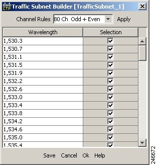

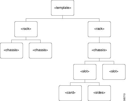
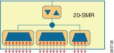
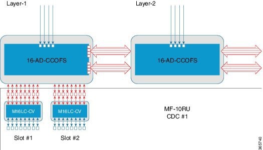
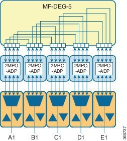
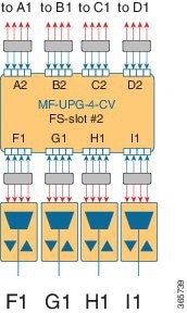

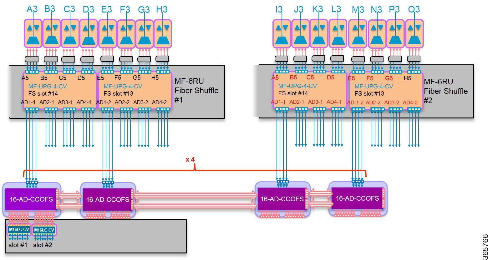
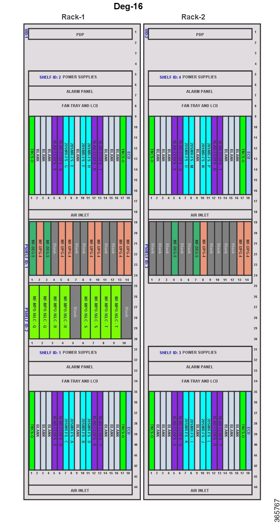
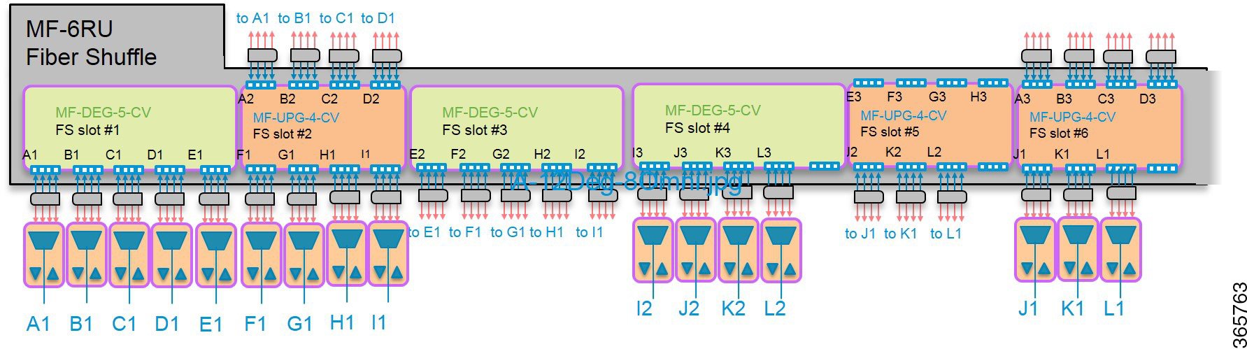
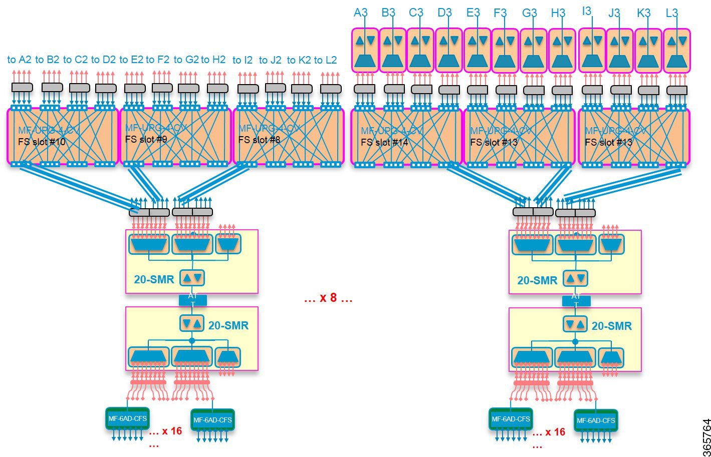
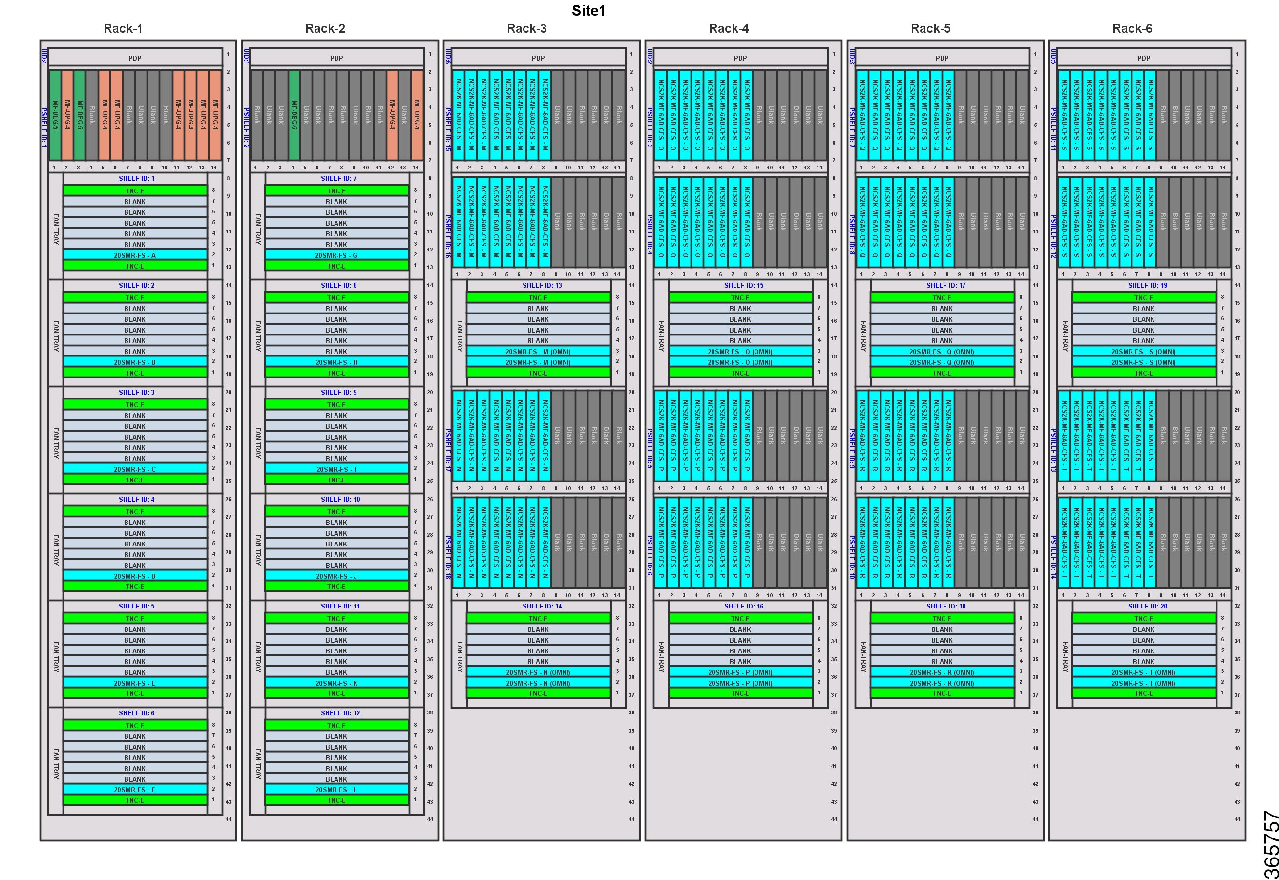
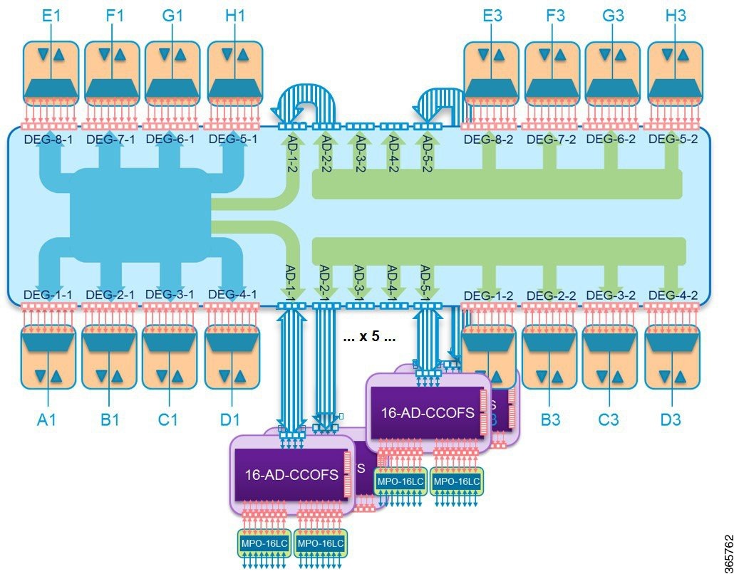
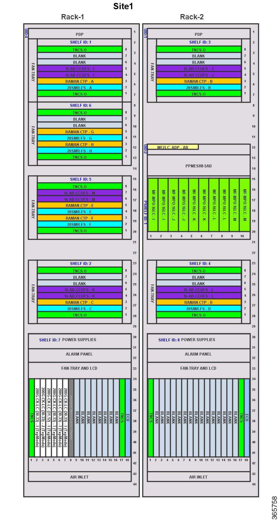

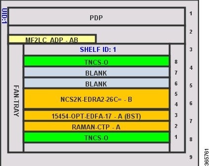
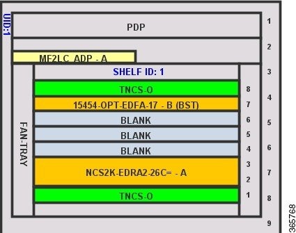
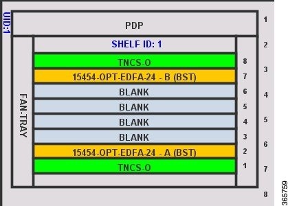
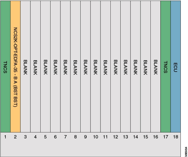
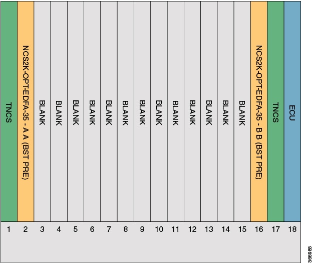

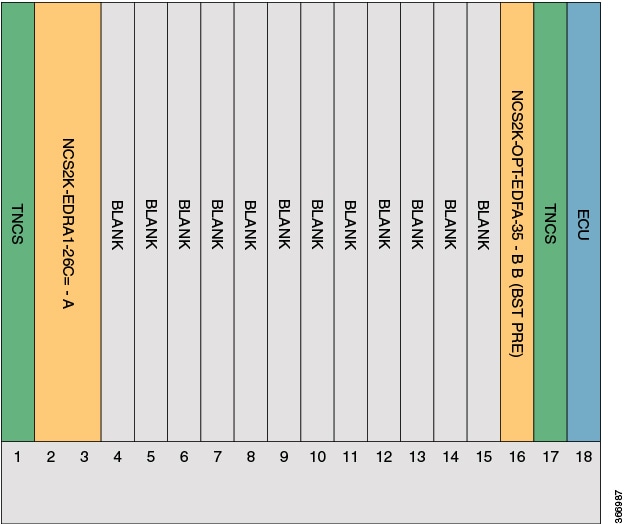

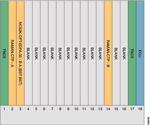
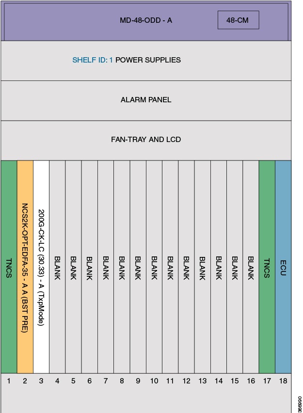
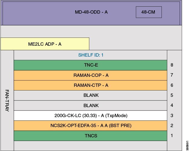


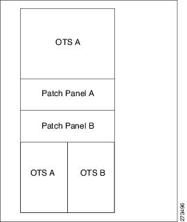


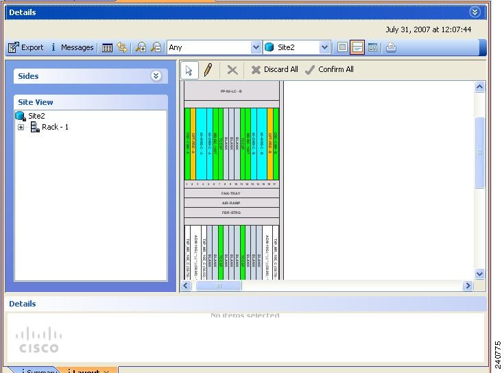


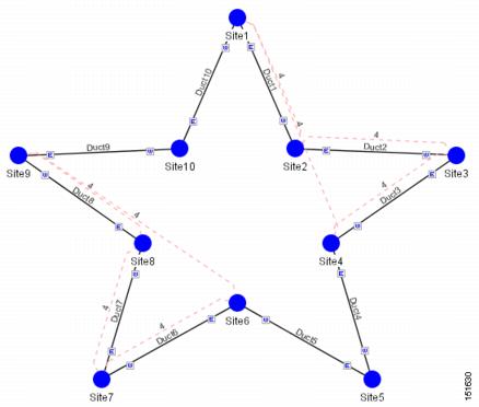

 Feedback