Interface Operative Area
In the Cisco Transport Planner interface model, the operative area of an interface is defined on a two-dimensional Cartesian plane where the x-axis is the optical signal-to-noise ratio (OSNR) value (dB) and y-axis is the receiver (Rx) power value (dBm). Three lines border the operative area. These lines are an approximation of the ISO-Bit Error Rate (BER) curve corresponding to the maximum BER tolerable by the interface:
-
On the original ISO-BER curve there are two points, OL and PL, that define the two main borders: OSNR limited (OL) and power limited (PL).
-
The upper boundary of the OSNR-limited border is the interface power overload; this is also the upper limit to the working area. Physical constraints limit this value to 35 to 40 dB.
The following figure shows the working area in an interface.
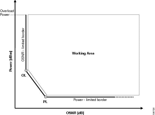
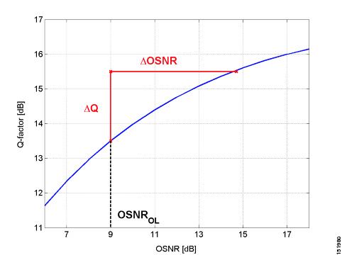
Signal impairments reduce the operative area of the interface. Because of signal distortion, higher OSNR and/or power on the Rx are required to get the same BER. When the power and OSNR margins are increased, OL and PL identify a new working area as shown in the following figure.

To define a third-party client interface, you enter parameters in Cisco Transport Planner that build the working area and model its robustness to signal impairments such as dispersion, single interfering, Gaussian cross talk (Xt), etc. The input parameters follow:
-
Transmitter Characteristics:
-
Modulation Format— Non Return to Zero (NRZ), Duo Binary, Differential Phase Shift keying (DPSK), Binary PSK (BPSK), Differential Quadrature PSK-RZ (DQPSK-RZ), Polarization Multiplexed-DQPSK (PM-DQPSK), Coherent Polarized-QPSK (CP-QPSK), 8 States-Quadrature Amplitude Modulation (8-QAM), 16 States Quadrature Amplitude Modulation (16-QAM), Set Partitioning 16-QAM (SP16-QAM), SP_16QAM_16QAM (Hybrid), QPSK _SP_16QAM (Hybrid), QPSK_SP_16QAM (Hybrid) or QAM16_QAM32 (Hybrid)
-
Transmitter Type—Mach Zehnder (MZ), Direct Modulated Laser (DML), or Electro-absorption Modulated Laser (EML)
-
Receiver Threshold—Optimal (minimum BER) or Average (average received power)
-
Regeneration Type—3R or 2R regeneration mode
-
Forward Error Correction (FEC) Mode—FEC, Enhanced FEC (E-FEC), High-Gain FEC (HG-FEC), Soft-Decision FEC (SD-FEC) or none
-
Transmitter Stability—The maximum wavelength error allowed (pm)
-
-
Bit rate
-
Power range—Transmit (Tx) maximum and minimum power output levels (dBm)
-
Back-to-back receiver sensitivity—A configuration in which the receiver is placed in front of the transmitter with no other equipment between the two. Back to back is used to measure Tx and Rx pairs.
-
Overload power (dBm)
-
OL_power (dBm)—The minimum power level in the OSNR-limited range
-
OL_OSNR (dB)—The minimum OSNR level in the OSNR-limited range (measured on 0.5 nm bandwidth)
-
PL_power (dBm)—The minimum power level in the power-limited range
-
PL_OSNR (dB)—The minimum power level in the OSNL-limited range (measured in.5 nm increments)
-
-
Chromatic dispersion (CD)—The broadening of a light pulse after traveling a distance in the fiber. You can set the CD robustness [ps/nm], which is the maximum positive dispersion tolerable by the interface.
-
Scale value—Calculates how efficient a card is in recovering the signal distortion. For more information, see the Scale Factors.
. -
Single-interfering cross-talk penalties—Calculates interference caused by a single signal. For more information, see theSingle-Interfering Cross-Talk Penalty Measurement.
-
Gaussian cross-talk penalties—Calculates random power that interferes with a signal. For more information, see the Gaussian Cross-Talk Penalty Measurement.
Transmitter characteristics, bit rate, and back-to-back sensitivity parameters are required to create a third-party interface; the other parameters are optional. Cisco Transport Planner checks your input to determine if the third-party interface could be modeled on a card type already present in the software. If the interface is not supported, Transport Planner displays an error message. For the procedure to define third-party interfaces, see Defining Third-Party DWDM Interfaces.


 Feedback