Installing the 32WSS-L Card in the Cisco ONS 15454 SONET/SDH
Available Languages
Table Of Contents
Installing the 32WSS-L Card in the Cisco ONS 15454 SONET/SDH
Obtaining Documentation and Submitting a Service Request
Installing the 32WSS-L Card in the Cisco ONS 15454 SONET/SDH
Product Name: 15454-WSS-L
This document provides a card description, specifications, and installation procedure for the dense wavelength division multiplexer (DWDM) 32WSS-L card. The 32WSS-L card is compatible with Cisco ONS 15454 SONET (ANSI) and Cisco ONS 15454 SDH (ETSI) shelf assemblies. Use this document in conjunction with the Cisco ONS 15454 DWDM Procedure Guide when working with 32WSS-L cards.
This document contains the following sections:
•
Obtaining Documentation and Submitting a Service Request
32WSS-L Card Description
The 32-Channel Wavelength Selective Switch L-Band (32WSS-L) card performs channel add/drop processing within the ONS 15454 DWDM node. The 32WSS-L works in conjunction with the 32DMX-L to implement ROADM functionality within the L band (1570 to 1620 nm). The 32WSS-L card is well suited for use in networks that employ DS fiber or SMF-28 single-mode fiber. Equipped with ROADM functionality, a DWDM node can be configured to add or drop individual optical channels using Cisco Transport Controller (CTC), Cisco MetroPlanner, and Cisco Transport Manager (CTM).
An ROADM node utilizes two 32WSS-L cards (two slots each) and two 32DMX-L cards (one slot each), for a total of six slots in the chassis. For a diagram of a typical ROADM configuration, see the Cisco ONS 15454 DWDM Reference Manual. The two-slot 32WSS-L card can be installed in Slots 1 and 2, 3 and 4, 5 and 6, 12 and 13, 14 and 15, or 16 and 17.
The 32WSS-L has six types of ports:
•
ADD RX ports (1 to 32): These ports are used for adding channels. Each add channel is associated with an individual switch element that selects whether an individual channel is added. Each add port has optical power regulation provided by a VOA.
•
EXP RX port: The EXP RX port receives an optical signal from another 32WSS-L module in the same network element (NE).
•
EXP TX port: The EXP TX port sends an optical signal to the other 32WSS-L module within the NE.
•
COM TX port: The COM TX port sends an aggregate optical signal to a booster amplifier card (for example, OPT-BST) for transmission outside of the NE.
•
COM RX port: The COM RX port receives the optical signal from a preamplifier and sends it to the optical splitter.
•
DROP TX port: The DROP TX port sends the drop channels to the 32DMX-L card where the channels are further processed and dropped.
A terminal node can be configured using only a 32WSS-L card and a 32DMX-L card plugged into the east or west side of the shelf.
Faceplate
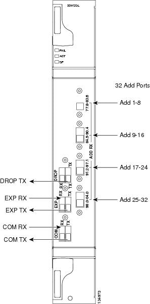
Figure 1 shows the 32WSS-L module front panel and identifies the traffic flow through the ports.
Figure 1 32WSS-L Faceplate

Block Diagrams
Figure 2 provides a high-level functional block diagram of the 32WSS-L card.
Figure 2 32WSS-L Block Diagram

Aggregate optical signals that enter the EXP RX and COM RX ports are processed in two ways. The optical processing stages are shown in Figure 3, which provides a detailed optical functional diagram of the 32WSS-L card.
Figure 3 32WSS-L Optical Functional Diagram

The EX PORT and COM PORT operate as follows:
•
EXP RX Port Add Channel/Pass-through Processing
The incoming optical signal is received at the EXP RX port from the other 32WSS-L module within the NE. The incoming aggregate optical signal is demultiplexed into 32 individual wavelength components, or channels. Then each channel is individually processed by the optical switch, which does add/pass-through processing. Under software control, the switch either selects the optical channel coming in from the demultiplexer (the pass-through channel) or it selects the external ADD channel. If the ADD port channel is selected, the optical signal coming from the demultiplexer is blocked, and the ADD channel is transmitted in its place.
After the optical switch stage, all of the channels are multiplexed together into an aggregate optical signal, which is sent out on the COM TX port. The output is typically connected to an OPT-AMP-L (in the event a booster amplifier is needed) or to an OSC-CSM (if no amplification is needed).
•
COM RX Port Optical Splitter Processing
The incoming optical signal received at the COM RX port is applied to the optical splitter within the 32WSS-L card. Channels that are designated to be dropped are diverted optically to the DROP TX port by the splitter. The DROP TX port on the 32WSS-L is typically connected to the COM RX port of the 32DMX-L where the drop channels are dropped. Channels that are not dropped pass through the optical splitter and flow out of the EXP TX port of the 32WSS-L card. This optical signal is typically connected to the other 32WSS-L module within the NE.
Power Monitoring
Physical photodiodes P1 through P69 monitor the power for the 32WSS-L card. The returned power level values are calibrated to the ports as shown in Table 1.
Channel Plan
The 32WSS-L card uses 32 channels on the ITU 100-GHz grid in a banded configuration (see Table 2).
32WSS-L Card Level Indicators
Table 3 describes the three card-level LED indicators on the 32WSS-L card.
32WSS-L Port-Level Indicators
You can find the status of the 32WSS-L card's ports using the LCD screen on the ONS 15454 ANSI fan-tray assembly. Use the LCD to view the status of any port or card slot; the screen displays the number and severity of alarms for a given port or slot.
The 32WSS-L card has five sets of ports located on the faceplate. COM RX is the line input, COM TX is the line output, EXP RX is the port where a channel can be added or passed through, EXP TX is the port that passes through the channels that are not dropped, and DROP TX is the port for the dropped channels. The xx.x to yy.y TX ports represent the four groups of eight channels ranging from the xx.x wavelength to the yy.y wavelenth according to the channel plan.
32WSS-L Card Specifications
The 32WSS-L card optical specifications are listed in Table 4.

Note
For power specifications, see Cisco ONS 15454 DWDM Reference Manual.
The 32WSS-L card has the following additional specifications:
•
Environmental
–
Operating temperature:
C-Temp: -5 to +55 degrees Celsius (+23 to +131 degrees Fahrenheit)
–
Operating humidity: 5 to 95 percent RH
•
Dimensions
–
Height: 12.65 in. (321.3 mm)
–
Width: 1.84 in. (46.8 mm)
–
Depth: 9.00 in. (228.6 mm)
Install the 32WSS-L Card
WarningClass 1M laser radiation when open. Do not view directly with optical instruments. Statement 1053

CautionAlways use the supplied ESD wristband when working with a powered ONS 15454. Plug the wristband cable into the ESD jack located on the lower-right outside edge of the shelf assembly.

Note
If protective clips are installed on the card connectors, remove the clips before installing the cards.

Note
If you install a card incorrectly, the FAIL LED flashes continuously.
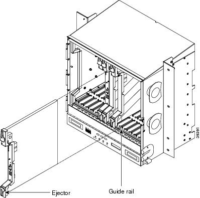
Figure 4 shows general card installation.
Figure 4 Installing a Card in the Cisco ONS 15454 (ANSI)

Step 1
Display the card installation plan for the node using one of the following sources:
•
The Cisco MetroPlanner Site Dialog window for the node you are provisioning.
•
CTC node view with slots preprovisioned based on the Cisco MetroPlanner Site Dialog window.
•
Written slot plan. The plan must be based on the Cisco MetroPlanner Site Dialog window for your installation.
Step 2
Remove the 32WSS-L card from its packaging, then remove the protective caps from the card's rear connectors.
Step 3
Open the card latches/ejectors.
Step 4
Use the latches/ejectors to firmly slide the card along the slot guide rails until the card plugs into the receptacle at the back of the slot.
Step 5
Verify that the card is inserted correctly and close the latches/ejectors on the card.

Note
It is possible to close the latches/ejectors when the card is not completely plugged into the backplane. Ensure that you cannot insert the card any further.
Step 6
Verify the LED activity:
•
The FAIL LED turns on for approximately 35 seconds.
•
The FAIL LED blinks for approximately 40 seconds.
•
All LEDs turn on and then turn off within 5 seconds.
•
If new software is being downloaded to the card, the ACT and SF LEDs blink for 20 seconds to 3.5 minutes, depending on the card type.
•
The ACT LED turns on.
•
The signal fail (SF) LED stays on until all card ports connect to their far-end counterparts and a signal is present.
Step 7
If the card does not boot up properly, or the LED activity does not mimic Step 6, check the following:
•
When a physical card type does not match the type of card provisioned for that slot in CTC, the card might not boot. If a 32WSS-L card does not boot, open CTC and ensure that the slot is not provisioned for a different card type before assuming that the card is faulty.
•
If the red FAIL LED does not turn on, check the power.
•
If you insert a card into a slot provisioned for a different card, all LEDs turn off.
•
If the red FAIL LED is on continuously or the LEDs behave erratically, the card is not installed. Remove the card and repeat Steps 3 to 7. If the card does not boot up properly the second time, it may be defective. Contact your next level of support.

Note
The DWDM node type is determined by the cards that are installed. For example, if two 32DMX-O and two 32MUX-O cards are installed but no AD-xC or AD-xB cards are installed, CTC considers the node a hub node. However, if one 32DMX-O and one 32MUX-O card is installed with no AD-xC or AD-xB cards, CTC considers the node a terminal node. For more information, refer to the iCisco ONS 15454 DWDM Reference Manual
Related Documentation
•
Cisco ONS 15454 DWDM Reference Manual
•
Cisco ONS 15454 DWDM Procedure Guide
•
Cisco ONS 15454 DWDM Troubleshooting Guide
•
Cisco MetroPlanner DWDM Operations Guide
Obtaining Documentation and Submitting a Service Request
For information on obtaining documentation, submitting a service request, and gathering additional information, see the monthly What's New in Cisco Product Documentation, which also lists all new and revised Cisco technical documentation, at:
http://www.cisco.com/en/US/docs/general/whatsnew/whatsnew.html
Subscribe to the What's New in Cisco Product Documentation as a Really Simple Syndication (RSS) feed and set content to be delivered directly to your desktop using a reader application. The RSS feeds are a free service and Cisco currently supports RSS Version 2.0.
This document is to be used in conjunction with the documents listed in the "Related Documentation" section

© 2005 Cisco Systems, Inc. All rights reserved.
Printed in the USA on recycled paper containing 10% postconsumer waste.


 Feedback