Installing the Power Board in the Ethernet Switch Network Modules
Available Languages
Table Of Contents
Installing the Power Board in the Cisco Ethernet Switch Network Modules
Internal Power Supplies for Cisco 3700 Series Routers
External Power Supplies for Cisco 2600 Series and Cisco 3600 Series Routers
Installing the Power Board in the Cisco Ethernet Switch Network Modules
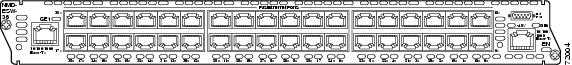
This chapter explains how to install the power board on the Ethernet switch network module. This optional power board can be added to provide inline power for IP telephones. The power board is connected to an external power supply using a power connection cable. The front of the16-port network module is shown in Figure 4-1 and the front of the 36-port network module is shown in Figure 4-2.
Figure 4-1 16-Port Cisco Ethernet Switch Network Module
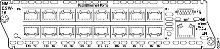
Figure 4-2 36-Port Cisco Ethernet Switch Network Module
Power Considerations
The Cisco Ethernet switch network module supports inline powering of IP telephones with -48V power. This allows IP phones to be plugged into the standard RJ-45 jack and be powered from this source rather than having a separate plug into an AC wall outlet. -48V must be delivered to the Cisco Ethernet switch network module in order to meet this requirement.
Cisco 3700 series routers supply -48V power internally to the Cisco Ethernet switch network module. To support Cisco 2600 series and Cisco 3600 series router that do not supply -48V internal power, the network module also has an external connector to connect to an external -48V power supply.
The Cisco Ethernet switch network module distributes the -48V power to each of the Ethernet ports which are configured for line power. Each port can be independently configured for line power.
Internal Power Supplies for Cisco 3700 Series Routers
Cisco 3700 series routers contain internal -48V power supplies to supply power to the Cisco Ethernet switch network module.
For the Cisco 3745 router, the following specifications apply:
•
The Cisco 3745 router can have 1 or 2 internal -48V power supplies. The internal supplies of Cisco 3745 router are configured to be redundant by default.
•
•
Cisco 3725 routers have a single, -48V supply. Cisco 3725 routers do not report any power supply status. Software's only indication of -48V status will be the -48V status bit provided on the 16-port Cisco Ethernet switch network module board.
External Power Supplies for Cisco 2600 Series and Cisco 3600 Series Routers
Cisco 2600 series and Cisco 3600 series routers do not supply -48V power so an external -48V supply is required to support inline power for IP phones. This external power supply connects to the Cisco Ethernet switch network module faceplate with a cable.
An external power supply plugged into a Cisco Ethernet switch network module provides power only for that specific network module. To supply redundant power, a Y cable can be used so that two external power supplies are connected to the same card.
Adding a Power Board
An optional power board should be installed if the Cisco Ethernet switch network module requires external -48V power for IP telephones.
Follow this procedure to install a power board:
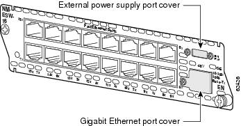
Step 1
Figure 4-3 Power Board Port Cover on the Cisco Ethernet Switch Network Module
Step 2
Step 3
Step 4

Note
Step 5
Step 6

Warning
Step 7
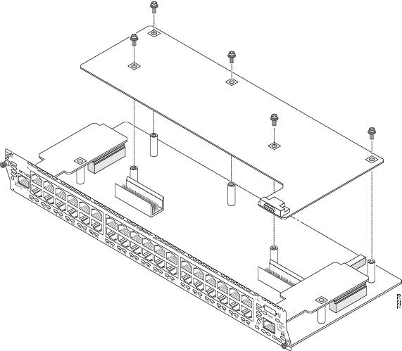
Figure 4-4 Installing a Power Board in a 16-Port Cisco Ethernet Switch Network Module
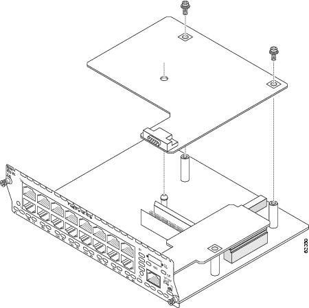
Figure 4-5 Installing a Power Board in a 36-Port Cisco Ethernet Switch Network Module
 Feedback