- Overview of the Cisco 819 Integrated Services Router
- Wireless Device Overview
- Wireless Local Area Network
- 4G LTE Wireless WAN
- Basic Router Configuration
- Configuring Backup Data Lines and Remote Management
- Environment Monitoring
- Configuring the Serial Interface
- Configuring Security Features
- Configuring the Ethernet Switches
- Configuring PPP over Ethernet with NAT
- Configuring a LAN with DHCP and VLANs
- Configuring a VPN Using Easy VPN and an IPSec Tunnel
- Cisco IOS Software Basic Skills
- Concepts
- ROM Monitor
- Common Port Assignments
Cisco 819 Integrated Services Routers Software Configuration Guide
Bias-Free Language
The documentation set for this product strives to use bias-free language. For the purposes of this documentation set, bias-free is defined as language that does not imply discrimination based on age, disability, gender, racial identity, ethnic identity, sexual orientation, socioeconomic status, and intersectionality. Exceptions may be present in the documentation due to language that is hardcoded in the user interfaces of the product software, language used based on RFP documentation, or language that is used by a referenced third-party product. Learn more about how Cisco is using Inclusive Language.
- Updated:
- March 14, 2016
Chapter: Configuring a LAN with DHCP and VLANs
Configuring a LAN with DHCP and VLANs
The Cisco 819 Integrated Services Routers (ISRs) support clients on both physical LANs and virtual LANs (VLANs). The routers can use the Dynamic Host Configuration Protocol (DHCP) to enable automatic assignment of IP configurations for nodes on these networks.
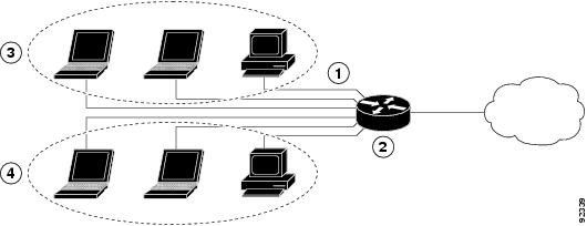
Figure 12-1 shows a typical deployment scenario with two physical LANs connected by the router and two VLANs.
Figure 12-1 Physical and Virtual LANs with DHCP Configured on the Cisco Router
|
|
|
|
|
Router and DHCP server—Cisco 819 ISR—connected to the Internet |
|
|
|
|
|
DHCP
DHCP, which is described in RFC 2131, uses a client/server model for address allocation. As an administrator, you can configure your Cisco 800 series router to act as a DHCP server, providing IP address assignment and other TCP/IP-oriented configuration information to your workstations. DHCP frees you from having to manually assign an IP address to each client.
When you configure a DHCP server, you must configure the server properties, policies, and DHCP options.

Note![]() Whenever you change server properties, you must reload the server with the configuration data from the Network Registrar database.
Whenever you change server properties, you must reload the server with the configuration data from the Network Registrar database.
VLANs
The Cisco 819 routers support four Fast Ethernet ports on which you can configure VLANs.
VLANs enable networks to be segmented and formed into logical groups of users, regardless of the user’s physical location or LAN connection.
Configuration Tasks
Perform the following tasks to configure this network scenario:
Note![]() The procedures in this chapter assume you have already configured basic router features, as well as PPPoE or PPPoA with NAT. If you have not performed these configurations tasks, see the “Basic Router Configuration” section and “Configuring a VPN Using Easy VPN and an IPSec Tunnel” section as appropriate for your router.
The procedures in this chapter assume you have already configured basic router features, as well as PPPoE or PPPoA with NAT. If you have not performed these configurations tasks, see the “Basic Router Configuration” section and “Configuring a VPN Using Easy VPN and an IPSec Tunnel” section as appropriate for your router.
Configure DHCP
Perform these steps to configure your router for DHCP operation, beginning in global configuration mode:
SUMMARY STEPS
2.![]() ip name-server server-address1 [s erver-address2...server-address6 ]
ip name-server server-address1 [s erver-address2...server-address6 ]
3.![]() ip dhcp excluded-address low-address [ high-address ]
ip dhcp excluded-address low-address [ high-address ]
5.![]() network network-number [ mask | prefix-length ]
network network-number [ mask | prefix-length ]
7.![]() default-router address [ address2...address8 ]
default-router address [ address2...address8 ]
DETAILED STEPS
Configuration Example
The following configuration example shows a portion of the configuration file for the DCHP configuration described in this chapter:
Verify Your DHCP Configuration
Use the following commands to view your DHCP configuration.
- show ip dhcp import —Displays the optional parameters imported into the DHCP server database.
- show ip dhcp pool —Displays information about the DHCP address pools.
- show ip dhcp server statistics —Displays the DHCP server statistics, such as the number of address pools, bindings, and so forth.
Configure VLANs
Perform these steps to configure VLANs on your router, beginning in global configuration mode:
SUMMARY STEPS
DETAILED STEPS
|
|
|
|
|---|---|---|
|
|
||
vlan)#
|
Adds VLANs, with identifiers ranging from For details about this command and additional parameters that can be set, see Cisco IOS Switching Services Command Reference. |
|
vlan)#
exit
|
Updates the VLAN database, propagates it throughout the administrative domain, and returns to global configuration mode. |
Assign a Switch Port to a VLAN
Perform these steps to assign a switch port to a VLAN, beginning in global configuration mode:
SUMMARY STEPS
DETAILED STEPS
Verify Your VLAN Configuration
Use the following commands to view your VLAN configuration.
- show —Entered from VLAN database mode. Displays summary configuration information for all configured VLANs.
- show vlan-switch—Entered from privileged EXEC mode. Displays detailed configuration information for all configured VLANs.
Name: VLAN0002
Media Type: Ethernet
VLAN 802.10 Id: 100002
State: Operational
MTU: 1500
Name: red-vlan
Media Type: Ethernet
VLAN 802.10 Id: 100003
State: Operational
MTU: 1500
 Feedback