Cisco VG224 Voice Gateway Hardware Installation Guide
Bias-Free Language
The documentation set for this product strives to use bias-free language. For the purposes of this documentation set, bias-free is defined as language that does not imply discrimination based on age, disability, gender, racial identity, ethnic identity, sexual orientation, socioeconomic status, and intersectionality. Exceptions may be present in the documentation due to language that is hardcoded in the user interfaces of the product software, language used based on RFP documentation, or language that is used by a referenced third-party product. Learn more about how Cisco is using Inclusive Language.
- Updated:
- October 11, 2004
Chapter: Cable Specifications and Information
Cable Specifications and Information
This appendix provides the connector and pinout information you need for making or purchasing cables used with Cisco VG224 voice gateway. To order cables from Cisco, see the "Obtaining Technical Assistance" section on page xvi. This appendix contains the following sections:
•![]() Console and Auxiliary Port Cables and Pinouts
Console and Auxiliary Port Cables and Pinouts
•![]() Fast Ethernet Port Pinouts (RJ-45)
Fast Ethernet Port Pinouts (RJ-45)
•![]() Analog Voice Multiport Pinouts (RJ-21X/CA21A)
Analog Voice Multiport Pinouts (RJ-21X/CA21A)
The following list shows you which table to see for pinout information:
|
|
|
|---|---|
Console Port to ASCII Terminal—Cable Pinouts (RJ-45 to DB-25) |
|
Console and Auxiliary Port Cables and Pinouts
Your Cisco VG224 voice gateway comes with the cable and adapters you need to connect a PC, an ASCII terminal, or a modem to your Cisco VG224 voice gateway. The cable kit includes:
•![]() RJ-45-to-RJ-45 rollover cable
RJ-45-to-RJ-45 rollover cable
•![]() RJ-45-to-DB-9 adapter cable for console connection
RJ-45-to-DB-9 adapter cable for console connection
•![]() RJ-45-to-DB-25 adapter cable for modem connection
RJ-45-to-DB-25 adapter cable for modem connection
The following illustrations and tables provide cable pinout information:
•![]() Console port to a PC—See Table A-1 and Table A-4
Console port to a PC—See Table A-1 and Table A-4
•![]() Console port to an ASCII terminal—See Table A-2 and Table A-4
Console port to an ASCII terminal—See Table A-2 and Table A-4
•![]() Auxiliary port to a modem—See Table A-3 and Table A-4
Auxiliary port to a modem—See Table A-3 and Table A-4
The console port is configured as data communications equipment (DCE); the auxiliary port is configured as data terminal equipment (DTE). Both are asynchronous serial ports and use RJ-45 connectors.
Identifying a Rollover Cable
You can identify a rollover cable by holding the plugs side by side, with the tab at the back and comparing the modular plugs at the two ends of the cable. The wire connected to the pin on the outside of the left plug should be the same color as the wire connected to the pin on the outside of the right plug. (See Figure A-1.)
If your cable comes from Cisco Systems, pin 1 is white on one plug, and pin 8 is white on the opposite plug. (A rollover cable reverses the wire connections at the opposite ends: 1 to 8, 2 to 7, 3 to 6, 4 to 5, 5 to 4, 6 to 3, 7 to 2, and 8 to 1.)
Figure A-1 Identifying a Rollover Cable

Console Port to PC
Figure A-2 shows the RJ-45-to-RJ-45 rollover cable assembly and the RJ-45-to-DB-9 female DTE adapter (labeled TERMINAL); Table A-1 lists the pinouts.
Figure A-2 Console Port to PC—Cable and Adapter

|
|
|
|
|
||
|---|---|---|---|---|---|
|
|
|
|
|
|
|
RTS |
11 |
8 |
8 |
8 |
CTS |
DTR |
2 |
7 |
7 |
6 |
DSR |
TxD |
3 |
6 |
6 |
2 |
RxD |
GND |
4 |
5 |
5 |
5 |
GND |
GND |
5 |
4 |
4 |
5 |
GND |
RxD |
6 |
3 |
3 |
3 |
TxD |
DSR |
7 |
2 |
2 |
4 |
DTR |
CTS |
81 |
1 |
1 |
7 |
RTS |
1 Pin 1 is connected to pin 8 inside the Cisco VG224 voice gateway. |
Console Port to ASCII Terminal
Figure A-3 shows the RJ-45-to-RJ-45 rollover cable assembly and the RJ-45-to-DB-25 female DTE adapter (labeled TERMINAL); Table A-2 lists the pinouts.
Figure A-3 Console Port to ASCII Terminal—Cable and Adapter

|
|
|
|
|
||
|---|---|---|---|---|---|
|
|
|
|
|
|
|
RTS |
11 |
8 |
8 |
5 |
CTS |
DTR |
2 |
7 |
7 |
6 |
DSR |
TxD |
3 |
6 |
6 |
3 |
RxD |
GND |
4 |
5 |
5 |
7 |
GND |
GND |
5 |
4 |
4 |
7 |
GND |
RxD |
6 |
3 |
3 |
2 |
TxD |
DSR |
7 |
2 |
2 |
20 |
DTR |
CTS |
81 |
1 |
1 |
4 |
RTS |
1 Pin 1 is connected to pin 8 inside the Cisco VG224 voice gateway. |
Auxiliary Port to Modem
Figure A-4 shows the RJ-45-to-RJ-45 rollover cable assembly and the RJ-45-to-DB-25 male DCE adapter (labeled MODEM); Table A-3 lists the pinouts.
Figure A-4 Auxiliary Port to Modem—Cable and Adapter

Alternative Connections to Terminal and Modem
Your Cisco VG224 voice gateway ships with an RJ-45-to-RJ-45 rollover cable and two adapters for connection to a PC, a terminal, or a modem. If you want to use an RJ-45 straight-through cable or other adapters, see Table A-4 for usable cable and adapter combinations.
|
|
|
|
|---|---|---|
Console port to PC |
Straight-through |
DCE, DB-9 female |
Auxiliary port to modem |
Rollover1 |
DCE2 , DB-25, male |
Straight-through |
DTE2, DB-25, male |
1 An octal cable or RJ-45 breakout cable is equivalent to a rollover cable. 2 Modify the DB-25 adapter by removing the wire in pin 6 and placing it in the pin 8 position. |
Fast Ethernet Port Pinouts (RJ-45)
Figure A-5 shows the RJ-45 connector wiring for the Fast Ethernet cable; Figure A-5 lists the pinouts.

Note ![]() Pinout shown is for category 3, 4, or 5 10/100BASE-T connection to an Fast Ethernet switch.
Pinout shown is for category 3, 4, or 5 10/100BASE-T connection to an Fast Ethernet switch.
Figure A-5 RJ-45 Connector Wiring

|
|
|
|---|---|
1 |
TX+ |
2 |
TX- |
3 |
RX+ |
4 |
- |
5 |
- |
6 |
RX- |
7 |
- |
8 |
- |
1 Any pin not referenced is not connected. |
Analog Voice Multiport Pinouts (RJ-21X/CA21A)
Figure A-6 shows the RJ-21 connector wiring for the cable used for the multiport analog voice interface.
Figure A-6 RJ-21 Connector Wiring
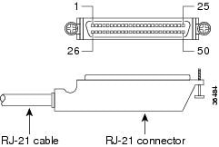
Table A-6 lists the pinouts for the RJ-21 connector.
EIA/TIA-232 Connections
The EIA/TIA-232 standard supports unbalanced circuits at signal speeds up to 64 kbps.
For connection to a Cisco VG224 voice gateway serial port, use the EIA/TIA-232 serial transition cable with the Cisco 12-in-1 connector on one end and a DB-25 connector (as shown in Figure A-7) on the other. The DB-25 connector can be male for DTE or female for DCE. To order a cable, see the "Obtaining Technical Assistance" section on page xvi.
Figure A-7 EIA/TIA-232 Serial Transition Cable Connectors

EIA/TIA-449 Connections
The EIA/TIA-449 standard, which supports balanced and unbalanced transmissions, is a faster (up to 2 Mbps) version of the EIA/TIA-232 standard that provides more functions and supports transmission over greater distances.
The EIA/TIA-449 standard was intended to replace the EIA/TIA-232 standard. However, this standard was not widely adopted because of the large installed base of DB-25 hardware. Also, the larger size of the 37-pin EIA/TIA-449 connectors limited the number of connections possible (fewer than are possible with the smaller, 25-pin EIA/TIA-232 connector).
To make a connection to a Cisco VG224 voice gateway serial port, use the EIA/TIA-449 serial transition cable with the Cisco 12-in-1 connector on one end and a DB-37 connector (as shown in Figure A-8) on the other. The DB-37 connector can be male for DTE or female for DCE. To order a cable, see the "Obtaining Technical Assistance" section on page xvi.
Figure A-8 EIA/TIA-449 Serial Transition Cable Connectors

V.35 Connections
The V.35 standard is recommended for speeds up to 48 kbps, although in practice it is used successfully at 4 Mbps. The Cisco VG224 voice gateway supports speeds up to 2.048 Mbps.
Use the V.35 serial transition cable (not included) with the Cisco 12-in-1 connector on one end and a standard 34-pin Winchester-type connector (as shown in Figure A-9) on the other. The 34-pin Winchester-type connector can be male for DTE or female for DCE. To order a cable, see the "Obtaining Technical Assistance" section on page xvi.
Figure A-9 V.35 Serial Transition Cable Connectors

X.21 Connections
The X.21 connector uses a 15-pin connector for balanced circuits and is commonly used in the United Kingdom to connect to the public data network. X.21 relocates some of the logic functions to the DTE and DCE interfaces and, as a result, requires fewer circuits and a smaller connector than EIA/TIA-232.
Use the X.21 serial transition cable (not included) with the Cisco 12-in-1 connector on one end and a DB-15 connector (as shown in Figure A-10) on the other. The DB-15 connector can be male for DTE or female for DCE. To order a cable, see the "Obtaining Technical Assistance" section on page xvi.
Figure A-10 X.21 Serial Transition Cable Connectors

EIA/TIA-530 Connections
The EIA/TIA-530 standard, which supports balanced transmission, provides the increased functionality, speed, and distance of EIA/TIA-449 on the smaller, DB-25 connector used for EIA/TIA-232. Like EIA/TIA-449, EIA/TIA-530 refers to the electrical specifications of EIA/TIA-422 and EIA/TIA-423. Although the specification recommends a maximum speed of 2 Mbps, EIA/TIA-530 is used successfully at 4 Mbps or faster speeds over short distances. Cisco VG224 voice gateway supports speeds up to 2.048 Mbps.
Use the EIA/TIA-530 serial transition cable (not included) with the Cisco 12-in-1 connector on one end and a DB-25 connector (as shown in Figure A-11) on the other. The DB-25 connector can be male for DTE or female for DCE. To order a cable, see the "Obtaining Technical Assistance" section on page xvi.
Figure A-11 EIA/TIA-530 Serial Transition Cable Connectors
 Feedback