Cisco VG350 Voice Gateway Hardware Installation Guide
Bias-Free Language
The documentation set for this product strives to use bias-free language. For the purposes of this documentation set, bias-free is defined as language that does not imply discrimination based on age, disability, gender, racial identity, ethnic identity, sexual orientation, socioeconomic status, and intersectionality. Exceptions may be present in the documentation due to language that is hardcoded in the user interfaces of the product software, language used based on RFP documentation, or language that is used by a referenced third-party product. Learn more about how Cisco is using Inclusive Language.
- Updated:
- March 27, 2014
Chapter: Cisco Double-wide High Density Analog Service Modules
Cisco Double-Wide High Density Analog
Service Modules
This chapter provides information about the following Double-Wide High Denstiy Analog Service Module (DWSM).
1.![]() Cisco SM-D-72FXS Service Module—A 72 FXS port DWSM with 4 out of the 72 ports supporting OPX ‘Lite’ capabilities.
Cisco SM-D-72FXS Service Module—A 72 FXS port DWSM with 4 out of the 72 ports supporting OPX ‘Lite’ capabilities.
2.![]() Cisco SM-D-48FXS-E Service Module—A 48 FXS port DWSM with all 48 ports supporting OPX Lite capabilities.
Cisco SM-D-48FXS-E Service Module—A 48 FXS port DWSM with all 48 ports supporting OPX Lite capabilities.

Note DWSM refers to both the Cisco SM-D-72FXS and SM-D-48FXS-E Service Module.
Double-Wide High Density Analog Service Module Overview
The Double-Wide High Density Service Module (DWSM) is supported on the following platforms:
The modules can be plugged in the following DWSM slots of the following platforms:
- On Cisco 3945 and Cisco 3945e - only on slot 4.
- On Cisco 3925, Cisc0 3925e and Cisco 2951 - only on slot 2.
Table 2-1 shows the comparison between Cisco SM-D-72FXS and SM-D-48FXS-E.
Table 2-1 Feature comparison of SM-D-72FXS and SM-D-48FXS-E
|
1.Each FXO Bypass Port are made up of two RJ-11 connectors for PSTN In and Out. |
Installing SM-D-72FXS
Install the SM-D-72FXS according to the instructions in the Installing Cisco Interface Cards in Cisco Access Routers document.
Grounding
Ensure that the equipment you are working with is properly grounded according to the instructions in the Installing Cisco Interface Cards in Cisco Access Routers document.
Cables
The VG350 Voice Gateway uses RJ-21 cables to connect to a distribution box.

Warning To avoid electric shock, do not connect safety extra-low voltage (SELV) circuits to telephone-network voltage (TNV) circuits. LAN ports contain SELV circuits, and WAN ports contain TNV circuits. Some LAN and WAN ports both use RJ-45 connectors. Use caution when connecting cables. Statement 1021
Warning Hazardous network voltages are present in WAN ports regardless of whether power to the unit is OFF or ON. To avoid electric shock, use caution when working near WAN ports. When detaching cables, detach the end away from the unit first. Statement 1026
Warning This equipment contains a ring signal generator (ringer), which is a source of hazardous voltage. Do not touch the RJ-11 (phone) port wires (conductors), the conductors of a cable connected to the RJ-11 port, or the associated circuit-board when the ringer is active. The ringer is activated by an incoming call. Statement 1042
Warning For connections outside the building where the equipment is installed, the following ports must be connected through an approved network termination unit with integral circuit protection: FXS. Statement 1044
Connecting SM-D-72FXS
To connect the SM-D-72FXS, follow the these steps:
Step 1![]() Confirm that the router is turned off.
Confirm that the router is turned off.
Step 2![]() Connect one end of the straight-through RJ-21 cable to an RJ-21 distribution box.
Connect one end of the straight-through RJ-21 cable to an RJ-21 distribution box.
Step 3![]() Connect the distribution box ports to a telephone or FAX machine using RJ-11 cable.
Connect the distribution box ports to a telephone or FAX machine using RJ-11 cable.
Installing SM-D-48FXS-E
Install the SM-D-72FXS according to the instructions in the Installing Cisco Interface Cards in Cisco Access Routers document.
Grounding
Ensure that the equipment you are working with is properly grounded according to the instructions in the Installing Cisco Interface Cards in Cisco Access Routers document.
Cables
The VG350 Voice Gateway uses RJ-21 cables to connect to a distribution box.
Warning To avoid electric shock, do not connect safety extra-low voltage (SELV) circuits to telephone-network voltage (TNV) circuits. LAN ports contain SELV circuits, and WAN ports contain TNV circuits. Some LAN and WAN ports both use RJ-45 connectors. Use caution when connecting cables. Statement 1021
Warning Hazardous network voltages are present in WAN ports regardless of whether power to the unit is OFF or ON. To avoid electric shock, use caution when working near WAN ports. When detaching cables, detach the end away from the unit first. Statement 1026
Warning This equipment contains a ring signal generator (ringer), which is a source of hazardous voltage. Do not touch the RJ-11 (phone) port wires (conductors), the conductors of a cable connected to the RJ-11 port, or the associated circuit-board when the ringer is active. The ringer is activated by an incoming call. Statement 1042
Warning For connections outside the building where the equipment is installed, the following ports must be connected through an approved network termination unit with integral circuit protection: FXS. Statement 1044
Connecting SM-D-48FXS-E
To connect the SM-D-48FXS-E, follow the these steps:
Step 1![]() Confirm that the router is turned off.
Confirm that the router is turned off.
Step 2![]() Connect one end of the straight-through RJ-21 cable to an RJ-21 distribution box.
Connect one end of the straight-through RJ-21 cable to an RJ-21 distribution box.
Step 3![]() Connect the distribution box ports to a telephone or FAX machine using an RJ-11 cable.
Connect the distribution box ports to a telephone or FAX machine using an RJ-11 cable.
FXO Fail-Over Bypass Ports
Bypass/Failover Port, also called Fail-over Trunk Bypass, provides a way to use designated analog phone ports to make phone calls through the Public Switch Telephone Network (PSTN) during power-outage or power savings circumstances.
Table 2-2 Table 2-2 Table 2-2shows the RJ-11 connector assignment.
Cisco SM-D-72FXS Service Module Specifications
Physical Description and LEDs
All interface ports and LEDs are on the rear of the chassis. Figure 2-1 illustrates their locations.
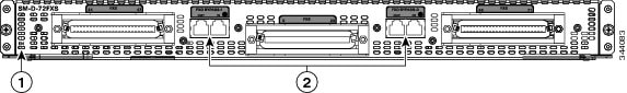
Figure 2-1 Cisco SM-D-72FXS Service Module LEDs
Cisco SM-D-48FXS-E Service Module Specifications
Physical Description and LEDs
All interface ports and LEDs are on the rear of the chassis. Figure 2-2 illustrates their locations.
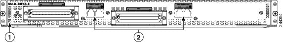
Figure 2-2 Cisco SM-D-48FXS-E Service Module LEDs
Port Numbering Conventions
Port numbering conventions for the Cisco VG350 Voice Gateway are as follows:
- Two Compact Flash slots, CF0 and CF1.
- GE ports are 10/100/1000 BASE-T, numbered GE 0/0 through GE 0/2.
- 10/100BASE-T ports are numbered 10/100BASE-T 0/0 and 10/100BASE-T 0/1 from right to left.
- FXS voice port numbering begins at 2/0/0 to 2/0/71 or 2/0/47 and 4/0/0 to 4/0/71 or 4/0/47, depending on the number of voice ports.
The ports numbered 2/0/x are for the SM installed in slot 1 and the ports numbered 4/0/x are for the Service Module (SM) installed in slot 2.
Connecting to the Double-Wide High Density Service Module Ports
Three RJ-21 female connectors are available on the SM-D-72FXS service module. The middle RJ-21 connector accesses FXS ports 0 to 23, the left RJ-21 female connector accesses ports 24 to 4, and the right RJ-21 connector accesses ports 48 to 71. Use RJ-21 male connector to connect from the DWSM RJ-21 ports to an FXS port RJ-11 distribution box.
Note Use an RJ-21 cable with Amphenol 50-pin connectors.
Online Insertion and Removal
The DWSM can be hot-inserted into the VG350 Voice Gateway without any potential of electrical damage either to the SM or the Host because the Online Insertion and Removal (OIR) logic is present on all SM designs.
OIRl is the ability to insert and remove an SM while the system is running without causing electrical damage to the SM or Host and without interfering with the operation of any other modules or portions of a running system.
The basic feature for OIR support on an SM is the control and isolation of the 12V power rail via a field-effect transistor (FET). This FET is enabled in a controlled fashion after the SM card is fully inserted.
Insertion and Removal Steps
This section describes the sequence of steps when inserting or removing a DWSM. OIR can only be done on one service module at a time. It only supports the same service module type. If you remove an SM-D-72FXS, only another SM-D-72FXS can be inserted.
Insertion
The following steps show how to insert a service module.
1.![]() Insert the service module into the slot.
Insert the service module into the slot.
2.![]() Make sure that the following message is displayed:
Make sure that the following message is displayed:
Note There are about 72 or 48 messages being displayed so it may take some time for the message to appear. Estimated waiting time is approximately 2 minutes.
3.![]() Use the following command to verify the voice ports after insertion.
Use the following command to verify the voice ports after insertion.
Removal
The following steps show how to remove a service module.
1.![]() Ensure there is no active call on the service module that you want to remove.
Ensure there is no active call on the service module that you want to remove.
Use the following command to find any active call in the system:
2.![]() Use the following command to proceed:
Use the following command to proceed:
where x is the slot number of the Service Module
 Feedback