


Pre-assembly of Plenum Before Mounting in Rack
Summary of Installation
- The plenum base is pre-assembled with the air baffles and air deflector outside the rack.
- The plenum base is inserted from the rear of the 19-inch rack. The plenum can be inserted from the front or rear of the 23-inch rack.
- The router is installed in the rack.
Follow these steps to pre-assemble the air plenum kit before mounting in the 19-inch or 23-inch rack.
SUMMARY STEPS
- Prepare the components of the air plenum kit for installation. If you are installing a Cisco ASR 9000v satellite shelf in the rack, remove the adjustment plate and M4 x 8mm pan-head screws from the left and right air baffles and discard them, two screws per adjustment plate.
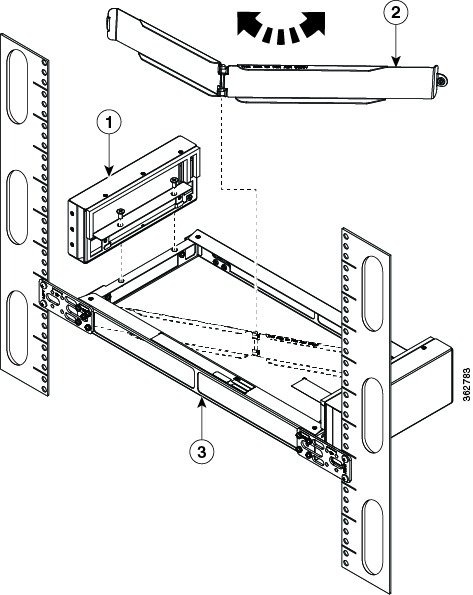
- Attach the left and right air baffles to the plenum base with vertical screws, using the four Cisco supplied M4 x 6mm flat-head screws (two per baffle). See this figure.
- Attach the air deflector to the plenum base using two pan-head M4 x 8mm pan-head screws, as shown in the figure Attaching Air Deflector to Plenum Base-Cisco ASR 9000v Satellite Shelf Orientation Shown .
- If installing from the rear of the 19-inch or 23-inch rack:
- If installing from the front of the 23-inch rack:
- Using the Cisco-supplied grounding lug, construct a suitable ground cable of sufficient length. Attach the grounding lug to the rear of the plenum base using two Cisco supplied M4 x 8mm pan-head screws and attach the other end to the grounding source. See the figure Mounting Plenum Assembly in Rack and Attaching Grounding Lug-Cisco ASR 9000v Satellite Shelf Orientation Shown .
- Install the router in the rack. See the Installing the Cisco ASR 9000v Satellite Shelf and the Mounting the Cisco ASR 901 Router for more information. This figure shows the Cisco ASR 9000v satellite shelf and air plenum kit installed in the rack.
DETAILED STEPS
|
Step 1 |
Prepare the components of the air plenum kit for installation. If you are installing a Cisco ASR 9000v satellite shelf in the rack, remove the adjustment plate and M4 x 8mm pan-head screws from the left and right air baffles and discard them, two screws per adjustment plate.  |
||||
|
Step 2 |
Attach the left and right air baffles to the plenum base with vertical screws, using the four Cisco supplied M4 x 6mm flat-head screws (two per baffle). See this figure.  |
||||
|
Step 3 |
Attach the air deflector to the plenum base using two pan-head M4 x 8mm pan-head screws, as shown in the figure Attaching Air Deflector to Plenum Base-Cisco ASR 9000v Satellite Shelf Orientation Shown .
This figure shows the orientation of the air deflector for the ASR9000v satellite shelf and the Cisco ASR901 Router. 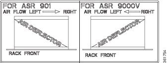

|
||||
|
Step 4 |
If installing from the rear of the 19-inch or 23-inch rack:
|
||||
|
Step 5 |
If installing from the front of the 23-inch rack:
|
||||
|
Step 6 |
Using the Cisco-supplied grounding lug, construct a suitable ground cable of sufficient length. Attach the grounding lug to the rear of the plenum base using two Cisco supplied M4 x 8mm pan-head screws and attach the other end to the grounding source. See the figure Mounting Plenum Assembly in Rack and Attaching Grounding Lug-Cisco ASR 9000v Satellite Shelf Orientation Shown .  |
||||
|
Step 7 |
Install the router in the rack. See the Installing the Cisco ASR 9000v Satellite Shelf and the Mounting the Cisco ASR 901 Router for more information. This figure shows the Cisco ASR 9000v satellite shelf and air plenum kit installed in the rack.
 |
Assembly of Plenum After Mounting in Rack
Summary of Installation
- The rack-mounting brackets are attached to the plenum base.
- The plenum base is installed in the 19-inch rack.
- The air baffles and air deflector are attached to the rack-mounted plenum base. Installation of the air baffles within the rack will require a total of 3 RU clearance to install the air baffles.
- The router is installed in the rack.
Follow these steps to assemble the air plenum kit after the plenum base is mounted in the 19-inch rack when rack/cabinet clearance prevents pre-assembly.
SUMMARY STEPS
- Prepare the components of the air plenum kit for installation. If you are installing a Cisco ASR 9000v satellite shelf in the rack, remove the adjustment plate and M4 x 8mm pan-head screws from the left and right air baffles and discard them, two screws per adjustment plate.
- Attach the rack-mounting brackets to the plenum base using eight Cisco supplied M4 x 8mm pan-head screws, four on each mounting bracket. See this figure.
- Attach the plenum base to the left and right rack rails using customer-supplied rack mounting screws. We recommend using two screws per side. These screws can vary in size and type depending on the rack that you use. Torque the screws to the weight specified for your particular rack. See this figure.
- Attach the left and right air baffles to the rack-mounted plenum base using the four Cisco supplied M4 x 6mm flat-head screws (two per baffle). See the figure Attaching Baffles and Air Deflector to Rack-Mounted Plenum Base—Cisco ASR 9000v Satellite Shelf Orientation Shown.Use the vertical screws to secure the air baffles to the plenum base. If there is no free space available above the plenum base to install the vertical screws use the horizontal screws to secure the air baffles.
- Attach the air deflector to the plenum base using two M4 x 8mm pan-head screws. This figure shows the air-deflector orientation for the Cisco ASR9000v satellite shelf.
- Using the Cisco-supplied grounding lug, construct a suitable ground cable of sufficient length. Attach the grounding lug to the rear of the plenum base using two Cisco supplied M4 x 8mm pan-head screws and attach the other end to the grounding source. See this figure.
- Install the router in the rack. See the Installing the Cisco ASR 9000v Satellite Shelf and the Mounting the Cisco ASR 901 Router for more information. This figure shows the Cisco ASR901 router and air plenum kit installed in the rack.
DETAILED STEPS
|
Step 1 |
Prepare the components of the air plenum kit for installation. If you are installing a Cisco ASR 9000v satellite shelf in the rack, remove the adjustment plate and M4 x 8mm pan-head screws from the left and right air baffles and discard them, two screws per adjustment plate. |
||||||||
|
Step 2 |
Attach the rack-mounting brackets to the plenum base using eight Cisco supplied M4 x 8mm pan-head screws, four on each mounting bracket. See this figure. 
|
||||||||
|
Step 3 |
Attach the plenum base to the left and right rack rails using customer-supplied rack mounting screws. We recommend using two screws per side. These screws can vary in size and type depending on the rack that you use. Torque the screws to the weight specified for your particular rack. See this figure.  |
||||||||
|
Step 4 |
Attach the left and right air baffles to the rack-mounted plenum base using the four Cisco supplied M4 x 6mm flat-head screws (two per baffle). See the figure Attaching Baffles and Air Deflector to Rack-Mounted Plenum Base—Cisco ASR 9000v Satellite Shelf Orientation Shown.Use the vertical screws to secure the air baffles to the plenum base. If there is no free space available above the plenum base to install the vertical screws use the horizontal screws to secure the air baffles. |
||||||||
|
Step 5 |
Attach the air deflector to the plenum base using two M4 x 8mm pan-head screws. This figure shows the air-deflector orientation for the Cisco ASR9000v satellite shelf.
This figure shows the orientation of the air deflector for the Cisco ASR9000v satellite shelf and the Cisco ASR901 Router.
|
||||||||
|
Step 6 |
Using the Cisco-supplied grounding lug, construct a suitable ground cable of sufficient length. Attach the grounding lug to the rear of the plenum base using two Cisco supplied M4 x 8mm pan-head screws and attach the other end to the grounding source. See this figure.  |
||||||||
|
Step 7 |
Install the router in the rack. See the Installing the Cisco ASR 9000v Satellite Shelf and the Mounting the Cisco ASR 901 Router for more information. This figure shows the Cisco ASR901 router and air plenum kit installed in the rack.
 |
 Feedback