Connected Grid Ethernet Switch Module Interface Card Getting Started Guide
Bias-Free Language
The documentation set for this product strives to use bias-free language. For the purposes of this documentation set, bias-free is defined as language that does not imply discrimination based on age, disability, gender, racial identity, ethnic identity, sexual orientation, socioeconomic status, and intersectionality. Exceptions may be present in the documentation due to language that is hardcoded in the user interfaces of the product software, language used based on RFP documentation, or language that is used by a referenced third-party product. Learn more about how Cisco is using Inclusive Language.
- Updated:
- July 11, 2011
Chapter: Installation
Installation
This section describes how to install the switch module in Cisco CGR 2010 routers. The switch module occupies two of four slots on the I/O side of the router. This chapter includes the following topics:
Pre-Installation
Before installing the switch module, verify these guidelines are met:
•![]() Clearance to the I/O-side view is such that the LEDs can be easily read
Clearance to the I/O-side view is such that the LEDs can be easily read
•![]() Cabling is away from sources of electrical noise, such as radios, power lines, and fluorescent lighting fixtures. Make sure that the cabling is away from other devices that might damage the cables.
Cabling is away from sources of electrical noise, such as radios, power lines, and fluorescent lighting fixtures. Make sure that the cabling is away from other devices that might damage the cables.
•![]() Airflow around the switch module and through the vents is unrestricted
Airflow around the switch module and through the vents is unrestricted
•![]() Temperature around the unit does not exceed 140°F (60°C). If the switch module is installed in a closed or multirack assembly, the temperature around it might be higher than normal room temperature.
Temperature around the unit does not exceed 140°F (60°C). If the switch module is installed in a closed or multirack assembly, the temperature around it might be higher than normal room temperature.
•![]() Relative humidity around the switch module does not exceed 95 percent (noncondensing)
Relative humidity around the switch module does not exceed 95 percent (noncondensing)
•![]() Altitude at the installation site is not higher than 10,000 feet
Altitude at the installation site is not higher than 10,000 feet
•![]() For 10/100 and 10/100/1000 fixed ports, cable lengths from the switch module to connected devices are not longer than 328 feet (100 meters)
For 10/100 and 10/100/1000 fixed ports, cable lengths from the switch module to connected devices are not longer than 328 feet (100 meters)
Installation Warning Statements
This section includes the basic installation warning statements. Translations of these warning statements appear in the Regulatory Compliance and Safety Information for the Cisco CGS 2520 Switches and the Regulatory Compliance and Safety Information for Cisco Connected Grid Router 2000 Series Routers documents.
 |
Warning |
|
Warning 140°F (60°C) Statement 1047 |
|
Warning |
Installation
Follow these steps to install the switch module:
Step 1 ![]() Before you install (or remove) the switch module from the host CGR 2010 router, you must power down the router as described in the "Shutting Off Power" section in Chapter 3 of the Cisco Connected Grid Router 2010 Hardware Installation Guide.
Before you install (or remove) the switch module from the host CGR 2010 router, you must power down the router as described in the "Shutting Off Power" section in Chapter 3 of the Cisco Connected Grid Router 2010 Hardware Installation Guide.
Step 2 ![]() Facing the I/O side of the Cisco CGR 2010 router, use a no. 2 Phillips screwdriver to remove the slot divider between the slots where you intend to install the switch module - either slots 0 and 1 or slots 2 and 3 (see Figure 2-1).
Facing the I/O side of the Cisco CGR 2010 router, use a no. 2 Phillips screwdriver to remove the slot divider between the slots where you intend to install the switch module - either slots 0 and 1 or slots 2 and 3 (see Figure 2-1).
a. ![]() Remove the two screws on the slot divider.
Remove the two screws on the slot divider.
b. ![]() Remove the slot divider and set it aside.
Remove the slot divider and set it aside.
Figure 2-1 Removing the Slot Divider From the CGR 2010 Router

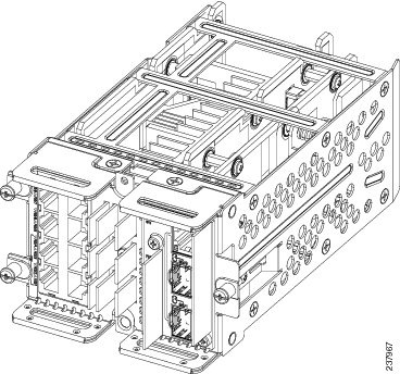
Step 3 ![]() Stand the switch module on end to install it into the Cisco CGR 2010 router slot (see Figure 2-2).
Stand the switch module on end to install it into the Cisco CGR 2010 router slot (see Figure 2-2).
Figure 2-2 Positioning the Switch Module to Install in the Router
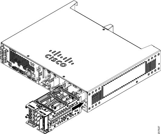
Step 4 ![]() Grasp the handles and carefully slide the module into the card guide, then push with both hands until the module is flush against the router chassis (see Figure 2-3).
Grasp the handles and carefully slide the module into the card guide, then push with both hands until the module is flush against the router chassis (see Figure 2-3).
Figure 2-3 Installing the Switch Module in the CGR 2010 Router
Step 5 ![]() Tighten the screws:
Tighten the screws:
a. ![]() Tighten the lower flathead screw to the bottom center hole.
Tighten the lower flathead screw to the bottom center hole.
b. ![]() Tighten the second panhead screw to the top center hole.
Tighten the second panhead screw to the top center hole.
Step 6 ![]() Tighten the three captive screws on the front of the switch module:
Tighten the three captive screws on the front of the switch module:
a. ![]() Tighten the captive screw on the lower left of the module.
Tighten the captive screw on the lower left of the module.
b. ![]() Tighten the single captive screw on the right side of the module.
Tighten the single captive screw on the right side of the module.
c. ![]() Finally, tighten the captive screw on the upper left of the module.
Finally, tighten the captive screw on the upper left of the module.
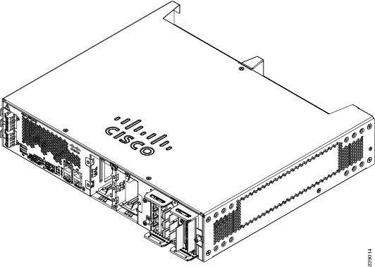
The switch module is now successfully installed in the router (see Figure 2-4).
Figure 2-4 Switch Module Installed in the CGR 2010 Router
Connecting to the Network
•![]() Connecting the Copper Switch Module
Connecting the Copper Switch Module
•![]() Connecting the Fiber Switch Module
Connecting the Fiber Switch Module
Connecting the Copper Switch Module
Follow these steps to connect the switch module's copper model (GRWIC-D-ES-2S-8PC) to the network:
Step 1 ![]() Connect one end of the cable to one of the Fast Ethernet ports on the switch module (see Figure 2-5).
Connect one end of the cable to one of the Fast Ethernet ports on the switch module (see Figure 2-5).
Figure 2-5 Connecting the Copper Model to the Network

Step 2 ![]() Connect the other end of the cable to the RJ-45 connector of the target device.
Connect the other end of the cable to the RJ-45 connector of the target device.
Connecting the Fiber Switch Module
Follow these steps to connect the switch module's fiber model (GRWIC-D-ES-6S) to the network:
Step 1 ![]() Connect one end of the cable to one of the six fiber ports on the fiber model Ethernet switch module (see Figure 2-6).
Connect one end of the cable to one of the six fiber ports on the fiber model Ethernet switch module (see Figure 2-6).
Figure 2-6 Connecting the SFP Fiber Model to the Network

Step 2 ![]() Connect the other end of the cable to the standard LC-type optical connector on the target device.
Connect the other end of the cable to the standard LC-type optical connector on the target device.
Removing the Switch Module

Follow these steps to remove the switch module from the host router:
Step 1 ![]() Power down the CGR 2010 router as described in "Shutting Off Power" in Chapter 3 of the Cisco Connected Grid Router 2010 Hardware Installation Guide.
Power down the CGR 2010 router as described in "Shutting Off Power" in Chapter 3 of the Cisco Connected Grid Router 2010 Hardware Installation Guide.
Step 2 ![]() Remove the three captive screws and the two screws at the top and bottom center of the module.
Remove the three captive screws and the two screws at the top and bottom center of the module.
Step 3 ![]() Grasp the handles firmly with both hands and carefully pull out the switch module.
Grasp the handles firmly with both hands and carefully pull out the switch module.
Step 4 ![]() Power up the router when ready to do so.
Power up the router when ready to do so.
 Feedback