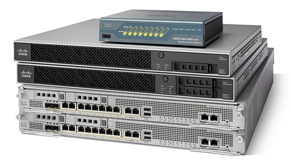
Cisco ASA 5500-X Series Firewalls
| Product Type | Firewalls |
|---|---|
| Status | Available |
| Series Release Date | 03-MAY-2005 |
| Diagram | Visio Stencil (7 MB .zip file) |
|
This product is supported by Cisco, but is no longer being sold.
|
|
- US/Canada 800-553-2447
- Worldwide Support Phone Numbers
- All Tools
 Feedback
 Feedback
-
Top Search Results
Key Information
Customers Also Viewed
Saved Content
-
You can now save documents for easier access and future use. Saved documents for this product will be listed here, or visit the My Saved Content page to view and manage all saved content from across Cisco.com.
Log in to see your Saved Content.
Recent Security Notices
- 02-Dec-2024
- 24-Oct-2024
- 23-Oct-2024
- 23-Oct-2024
- 23-Oct-2024
Document Categories
-
Data Sheets and Product Information
- Cisco ASA Botnet Traffic Filter (PDF - 696 KB)
At-a-Glance
- Cisco ASA 5500 Series Adaptive Security Appliances Data Sheet
- Cisco ASA 5500 and ASA 5500-X Series Next Generation Firewalls for the Internet Edge Data Sheet
- Cisco ASA 5505 Adaptive Security Appliance for Small Office or Branch Locations Data Sheet
- Cisco ASA 5500 Series Advanced Inspection and Prevention Security Services Module and Card
- Cisco ASA 5500 Series Unified Communications Deployments
- Cisco ASA 5500 Series Content Security and Control Security Services Module
Data Sheets
- End-of-Sale and End-of-Life Announcement for the Cisco ASA5508 and ASA5516 Series Security Appliance Subscriptions
- End-of-Sale and End-of-Life Announcement for the Cisco ASA5508 and ASA5516 Series Security Appliance and 5 YR Subscriptions
- End-of-Sale and End-of-Life Announcement for the Cisco ASA5525, ASA5545 & ASA5555 Series 3 YR Subscriptions
- End-of-Sale and End-of-Life Announcement for the Cisco ASA5506 Series Security Appliance 1 YR Subscriptions
- End-of-Sale and End-of-Life Announcement for the Cisco ASA5512 & ASA5515 - 1Yr Subscriptions
- End-of-Sale and End-of-Life Announcement for the Cisco ASA 5585-X with FirePOWER Services Modules -1Yr Subscriptions
- End-of-Sale and End-of-Life Announcement for the Cisco Context Directory Agent (CDA)
- End-of-Sale and End-of-Life Announcement for the Cisco ASA5506 Series Security Appliance with ASA software
- End-of-Sale and End-of-Life Announcement for the Cisco ASA5506 Series Security Appliance 3 YR Subscriptions
- End-of-Sale and End-of-Life Announcement for the Cisco ASA5506 Series Security Appliance 5 YR Subscriptions
- End-of-Sale and End-of-Life Announcement for the Cisco ASA 5505 Adaptive Security Appliance
- End-of-Sale and End-of-Life Announcement for the Cisco ASA 5512-X and ASA 5515-X
- End-of-Sale and End-of-Life Announcement for the Cisco ASA5506W-X WiFi Security Appliances
- End-of-Sale and End-of-Life Announcement for the Cisco ASA 5585-X Adaptive Security Appliance
- End-of-Sale and End-of-Life Announcement for the Cisco ASA CX Context-Aware Security and Cisco Prime Security Manager
End-of-Life and End-of-Sale Notices
-
Security Notices
- Software Lifecycle Support Statement - Next Generation Firewall (NGFW)
- End-of-Sale and End-of-Life Announcement for the Cisco Context Directory Agent (CDA)
Bulletins
-
Applicable to Multiple Models
- Field Notice: FN - 72550 - ASA and Firepower Software: Secure Firewall Appliance Might Traceback And Reload In A High Availability Configuration - Software Upgrade Recommended
- Field Notice: FN - 72439 - ASA and FTD Software: Network Address Translation Might Become Disabled - Software Upgrade Recommended
- Field Notice: FN - 72103 - ASA, FXOS and Firepower Software: QuoVadis Root CA 2 Decommission Might Affect Smart Licensing, Smart Call Home, And Other Functionality - Software Upgrade Recommended
- Field Notice: FN - 72212 - ASA 5500-X - Sustained Burst Of Connection Requests Might Cause Overallocation Of DMA Memory - Workaround Provided
- Field Notice: FN - 70050 - ASA5500-X with FirePOWER Services - FirePOWER Software v5.4.0.9 Can Cause Accelerated Wear of Solid-State Drives - Software Upgrade Recommended
- Field Notice: FN - 64291 - ASA and FTD Software - Security Appliance Might Fail To Pass Traffic After 213 Days Of Uptime - Reboot Required - Software Upgrade Recommended
- Field Notice: FN - 70467 - ASA Software - AnyConnect Connections Might Fail With TCP Connection Limit Exceeded Error - Software Upgrade Recommended
- Field Notice: FN - 63705 - ASA 5500-X Appliances - Default IPS Software Might Not Be Installed - Software Upgrade Recommended
- Field Notice: FN - 63521 - ASA5500-X Appliance - Units shipped without default configuration - Configuration Change Recommended
- Field Notice: FN - 70319 - ASA and FXOS Software - Change in Root Certificate Might Affect Smart Licensing and Smart Call Home Functionality - Software Upgrade Recommended
- Field Notice: FN - 70081 - ASA Software - ASA 5500-X Security Appliance Might Reboot When It Authenticates the AnyConnect Client - Software Upgrade Recommended
- Field Notice: FN - 64315 - ASA Software - Stale VPN Context Entries Cause ASA to Stop Traffic Encryption - Software Upgrade Recommended
- Field Notice: FN - 64227 - ASA Software - Some Commands Might Fail on ASA 5500-X Security Appliances - Software Upgrade Recommended
- Field Notice: FN - 64294 - ISA3000 Software Security Appliance Might Fail To Pass Traffic After 213 Days Of Uptime - Software Upgrade Recommended
-
Cisco ASA 5540 Adaptive Security Appliance
- Field Notice: FN74153 - ASA Software: Secure Firewall Appliance Lina Process Might Traceback And Reload - Software Upgrade Recommended
Field Notices
- Cisco Adaptive Security Appliance WebVPN Login Page Cross-Site Scripting Vulnerability
- Cisco Adaptive Security Appliance and Firepower Threat Defense Software AnyConnect Access Control List Bypass Vulnerabilities
- Cisco Adaptive Security Appliance and Firepower Threat Defense Software Remote Access SSL VPN Authentication Targeted Denial of Service Vulnerability
- Cisco Adaptive Security Appliance and Firepower Threat Defense Software SNMP Denial of Service Vulnerability
- Cisco Firepower Threat Defense Software for Firepower 2100 Series TLS Denial of Service Vulnerability
- Cisco Adaptive Security Appliance and Firepower Threat Defense Software Remote Access SSL VPN Authentication Targeted Denial of Service Vulnerability
- Cisco Adaptive Security Appliance and Firepower Threat Defense Software Dynamic Access Policies Denial of Service Vulnerability
- Cisco Adaptive Security Appliance and Firepower Threat Defense Software Persistent Local Code Execution Vulnerability
- Cisco Adaptive Security Appliance and Firepower Threat Defense Software Remote Access VPN Brute Force Denial of Service Vulnerability
- Cisco Adaptive Security Appliance and Firepower Threat Defense Software SSL VPN Memory Management Denial of Service Vulnerability
- Cisco Adaptive Security Virtual Appliance and Secure Firewall Threat Defense Virtual SSL VPN Denial of Service Vulnerability
- Cisco Adaptive Security Appliance and Firepower Threat Defense Software Remote Access VPN Denial of Service Vulnerability
- Cisco Adaptive Security Appliance and Firepower Threat Defense Software VPN Web Client Services Cross-Site Scripting Vulnerabilities
- Cisco Adaptive Security Appliance Software SSH Server Resource Denial of Service Vulnerability
- Cisco Adaptive Security Appliance and Firepower Threat Defense Software NSG Access Control List Bypass Vulnerability
Security Advisories, Responses and Notices
-
Release and Compatibility
- Cisco Secure Firewall ASA Compatibility
- Cisco Secure Firewall Threat Defense Compatibility Guide
- Supported VPN Platforms, Cisco Secure Firewall ASA Series
- Cisco Firepower Classic Device Compatibility Guide
- Cisco Secure Firewall Migration Tool Compatibility Guide
Compatibility Information
- Cisco Secure Firewall Management Center New Features by Release
- Cisco Secure Firewall Threat Defense/Firepower Hotfix Release Notes
- Cisco Secure Firewall Device Manager New Features by Release
- Cisco ASA New Features by Release
- Firepower Hotfix Release Notes
- Cisco Firepower Release Notes, Version 6.2.3.1, 6.2.3.2, 6.2.3.3, 6.2.3.4, 6.2.3.5, 6.2.3.6, 6.2.3.7, 6.2.3.9, 6.2.3.10, 6.2.3.11, 6.2.3.12, 6.2.3.13, 6.2.3.14, 6.2.3.15, 6.2.3.16, and 6.2.3.17
- Cisco Firepower Release Notes, Version 6.2.3
- Release Notes for the Cisco ASA Series, 9.14(x)
- Cisco Firepower Release Notes, Version 6.5.0.1
- Firepower Release Notes, Version 6.3.0.1 and 6.3.0.2
- Firepower 마이그레이션 툴 릴리즈 노트 (PDF)
- Firepower 마이그레이션 툴 릴리즈 노트 (PDF)
- Release Notes for the Cisco ASA Device Package Software, Version 1.3(12) for ACI
- Release Notes for the Cisco ASA Device Package Software, Version 1.2(12) for ACI
- Release Notes for the Cisco ASA Series, 9.9(x)
Release Notes
-
Reference
-
ASA Command Reference
-
Firepower Threat Defense Command Reference
-
Translations
Command References
- Navigating the Cisco Secure Firewall Threat Defense Documentation
- Navigating the Cisco Secure Firewall ASA Series Documentation
- Navigating the Cisco Secure Firewall Migration Tool Documentation
- Welcome to the Cisco ASA 5500-X Series
- Welcome to the Cisco ASA 5505
- Welcome to the Cisco ASA 5585-X
Documentation Roadmaps
-
Feature Licenses
-
Open Source Licenses
- Open Source Licensing Information for Releases 6.4 and Later
- Open Source Used In Cisco Firepower Version 6.3 (PDF)
- Open Source Used In Cisco Firepower Version 6.2.3 (PDF)
- Open Source Used In Cisco Firepower Version 6.2.2 (PDF)
- Open Source Used In Firepower System Version 6.2 (PDF)
- Open Source Used In Firepower System Version 6.1 (PDF)
- Open Source Used In FireSIGHT System Version 5.4.1.x (PDF)
- Open Source Licensing Information (PDF)
- Open Source Used In Context Directory Agent 1.0 (PDF)
Licensing Information
- Cisco Secure Firewall Reference Guide
Technical References
-
-
Design
-
Install and Upgrade
- Migrating ASA with FirePOWER Services (FPS) Firewall to Secure Firewall Threat Defense with the Migration Tool
- Migrating Fortinet Firewall to Secure Firewall Threat Defense with the Migration Tool
- Migrating Palo Alto Networks Firewall to Secure Firewall Threat Defense with the Migration Tool
- Migrating Check Point Firewall to Secure Firewall Threat Defense with the Migration Tool
- Migrating ASA to Firepower Threat Defense with the Firepower Migration Tool
- Cisco ASA and Firepower Threat Defense Reimage Guide
- Migrating Firewalls with the Firewall Migration Tool in Cisco Security Cloud Control
- Cisco ASA Upgrade Guide
- Cisco Secure Firewall ASA to Threat Defense Feature Mapping
- Migrating from the Cisco ASA 5500 to the Cisco Adaptive Security Virtual Appliance
- Secure Firewall Management Center and Threat Defense Management Network Administration
- Cisco Firepower Management Center Remediation Module for ACI, Version 1.0.1_7 Quick Start Guide (PDF)
- Cisco Firepower Management Center Remediation Module for ACI, Version 1.0.2 Quick Start Guide (PDF)
- Migrating ASA to Firepower Threat Defense Using Cisco Defense Orchestrator
- Cisco ASA REST API Quick Start Guide
Install and Upgrade Guides
-
Configuration
- Configure ASA: SSL Digital Certificate Installation and Renewal
- Configure AnyConnect Client Access to Local LAN
- Configure the ASA for Redundant or Backup ISP Links
- Configure VPN Filters on ASA
- Disable SSH Server CBC Mode Ciphers on ASA
- Configure ASA VPN Posture with CSD, DAP and AnyConnect 4.0
- Configure ASA Border Gateway Protocol
- Configure a Site-to-Site VPN Tunnel with ASA and Strongswan
- Configure Network Address Translation and ACLs on an ASA Firewall
- Configure AnyConnect VPN Client U-turn Traffic on ASA 9.X
- Use LDAP Attribute Maps Configuration Example
- Configure Adaptive Security Appliance (ASA) Syslog
- Configure FTD from ASA Configuration File with Firepower Migration Tool
- ASA: Smart Tunnel using ASDM Configuration Example
- ASA with CX/FirePower Module and CWS Connector Configuration Example
Configuration Examples and TechNotes
- Cisco Firepower Threat Defense Configuration Guide for Firepower Device Manager, Version 6.4.0
- Firepower Management Center Configuration Guide, Version 6.0.1
- Cisco Firepower Threat Defense Configuration Guide for Firepower Device Manager, Version 6.6.0
- Cisco Firepower Threat Defense Configuration Guide for Firepower Device Manager, Version 6.5.0
- Firepower Management Center Configuration Guide, Version 6.5
- Cisco Secure Firewall ASA HTTP Interface for Automation
- Cisco ASA NetFlow Implementation Guide
- Firepower Management Center Configuration Guide, Version 6.6
- Cisco Firepower Threat Defense Hardening Guide, Version 7.0
- Cisco Secure Firewall Threat Defense Hardening Guide, Version 7.2
- Firepower Management Center Configuration Guide, Version 6.4
- Firepower Management Center Configuration Guide, Version 6.2.3
- About the ASA REST API
- Cisco ASA Legacy Feature Guide
- Cisco ASA Botnet Traffic Filter Guide
Configuration Guides
- Cisco Secure Firewall Threat Defense REST API Guide
Programming Guides
-
Maintain and Operate
- Optimize AnyConnect Split Tunnel for Microsoft Office 365/Webex
- EEM Examples for Different VPN Scenarios on ASA
Maintain and Operate TechNotes
-
Troubleshooting
-
Syslog and Error Messages
Error and System Messages
- What does the IPS message “IPS SSP application reloading IPS" mean?
- ASA FAQ: How do you interpret the syslogs generated by the ASA when it builds or tears down connections?
- ASA FAQ: What happens after failover if dynamic routes are synchronized?
- ASA - When and why to use the write standby command?
- Why Does the ASA have xlate Entries with Idle Values Longer than the Configured Timeouts?
- ASA 5500 Series Adaptive Security Appliance FAQ
Support FAQ
- Monitor and Troubleshoot ASA Performance Issues
- Use ASA IKEv2 Debugs for Site-to-Site VPN with PSKs
- IPsec Troubleshooting: Understanding and Using debug Commands
- Configure Site-to-Site IKEv2 Tunnel between ASA and Router
- Understand ASA High Availability MAC Table Synchronization on Transparent Mode with HSRP Routers
- Configure ASA Version 9 Port Forwarding with NAT
- Fix AnyConnect Cryptographic Algorithms Error with FIPS Enabled
- AnyConnect VPN Client Troubleshooting Guide - Common Problems
- CWS on ASA Traffic to Internal Servers Blocked
- ASA VPN Load Balancing Director Election Process
- Cut-Through and Direct ASA Authentication Configuration Example
- ASA 8.3 Issue: MSS Exceeded - HTTP Clients Cannot Browse to Some Websites
- MPTCP and Product Support Overview
- U.S. Daylight Saving Time (DST) Changes for 2007 to Present
- Troubleshoot AnyConnect VPN Phone - IP Phones, ASA, and CUCM
Troubleshooting TechNotes
-
-
Literature
- Oxford University Hospital Customer Case Study (PDF - 425 KB)
- Wireless quality gives Messe Frankfurt powerful tools with multiple benefits for events (PDF - 182 KB)
- Frankfurt Airport transforms workplace efficiency with WiFi next generation (PDF - 253 KB)
Case Studies
-
Log in to see available downloads.
-
-
Unless specified, documentation for the Cisco ASA 5500-X Series Firewalls is applicable to all models.
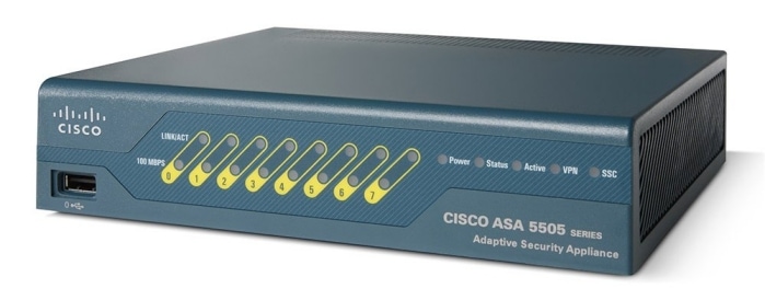
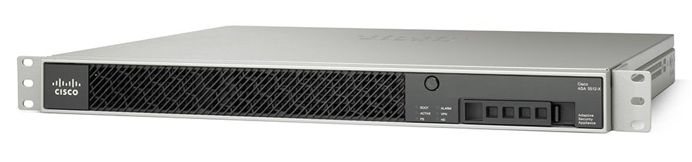
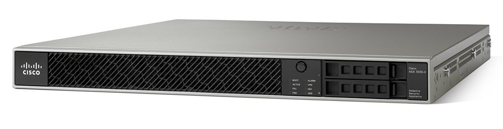
This series is supported by Cisco, but is no longer sold, and some models have been retired:
- Cisco ASA 5525-X Adaptive Security Appliance
- Cisco ASA 5525-X Adaptive Security Appliance w/no Payload Encryption
- Cisco ASA 5545-X Adaptive Security Appliance
- Cisco ASA 5545-X Adaptive Security Appliance w/no Payload Encryption
- Cisco ASA 5555-X Adaptive Security Appliance
- Cisco ASA 5555-X Adaptive Security Appliance w/no Payload Encryption
Retired Models:
- Cisco ASA 5505 Adaptive Security Appliance - End-of-Support Date: 31-Aug-2022
- Cisco ASA 5512-X Adaptive Security Appliance - End-of-Support Date: 31-Aug-2022
- Cisco ASA 5512-X Adaptive Security Appliance w/no Payload Encryption - End-of-Support Date: 31-Aug-2022
- Cisco ASA 5515-X Adaptive Security Appliance - End-of-Support Date: 31-Aug-2022
- Cisco ASA 5515-X Adaptive Security Appliance w/no Payload Encryption - End-of-Support Date: 31-Aug-2022
- Cisco ASA for Nexus 1000V Series Switch - End-of-Support Date: 11-Dec-2023
