Cisco ASA IPS Module Quick Start Guide
Available Languages
Table Of Contents
Information About the IPS Module on the ASA
Connecting the ASA IPS Management Interface
ASA 5510, ASA 5520, ASA 5540, ASA 5580, ASA 5585-X (Physical Module)
ASA 5512-X through ASA 5555-X (Software Module)
Launching the Adaptive Security Device Manager (ASDM) on the ASA
(ASA 5512-X through ASA 5555-X) License Requirements
Configuring Basic IPS Module Network Settings
(ASA 5512-X through ASA 5555-X; May Be Required) Booting the Software Module
Configuring the IPS Security Policy
Redirecting Traffic to the IPS Module
Quick Start Guide
Cisco ASA IPS Module
Revised: October 11, 20121 Information About the IPS Module on the ASA
The IPS module might be a physical module or a software module, depending on your ASA model. For ASA model software and hardware compatibility with the IPS module, see the Cisco ASA Compatibility at http://www.cisco.com/en/US/docs/security/asa/compatibility/asamatrx.html.
The IPS module runs advanced IPS software that provides proactive, full-featured intrusion prevention services to stop malicious traffic, including worms and network viruses, before they can affect your network.
The IPS module runs a separate application from the ASA. The IPS module might include an external management interface so you can connect to the IPS module directly; if it does not have a management interface, you can connect to the IPS module through the ASA interface. Any other interfaces on the IPS module, if available for your model, are used for ASA traffic only.
Traffic goes through the firewall checks before being forwarded to the IPS module. When you identify traffic for IPS inspection on the ASA, traffic flows through the ASA and the IPS module as follows. Note: This example is for "inline mode." See the ASA configuration guide for information about "promiscuous mode," where the ASA only sends a copy of the traffic to the IPS module.
1.
Traffic enters the ASA.
2.
Incoming VPN traffic is decrypted.
3.
Firewall policies are applied.
4.
Traffic is sent to the IPS module.
5.
The IPS module applies its security policy to the traffic, and takes appropriate actions.
6.
Valid traffic is sent back to the ASA; the IPS module might block some traffic according to its security policy, and that traffic is not passed on.
7.
Outgoing VPN traffic is encrypted.
8.
Traffic exits the ASA.
The following figure shows the traffic flow when running the IPS module in inline mode. In this example, the IPS module automatically blocks traffic that it identified as an attack. All other traffic is forwarded through the ASA.

2 Connecting the ASA IPS Management Interface
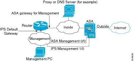
In addition to providing management access to the IPS module, the IPS management interface needs access to an HTTP proxy server or a DNS server and the Internet so it can download global correlation, signature updates, and license requests. This section describes recommended network configurations. Your network may differ.
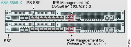
ASA 5510, ASA 5520, ASA 5540, ASA 5580, ASA 5585-X (Physical Module)
The IPS module includes a separate management interface from the ASA.

If you have an inside router
If you have an inside router, you can route between the management network, which can include both the ASA Management 0/0 and IPS Management 1/0 interfaces, and the ASA inside network. Be sure to also add a route on the ASA to reach the Management network through the inside router.

If you do not have an inside router
If you have only one inside network, then you cannot also have a separate management network, which would require an inside router to route between the networks. In this case, you can manage the ASA from the inside interface instead of the Management 0/0 interface. Because the IPS module is a separate device from the ASA, you can configure the IPS Management 1/0 address to be on the same network as the inside interface.

ASA 5512-X through ASA 5555-X (Software Module)
These models run the IPS module as a software module, and the IPS management interface shares the Management 0/0 interface with the ASA.

If you have an inside router
If you have an inside router, you can route between the Management 0/0 network, which includes both the ASA and IPS management IP addresses, and the inside network. Be sure to also add a route on the ASA to reach the Management network through the inside router.

If you do not have an inside router
If you have only one inside network, then you cannot also have a separate management network. In this case, you can manage the ASA from the inside interface instead of the Management 0/0 interface. If you remove the ASA-configured name from the Management 0/0 interface, you can still configure the IPS IP address for that interface. Because the IPS module is essentially a separate device from the ASA, you can configure the IPS management address to be on the same network as the inside interface.


Note
You must remove the ASA-configured name for Management 0/0; if it is configured on the ASA, then the IPS address must be on the same network as the ASA, and that excludes any networks already configured on other ASA interfaces. If the name is not configured, then the IPS address can be on any network, for example, the ASA inside network.
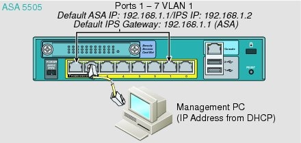
ASA 5505
The ASA 5505 does not have a dedicated management interface. You must use an ASA VLAN to access an internal management IP address over the backplane. Connect the management PC to one of the following ports: Ethernet 0/1 through 0/7, which are assigned to VLAN 1.

3 Launching the Adaptive Security Device Manager (ASDM) on the ASA
The default ASA configuration lets you connect to the default management IP address (192.168.1.1). Depending on your network, you might need to change the ASA management IP address, or even configure additional ASA interfaces for ASDM access (see the "Connecting the ASA IPS Management Interface" section). For the ASA 5512-X through ASA 5555-X, if you do not have a separate management network (see the "If you do not have an inside router" section), you need to configure an inside interface for management, and you need to remove the name from the Management 0/0 interface. To change interface and management settings, see the ASA configuration guide.
Step 1
On the management PC, launch a web browser.
Step 2
In the Address field, enter the following URL: https://ASA_IP_address/admin. The default ASA management IP address is 192.168.1.1.
Step 3
Click Run ASDM to run the Java Web Start application. Alternatively, you can download the ASDM-IDM Launcher. See the ASA configuration guide for more information.
Step 4
Accept any certificates according to the dialog boxes that appear. The Cisco ASDM-IDM Launcher dialog box appears.
Step 5
Leave the username and password fields empty, and click OK. The main ASDM window appears.
4 (ASA 5512-X through ASA 5555-X) License Requirements
For the ASA 5512-X through the ASA 5555-X, the ASA requires the IPS Module license. For a failover pair, each unit requires this license. To view your current licenses, in ASDM choose Home > Device Dashboard > Device Information > Device License. For more information about ASA licenses, see the licensing chapter in the configuration guide.
5 Configuring Basic IPS Module Network Settings
ASA 5510 and Higher
Use the ASDM Startup Wizard to configure basic IPS network settings. These settings are saved to the IPS configuration, not the ASA configuration.
Step 1
Choose Wizards > Startup Wizard.
Step 2
Click Next to advance through the initial screens until you reach the IPS Basic Configuration screen.

Note
(ASA 5512-X through ASA 5555-X) If you do not see the IPS Basic Configuration screen in your wizard, then the IPS module is not running. See the "(ASA 5512-X through ASA 5555-X; May Be Required) Booting the Software Module" section, and then repeat this procedure after you install the module.
Step 3
In the Network Settings area, configure the following:
–
IP Address—The management IP address. By default, the address is 192.168.1.2, on the same network as the default ASA management IP address. See the "Connecting the ASA IPS Management Interface" section to understand the requirements for your network.
–
Subnet Mask—The subnet mask for the management IP address.
–
Gateway—The IP address of the next hop router. See the "Connecting the ASA IPS Management Interface" section to understand the requirements for your network. The default setting of the ASA management IP address will not work.
–
HTTP Proxy Server—(Optional) The HTTP proxy server address. You can use a proxy server to download global correlation updates and other information instead of downloading over the Internet.
–
HTTP Proxy Port—(Optional) The HTTP proxy server port.
–
DNS Primary—(Optional) The primary DNS server address. You need a DNS server to communicate with the update server over the Internet.
Step 4
In the Management Access List area, enter the following:
a.
Enter the IP address for the management host network.
b.
Choose the subnet mask from the drop-down list.
c.
Click Add to add these settings to the Allowed Hosts/Networks list.
Step 5
In the Cisco Account Password area, set the password for the username cisco and confirm it. The username cisco and this password are used for Telnet sessions from hosts specified by the management access list and when accessing the IPS module from ASDM (Configuration > IPS). By default, the password is cisco.
Step 6
In the Network Participation area, for participating in SensorBase data sharing, click Full, Partial, or Off.
Step 7
Click Next to advance through the remaining screens, and complete the wizard.
ASA 5505
Use ASDM to configure basic IPS network configuration. These settings are saved to the IPS configuration, not the ASA configuration.
Step 1
Choose Configuration > Device Setup > SSC Setup.
Step 2
In the Management Interface area, set the following:
a.
Choose the Interface VLAN from the drop-down list. This setting lets you manage the ASA IPS module using this VLAN. By default, the management VLAN is VLAN 1 (the inside interface).
b.
Enter the IPS management IP address. Make sure this address is on the same subnet as the ASA VLAN IP address. For example, if you assigned 10.1.1.1 to the VLAN for the ASA, then assign another address on that network, such as 10.1.1.2, for the IPS management address. By default, the address is 192.168.1.2.
c.
Choose the subnet mask from the drop-down list.
d.
Enter the default gateway IP address. Set the gateway to be the ASA IP address for the management VLAN. By default, this IP address is 192.168.1.1.
Step 3
In the Management Access List area, enter the following:
a.
Enter the IP address for the management host network, typically the same network as the management IP address.
b.
Choose the subnet mask from the drop-down list.
c.
Click Add to add these settings to the Allowed Hosts/Networks list.
Step 4
In the IPS Password area, do the following:
a.
Enter the current password. The default password is cisco.
b.
Enter the new password, and confirm the change.
Step 5
Click Apply to save the settings to the running configuration.
Step 6
To launch the IPS Startup Wizard, click the Configure the IPS SSC module link.
6 (ASA 5512-X through ASA 5555-X; May Be Required) Booting the Software Module
Your ASA typically ships with IPS module software present on Disk0. If the module is not running, or if you are adding the IPS module to an existing ASA, you must boot the module software.
Step 1
Do one of the following:
•
New ASA with IPS pre-installed—View the IPS module software filename in flash memory. Choose Tools > File Management.
For example, look for a filename like IPS-SSP_5512-K9-sys-1.1-a-7.1-4-E4.aip. Note the filename; you will need this filename later in the procedure.
•
Existing ASA with new IPS installation—Download the IPS software from Cisco.com to your computer. If you have a Cisco.com login, you can obtain the software from the following website:
http://www.cisco.com/cisco/software/navigator.html?mdfid=282164240
Choose Tools > File Management, then choose File Transfer > Between Local PC and Flash to upload the new image to disk0. Note the filename; you will need this filename later in the procedure.
Step 2
Choose Tools > Command Line Interface.
Step 3
To set the IPS module software location in disk0, enter the following command and then click Send:
sw-module module ips recover configure image disk0:file_pathFor example, using the filename in the example in Step 1, enter:
sw-module module ips recover configure image
disk0:IPS-SSP_5512-K9-sys-1.1-a-7.1-4-E4.aip
Step 4
To boot the IPS module software, enter the following command and then click Send:
sw-module module ips recover bootStep 5
To check the progress of the image transfer and module restart process, enter the following command and then click Send:
show module ips detailsThe Status field in the output indicates the operational status of the module. A module operating normally shows a status of "Up." While the ASA transfers an application image to the module, the Status field in the output reads "Recover." When the ASA completes the image transfer and restarts the module, the newly transferred image is running.
7 Configuring the IPS Security Policy
Step 1
To access the IPS Device Manager (IDM) from ASDM, click Configuration > IPS.

Step 2
Enter the IP address you set in "Configuring Basic IPS Module Network Settings" section, as well as the port; the default address and port is 192.168.1.2:443.
Step 3
Enter the username cisco and the password you set in "Configuring Basic IPS Module Network Settings" section; the default password is cisco.
Step 4
To save the login information on your local PC, check the Save IPS login information on local host check box.
Step 5
Click Continue. The Startup Wizard pane appears.

Step 6
Click Launch Startup Wizard. Complete the screens as prompted. For more information, see the IDM online help.

8 Redirecting Traffic to the IPS Module
All traffic sent over the backplane to the IPS module has the IPS security policy applied. Perform the following steps to determine what traffic to send to the IPS module:
Step 1
In ASDM, choose Configuration > Firewall > Service Policy Rules.

Step 2
Choose Add > Add Service Policy Rule. The Add Service Policy Rule Wizard - Service Policy dialog box appears.
Step 3
Complete the Service Policy dialog box, and then the Traffic Classification Criteria dialog box as desired. See the ASDM online help for more information about these screens.
Step 4
Click Next to show the Add Service Policy Rule Wizard - Rule Actions dialog box.
Step 5
Click the Intrusion Prevention tab.

Step 6
Check the Enable IPS for this traffic flow check box.
Step 7
In the Mode area, click Inline Mode or Promiscuous Mode. Inline mode places the IPS module directly in the traffic flow. No traffic that you identified for IPS inspection can continue through the ASA without first passing through, and being inspected by, the IPS module. Promiscuous mode sends a duplicate stream of traffic to the IPS module. This mode is less secure, but has little impact on traffic throughput.
Step 8
In the If IPS Card Fails area, click Permit traffic or Close traffic. The Close traffic option sets the ASA to block all traffic if the IPS module is unavailable. The Permit traffic option sets the ASA to allow all traffic through, uninspected, if the IPS module is unavailable. For information about the IPS Sensor Selection area, see the ASDM online help.
Step 9
Click OK and then Apply.
Step 10
Repeat this procedure to configure additional traffic flows as desired.
9 Where to Go Next
•
(Optional) Configure advanced IPS options, including virtual sensors. See the IDM online help or the documentation roadmap for your version:
http://www.cisco.com/en/US/products/hw/vpndevc/ps4077/products_documentation_roadmaps_list.html
•
(Optional) Configure virtual sensors on the ASA. See the online help or the IPS chapter in the configuration guide for your ASA version:
Contact Cisco
- Open a Support Case

- (Requires a Cisco Service Contract)
 Feedback