How to Configure the Device in Firepower Device Manager
After you complete the setup wizard, you should have a functioning device with a few basic policies in place:
-
(Except for ASA 5506-X and.) An outside and an inside interface. No other data interfaces are configured.
-
(ASA 5506-X, only.) An outside interface, and an inside bridge group that includes all other data interfaces.
-
Security zones for the inside and outside interfaces.
-
An access rule trusting all inside to outside traffic.
-
A interface NAT rule that translates all inside to outside traffic to unique ports on the IP address of the outside interface.
-
A DHCP server running on the inside interface or bridge group.
The following steps provide an overview of additional features you might want to configure. Please click the help button (?) on a page to get detailed information about each step.
Procedure
| Step 1 |
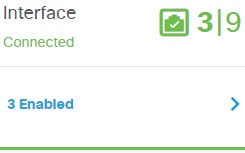
Choose Device, then click View Configuration in the Smart License group. Click Enable for each of the optional licenses you want to use: Threat, Malware, URL. Read the explanation of each license if you are unsure of whether you need it. If you have not registered, you can do so from this page. Click Request Register and follow the instructions. Please register before the evaluation license expires. For example, an enabled Threat license should look like the following: 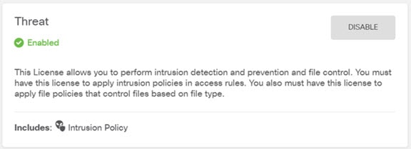 |
| Step 2 |
If you wired other interfaces, choose Device, then click View Configuration in the Interfaces group and configure each wired interface. Because the ASA 5506-X and comes pre-configured with a bridge group containing all non-outside data interfaces, there is no need to configure these interfaces. However, if you want to break apart the bridge group, you can edit it to remove the interfaces you want to treat separately. Then you can configure those interfaces as hosting separate networks. For other models, you can create a bridge group for the other interfaces, or configure separate networks, or some combination of both. Click the edit
icon ( The following example configures an interface to be used as a “demilitarized zone” (DMZ), where you place publically-accessible assets such as your web server. Click Save when you are finished. 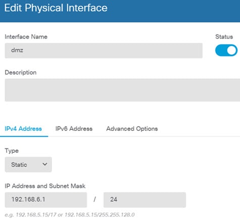 |
| Step 3 |
If you configured new interfaces, choose Objects, then select Security Zones from the table of contents. Edit or create new zones as appropriate. Each interface must belong to a zone, because you configure policies based on security zones, not interfaces. You cannot put the interfaces in zones when configuring them, so you must always edit the zone objects after creating new interfaces or changing the purpose of existing interfaces. The following example shows how to create a new dmz-zone for the dmz interface. 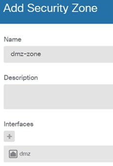 |
| Step 4 |
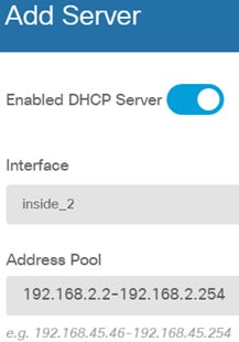
If you want internal clients to use DHCP to obtain an IP address from the device, choose Device, then . Select the DHCP Servers tab. There is already a DHCP server configured for the inside interface, but you can edit the address pool or even delete it. If you configured other inside interfaces, it is very typical to set up a DHCP server on those interfaces. Click + to configure the server and address pool for each inside interface. You can also fine-tune the WINS and DNS list supplied to clients on the Configuration tab. The following example shows how to set up a DHCP server on the inside2 interface with the address pool 192.168.4.50-192.168.4.240. 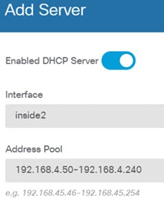 |
| Step 5 |
Choose Device, then click View Configuration (or Create First Static Route) in the Routing group and configure a default route. The default route normally points to the upstream or ISP router that resides off the outside interface. A default IPv4 route is for any-ipv4 (0.0.0.0/0), whereas a default IPv6 route is for any-ipv6 (::0/0). Create routes for each IP version you use. If you use DHCP to obtain an address for the outside interface, you might already have the default routes that you need. The routes you define on this page are for the data interfaces only. They do not impact the management interface. Set the management gateway on . The following example shows a default route for IPv4. In this example, isp-gateway is a network object that identifies the IP address of the ISP gateway (you must obtain the address from your ISP). You can create this object by clicking Create New Network at the bottom of the Gateway drop-down list. 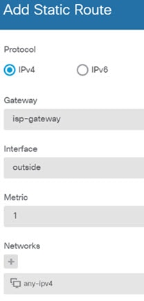 |
| Step 6 |
Choose Policies and configure the security policies for the network. The device setup wizard enables traffic flow between the inside-zone and outside-zone, and interface NAT for all interfaces when going to the outside interface. Even if you configure new interfaces, if you add them to the inside-zone object, the access control rule automatically applies to them. However, if you have multiple inside interfaces, you need an access control rule to allow traffic flow from inside-zone to inside-zone. If you add other security zones, you need rules to allow traffic to and from those zones. These would be your minimum changes. In addition, you can configure other policies to provide additional services, and fine-tune NAT and access rules to get the results that your organization requires. You can configure the following policies:
The following example shows how to allow traffic between the inside-zone and dmz-zone in the access control policy. In this example, no options are set on any of the other tabs except for Logging, where At End of Connection is selected.  |
| Step 7 |
Commit your changes. |










 Feedback