Migrating Policy-Based VPN to Route-Based VPN Using Cisco Secure Firewall Management Center
Introduction
This document guides you to migrate a policy-based VPN to a route-based VPN using the VPN wizard of the Cisco Secure Firewall Management Center.
Organizations relying on policy-based VPNs face significant challenges in managing and scaling their network infrastructure. Policy-based VPNs require complex access lists and precise ordering, making them prone to configuration errors and difficult to manage, especially as the network grows. Also, they lack support for dynamic routing protocols. Addition of new spokes requires manual VPN configuration updates on the hub. These drawbacks not only increase the administrative burden but also limit the scalability and flexibility of the network, making it less efficient and error-prone.
Migrating to route-based VPNs using Virtual Tunnel Interfaces (VTIs) simplifies configuration, management, improves network reliability, scalability, and manageability, meeting growing business needs.
About Route-Based VPN
Route-based VPN uses routable logical interfaces called Virtual Tunnel Interfaces (VTIs) to establish a VPN tunnel between peers. You can use these interfaces like other interfaces, and apply static and dynamic routing policies to them. You can create a routed security zone, add VTI interfaces to it, and define access control rules for the decrypted traffic over the VTI tunnel. The threat defense device encrypts or decrypts the traffic to or from the tunnel interface and forwards it according to the routing policy. You can configure route-based VPN with static VTI (SVTI) or dynamic VTI (DVTI) using the site-to-site VPN wizard.
Benefits of Route-Based VPN
The benefits of using a route-based VPN in a hub and spoke topology are:
-
Streamlined Setup: VTI offers a simplified approach to VPN configuration, removing the complexity of traditional crypto maps and access lists.
-
Simplified Management: VTI simplifies the management of peer configurations for large enterprise hub and spoke deployments. A single dynamic VTI configuration on the hub can support multiple spokes with static VTIs.
-
Adaptive Routing: VTI accommodates dynamic routing protocols such as BGP, EIGRP, and OSPF, facilitating the automatic update of routes between VPN endpoints in response to changing network conditions.
-
Dual ISP Redundancy: VTI enables the creation of secondary backup tunnels, enhancing connectivity reliability.
-
Load balancing: VTI allows for the even distribution of VPN traffic through ECMP routing.
Recommendations for Migrating Policy-Based VPN to Route-Based VPN
Before you start the migration from policy-based VPN to route-based VPN using the management center, you must:
-
Select a routing protocol for the route-based VPN according to your network requirements.
-
Select an IP address for the spoke’s static VTI interface.
If you have multiple spokes, we recommend that you allocate a subnet for the VTI interfaces.
Note the following recommendations for configuring a spoke static VTI IP address:
-
Use an IP address in the range: 169.254.x.x/16.
-
Do not use the IP address range reserved for the Threat Defense devices: 169.254.1.x/24.
-
Use an IP address with /30 as the netmask for point-to-point tunnels using static VTI, for example, use 169.254.2.1/30.
-
Use Case 1: Migrating Peer to Peer Policy-Based VPN to Peer to Peer Route-Based VPN
Scenario
A medium-sized enterprise currently operates a network with two Threat Defense devices with a policy-based VPN. These devices are managed by a Management Center Version 7.4.1. Recognizing the advantages of route-based VPNs, such as improved scalability and simplified network management, the network administrator plans to migrate to a route-based VPN. To facilitate this transition, the administrator will utilize the Management Center's VPN wizard, which is designed to streamline the configuration process and ensure a seamless migration. This migration aims to enhance the network's robustness and flexibility, supporting the organization's growth and evolving connectivity needs.
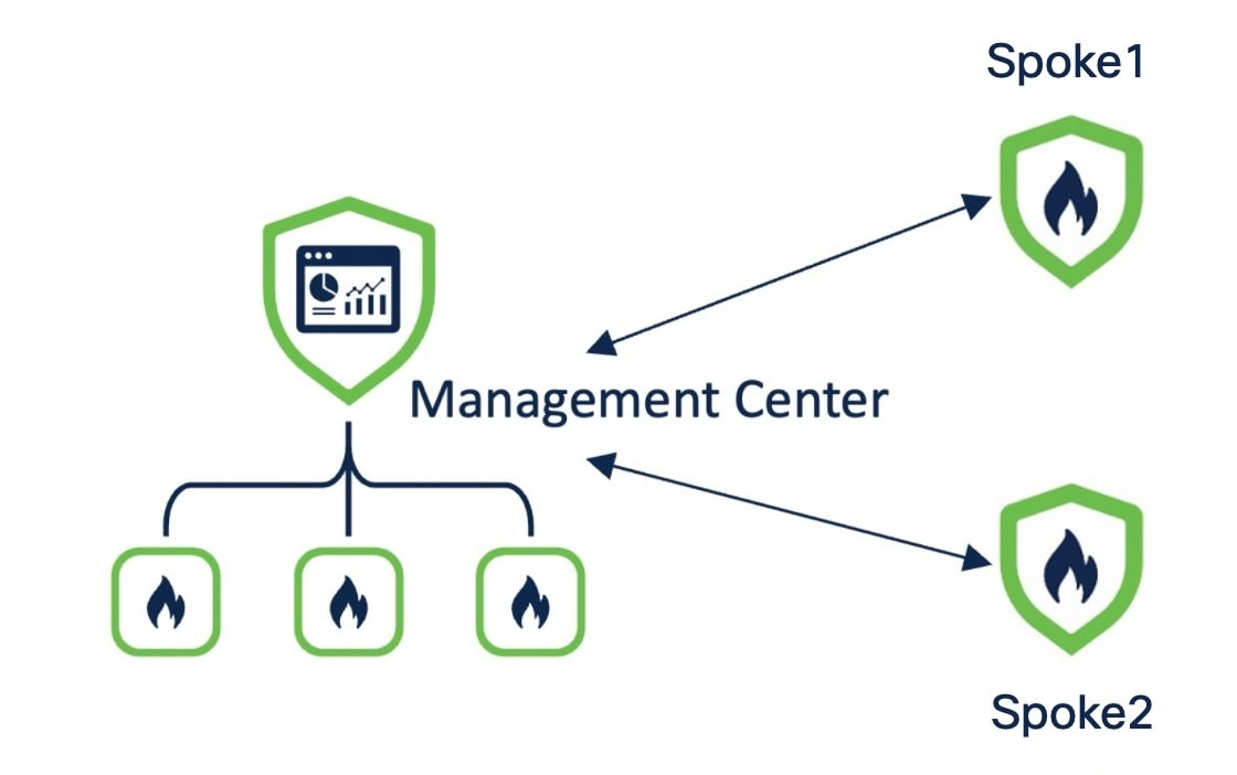
The policy-based VPN topology has the following parameters:
|
Threat Defense Device |
Protected Network |
VPN Interface |
|---|---|---|
|
Spoke1 |
198.51.100.16/28 |
209.165.201.1 |
|
Spoke 2 |
198.51.100.32/28 |
209.165.201.2 |
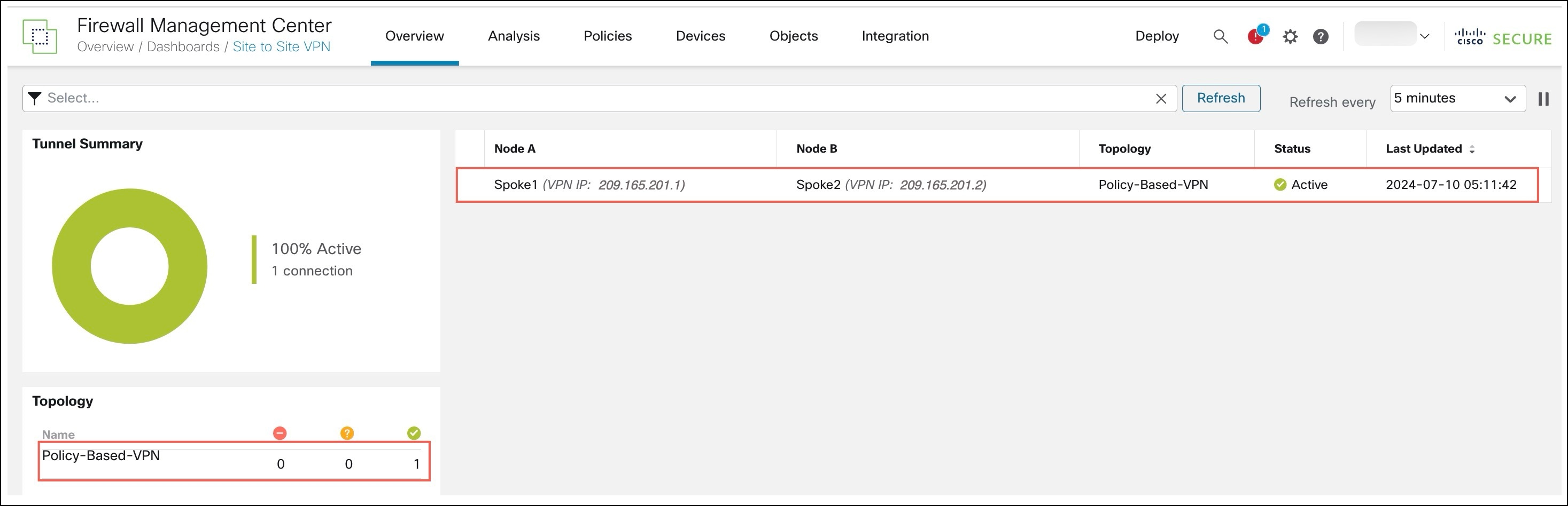
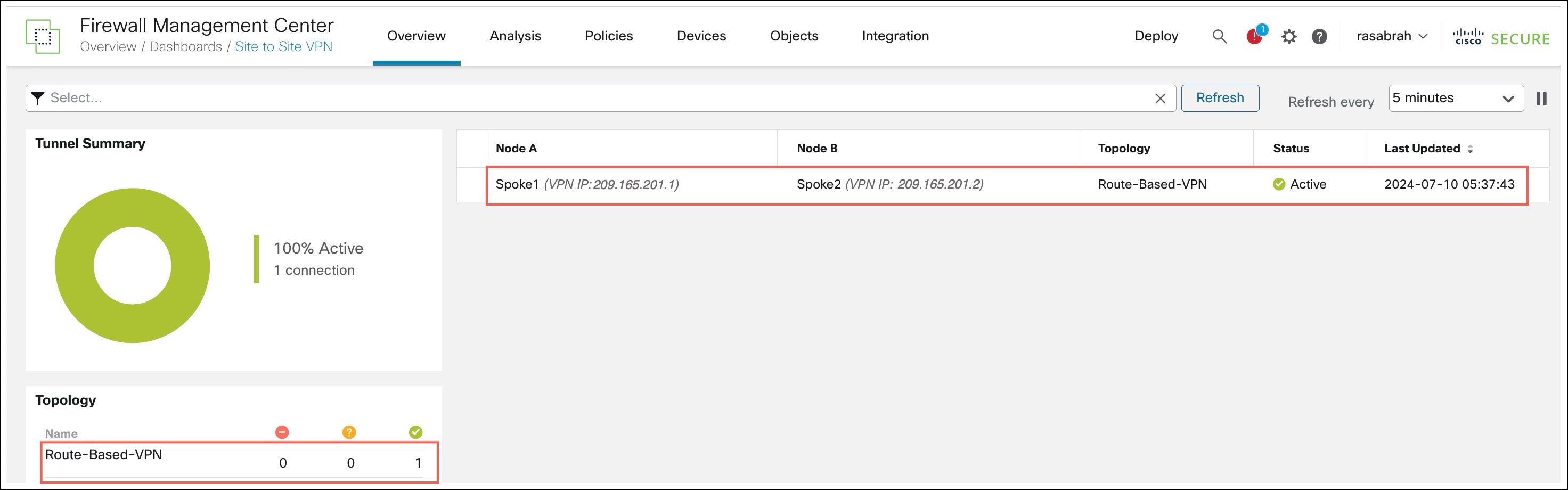
To view details of the VPN tunnel, choose Overview > Dashboards > Site to Site VPN.
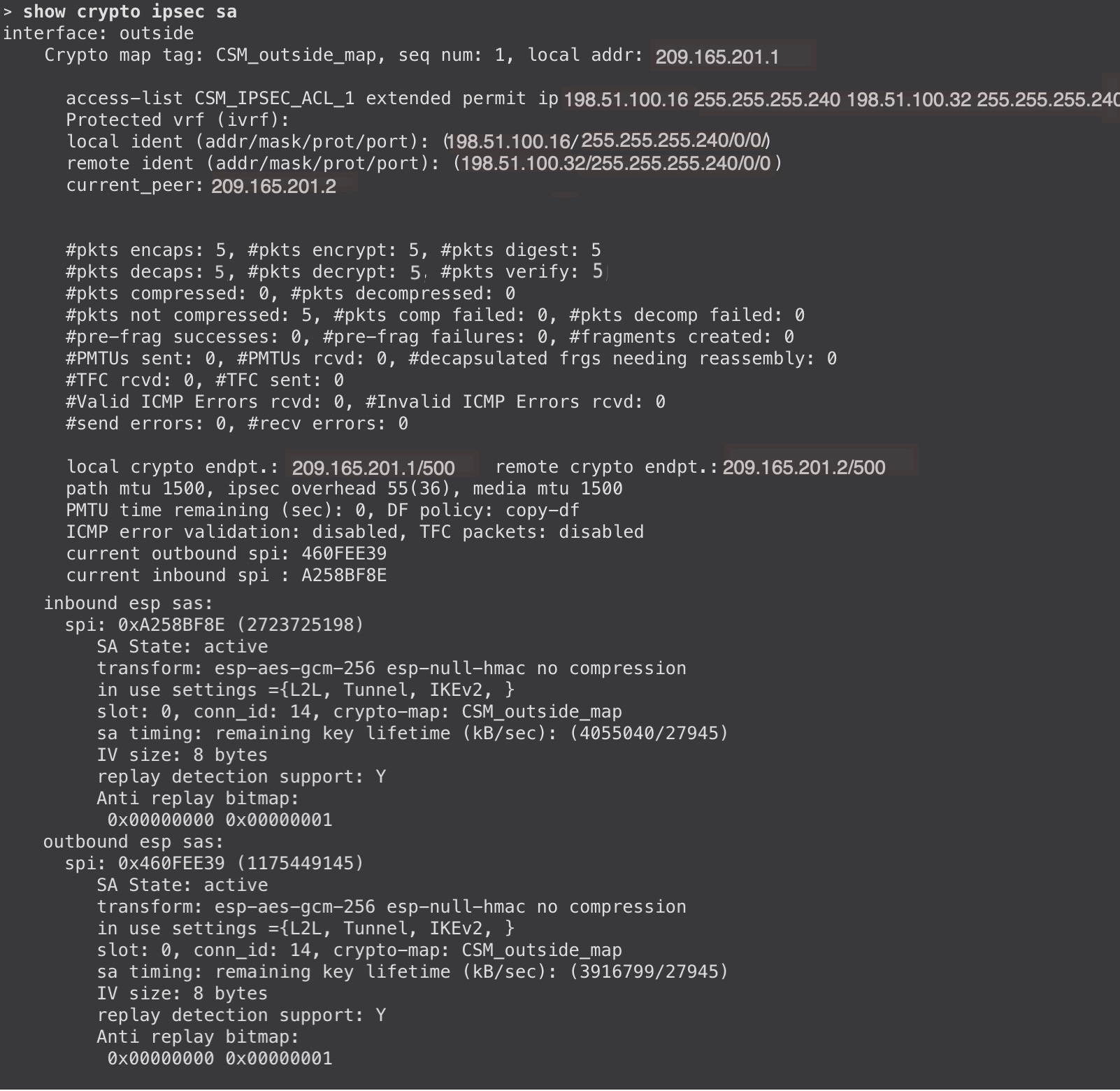
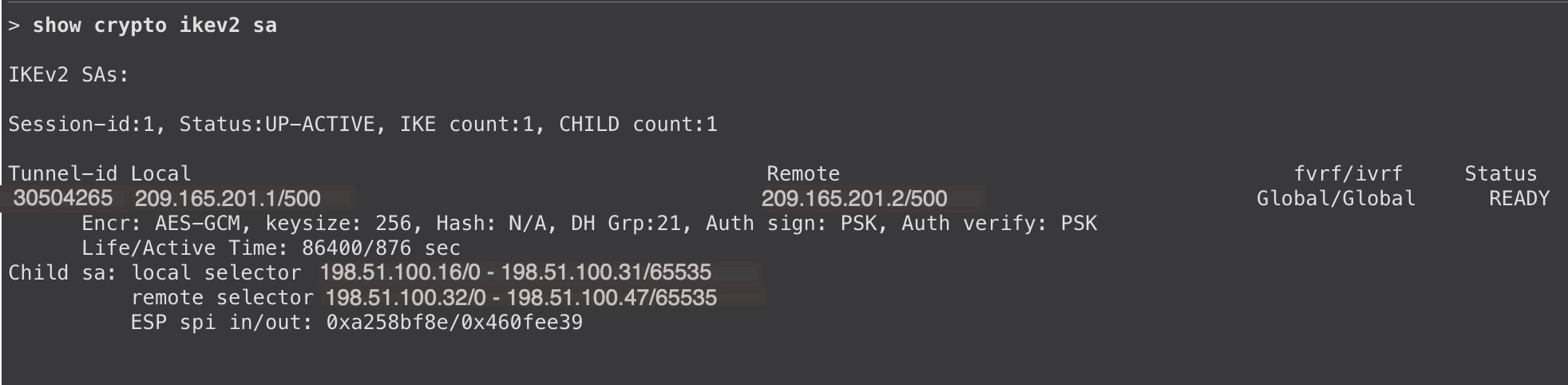
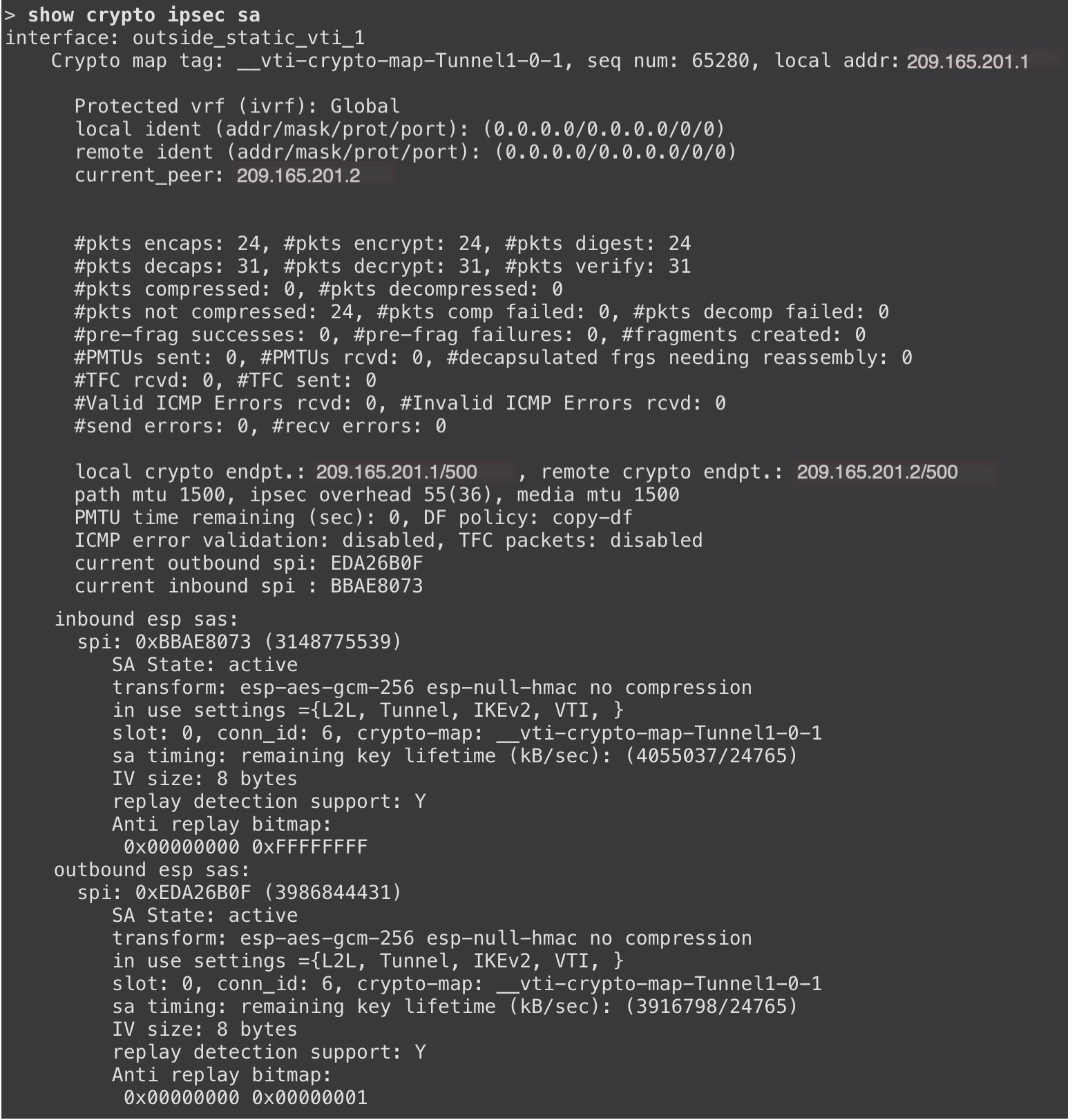
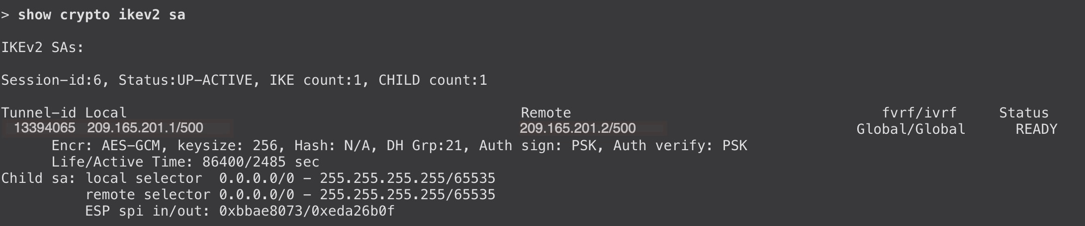
To view the tunnel details, use the show crypto ikev2 sa and show crypto ipsec sa commands on the Threat Defense devices:
Migrating a Peer-to-Peer Policy-Based VPN to a Route-Based VPN
To migrate the peer-to-peer policy-based VPN to a route-based VPN:
|
Step |
Task |
More Information |
|---|---|---|
|
1 |
Configure a peer-to-peer route-based VPN using the VPN wizard. |
|
|
2 |
Configure a routing protocol. |
|
|
3 |
Delete the policy-based VPN. |
- |
|
4 |
Deploy the configurations on the devices. |
- |
|
5 |
Verify VPN tunnel statuses and configurations. |
Configuring Peer to Peer Route-Based VPN
Procedure
|
Step 1 |
Choose Devices > Site To Site. |
|
Step 2 |
Click + Site To Site VPN. |
|
Step 3 |
In the Topology Name field, enter a name for the VPN topology. |
|
Step 4 |
Click the Route Based (VTI) radio button. |
|
Step 5 |
Select Point to Point as the network topology. |
|
Step 6 |
Check the IKEv1 or IKEv2 check box to choose the IKE version to use during IKE negotiations. |
|
Step 7 |
Click the Endpoints tab. |
|
Step 8 |
For Node A, configure the following parameters: |
|
Step 9 |
For Node B, configure the following parameters: |
|
Step 10 |
Click Save. |
Configure a Routing Protocol
For a route-based VPN, you must configure a routing protocol such as BGP, OSPF, or EIGRP. Dynamic VTI does not support static routes. In this example, we use BGP as the routing protocol.
Procedure
|
Step 1 |
Choose Devices > Device Management. |
|
Step 2 |
Click the edit icon adjacent to Spoke1. |
|
Step 3 |
Click the Routing tab. |
|
Step 4 |
In the left pane, choose General Settings > BGP. |
|
Step 5 |
Check the Enable BGP check box. |
|
Step 6 |
In the AS Number field, enter the AS number of the device. |
|
Step 7 |
Other fields are optional, and you can configure them according to your requirements. |
|
Step 8 |
Click Save. |
|
Step 9 |
In the left pane, choose BGP > IPv4. |
|
Step 10 |
Check the Enable IPv4 check box. |
|
Step 11 |
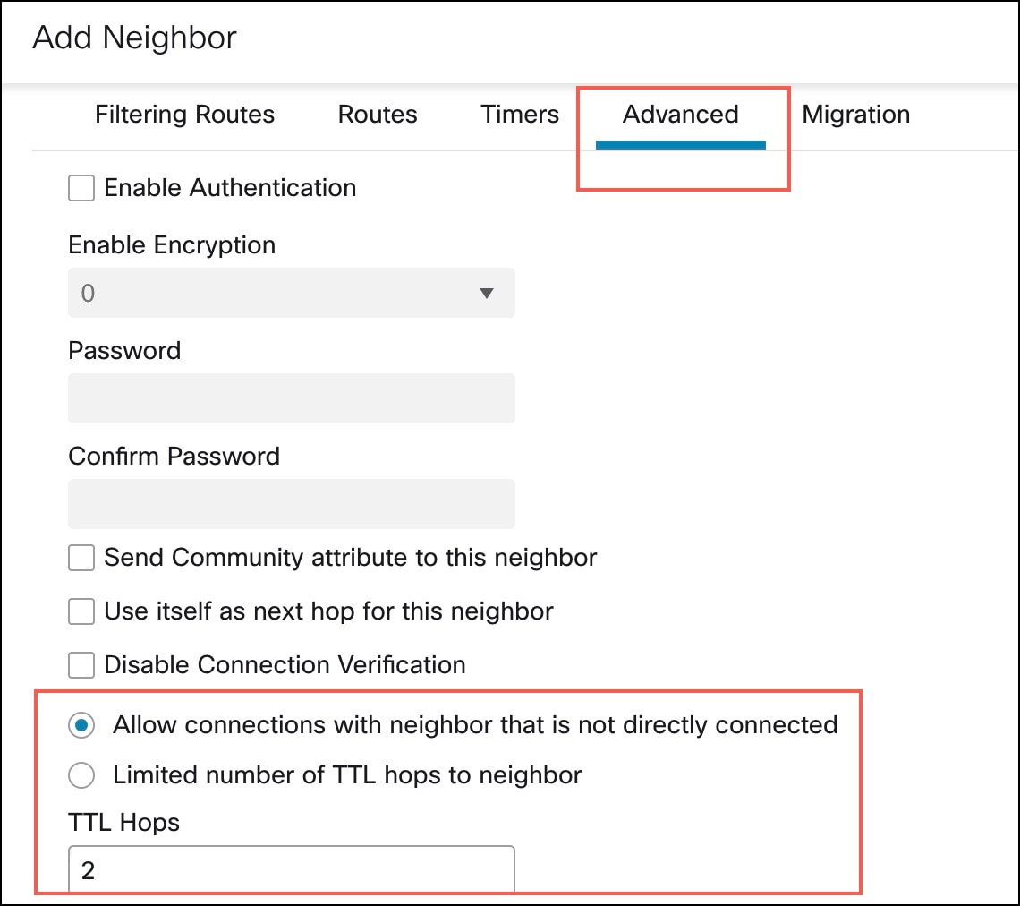
Click the Neighbor tab and click + Add. In the Add Neighbor dialog box, configure the following parameters: 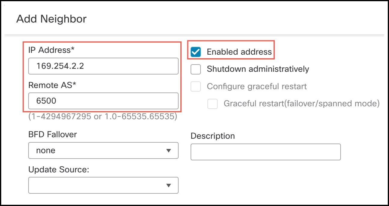
|
|
Step 12 |
Click the Networks tab and click + Add to advertise the networks to the peers. In the Add Networks dialog box, configure the following parameters: |
|
Step 13 |
Click Save. |
|
Step 14 |
To configure BGP on the peer (Spoke2), repeat Step 1 to Step 13. |
|
Step 15 |
Deploy the configurations to both the devices. |
Verify VPN Tunnel Statuses and Configurations
To view the VPN tunnel details, choose Overview > Dashboards > Site To Site VPN:
To view the tunnel details, use the show crypto ipsec sa and show crypto ikev2 sa commands on the devices.
Verify Routing Configuration on the Threat Defense Devices
To verify the BGP, OSPF, or EIGRP routes on the hub and the spokes, use the show route command on the device. You can also use the show bgp, show eigrp, or show ospf commands.
Use Case 2: Migrating a Hub and Spoke Policy-Based VPN to Hub and Spoke Route-Based VPN
Scenario
A medium-sized enterprise currently has a hub and spoke network with three Threat Defense devices (one hub and two spokes) and an extranet device. These devices are connected using a policy-based VPN, managed by a Management Center Version 7.4.1. Considering the advantages of a route-based VPN and the ability to scale the network easily, a network administrator plans to migrate this network to a route-based VPN using the management center VPN wizard.

The policy-based VPN has the following parameters:
| Device | Protected Network | VPN Interface |
|---|---|---|
| Hub | 198.51.100.16/28 | 209.165.201.1 |
| Spoke1 | 198.51.100.32/28 | 209.165.201.2 |
| Spoke2 |
198.51.100.64/28 |
209.165.201.3 |
| Extranet Spoke | 209.165.200.225/27 | 209.165.201.4 |
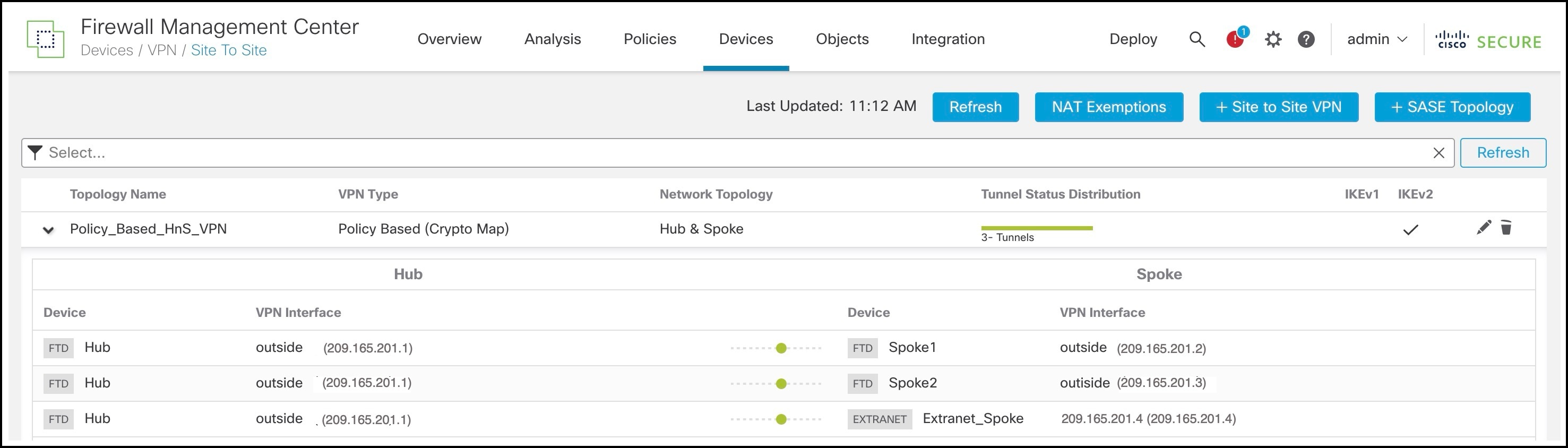
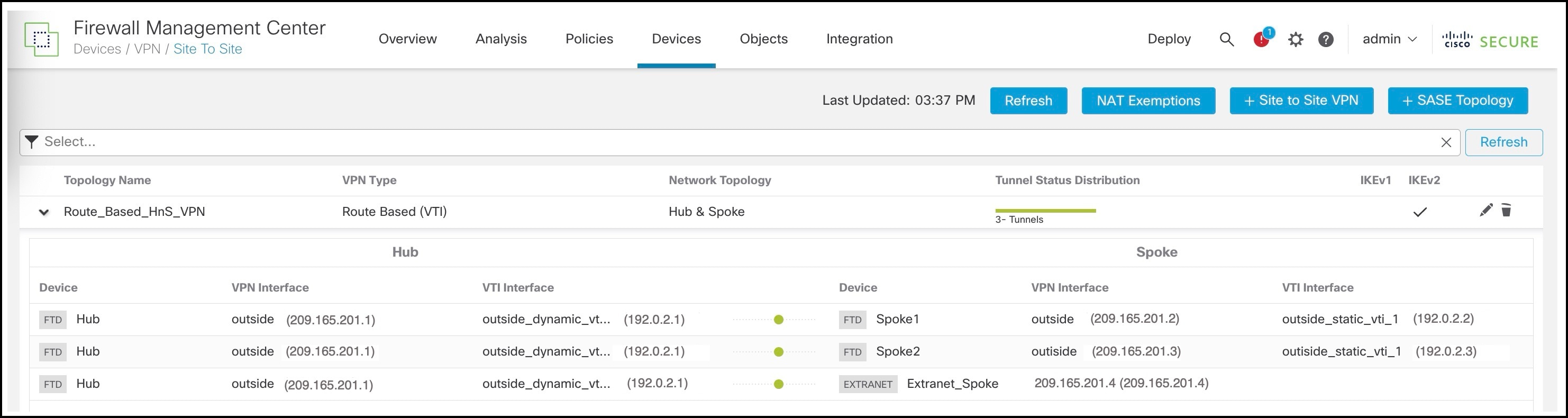
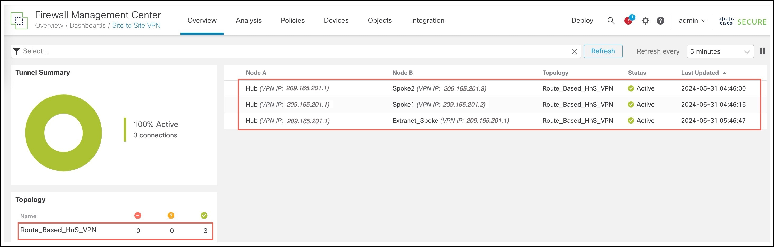
You can view the policy-based VPN in the Site-to-Site VPN Summary page:
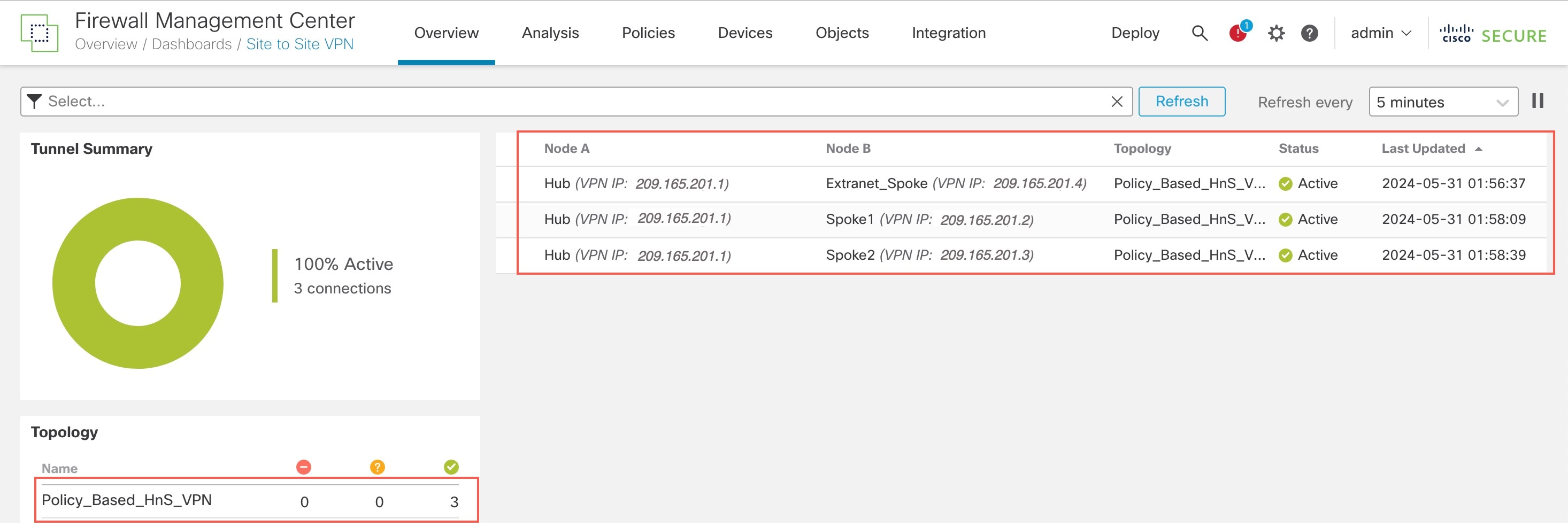
You can view details of the policy-based VPN in the Site-to-Site VPN Dashboard:
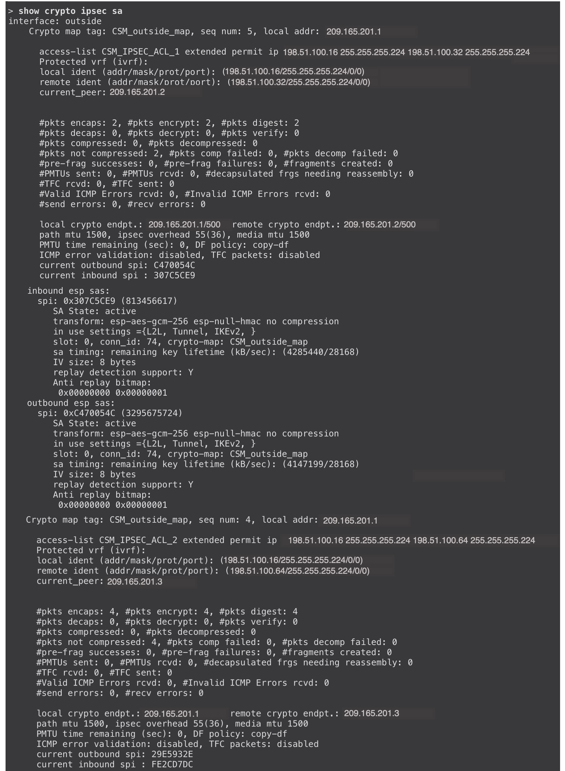
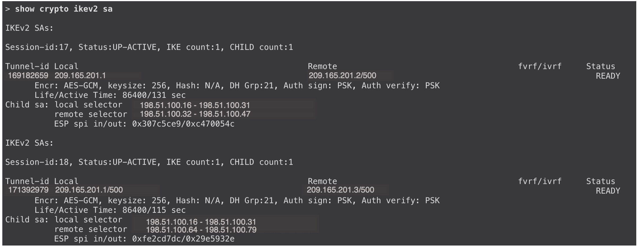
To view more details of the VPN tunnels, use the show crypto ikev2 sa and show crypto ipsec sa commands on the devices.
Migrating Hub and Spoke Policy-Based VPN to Route-Based VPN
Prerequisites
For the extranet device:
-
You must make the required configurations in the third-party deployment with the extranet device.
-
If you plan to use route-based VPN on the extranet, the extranet device must support the following:
-
Static VTI
-
BGP, OSPF or EIGRP as the routing protocol. Dynamic VTI does not support static routes.
-
-
If you plan to use policy-based VPN on the extranet, the Dynamic VTI hub supports policy-based VPN and can form tunnels with the extranet.
Procedure
To migrate the hub and spoke policy-based VPN to a hub and spoke route-based VPN:
|
Step |
Task |
More Information |
|---|---|---|
|
1 |
Configure a loopback interface on the hub and the spokes. This loopback interface emulates the VPN tunnel network on both the devices. |
|
|
2 |
Configure a hub and spoke route-based VPN using the VPN wizard. |
|
|
3 |
Configure a routing protocol. You can use BGP, EIGRP, or OSPF as the routing protocol. |
|
|
3 |
Delete the policy-based VPN. |
- |
|
4 |
Deploy the configurations on the devices. |
- |
|
5 |
Verify VPN tunnel statuses and configurations. |
Verify Tunnel Statuses and Configurations of Route-Based VPN |
Configure Loopback Interfaces on the Hub and Spokes
Procedure
|
Step 1 |
Choose Devices > Device Management. |
||||||||||||||||||||
|
Step 2 |
Click the edit icon adjacent to the device. |
||||||||||||||||||||
|
Step 3 |
Click the Interfaces tab. |
||||||||||||||||||||
|
Step 4 |
From the Add Interfaces drop-down list, choose Loopback Interface. In the Add Loopback Interface dialog box, configure the following parameters:
|
||||||||||||||||||||
|
Step 5 |
Repeat Step 1 to Step 4 to configure a loopback interface on the other two Threat Defense devices. In this example, the loopback interfaces emulating the VPN tunnel network of the devices is called Tunnel_Loopback. The table below lists the loopback interfaces of the devices used in this example:
For loopback interfaces, note the following:
|
Configure Hub and Spoke Route-Based VPN
Procedure
|
Step 1 |
Choose Devices > Site To Site. |
|
Step 2 |
Click + Site To Site VPN. |
|
Step 3 |
In the Topology Name field, enter a name for the VPN topology. |
|
Step 4 |
Click the Route Based (VTI) radio button. |
|
Step 5 |
Select Hub and Spoke as the network topology. |
|
Step 6 |
Check the IKEv1 or IKEv2 check box to choose the IKE version to use during IKE negotiations. |
|
Step 7 |
Click the Endpoints tab. |
|
Step 8 |
For Hub Nodes, configure the following parameters: In the Add Endpoint dialog box, configure the following parameters:
|
|
Step 9 |
For Spoke Nodes, click + to configure a spoke: In the Add Endpoint dialog box, configure the following parameters: |
|
Step 10 |
Repeat Step 9 to configure Spoke2. |
|
Step 11 |
To configure the extranet device, click + adjacent to Spoke Nodes. In the Add Endpoint dialog box, configure the following parameters:
|
Configure EIGRP on Hub and Spokes
If you choose EIGRP as the routing protocol, use the following procedure:
Procedure
|
Step 1 |
Choose Devices > Device Management. |
|
Step 2 |
Click the edit icon adjacent to Hub. |
|
Step 3 |
Click the Routing tab. |
|
Step 4 |
In the left pane, choose EIGRP. |
|
Step 5 |
Check the Enable EIGRP check box. |
|
Step 6 |
In the AS Number field, enter the AS number of the device. |
|
Step 7 |
Click the Setup tab. |
|
Step 8 |
From the Available Networks/Hosts list, choose the protected network and the VPN tunnel network of the device. If you do not have network objects for these networks, click + Add to create them. 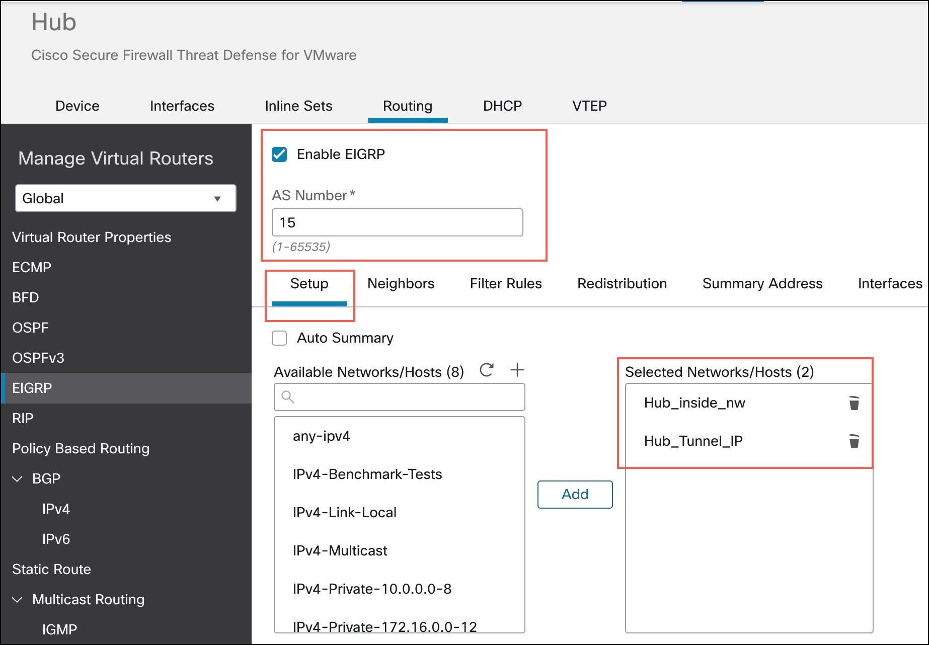
|
|
Step 9 |
Other fields are optional, configure them according to your requirements. |
|
Step 10 |
Click Save. |
|
Step 11 |
To configure EIGRP on Spoke1 and Spoke2, repeat Step 1 to Step 10. |
|
Step 12 |
Deploy the configurations to all the devices. |
Configure BGP on Hub and Spokes
If you choose BGP as the routing protocol, use the following procedure:
Procedure
|
Step 1 |
Choose Devices > Device Management. |
|
Step 2 |
Click the edit icon adjacent to Hub. |
|
Step 3 |
Click the Routing tab. |
|
Step 4 |
In the left pane, choose General Settings > BGP. |
|
Step 5 |
Check the Enable BGP check box. |
|
Step 6 |
In the AS Number field, enter the AS number of the device. |
|
Step 7 |
Other fields are optional, and you can configure them according to your requirements. |
|
Step 8 |
Click Save. |
|
Step 9 |
In the left pane, choose BGP > IPv4. |
|
Step 10 |
Check the Enable IPv4 check box. |
|
Step 11 |
Click the Neighbor tab and click + Add. In the Add Neighbor dialog box, configure the following parameters: 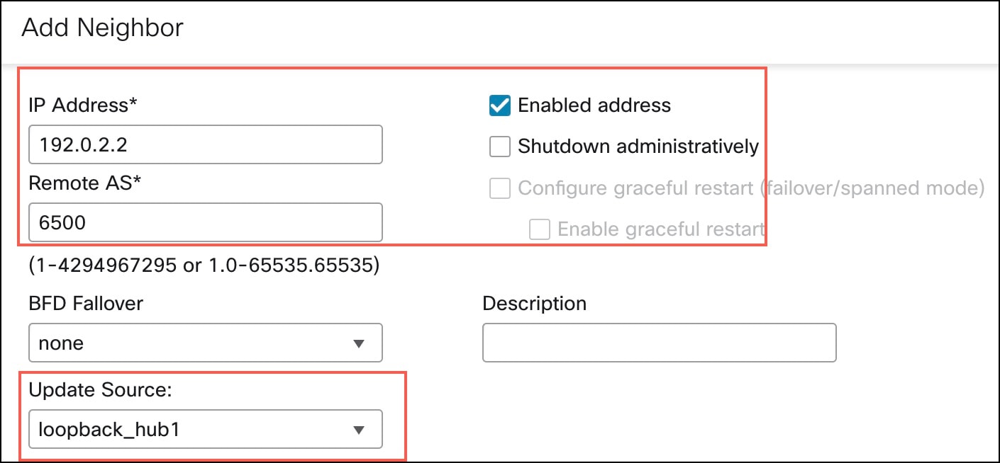
|
|
Step 12 |
To add Spoke2 as the neighbor, repeat Step 11. |
|
Step 13 |
Click the Networks tab. |
|
Step 14 |
Click + Add to advertise the networks to the peers. In the Add Networks dialog box, configure the following parameters: |
|
Step 15 |
To add the VPN tunnel network to be advertised over the tunnel, repeat Step 14. 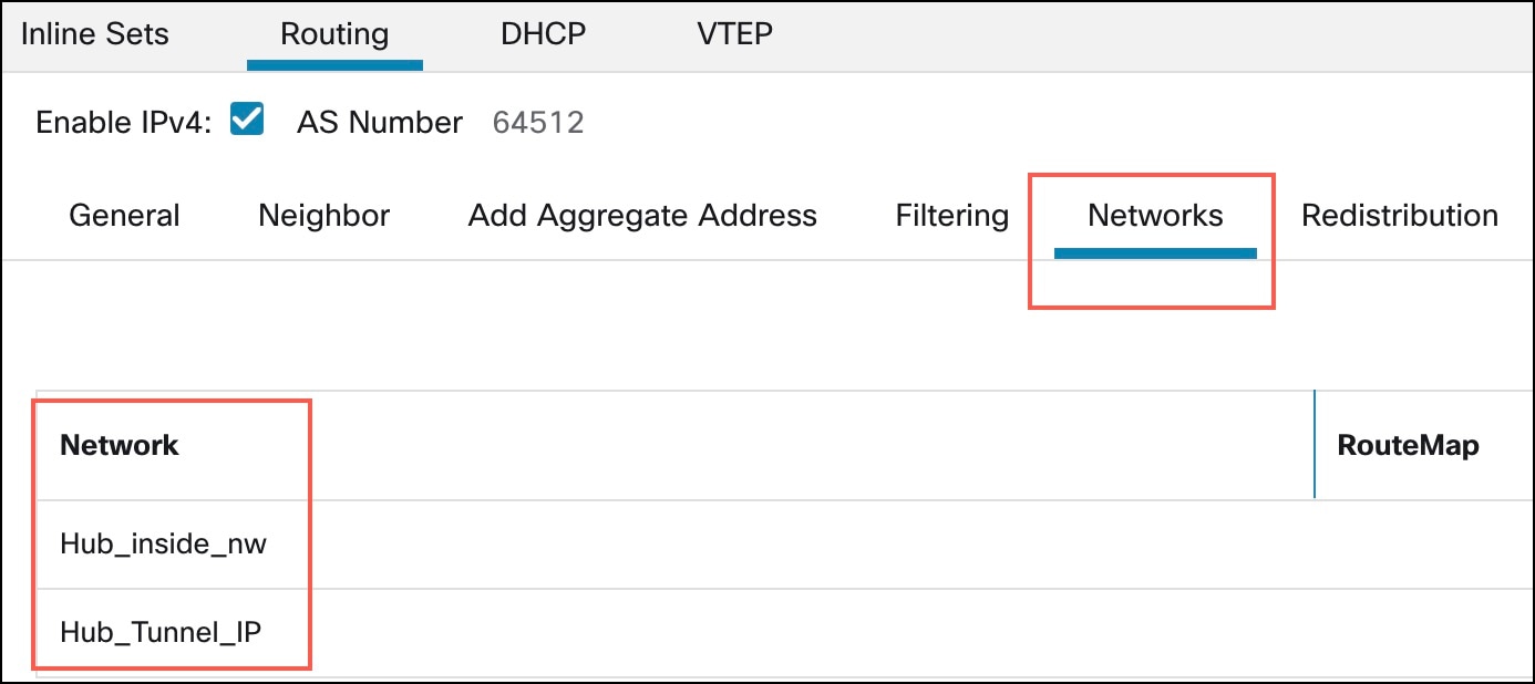
|
|
Step 16 |
Click Save. |
|
Step 17 |
To configure BGP on the peers (Spoke1 and Spoke2), repeat Step 1 to Step 16. |
|
Step 18 |
Deploy the configurations to both the devices. |
Configure OSPF on Hub and Spokes
If you choose OSPF as the routing protocol, use the following procedure:
Procedure
|
Step 1 |
Choose Devices > Device Management. |
|
Step 2 |
Click the edit icon adjacent to Hub. |
|
Step 3 |
Click the Routing tab. |
|
Step 4 |
In the left pane, choose OSPF. |
|
Step 5 |
Check the Process 1 check box to enable an OSPF instance. |
|
Step 6 |
Click the Interface tab. |
|
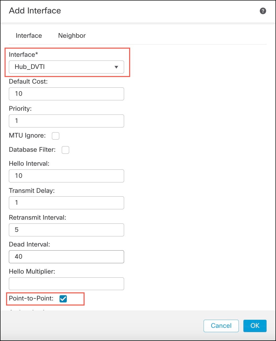
Step 7 |
Click +Add. In the Add Interface dialog box, configure the following parameters:
|
|
Step 8 |
Click the Area tab. |
|
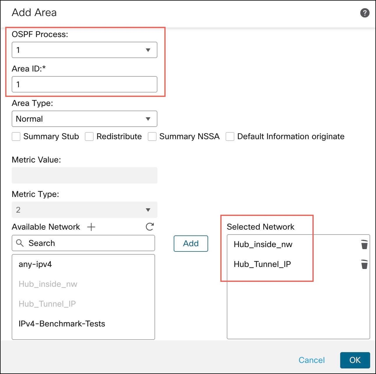
Step 9 |
Click +Add. In the Add Area dialog box, configure the following parameters:
|
|
Step 10 |
Click Save. |
|
Step 11 |
To configure OSPF on Spoke1 and Spoke2, repeat Step 1 to Step 10. |
|
Step 12 |
Deploy the configurations to all the devices. |
Verify Tunnel Statuses and Configurations of Route-Based VPN
Verify Tunnel Statuses in the Site-to-Site VPN Summary Page
To verify the statuses of the VPN tunnels, choose Device > VPN > Site To Site.
Verify Tunnel Statuses in the Site-to-Site VPN Dashboard
-
To view details of the VPN tunnel, choose Overview > Dashboards > Site to Site VPN.
-
For each tunnel, hover your cursor over a topology and click the View icon
 to view more information about the tunnels.
-
Click the CLI Details tab.
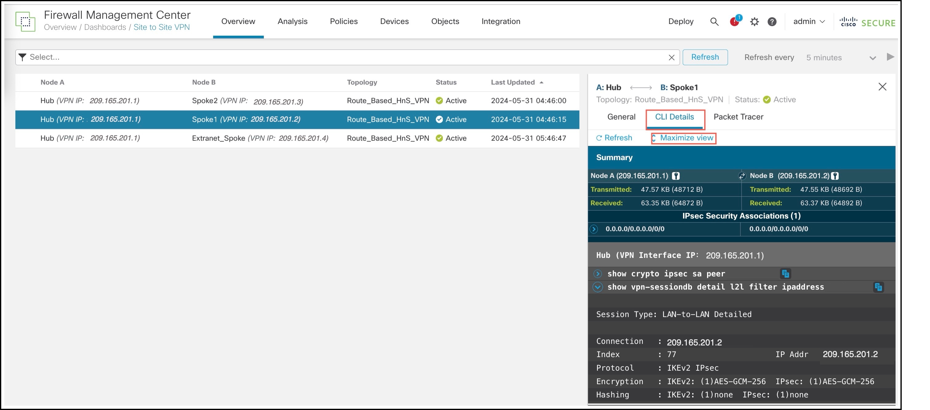
-
Click Maximize View. You can view the output of the following commands:
-
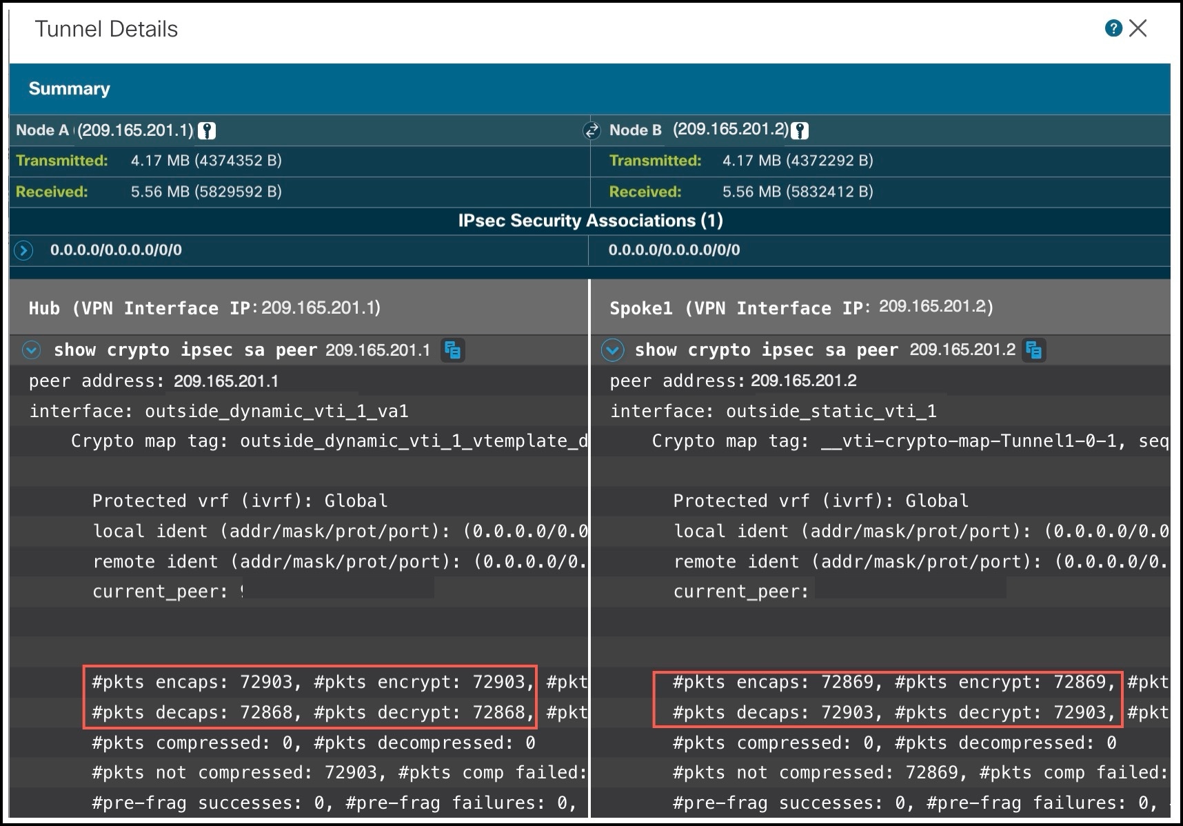
show crypto sa peer: Shows the number of packets that are transmitted through the tunnel.
-
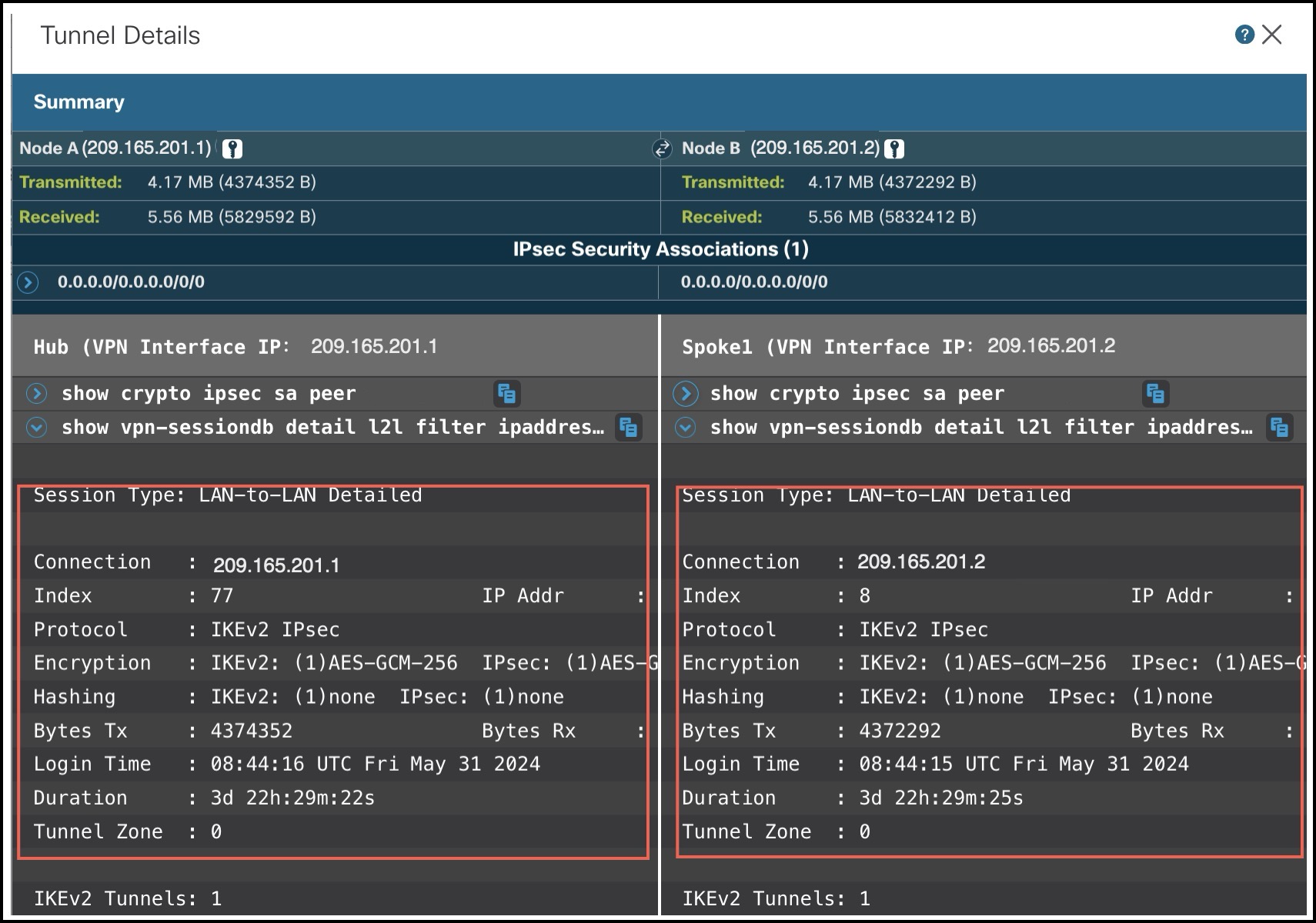
show vpn-sessiondb detail l2lfilter ipaddress: Shows more detailed data for the VPN connection.
-
Verify Routing Configuration on Threat Defense Devices
To verify the BGP, OSPF, or EIGRP routes on the hub and the spokes, use the show route command on the device using the Management Center or the device CLI. You can also use the show bgp, show ospf, or show eigrp commands.
-
In the Management Center, choose Devices > Device Management.
-
Click the edit icon adjacent to the device.
-
Click the Device tab.
-
Click CLI in the General card.
In the CLI Troubleshoot window, enter show route in the Command field and click Execute.
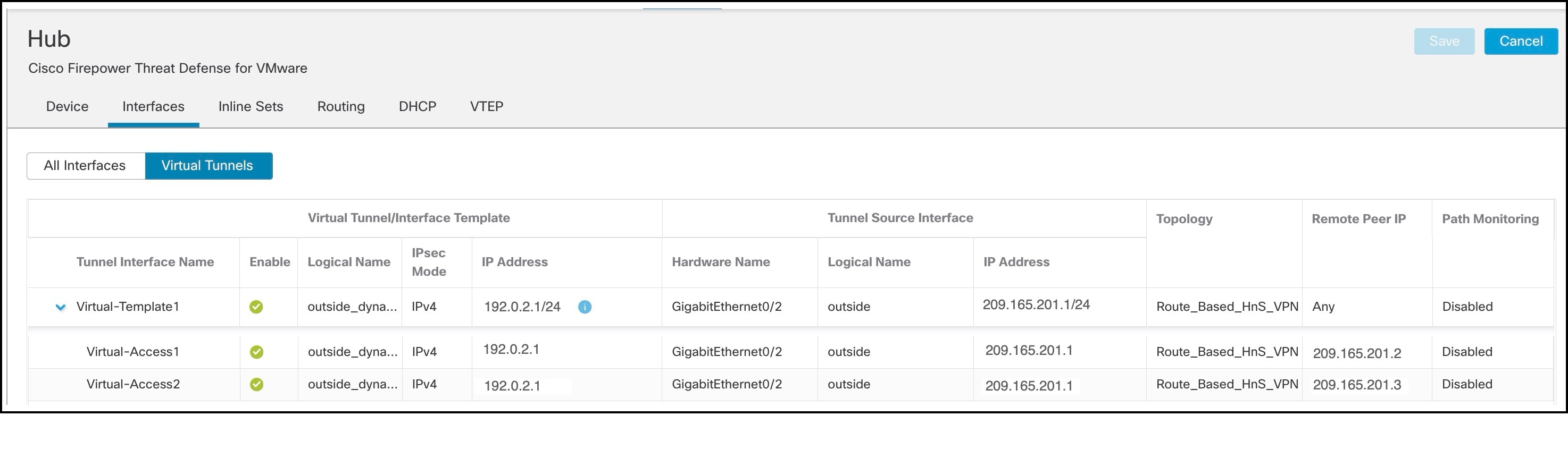
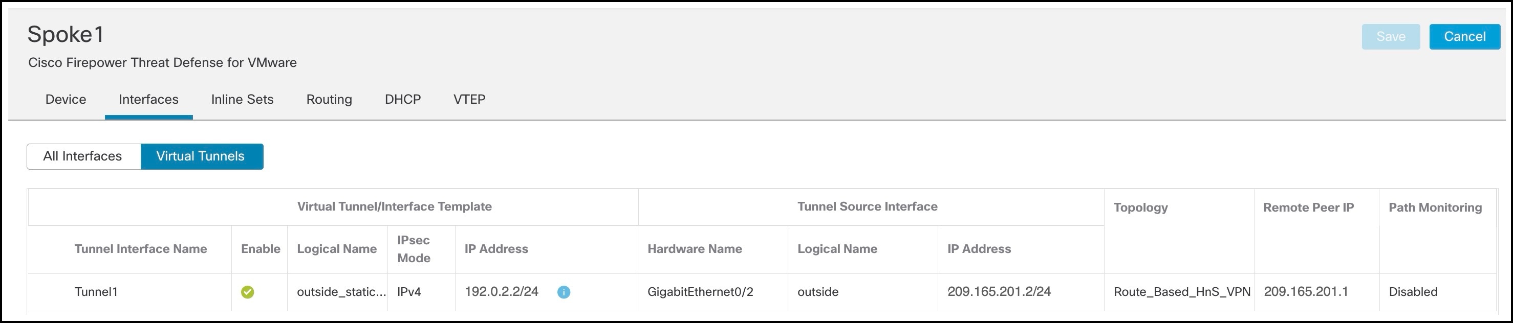
View Virtual Tunnel Interfaces of the Threat Defense Devices
To view the dynamic VTIs of hubs and static VTIs of spokes:
-
Choose Devices > Device Management.
-
Click the edit icon adjacent to the device.
-
Click the Interfaces tab.
-
Click the Virtual Tunnels tab.
For each VTI, you can view details such as name, IP address, IPsec mode, tunnel source interface details, topology, and remote peer IP.
The dynamic VTI and the dynamically created virtual access interfaces of the Hub are shown in the figure below:
The static VTI created on Spoke1 is shown in the figure below:
Troubleshoot Route-Based VPN Tunnels
After the deployment, use the following CLI commands and tools to debug issues related to route-based VPN tunnels on Threat Defense devices.
CLI and Debug Commands
|
Command |
Description |
|---|---|
|
ping |
Ping the outside IP address of the peer to the check the connectivity between the devices. |
|
show vpnsession db |
Displays summary information about current VPN sessions. |
|
debug crypto condition peer <peer-IP> |
Enable conditional debugging for a particular peer |
|
debug vti 255 |
Debug the Virtual Tunnel Interface information. |
Packet Tracer
The Packet Tracer tool allows you to test policy configurations by modeling a packet with source and destination addresses, and protocol characteristics. Besides verifying your configuration, you can use this tool to debug unexpected behaviour, such as packets being denied access.
To use a packet tracer on Threat Defense devices, choose Devices > Packet Tracer. You must be an Admin or Maintenance user to use this tool.
You can also use the Packet Tracer in the Site to Site VPN Dashboard to troubleshoot VPN tunnels between two Threat Defense devices.
-
Choose Overview > Dashboards.
-
For each tunnel, hover your cursor over a topology and click the View
icon to view more information about the tunnels.
-
Click the Packet Tracer tab.
-
Configure the parameters.
-
Click Trace Now.
-
After the trace completes, you can view the output of the trace with the results of each module.

 Feedback