Cisco Cloud First Case Study - 4Dachs2 Consulting
Available Languages
Bias-Free Language
The documentation set for this product strives to use bias-free language. For the purposes of this documentation set, bias-free is defined as language that does not imply discrimination based on age, disability, gender, racial identity, ethnic identity, sexual orientation, socioeconomic status, and intersectionality. Exceptions may be present in the documentation due to language that is hardcoded in the user interfaces of the product software, language used based on RFP documentation, or language that is used by a referenced third-party product. Learn more about how Cisco is using Inclusive Language.
- US/Canada 800-553-2447
- Worldwide Support Phone Numbers
- All Tools
 Feedback
 Feedback
Contents
Transition to Site-to-Site Connectivity Using SDCI & MPLS Providers
Transition to Multi Region Fabric (MRF) with SDCI as Backbone
Final Design – MRF with SDCI as the Primary Path & MPLS as a Secondary Path
Appendix B: Changes from Previous Versions
The designs discussed within this document are presented in the form of a case study for a fictional customer – 4Dachs2 Consulting – who is taking a cloud-first approach to providing software services to its customers by leveraging benefits of Cisco Software-Defined Cloud Interconnect (SDCI). Although 4Dachs2 is a fictional customer, the designs presented within this guide are based on actual customer deployments. The purpose of this document is as follows:
● Present design models for site-to-site and site-to-cloud connectivity.
● Highlight the benefits of the Cisco SDCI solution for connectivity between different sites and between different regions.
Audience
The audience for this document includes network design engineers, network operations personnel, and security operations personnel who wish to implement Cisco Catalyst SD-WAN networks.
4Dachs2 Consulting is a wholly owned standalone subsidiary of 4Dachs Consulting, which provides business consulting services only to select “high touch” clients. Being a recently created subsidiary, 4Dachs2 only has presence in two locations – San Jose (U.S. West Coast) and New York (U.S. East Coast).
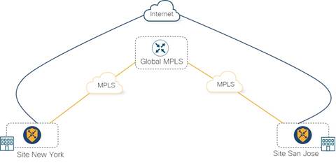
Their initial Wide-Area Network (WAN) design to provide connectivity between corporate sites was a traditional hybrid model, using Cisco Catalyst SD-WAN with MPLS as their primary WAN transport and the Internet as their secondary WAN transport.
Business Challenge & Options
As bandwidth requirements grew, 4Dachs2 was interested in exploring options to use the Internet as their primary WAN transport, rather than continuing to increase the bandwidth provisioned by the MPLS provider. However, they did not want to compromise application performance between their corporate sites because of potential bandwidth constraints due to lack of bandwidth guarantees, and sub-par link performance due to lack of latency and loss guarantees of Internet connectivity.
As they looked forward, 4Dachs2 Consulting considered the following methods of providing site-to-site connectivity between their locations:
1) Continue using connectivity via the Cisco SD-WAN fabric with their MPLS provider as their primary WAN transport, and the Internet as their secondary WAN transport.
This approach presented a challenge to them for several reasons. As bandwidth requirements rapidly increased, their ability to respond in an agile manner was limited due to longer-term contracts at specified bandwidth rates with their MPLS provider. However, the benefit of the MPLS service is that it provides 4Dachs2 with Service Level Agreement (SLA) guarantees of availability, bandwidth, loss, and latency considered necessary for them to provide consulting services to their “high touch” client base. The SLA guarantees, however, came at a higher cost of provisioning additional bandwidth over the MPLS network, rather than just provisioning additional Internet service bandwidth. 4Dachs2 also had plans to expand to sites in EMEA and APAC in the future, which would result in additional costs. They also realized it would be costly to stitch together traditional managed service provider connectivity, such as MPLS, into the various public IaaS/PaaS cloud service providers (CSPs) in the future, when that became a requirement.
2) Transition to connectivity via the Cisco Catalyst SD-WAN fabric with the Internet as their primary WAN transport, and the MPLS provider as their secondary WAN transport.
As mentioned previously, 4Dachs2 had plans to expand to additional sites in EMEA and APAC in the future. They were already concerned that the long-haul Internet connectivity between their U.S. East Coast (New York) and West Coast (San Jose) sites would involve traversing multiple Internet Service Provider (ISP) backbone networks – each with different SLAs and different peering / Internet Exchange Point (IXP) agreements with each other. This could result in little guarantees of end-to-end availability, bandwidth, latency, and loss. Expansion overseas would simply make this potential issue worse.
3) Transition to connectivity via the Cisco Catalyst SD-WAN fabric with a Software-Defined Cloud Interconnect (SDCI) provider WAN transport and an MPLS provider WAN transport.
4Dachs2 was looking for a design where they could use Internet connectivity, but would also mitigate issues resulting from loss of network connectivity, help ensure critical applications didn’t suffer performance issues, and ensure end-user application experience was optimal. The use of the Internet only for the last-mile connectivity into an SDCI provider backbone network appeared to provide 4Dachs2 exactly what they were looking for. The hybrid approach, keeping the MPLS connectivity but not necessarily increasing its bandwidth, ensured some level of WAN redundancy with SLA guarantees across both transports.
After a thorough analysis of each of the options, 4Dachs2 Consulting chose to migrate to the Cisco Catalyst SD-WAN hybrid design with SDCI and MPLS WAN transports for site-to-site connectivity. This is discussed in detail in the following section.
Transition to Site-to-Site Connectivity Using SDCI & MPLS Providers
4Dachs2 Consulting decided to use SDCI for connectivity between their corporate sites. Their chosen SDCI provider has a global infrastructure with PoPs close to their Branch and Data center locations. Each corporate site of 4Dachs2 Consulting still connects to both an Internet and an MPLS provider. However, the Internet connection is now only via a local Internet Service Provider (ISP) which provides last-mile connectivity between the corporate site and the nearest SDCI POP, as shown in the following figure.
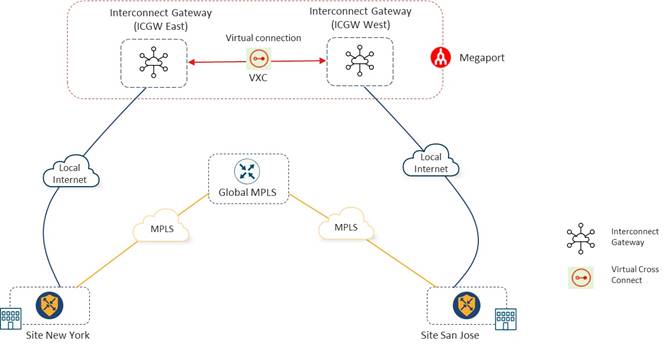
With this design 4Dachs2 Consulting can, on-demand, connect to the nearest PoP of their SDCI provider using a last-mile Internet circuit and deploy Cisco Catalyst 8000v (C8000v) instances functioning as Interconnect Gateways (ICGWs) hosted within the SDCI provider’s PoP, using Catalyst SD-WAN Manager. Each ICGW instance can automatically be provisioned to connect to every other ICGW instance using the Virtual Cross-Connects (VXCs) within the SDCI provider.
| Technical Note: |
| A Virtual Cross-Connect (VXC) is essentially a private point-to-point Ethernet connection between Interconnect Gateways (ICGW). The Layer 2 connectivity provided by the VXC is mapped to a VLAN ID on each end. |
Hence, connectivity between the SDCI POPs runs over the private backbone of the SDCI provider, not the Internet. This allows for guarantees regarding the amount of bandwidth provisioned between ICGWs running within the SDCI PoPs, as well as predictable latency and loss across the SDCI provider backbone. This mitigates the issue of not being able to provide SLA guarantees across the Internet when multiple ISPs with peering relationships between them are involved.
Since no additional hardware needs to be deployed, all virtual infrastructure (ICGWs and VXCs) can be onboarded quickly onto the customer's network infrastructure. Further, the Catalyst SD-WAN Manager’s single-pane-of-glass management allows them to take advantage of automation for connectivity and end-to-end segmentation of their deployment. The Cisco Catalyst SD-WAN solution also allows complete visibility and monitoring of the underlay.
4Dachs2 Consulting investigated Megaport and Equinix as SDCI providers. They decided to go with Megaport for the following reasons. First, their parent company, 4Dachs Consulting, already had a successful SDCI deployment with Megaport for cloud-to-cloud connectivity between different public IaaS/PaaS CSPs as discussed in the case study located at the following URL:
4Dachs2 Consulting could leverage the experience and relationship which had already been established with Megaport through their parent company. Second, 4Dachs2 was looking at using software release 17.9 / 20.9 for their network since it was a long-term release and wanted to leverage Catalyst 8000v (C8000v) instances for deployment within the SDCI PoPs – with Multi-Region Fabric (MRF) a consideration for future design.
The Cisco Catalyst SD-WAN design ensures that the traffic traversing the private backbone of Megaport is encrypted end-to-end. Hence, extending the SD-WAN fabric over the private underlay between corporate sites ensures end-to-end encryption for site-to-site traffic.
Connectivity and Traffic Flow Details
4Dachs2 Consulting used the Cloud-onRamp for Multi-Cloud – Interconnect workflow within Cisco Catalyst SD-WAN Manager to completely automate the instantiation of the ICGW instances within Megaport.
As shown in the figure above, 4Dachs2 brought up one ICGW instance in the Megaport PoP closest to their New York (U.S. East Coast) site and one ICGW instance in the Megaport PoP closest to their San Jose (U.S. West Coast) site.
SD-WAN Tunnels Across the Megaport Backbone / Fabric
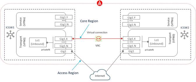
As part of the Cloud onRamp for Multi-Cloud – Interconnect workflow, 4Dachs2 Consulting brought up a Virtual Cross-Connect (VXC) between both ICGWs and assigned it the TLOC color private1.
VXCs are essentially Layer 2 point-to-point connections across the Megaport private backbone / fabric between ICGWs. VXCs can be between ICGWs within the same Megaport PoP or in different Megaport PoPs. Internally, the VXCs are connected to sub-interfaces of the GigabitEthernet1 physical interface, created within the ICGWs – one for each VXC configured for a given ICGW across the Megaport backbone / fabric.
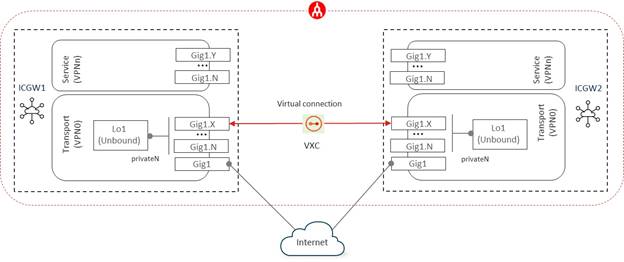
The Cloud onRamp for Multi-Cloud – Interconnect workflow configures a Loopback interface within the ICGWs. This Loopback interface is configured as follows:
● As an unbound SD-WAN tunnel interface (TLOC) – meaning the TLOC is not bound to any physical or sub-interface within the ICGW.
● Assigned a private TLOC color, which can be set in the Interconnect Global Settings within the Cloud onRamp for Multi-Cloud Interconnect workflow. This TLOC color should not be used anywhere else within the SD-WAN overlay.
● Configured for TLOC color restrict.
The combination of the unbound TLOC on the Loopback interface, the same private TLOC color for all ICGWs which have VXCs between them, TLOC color restriction, and sub-interfaces created for each VXC – ensures that SD-WAN tunnels between Loopback interfaces on different ICGWs only form across the VXCs within the Megaport backbone / fabric. A full-mesh of VXCs between ICGWs ensures reachability between all ICGWs without having to run a routing protocol on the underlay across the Megaport backbone / fabric.
Since 4Dachs2 Consulting had two sites, only a single VXC was needed and automatically provisioned through the Cloud onRamp for Multi-Cloud – Interconnect workflow. A Catalyst SD-WAN tunnel is automatically formed across that VXC connection between the two ICGWs (see Figure 3 above).
SD-WAN Tunnels Across the Internet Connection
When an ICGW is instantiated within Megaport, a public (Internet routable) IP address is assigned to the GigabitEthernet1 physical interface of the Catalyst 8000v instance (see Figure 4 above). This interface is automatically connected to the Internet as part of the automation through the Cloud onRamp for Multi-Cloud – Interconnect workflow. The GigabitEthernet1 physical interface is configured as an SD-WAN tunnel interface (TLOC) and will need to be assigned a public TLOC color. The TLOC color can be set within the VPN0 Ethernet Interface Template assigned to the Catalyst 8000v instance which will be instantiated within Megaport, through the Cloud onRamp for Multi-Cloud - Interconnect workflow. 4Dachs2 consulting set the GigabitEthernet1 interface TLOC-color to the public color of biz-internet.
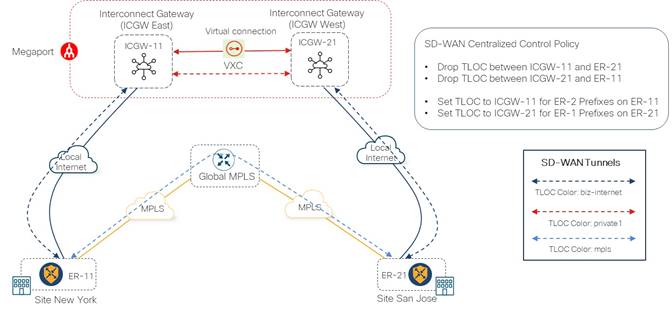
Within the Cloud onRamp for Multi-Cloud – Interconnect workflow, the GigabitEthernet1 physical interface tunnel is not configured for TLOC color restriction. Hence, it will be able to form SD-WAN tunnels with any other SD-WAN Edge device which has reachability to the public IP address of ICGW and is also not configured for TLOC color restriction (or is configured for TLOC color restriction but has the same TLOC color). Because of this, 4Dachs2 Consulting needed to configure centralized control policy to control the flow of traffic between the ICGWs and the Catalyst SD-WAN Edge Devices within their corporate sites.
For example, in Figure 3 above, traffic between SD-WAN Edge devices ER-11 and ER-21 (both in corporate sites) should not take a direct path to each other over their respective local Internet connections. In other words, an SD-WAN tunnel should not be formed directly between ER-11 and ER-21 via the interface with TLOC color biz-internet connected to the Internet. Instead, traffic from SD-WAN Edge device ER-11 needs to go to ICGW-11 using the SD-WAN tunnel with TLOC color biz-internet, then use the SD-WAN tunnel between the two ICGWs with TLOC color private1, and finally use the SD-WAN tunnel with TLOC color biz-internet between ICGW-21 and SD-WAN Edge device ER-21. Traffic flows from ER-21 to ER-11 over Internet circuit should follow same path as well. Otherwise, the SDCI backbone would not be utilized.
| Technical Note: |
| This design introduces three separate SD-WAN tunnels (hops) between the corporate sites when using the Internet transport. Features such as Application Aware Routing (AAR) work on a hop-by-hop basis. |
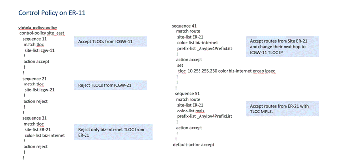
To make this happen, 4Dachs2 Consulting decided to configure centralized control policy to drop TLOCs advertised by ICGW-21 and SD-WAN Edge device ER-21 with TLOC color biz-internet, before they are sent to SD-WAN Edge device ER-11. Due to this configuration, SD-WAN Edge device ER-11 will only form an SD-WAN tunnel over the internet circuit (which has the TLOC color biz-internet) to ICGW-11.
Since SD-WAN Edge device ER-11 won’t have a direct tunnel to ICGW-21 or SD-WAN Edge Device ER-21, 4Dachs2 also needed to set the reachability to the IP prefixes advertised by SD-WAN Edge device ER-21 via the biz-internet TLOC, to be the ICGW-11 TLOC with color biz-internet. Without this configuration, traffic destined for prefixes reachable via the SD-WAN Edge device ER-21 biz-internet TLOC may get dropped by SD-WAN Edge device ER-11 if there are no other paths. This is because the routes to SD-WAN Edge device ER-21 will be in an invalid state, since they are advertised to be reachable via a TLOC (the biz-internet TLOC of SD-WAN Edge device ER-21) which is not reachable because it was dropped due to the centralized control policy.
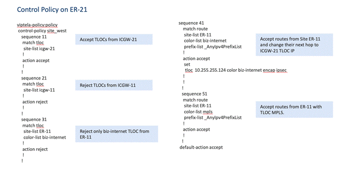
Similar centralized control policy configuration was needed to drop TLOCs advertised by ICGW-11 and SD-WAN Edge device ER-11 with TLOC color biz-internet, before they were sent to SD-WAN Edge device ER-21. Likewise, 4Dachs2 also needed to set the reachability to the IP prefixes advertised from SD-WAN Edge device ER-11 via the biz-internet TLOC, to be the ICGW-21 TLOC with color biz-internet.
The following is a summary of the centralized control policy required to send traffic between the sites over the Internet circuit (biz-internet TLOC):
● For routes sent to ER-11, drop TLOCs from ICGW-21 and drop biz-internet TLOC from ER-21.
● For routes sent to ER-11, set next hop for ER-21 prefixes to ICGW-11 TLOC IP address.
● For routes sent to ER-21, drop TLOCs from ICGW-11 and drop biz-internet TLOC from ER-11.
● For routes sent to ER-21, set next hop for ER-11 prefixes to ICGW-21 TLOC IP address.
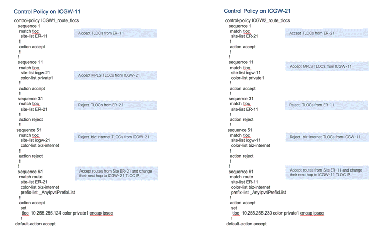
● For routes sent to ICGW-11, drop TLOCs from ER-21 and set next hop for ER-21 prefixes to ICGW-21.
● For routes sent to ICGW-21, drop TLOCs from ER-11 and set next hop for ER-11 prefixes to ICGW-11.
Please see Appendix A for an example of the complete centralized control policy.
Once the ICGWs were up within Megaport, SD-WAN Edge device ER-11, located within the New York corporate site, built an SD-WAN tunnel to ICGW-11 within the East Coast Megaport PoP, using the local Internet circuit. Similarly, SD-WAN Edge device ER-21, located within the San Jose corporate site, built an SD-WAN tunnel to ICGW-21 within the West Coast Megaport PoP, using the local Internet circuit.
After configuring and deploying the policy, 4Dachs2 Consulting was able to load balance the traffic between both the MPLS and the Megaport SDCI WAN transport interfaces between their corporate sites (ER-11 and ER-21). In the future, further adjustments to policy could then be done such that specific application traffic could favor specific transports as needed to take into account potential bandwidth differences between the SDCI and MPLS transports over time.
Addition of Site-to-Cloud Connectivity
As had been anticipated, soon after transitioning to Cisco Catalyst SD-WAN using SDCI along with MPLS, 4Dachs2 needed to extend their corporate sites into multiple public IaaS/PaaS Cloud Service Providers (CSPs).
As their fledgling consulting services grew, they quickly ran out of physical space for additional servers used to support the applications necessary for their consulting services. Rather than acquire new facilities with space for building larger on-prem private data centers, they decided on a cloud-first approach – beginning with new application development. Existing applications used to support their consulting services would remain within their on-prem private data centers if there was sufficient compute capacity. New applications would be developed and deployed within public IaaS/PaaS CSPs.
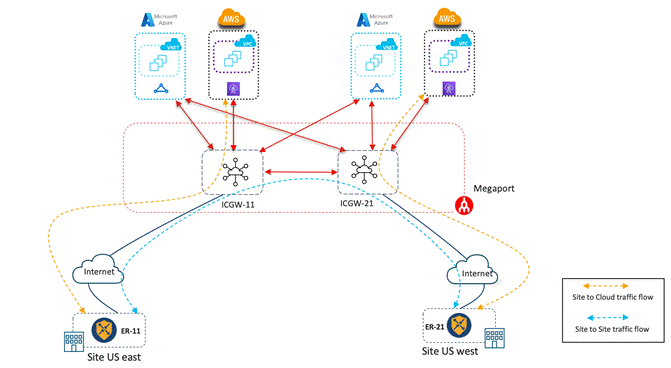
4Dachs2 decided on a similar approach to connecting to public IaaS/PaaS CSPs as their parent company, 4Dachs Consulting. They would leverage the existing connectivity to their SDCI partner, Megaport, to connect into multiple public IaaS/PaaS CSPs – beginning with Amazon Web Services (AWS) and Microsoft Azure - via private connectivity (Direct Connect and ExpressRoute). An example of their connectivity is shown in the following figure.
This model extended a single Service VPN into the public IaaS/PaaS CSPs, as discussed in Option 1: Extending the SD-WAN Fabric into the SDCI Partner Network Only within the Cisco Cloud First Case Study - 4Dachs Consulting guide located at the following URL:
4Dachs2 Consulting decided to extend connectivity into each public IaaS/PaaS CSP from the SDCI PoP within each geographic region – U.S. East and U.S West, as shown in the figure above.
With this design both the SDCI and MPLS WAN transport links can be used to send site-to-site traffic while the SDCI transport link provides site-to-cloud connectivity. Cloud-to-cloud connectivity between IaaS/PaaS CSPs leverages private connectivity (AWS Direct Connect and/or Azure ExpressRoute) along with the Megaport backbone / fabric where needed. Although the design only provides connectivity to the public IaaS/PaaS CSPs via a single WAN transport (SDCI), it also mitigates the additional costs of having to extend the MPLS provider into the public IaaS/PaaS CSPs. Overall, this ensured the necessary SLA guarantees of bandwidth, low latency, and low packet loss for site-to-site, site-to-cloud, and cloud-to-cloud traffic within 4Dachs2 Consulting’s Catalyst SD-WAN network.
Transition to Multi Region Fabric (MRF) with SDCI as Backbone
The deployment of Cisco Catalyst SD-WAN using both SDCI and MPLS worked out successfully, providing the necessary guarantees of bandwidth and availability, along with deterministic latency and low packet loss for their consulting services applications. This helped drive the success of 4Dachs2 Consulting.
Over time they expanded, adding multiple sites in the EMEA and APAC geographic regions, as well as additional sites in the U.S. West and U.S. East regions. Since 4Dachs2 Consulting was now a global company with branches across different geographic regions, one key design considerations was to provide the same SLA guarantees and link performance across all regions for site-to-site, site-to-cloud, and cloud-to-cloud connectivity.
4Dachs2 Consulting decided to transition to a Catalyst SD-WAN Multi-Region Fabric (MRF) design for connectivity between different geographic regions, continuing with their SDCI provider across all regions to provide the solution for the following challenges for inter-region connectivity:
● End-to-end encryption for inter-region traffic.
● SLA guarantees of bandwidth, latency, and loss, as well as better link performance for inter-region connectivity.
● Site-to-site and site-to-cloud connectivity between different regions.
● Simplified configuration with the flexibility to select the best transport for inter-region and intra-region connectivity.
Multi-Region Fabric (MRF) Overview
The Cisco Catalyst SD-WAN Multi-Region Fabric (MRF) architecture provides separation between regional networks (also referred to as access regions) through a core region, as shown in the following figure.
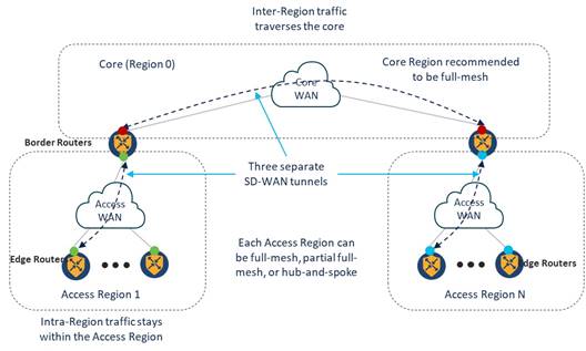
In an MRF design, Catalyst SD-WAN routers are assigned one of two roles – Edge Router (ER) or Border Router (BR). Edge Routers operate within a single access region. The exception to this is when an Edge Router is configured to operate in a secondary region – which will be discussed in the MRF SDCI Design with Redundancy and Backup Path section of this guide. Border Routers operate in both a single access region and the core region. The core region is also referred to as Region 0.
The Cisco SD-WAN Overlay Management Protocol (OMP) has been enhanced to include region awareness when MRF is enabled within a Catalyst SD-WAN overlay. Edge Routers include the region ID in which they are configured, within OMP routing updates sent to the SD-WAN Controllers to which they are peered.
Border Routers are special in that they have OMP peering with two sets of SD-WAN controllers:
● The set of SD-WAN Controllers within the access region in which they operate.
● The set of SD-WAN Controllers within the core region.
Border Routers redistribute OMP routes from an access region into the core region and vice-versa, as shown in the following figure.
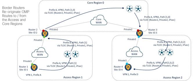
As Border Routers redistribute OMP routes from an access region into the core region, they append the core region ID (Region 0) to the routes, which are then sent to the SD-WAN Controllers operating within the core region. The SD-WAN Controllers within the core region then reflect those OMP routes to the other Border Routers within the SD-WAN overlay.
Likewise, as Border Routers redistribute OMP routes from the core region into an access region, they append the core region ID to the routes which are then sent to the SD-WAN Controllers operating within the access region. The SD-WAN Controllers within the access region then reflect those OMP routes to the Edge Routers within the access region. The region ID path provides a mechanism for loop detection and avoidance, similar to how the Autonomous System Number (ASN) path provides loop detection and avoidance within the Border Gateway Protocol (BGP).
The redistribution of routes between access regions and the core region can simplify or potentially eliminate the need for complex centralized control policy required to send traffic between the sites, as discussed earlier in the Transition to Site-to-Site Connectivity Using SDCI & MPLS Providers section of this document. Redistribution of routes also eliminates certain scenarios where traffic is black-holed (discarded or dropped without informing the source that the traffic did not reach its intended destination) which can result from static SD-WAN policy applied to a network with multiple SD-WAN hops. The simplification and/or elimination of policy was highly desirable for 4Dachs2 Consulting, since they had limited staff to maintain and expand the Cisco Catalyst SD-WAN deployment as they continued to grow.
| Technical Note: |
| Please refer to the following link for configuring Multi-Region Fabric (MRF) within a Cisco Catalyst SD-WAN deployment. |
4Dachs2 Consulting - Initial MRF Design Considerations
As their initial MRF design, 4Dachs2 Consulting considered configuring the following four access regions, based up the geographic regions in which they were operating:
1. Region 1 for U.S. East sites
2. Region 2 for U.S. West Sites
3. Region 3 for European (EMEA) Sites
4. Region 4 for APAC Sites
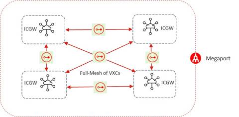
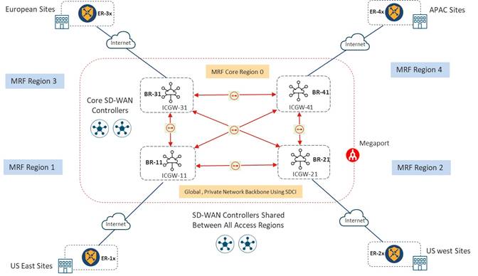
Full-Mesh Core VXC and SD-WAN Tunnel Data Plane Design
4Dachs2 Consulting decided to use SDCI for the core region – continuing with Megaport as the provider – to simplify configuration and to provide cost-effective, reliable connectivity between access regions and Border Routers. Within each access region an Interconnect Gateway (ICGW) is brought up and configured as a Border Router. The ICGWs form the core region and have full-mesh VXC connectivity between each other, as shown in the following figure.
| Technical Note: |
| Note that MPLS connectivity to each of the corporate sites is not shown in the figure above to focus the discussion on the MRF aspects of the design. The upcoming Final Design – MRF with SDCI as the Primary Path & MPLS as a Secondary Path section of this document discusses the final design for 4Dachs2 Consulting, in which the MPLS circuits are included as part of a secondary access region for the purpose of redundancy. |
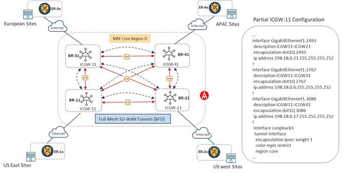
With this design, each access region has one ICGW assigned the role of a Border Router to provide connectivity for inter-region traffic. The GigabitEthernet1 interface of each ICGW is assigned its respective access region and the Loopback1 (Lo1) interface assigned to the core region, as shown in the following figure.
After enabling the VXC connections between each ICGW using the Cloud onRamp for Multi-Cloud – Interconnect workflow from Catalyst SD-WAN Manager and assigning the Border Role to the ICGWs, a full-mesh of SD-WAN tunnels was formed between all Border Routers, as shown in the following figure.
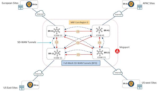
Note that a full-mesh of SD-WAN tunnels within the core region is a recommendation but not a requirement of Cisco for the MRF architecture. This will be explored further in the upcoming Consideration of Partial-Mesh VXC Connectivity Between Border Routers section of this guide.
| Technical Note: |
| From this point forward in the document, the term Border Router (BR) will be used interchangeably for ICGW to simplify the discussion. Border Router and Interconnect Gateway (ICGW) are interchangeable words when deploying MRF with an SDCI design in which the core is deployed within the SDCI provider network. CLI add on template will be required to enable “region core” under Loopback’s tunnel-interface of Border Router after the SDCI workflow. MRF settings has been added in SDCI workflow from 17.10/20.10. |
With a full-mesh of VXCs and therefore a full-mesh of SD-WAN tunnels in the design, each Border Router will have 3 VXC connections and therefore 3 SD-WAN tunnels towards other Border Routers in the core region. As shown in the partial configuration within the figure below, Border Router BR-11 has three Layer 2 sub-interfaces which create point-to-point connectivity between all other Border Routers. The Loopback 1 (Lo1) interface is configured as an unbound tunnel interface (TLOC) – meaning it is not bound to any of the sub-interfaces.
4Dachs2 Consulting understood there are certain limitations of configuring a Loopback interface as the tunnel interface, such as per-tunnel QoS not being supported. However, per-tunnel QoS is only supported in a hub-and-spoke topology. Since the MRF core is recommended to be configured with a full-mesh of SD-WAN tunnels between Border Routers within the access regions, this was not a concern to them.
Control Plane Design
From a control plane perspective, the core region has a dedicated pair of SD-WAN Controllers, as recommended by Cisco (See Figure 9 above). The initial thoughts of 4Dachs2 Consulting were that the U.S. East and U.S. West regions would share pair of SD-WAN Controllers. 4Dachs2 Consulting also considered a dedicated pair of SD-WAN Controllers for the APAC and EMEA regions as well. However, after running through the calculations regarding the number of DTLS/TLS control connections, OMP sessions, and the estimated OMP routes received (RIB-in) and routes sent (RIB-out), they saw no reason why a single set of SD-WAN controllers for all access regions was not sufficient – given the relatively small size of their deployment. Should 4Dachs2 Consulting need to split the APAC and EMEA regions into a separate set of SD-WAN Controllers, they could do so in the future.
Consideration of Partial-Mesh VXC Connectivity Between Border Routers
The Megaport SDCI fabric supports private site-to-site connectivity between ICGWs, and therefore it is not always necessary to have a full-mesh of site-to-site connectivity when ICGW routers are configured as Border Routers. Likewise, the Cisco SD-WAN MRF architecture recommends, but does not require a full-mesh of SD-WAN tunnels across the core region.
The total number of VXC connections required within the SDCI fabric for a full-mesh design can be determined by the equation n * (n -1) / 2 where n is the number of ICGWs. With a single ICGW, functioning as a Border Router in each of the 4 access regions, 4Dachs2 Consulting needed to provision a total of 4 * (4 – 1) / 2 = 6 VXC connections. However, if 4Dachs2 Consulting added one more access region, the number of VXC connections required increases to 5 * (5 -1) / 2 = 10 VXC connections.
4Dachs2 Consulting realized that as they grew, the cost of adding additional VXC connections to maintain a full-mesh of VXC connections within the Megaport SDCI fabric would also increase. Hence, 4Dachs2 Consulting considered the following two additional design options for connectivity between Border Routers:
· Option 1: Partial mesh VXC connectivity and partial mesh SD-WAN tunnels between Border Routers
· Option 2: Partial mesh VXC connectivity and full mesh SD-WAN tunnels between Border Routers
Option 1: Partial-Mesh VXC Connectivity and Partial-Mesh SD-WAN Tunnels Between Border Routers
As shown in the figure below, Border Routers can be configured in such a way that they have only 2 VXC connections, which can be used to form direct connections with 2 other Border Routers.
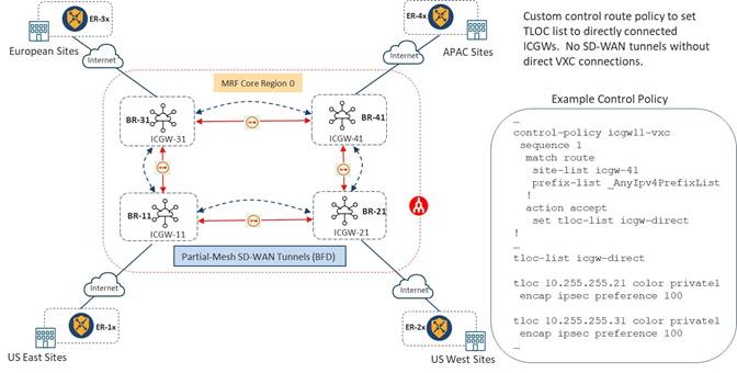
In the example above Border Router BR-11 has Layer 2 connectivity to Border Routers BR-21 and BR-31 through VXC connections. However, Border Router BR-11 has no VXC connection, and hence no Layer 2 connectivity, with Border Router BR-41. With this design, by default, Border Router BR-11 will be able to form SD-WAN tunnels to Border Routers BR-21 and BR-31 but will not be able to form an SD-WAN tunnel with BR-41.
To overcome the lack of VXC connectivity between Border Routers BR-11 and BR-41, centralized control policy can be configured to route traffic from Border Router BR-11 destined for prefixes reachable via Border Router BR-41 through Border Routers BR-21 and BR-31, and vice-versa. Specifically, centralized control policy can be configured to match any prefix for site-list ICGW-41 and use the “set TLOC” configuration within the action, to send traffic to Border Routers BR-21 and BR-31. A TLOC-list can be created with equal preference to load balance traffic between Border Routers BR-21 and BR-31.
| Technical Note: |
| The preference can be changed within the TLOC-list for each TLOC to make one VXC link primary and second VXC link as a backup if desired. |
This design helps in reducing number of VXC connections. Since each VXC provisioned has a separate cost, reducing the number of VXC connections can be one criteria for optimizing the recurring cost of the infrastructure. However, this design also increases the complexity of the solution by introducing control policy within the MRF core. Since control policy is a static construct, it also cannot solve the design challenge of black-holing traffic if the VXC link between Border Router BR-41 and either Border Router BR-21 or Border Router BR-31 is down.
Due to these issues 4Dachs2 Consulting decided not to proceed with the option of partial-mesh VXC connectivity with partial-mesh of SD-WAN tunnels between Border Routers.
Option 2: Partial mesh VXC connectivity and full mesh SD-WAN tunnels between Border Routers
If Border Routers are configured with partial-mesh VXC connectivity, it is still possible to establish full-mesh SD-WAN tunnel connectivity. This was the second option that 4Dachs2 Consulting considered.
As shown in the figure below, a routing protocol can be enabled in the underlay of the ICGWs which form the MRF core. A routing protocol can help in advertising the connected links between the sites that do not have direct connectivity. Thus, a full logical mesh of SD-WAN tunnels over a partial-mesh of VXC connections can be created between all the Border Routers.
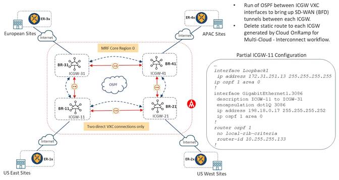
In the figure above, Border Routers BR-11 and BR-21 are connected through a VXC. Similarly, Border Routers BR-11 and BR-31 are connected through another VXC. However, there is no direct VXC connection between Border Routers BR-11 and BR-41.
In this scenario, Border Router BR-11 can form an SD-WAN tunnel to Border Router BR-41 by using the VXC between BR-21 and BR-31. IP reachability between Border Routers BR-11 and BR-41 is discovered through the OSPF routing protocol running in the underlay. On all ICGWs, the Loopback 1 (Lo1) interface and the sub-interfaces of GigabitEthernet 1 on which the VXC connection are terminated, run the OSPF routing protocol.
By default, the Cloud onRamp for Multi-Cloud – Interconnect workflow within the Catalyst SD-WAN Manager will configure a static route on each ICGW, pointing towards the Loopback 1 (Lo1) IP address of the other ICGW available via IP address corresponding to the remote side of the VXC through which the other ICGW is reachable. These static routes need to be manually removed to prefer routes learned via OSPF.
Since there are two paths to reach Border Router BR-41 from Border Router BR-11 – one through Border Router BR-21 and the other through Border Router BR-31, OSPF metrics can be used to prefer one path over the other. With this design an SD-WAN tunnel between Border Routers BR-11 and BR-41 will be establish - either through Border Router BR-21 or Border Router BR-31. Similarly, Border Router BR-21 will establish an SD-WAN tunnel with Border Router BR-31 – either through Border Router BR-11 or Border Router BR-41. Each Border Router will establish three SD-WAN tunnels and will establish a full-mesh of BFD connections with each other.
With the help of a routing protocol running in the underlay, this design eliminates the need for control policy. It can also provide predictability during a link failure event for indirectly connected ICGWs. As with the previous option, this design helps in reducing number of VXC connections and therefore can help reduce the recurring costs of the infrastructure. However, this design does require manual modification of the configuration provisioned by the Cloud onRamp for Multi-Cloud workflow after instantiation of the ICGWs within the Megaport SDCI fabric.
Dual Border Router Designs – Redundancy in Core Region
While working on their core connectivity design, 4Dachs4 Consulting also looked at the issue of redundancy in core region. If all access regions (geographical regions) connect to the core region through only one Border Router this can result in a failure of inter-region connectivity for a site if its Border Router fails. After considering the issue, 4Dachs2 Consulting decided to bring up another ICGW in each access region within Megaport to provide redundancy within the PoP of each region.
| Technical Note: |
| For an additional level of redundancy each of the ICGWs could be instantiated within different Megaport PoPs which are regionally close to each other within a given access region. This protects against the failure of a specific Megaport PoP. |
Because the number of Border Routers increases from 4 to 8, the number of VXC connections required for full VXC connectivity between all Border Routers increases to (8 * (8 – 1) / 2) = 28.
Since redundancy in the core region is a requirement for 4Dachs2 Consulting, they also looked at the option of using OSPF to help in reducing the number of VXC connection between ICGWs. As shown in the figure below, by running OSPF in the underlay and only building 3 point-to-point VXC connections to each ICGW, the total number of VXC connections can be reduced from 28 to 12 in the design.
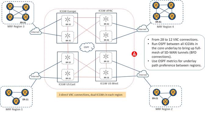
Alternative Connectivity Options to Border Routers within Each Access Region
As each of the access regions expanded beyond a single site (and therefore a single router), 4Dachs2 Consulting also considered various designs by which the Edge Routers connected to the Border Routers within the access region. The exercise was simply to see if there were any advantages / disadvantages of not having all Edge Routers directly connecting to the Border Routers within an access region.
As shown in the figure below, within MRF Region 3, Edge Router ER-31 can be connected to Border Routers BR-31 and BR-32 within a Megaport PoP. With this type of design, Edge Router ER-31 can still be considered an Edge Router for MRF Region 3, although traffic from all other Edge Routers within Region 3 pass through it to traverse to another region.
This design might be beneficial if a single private transport such as regional MPLS was used for intra-regional traffic, but the organization still wanted to leverage the SDCI transport for inter-regional traffic. Alternatively, for very large access regions, the number of SD-WAN tunnels that need to be supported by the Border Routers could become excessive if all Edge Routers formed direct tunnels with the Border Routers.
In such a scenario, a local Internet transport – necessary for connectivity into the Megaport SDCI PoP – would only need to be provisioned for a single site, not for all sites within the access region. 4Dachs2 Consulting also noted, however, that since there could be dis-contiguous networks (local Internet and regional MPLS) connected to Edge Router ER-31, additional functionality such as the Transport Gateway functionality may need to be enabled on that Edge Router. Alternatively centralized policy could be configured within the access region.
A downside to this design is that Edge Router ER-31 represents a single point of failure for Region 3. However, as shown in Region 4, in the figure above, multiple Edge Routers within a given access region can connect to Border Routers in core region. This eliminates the single point of failure within the access region. In this design two Edge Router connect to Border Routers, each using a single local Internet link. With 2 Border Routers within the access region, each Edge Router will have two SD-WAN tunnels going to Border Routers within the access region.
Hop Count Considerations for Site-to-Site and Cloud-to-Cloud Connectivity via Core Region
For 4Dachs2 Consulting, one of design concerns resulting from reducing VXC connections was potentially increasing the number of router hops to for site-to-site, site-to-cloud and cloud-to cloud-connectivity.
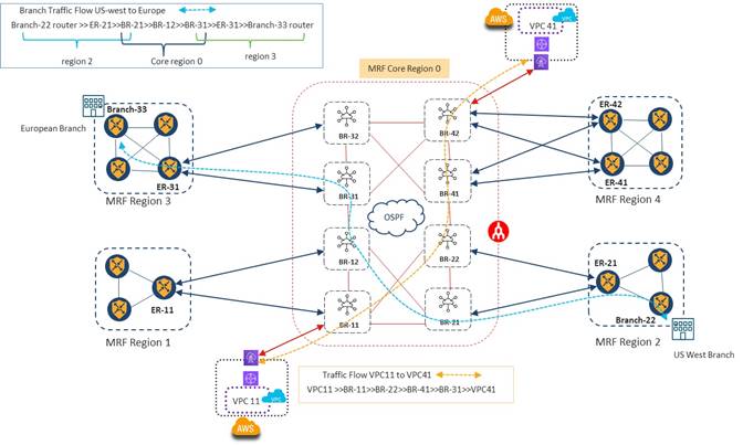
As shown in the figure above, for site-to-site connectivity between US West Branch router Branch-22 and European Branch router Branch-33, traffic will first flow from Branch-22 to Edge Router ER-21 in MRF Region 2 (assuming the alternate connectivity options discussed in the previous section). Edge Router ER-21 has two SD-WAN tunnels – one to Border Router BR-22 and one to Border Router BR-21 in the core region. Traffic can pick either tunnel to reach the core. Hence, in this design Edge Router ER-21 represents an extra router hop between Branch-22 and the Border Routers within the core. This extra hop has the potential of adding additional latency within the network. Additionally, the capacity of Edge Router ER-21 must be such that it can handle all of the inter-region traffic load to and from MRF Region 2, in this design.
In the core region, the OSPF routing protocol in underlay will ensure full-mesh SD-WAN tunnel connectivity between all the Border Routers, even though there is not a full mesh of VXC connections within the core. OSPF metrics can be used to direct traffic within the underlay. In the example in the figure above, traffic will move from Border Router BR-21 to Border Router BR-12 and then from Border Router BR-12 to Border Router BR-31 in the underlay. However, it will use the direct SD-WAN tunnel formed between Border Routers BR-21 and BR-31 in the overlay. Border Router BR-12 represents an extra router hop which has the potential of adding additional latency within the network. Additionally, the capacity of Border Router BR-12 must be such that it can handle all the core traffic load simply passing through it within the core, as well as traffic to and from MRF Region 1.
Edge Router ER-31 has two direct SD-WAN tunnels between Border Routers BR-31 and BR-32. It can pick either SD-WAN tunnel to send traffic into the core region. In MRF Region 3, Edge Router ER-31 will have a direct SD-WAN tunnel to Branch Router BR-33 to send traffic to Europe Branches. However, again Edge Router ER-31 represents an extra router hop between the European Branches in MRF Region 3 and the core. This extra hop has the potential of adding additional latency within the network. Additionally, the capacity of Edge Router ER-31 must be such that it can handle all the Inter-region traffic load to and from MRF Region 3 in this design.
In MRF architecture, Branch router BR-22, Edge Router ER-21 and Border Router BR-12 will be part of MRF region 2. One of interface of BR-21 with biz-internet color will be assigned to MRF region 2. BR-21, BR-12 and BR-31 in this traffic flow will be part of Core region 0. Loopback interface on all these Border Routers will be part of core region with MPLS color. BR-31, ER-31 and Branch-33 will be part of MRF region 3.
Similarly, for site-to-cloud or cloud-to-cloud connectivity, traffic flow can traverse multiple hops in the underlay with the design shown in the figure above, before reaching the final Border Router which is connected to either an Edge Router in an access region or to a VPC/vNet within a public IaaS/PaaS CSP.
Alternatively, when considering the design option of configuring a full-mesh of VXCs in core region, site-to-site inter-region, site-to-cloud, and cloud-to-cloud traffic flows will take less hop counts, as shown in the figure below. Overall, since there is direct connectivity between all Border Router when implementing a full-mesh of VXC connections, the underlay traffic through the core will have to go through less router hops to reach its destination.
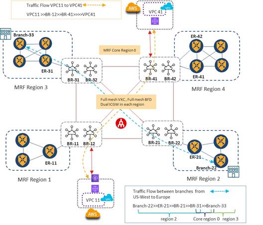
Full mesh VXC connectivity and full mesh SD-WAN tunnels between Border Routers
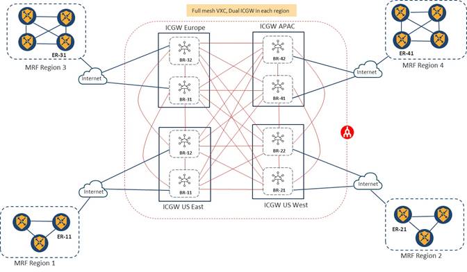
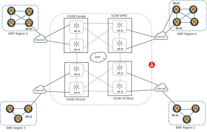
After considering all the options for core region connectivity , 4Dachs2 Consulting decided to go with the design with full-mesh VXC connectivity and dual ICGWs in the core region. Although running a routing protocol in the underlay within the core region was more cost effective in terms of recurring costs since it reduces the number of VXCs significantly, 4Dachs2 Consulting preferred to go with a design with less complexity in the underlay configuration along with direct paths between Border Routers to reduce hop counts. The following figure shows the design with dual Border Router in core for each geographical access region and a full-mesh of VXC connectivity between all Border Routers.
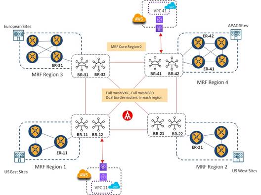
One final area which 4Dachs2 Consulting needed to investigate was redundancy in case of a failure of the SDCI core itself, since the design relies on a single transport within the core. This is discussed in the next section.
MRF SDCI Design with Redundancy and Backup Path
In the most basic Multi-Region Fabric (MRF) design, each device belongs to a single access region.
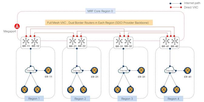
When using Megaport as an SDCI provider with an MRF design, connectivity between Edge Routers and their respective Border Routers is provided by a local Internet circuit. Connectivity between Border Routers is provided by direct VXC connections across the Megaport backbone/fabric.
An Edge Router in Region 1 can connect to an Edge Router in Region 4 by traversing the Core region (Region 0). For example, as shown in the figure below, SD-WAN Edge Router ER-11 can send data to SD-WAN Edge Router ER-41 through the Core (Region 0) by traversing the Border Routers within each of their respective access regions.
Although there are dual Border routers in the Core (Region 0) with this design, there can still be scenarios where connectivity through the Core is lost. For example, both Border routers within a given access region could go down if they were provisioned within the same SDCI PoP. Alternatively, the local ISP connectivity between the Edge Routers and Border Routers within the SDCI PoP could fail, etc.
Dual Edge Routers within the access regions as well as dual links on the Edge Routers to connect to Border Routers, may help in such scenarios. However, the failure of the Border Routers can still remove connectivity of an access region to rest of the access regions of the SD-WAN overlay in this design.
In the example figure below, both Border routers assigned to Region 1 are down or the local Internet connection to the SDCI provider is down. Either scenario can result in loss of connectivity between Region 1 and rest of the regions.
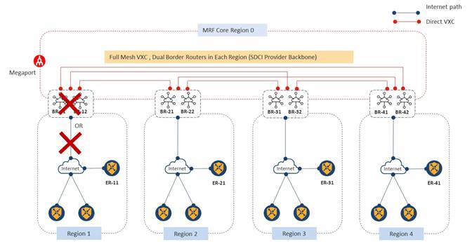
Since 4Dachs2 Consulting already had MPLS circuits on each of their Edge routers within each region, they decided to go with the design of using a secondary region to provide backup via the global MPLS transport, in case of a failure of connectivity between access regions via the Border Routers within the Core.
The use of secondary regions provides another facet to the MRF architecture and enables additional functionality. A secondary region operates more simply than a primary region: it contains only Edge Routers, and it enables direct tunnel connections between Edge routers in different primary regions. When you add a secondary region to an Edge router, the router effectively operates in two access regions simultaneously, and has different paths available through its primary and secondary regions.
4Dachs2 Consulting had the following design options to choose from when using secondary regions:
● Load balance traffic between access regions using the both the path through the SDCI Core and the secondary region path through the MPLS transport.
● Direct only specific applications to use the secondary region path through the MPLS transport, while the rest of the traffic between regions uses the SDCI Core.
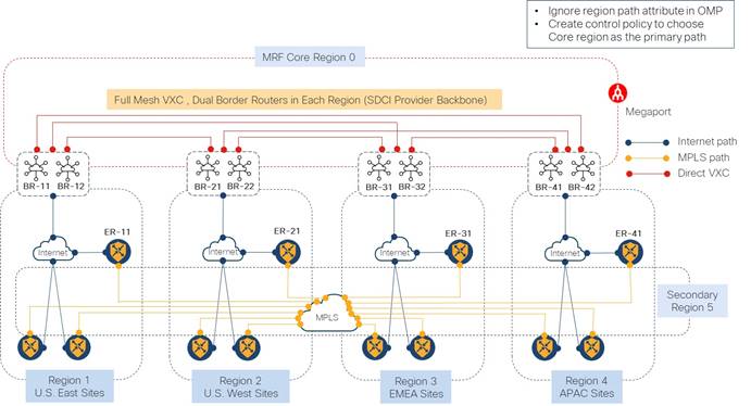
● Use the SDCI Core as the primary path for traffic between access regions; and the secondary region path through the MPLS transport as the backup path for traffic between access regions.
After consideration, 4Dachs2 Consulting decided to use the Core with SDCI transport as the primary path for inter-region connectivity; and the secondary region with the MPLS transport as a backup path.
As shown in the example in the following figure, with a secondary region configuration, the MPLS link between SD-WAN Edge Routers ER-11 and ER-21 can be used as the backup path to provide connectivity between the U.S. East and U.S. West regions (Regions 1 and 2). The primary path for traffic between SD-WAN routers ER-11 and ER-21 will be through the Core (Region 0) using Border Routers.
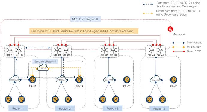
When a direct path is available to reach a destination, by default the Overlay Management Protocol (OMP) enables only the direct path in the routing forwarding layer, because the direct path uses fewer hops. The result is that the forwarding layer, which includes application-aware policy, can only use the direct path. In this design it would result in traffic between SD-WAN Edge Routers ER-11 and ER-21 always going through the direct path of the secondary region, using MPLS transport.
Since 4Dachs2 Consulting wanted the secondary region to be used only as a backup path, they had to configure the SD-WAN routers to ignore the path attribute within OMP. This would disable the comparison of the number of hops so that traffic between SD-WAN Edge Routers ER-11 and ER-21 used the Core region path with more hops, and not secondary-region path with fewer hops. After ignoring the path attribute in OMP, Edge routers will install both routes and will do equal-cost multi-path routing (ECMP) across both the SDCI / Internet link and the MPLS link.
To prefer SDCI / Internet link which connects to the Core (Region 0), 4Dachs2 Consulting had to configure control policy to assign a higher preference to the hierarchical-path through the Core with SDCI / Internet transport, and a lower preference to the direct path via the secondary region and MPLS transport.
Please see Appendix A for an example of the control policy.
Final Design – MRF with SDCI as the Primary Path & MPLS as a Secondary Path
After considering all of the design options discussed in the previous sections, 4Dachs2 Consulting decided to go with an MRF design, using Megaport as the SDCI provider for the backbone to build their Core (Region 0), which would provide the primary path between access regions (Regions 1 through 4).
Since they had a small number of sites within each access region, they chose the option where all Edge Routers connect directly to the Border Routers via a local Internet Service Provider (ISP) within their respective access regions, rather than going through an intermediate Edge Router as discussed previously.
4Dachs2 Consulting also implemented a secondary region (Region 5) on all Edge Routers within all access regions. The secondary region, using the MPLS transport, was configured only as a backup path for providing connectivity between access regions. 4Dachs2 Consulting realized that the use of a secondary region in this manner was not a scalable design. However, they had only a handful of sites within each access region and were not planning to grow much further. Hence scaling issues of using a secondary region in this manner were not a concern.
All Border Routers have full-mesh VXC connections and therefore a full-mesh of SD-WAN tunnels in the Core (Region 0). Since they had a limited number of Edge devices within each access region, 4Dachs2 Consulting also configured a full-mesh of SD-WAN tunnels between Edge routers in the secondary region (Region 5). The MPLS transport was used as the direct path for backup region connectivity between Edge routers.
Example Control Policy for Site-to-Site Connectivity and Traffic Flow
Example Control Policy to Use the Core Region as the Primary Path and Secondary Region as a Backup Path

Appendix B: Changes from Previous Versions
This guide is a new guide. There are no previous versions.
This guide is based upon Cisco SD-WAN software version 17.9/20.9.
AAR Application Aware Routing
AWS Amazon Web Services
BGP Border Gateway Protocol
BR Border Router
CSP Cloud Service Provider
ER Edge Router
IaaS Infrastructure-as-a-Service
ICGW Interconnect Gateway
MVE Megaport Virtual Edge
NVA Network Virtual Appliance
OMP Overlay Management Protocol
OSPF Open Shortest Path First
PaaS Platform-as-a-Service
PoP Point of Presence
SDCI Software-Defined Cloud Interconnect
SLA Service Level Agreement
TGW Transit Gateway
vHub Virtual Hub
vNet Virtual Network
VPC Virtual Private Cloud
vWAN Virtual WAN
VXC Virtual Cross-Connect
WAN Wide Area Network
For comments and suggestions about this guide and related guides, join the discussion on Cisco Community at https://cs.co/en-cvds.