-
null
Configuring Interface Characteristics
This chapter defines the types of interfaces on the switch and describes how to configure them. Unless otherwise noted, the term switch refers to a standalone switch and to a switch stack.
The chapter consists of these sections:
•![]() Understanding Interface Types
Understanding Interface Types
•![]() Using Interface Configuration Mode
Using Interface Configuration Mode
•![]() Using the Internal Ethernet Management Port
Using the Internal Ethernet Management Port
•![]() Configuring Ethernet Interfaces
Configuring Ethernet Interfaces
•![]() Configuring Layer 3 Interfaces
Configuring Layer 3 Interfaces
•![]() Monitoring and Maintaining the Interfaces
Monitoring and Maintaining the Interfaces

Note ![]() For complete syntax and usage information for the commands used in this chapter, see the switch command reference for this release and the online Cisco IOS Interface Command Reference, Release 12.2.
For complete syntax and usage information for the commands used in this chapter, see the switch command reference for this release and the online Cisco IOS Interface Command Reference, Release 12.2.
Understanding Interface Types
This section describes the different types of interfaces supported by the switch with references to chapters that contain more detailed information about configuring these interface types. The rest of the chapter describes configuration procedures for physical interface characteristics.
Note ![]() The stack ports on the front of the switch are not Ethernet ports and cannot be configured.
The stack ports on the front of the switch are not Ethernet ports and cannot be configured.
These sections describe the interface types:
•![]() 10-Gigabit Ethernet Interfaces
10-Gigabit Ethernet Interfaces
Port-Based VLANs
A VLAN is a switched network that is logically segmented by function, team, or application, without regard to the physical location of the users. For more information about VLANs, see Chapter 13 "Configuring VLANs." Packets received on a port are forwarded only to ports that belong to the same VLAN as the receiving port. Network devices in different VLANs cannot communicate with one another without a Layer 3 device to route traffic between the VLANs.
VLAN partitions provide hard firewalls for traffic in the VLAN, and each VLAN has its own MAC address table. A VLAN comes into existence when a local port is configured to be associated with the VLAN, when the VLAN Trunking Protocol (VTP) learns of its existence from a neighbor on a trunk, or when a user creates a VLAN. VLANs can be formed with ports across the stack.
To configure VLANs, use the vlan vlan-id global configuration command to enter VLAN configuration mode. The VLAN configurations for normal-range VLANs (VLAN IDs 1 to 1005) are saved in the VLAN database. If VTP is version 1 or 2, to configure extended-range VLANs (VLAN IDs 1006 to 4094), you must first set VTP mode to transparent. Extended-range VLANs created in transparent mode are not added to the VLAN database but are saved in the switch running configuration. With VTP version 3, you can create extended-range VLANs in client or server mode. These VLANs are saved in the VLAN database.
In a switch stack, the VLAN database is downloaded to all switches in a stack, and all switches in the stack build the same VLAN database. In a switch stack, the running configuration and the saved configuration are the same for all switches in a stack.
Add ports to a VLAN by using the switchport interface configuration commands:
•![]() Identify the interface.
Identify the interface.
•![]() For a trunk port, set trunk characteristics, and, if desired, define the VLANs to which it can belong.
For a trunk port, set trunk characteristics, and, if desired, define the VLANs to which it can belong.
•![]() For an access port, set and define the VLAN to which it belongs.
For an access port, set and define the VLAN to which it belongs.
•![]() For a tunnel port, set and define the VLAN ID for the customer-specific VLAN tag. See Chapter 17 "Configuring IEEE 802.1Q and Layer 2 Protocol Tunneling."
For a tunnel port, set and define the VLAN ID for the customer-specific VLAN tag. See Chapter 17 "Configuring IEEE 802.1Q and Layer 2 Protocol Tunneling."
Switch Ports
Switch ports are Layer 2-only interfaces associated with a physical port. Switch ports belong to one or more VLANs. A switch port can be an access port, a trunk port, or a tunnel port. You can configure a port as an access port or trunk port or let the Dynamic Trunking Protocol (DTP) operate on a per-port basis to set the switchport mode by negotiating with the port on the other end of the link. You must manually configure tunnel ports as part of an asymmetric link connected to an IEEE 802.1Q trunk port. Switch ports are used for managing the physical interface and associated Layer 2 protocols and do not handle routing or bridging.
Configure switch ports by using the switchport interface configuration commands. Use the switchport command with no keywords to put an interface that is in Layer 3 mode into Layer 2 mode.
Note ![]() When you put an interface that is in Layer 3 mode into Layer 2 mode, the previous configuration information related to the affected interface might be lost, and the interface is returned to its default configuration.
When you put an interface that is in Layer 3 mode into Layer 2 mode, the previous configuration information related to the affected interface might be lost, and the interface is returned to its default configuration.
For detailed information about configuring access port and trunk port characteristics, see Chapter 13 "Configuring VLANs." For more information about tunnel ports, see Chapter 17 "Configuring IEEE 802.1Q and Layer 2 Protocol Tunneling."
Access Ports
An access port belongs to and carries the traffic of only one VLAN (unless it is configured as a voice VLAN port). Traffic is received and sent in native formats with no VLAN tagging. Traffic arriving on an access port is assumed to belong to the VLAN assigned to the port. If an access port receives an IEEE 802.1Q tagged packet), the packet is dropped, and the source address is not learned.
Two types of access ports are supported:
•![]() Static access ports are manually assigned to a VLAN (or through a RADIUS server for use with IEEE 802.1x. For more information, see the "802.1x Authentication with VLAN Assignment" section.)
Static access ports are manually assigned to a VLAN (or through a RADIUS server for use with IEEE 802.1x. For more information, see the "802.1x Authentication with VLAN Assignment" section.)
•![]() VLAN membership of dynamic access ports is learned through incoming packets. By default, a dynamic access port is not a member of any VLAN, and forwarding to and from the port is enabled only when the VLAN membership of the port is discovered. Dynamic access ports on the switch are assigned to a VLAN by a VLAN Membership Policy Server (VMPS). The VMPS can be a Catalyst 6500 series switch; the switch cannot be a VMPS server.
VLAN membership of dynamic access ports is learned through incoming packets. By default, a dynamic access port is not a member of any VLAN, and forwarding to and from the port is enabled only when the VLAN membership of the port is discovered. Dynamic access ports on the switch are assigned to a VLAN by a VLAN Membership Policy Server (VMPS). The VMPS can be a Catalyst 6500 series switch; the switch cannot be a VMPS server.
You can also configure an access port with an attached Cisco IP Phone to use one VLAN for voice traffic and another VLAN for data traffic from a device attached to the phone. For more information about voice VLAN ports, see Chapter 15 "Configuring Voice VLAN."
Trunk Ports
A trunk port carries the traffic of multiple VLANs and by default is a member of all VLANs in the VLAN database. An IEEE 802.1Q trunk port supports simultaneous tagged and untagged traffic. An IEEE 802.1Q trunk port is assigned a default port VLAN ID (PVID), and all untagged traffic travels on the port default PVID. All untagged traffic and tagged traffic with a NULL VLAN ID are assumed to belong to the port default PVID. A packet with a VLAN ID equal to the outgoing port default PVID is sent untagged. All other traffic is sent with a VLAN tag.
Although by default, a trunk port is a member of every VLAN known to the VTP, you can limit VLAN membership by configuring an allowed list of VLANs for each trunk port. The list of allowed VLANs does not affect any other port but the associated trunk port. By default, all possible VLANs (VLAN ID 1 to 4094) are in the allowed list. A trunk port can become a member of a VLAN only if VTP knows of the VLAN and if the VLAN is in the enabled state. If VTP learns of a new, enabled VLAN and the VLAN is in the allowed list for a trunk port, the trunk port automatically becomes a member of that VLAN and traffic is forwarded to and from the trunk port for that VLAN. If VTP learns of a new, enabled VLAN that is not in the allowed list for a trunk port, the port does not become a member of the VLAN, and no traffic for the VLAN is forwarded to or from the port.
For more information about trunk ports, see Chapter 13 "Configuring VLANs."
Tunnel Ports
Tunnel ports are used in IEEE 802.1Q tunneling to segregate the traffic of customers in a service-provider network from other customers who are using the same VLAN number. You configure an asymmetric link from a tunnel port on a service-provider edge switch to an IEEE 802.1Q trunk port on the customer switch. Packets entering the tunnel port on the edge switch, already IEEE 802.1Q-tagged with the customer VLANs, are encapsulated with another layer of an IEEE 802.1Q tag (called the metro tag), containing a VLAN ID unique in the service-provider network, for each customer. The double-tagged packets go through the service-provider network keeping the original customer VLANs separate from those of other customers. At the outbound interface, also a tunnel port, the metro tag is removed, and the original VLAN numbers from the customer network are retrieved.
Tunnel ports cannot be trunk ports or access ports and must belong to a VLAN unique to each customer.
For more information about tunnel ports, see Chapter 17 "Configuring IEEE 802.1Q and Layer 2 Protocol Tunneling."
Routed Ports
A routed port is a physical port that acts like a port on a router; it does not have to be connected to a router. A routed port is not associated with a particular VLAN, as is an access port. A routed port behaves like a regular router interface, except that it does not support VLAN subinterfaces. Routed ports can be configured with a Layer 3 routing protocol. A routed port is a Layer 3 interface only and does not support Layer 2 protocols, such as DTP and STP.
Configure routed ports by putting the interface into Layer 3 mode with the no switchport interface configuration command. Then assign an IP address to the port, enable routing, and assign routing protocol characteristics by using the ip routing and router protocol global configuration commands.
Note ![]() Entering a no switchport interface configuration command shuts down the interface and then re-enables it, which might generate messages on the device to which the interface is connected. When you put an interface that is in Layer 2 mode into Layer 3 mode, the previous configuration information related to the affected interface might be lost.
Entering a no switchport interface configuration command shuts down the interface and then re-enables it, which might generate messages on the device to which the interface is connected. When you put an interface that is in Layer 2 mode into Layer 3 mode, the previous configuration information related to the affected interface might be lost.
The number of routed ports that you can configure is not limited by software. However, the interrelationship between this number and the number of other features being configured might impact CPU performance because of hardware limitations. See the "Configuring Layer 3 Interfaces" section for information about what happens when hardware resource limitations are reached.
For more information about IP unicast and multicast routing and routing protocols, see Chapter 39 "Configuring IP Unicast Routing" and Chapter 45 "Configuring IP Multicast Routing."
Note ![]() The IP base feature set supports static routing and the Routing Information Protocol (RIP). For full Layer 3 routing or for fallback bridging, you must enable the IP services feature set on the standalone switch, or the stack master.
The IP base feature set supports static routing and the Routing Information Protocol (RIP). For full Layer 3 routing or for fallback bridging, you must enable the IP services feature set on the standalone switch, or the stack master.
Hidden Interfaces
GigabitEthernet ports x/0/19 and x/0/20 in the Catalyst Module Switch 3110 and GigabitEthernet ports 0/19 and 0/20 in the Catalyst Module Switch 3012 are internal ports (hidden interfaces) used for communication with the Advanced management Module (aMM). However, the port can appear in some CLI command outputs such as the show cdp neighbors privileged EXEC command, and some port configuration can appear in the output of the show running-config privileged EXEC command.
This is an example of a line in the show running-config output referring to one of these ports:
mac address-table static 001e.xxxx.xxxx vlan 1002 interface GigabitEthernet1/0/19
Do not try to configure these interfaces or change the configuration in the running configuration or startup configuration.
Switch Virtual Interfaces
A switch virtual interface (SVI) represents a VLAN of switch ports as one interface to the routing or bridging function in the system. Only one SVI can be associated with a VLAN, but you need to configure an SVI for a VLAN only when you wish to route between VLANs, to fallback-bridge nonroutable protocols between VLANs, or to provide IP host connectivity to the switch. By default, an SVI is created for the default VLAN (VLAN 1) to permit remote switch administration. Additional SVIs must be explicitly configured.
Note ![]() You cannot delete interface VLAN 1.
You cannot delete interface VLAN 1.
SVIs provide IP host connectivity only to the system; in Layer 3 mode, you can configure routing across SVIs.
Although the switch stack or switch supports a total of 1005 VLANs (and SVIs), the interrelationship between the number of SVIs and routed ports and the number of other features being configured might impact CPU performance because of hardware limitations. See the "Configuring Layer 3 Interfaces" section for information about what happens when hardware resource limitations are reached.
SVIs are created the first time that you enter the vlan interface configuration command for a VLAN interface. The VLAN corresponds to the VLAN tag associated with data frames on an 802.1Q encapsulated trunk or the VLAN ID configured for an access port. Configure a VLAN interface for each VLAN for which you want to route traffic, and assign it an IP address. For more information, see the "Manually Assigning IP Information" section.
Note ![]() When you create an SVI, it does not become active until it is associated with a physical port.
When you create an SVI, it does not become active until it is associated with a physical port.
SVIs support routing protocols and bridging configurations. For more information about configuring IP routing, see Chapter 39 "Configuring IP Unicast Routing," Chapter 45 "Configuring IP Multicast Routing,"and Chapter 47 "Configuring Fallback Bridging."
Note ![]() The IP base feature set supports static routing and RIP. For more advanced routing or for fallback bridging, enable the IP services feature set on standalone switch, or the stack master.
The IP base feature set supports static routing and RIP. For more advanced routing or for fallback bridging, enable the IP services feature set on standalone switch, or the stack master.
SVI Autostate Exclude
The line state of an SVI with multiple ports on a VLAN is in the up state when it meets these conditions:
•![]() The VLAN exists and is active in the VLAN database on the switch.
The VLAN exists and is active in the VLAN database on the switch.
•![]() The VLAN interface exists and is not administratively down.
The VLAN interface exists and is not administratively down.
•![]() At least one Layer 2 (access or trunk) port exists, has a link in the up state on this VLAN, and is in the spanning-tree forwarding state on the VLAN.
At least one Layer 2 (access or trunk) port exists, has a link in the up state on this VLAN, and is in the spanning-tree forwarding state on the VLAN.
Note ![]() The protocol link state for VLAN interfaces come up when the first switchport belonging to the corresponding VLAN link comes up and is in STP forwarding state.
The protocol link state for VLAN interfaces come up when the first switchport belonging to the corresponding VLAN link comes up and is in STP forwarding state.
The default action, when a VLAN has multiple ports, is that the SVI goes down when all ports in the VLAN go down. You can use the SVI autostate exclude feature to configure a port so that it is not included in the SVI line-state up-an- down calculation. For example, if the only active port on the VLAN is a monitoring port, you might configure autostate exclude on that port so that the VLAN goes down when all other ports go down. When enabled on a port, autostate exclude applies to all VLANs that are enabled on that port.
The VLAN interface is brought up when one Layer 2 port in the VLAN has had time to converge (transition from STP listening-learning state to forwarding state). This prevents features such as routing protocols from using the VLAN interface as if it were fully operational and minimizes other problems, such as routing black holes. For information about configuring autostate exclude, see the "Configuring SVI Autostate Exclude" section.
EtherChannel Port Groups
EtherChannel port groups treat multiple switch ports as one switch port. These port groups act as a single logical port for high-bandwidth connections between switches or between switches and servers. An EtherChannel balances the traffic load across the links in the channel. If a link within the EtherChannel fails, traffic previously carried over the failed link changes to the remaining links. You can group multiple trunk ports into one logical trunk port, group multiple access ports into one logical access port, group multiple tunnel ports into one logical tunnel port, or group multiple routed ports into one logical routed port. Most protocols operate over either single ports or aggregated switch ports and do not recognize the physical ports within the port group. Exceptions are the DTP, the Cisco Discovery Protocol (CDP), and the Port Aggregation Protocol (PAgP), which operate only on physical ports.
When you configure an EtherChannel, you create a port-channel logical interface and assign an interface to the EtherChannel. For Layer 3 interfaces, you manually create the logical interface by using the interface port-channel global configuration command. Then you manually assign an interface to the EtherChannel by using the channel-group interface configuration command. For Layer 2 interfaces, use the channel-group interface configuration command to dynamically create the port-channel logical interface. This command binds the physical and logical ports together. For more information, see Chapter 38 "Configuring EtherChannels and Link-State Tracking."
10-Gigabit Ethernet Interfaces
The switch has one 10-Gigabit Ethernet module slot.
A 10-Gigabit Ethernet interface operates only in full-duplex mode. The interface can be configured as a switched or routed port.
Connecting Interfaces
Devices within a single VLAN can communicate directly through any switch. Ports in different VLANs cannot exchange data without going through a routing device. With a standard Layer 2 switch, ports in different VLANs have to exchange information through a router.
By using the switch with routing enabled, when you configure both VLAN 20 and VLAN 30 with an SVI to which an IP address is assigned, packets can be sent from Blade Server A to Blade Server B directly through the switch with no need for an external router (Figure 11-1).
Figure 11-1 Connecting VLANs with the Blade Switch
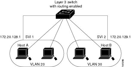
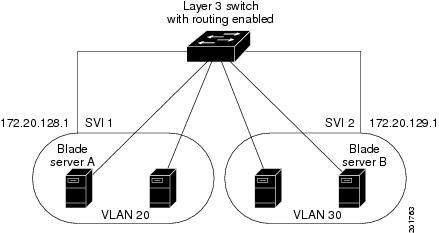
When the IP services feature set is running on the switch or the stack master, the switch uses two methods to forward traffic between interfaces: routing and fallback bridging. If the IP base feature set is on the switch or the stack master, only basic routing (static routing and RIP) is supported. Whenever possible, to maintain high performance, forwarding is done by the switch hardware. However, only IPv4 packets with Ethernet II encapsulation are routed in hardware. Non-IP traffic and traffic with other encapsulation methods are fallback-bridged by hardware.
•![]() The routing function can be enabled on all SVIs and routed ports. The switch routes only IP traffic. When IP routing protocol parameters and address configuration are added to an SVI or routed port, any IP traffic received from these ports is routed. For more information, see Chapter 39 "Configuring IP Unicast Routing," Chapter 45 "Configuring IP Multicast Routing," and Chapter 46 "Configuring MSDP."
The routing function can be enabled on all SVIs and routed ports. The switch routes only IP traffic. When IP routing protocol parameters and address configuration are added to an SVI or routed port, any IP traffic received from these ports is routed. For more information, see Chapter 39 "Configuring IP Unicast Routing," Chapter 45 "Configuring IP Multicast Routing," and Chapter 46 "Configuring MSDP."
•![]() Fallback bridging forwards traffic that the switch does not route or traffic belonging to a nonroutable protocol, such as DECnet. Fallback bridging connects multiple VLANs into one bridge domain by bridging between two or more SVIs or routed ports. When configuring fallback bridging, you assign SVIs or routed ports to bridge groups with each SVI or routed port assigned to only one bridge group. All interfaces in the same group belong to the same bridge domain. For more information, see Chapter 47 "Configuring Fallback Bridging."
Fallback bridging forwards traffic that the switch does not route or traffic belonging to a nonroutable protocol, such as DECnet. Fallback bridging connects multiple VLANs into one bridge domain by bridging between two or more SVIs or routed ports. When configuring fallback bridging, you assign SVIs or routed ports to bridge groups with each SVI or routed port assigned to only one bridge group. All interfaces in the same group belong to the same bridge domain. For more information, see Chapter 47 "Configuring Fallback Bridging."
Using Interface Configuration Mode
The switch supports these interface types:
•![]() Physical ports—switch ports and routed ports
Physical ports—switch ports and routed ports
•![]() VLANs—switch virtual interfaces
VLANs—switch virtual interfaces
•![]() Port channels—EtherChannel interfaces
Port channels—EtherChannel interfaces
You can also configure a range of interfaces (see the "Configuring a Range of Interfaces" section).
To configure a physical interface (port), specify the interface type, stack member number, module number, and switch port number, and enter interface configuration mode.
•![]() Type—Gigabit Ethernet (gigabitethernet or gi) for 10/100/1000 Mb/s Ethernet ports or 10-Gigabit Ethernet (tengigabitethernet or te) for 10,000 Mb/s.
Type—Gigabit Ethernet (gigabitethernet or gi) for 10/100/1000 Mb/s Ethernet ports or 10-Gigabit Ethernet (tengigabitethernet or te) for 10,000 Mb/s.
•![]() Stack member number—The number that identifies the switch within the stack. The switch number range is 1 to 9 and is assigned the first time the switch initializes. The default switch number, before it is integrated into a switch stack, is 1. When a switch has been assigned a stack member number, it keeps that number until another is assigned to it.
Stack member number—The number that identifies the switch within the stack. The switch number range is 1 to 9 and is assigned the first time the switch initializes. The default switch number, before it is integrated into a switch stack, is 1. When a switch has been assigned a stack member number, it keeps that number until another is assigned to it.
You can use the switch port LEDs in Stack mode to identify the stack member number of a switch.
For information about stack member numbers, see the "Stack Member Numbers" section.
•![]() Module number—The module or slot number on the switch that is always 0.
Module number—The module or slot number on the switch that is always 0.
•![]() Port number—The interface number on the switch.
Port number—The interface number on the switch.
These are the port numbers on the Catalyst Module Switch 3110X:
–![]() The internal 1000 Mb/s ports are numbered consecutively from 1 to 14; for example, gigabitethernet 1/0/1.
The internal 1000 Mb/s ports are numbered consecutively from 1 to 14; for example, gigabitethernet 1/0/1.
–![]() When a Cisco X2 transceiver module is in the 10-Gigabit Ethernet module slot, the port number is 1; for example, tengigabitethernet1/0/1.
When a Cisco X2 transceiver module is in the 10-Gigabit Ethernet module slot, the port number is 1; for example, tengigabitethernet1/0/1.
These are the port numbers on the Catalyst Switch Module 3110G:
–![]() The internal 1000 Mb/s ports are numbered consecutively from 1 to 14; for example, gigabitethernet 1/0/1.
The internal 1000 Mb/s ports are numbered consecutively from 1 to 14; for example, gigabitethernet 1/0/1.
–![]() On a switch with four external 10/100/1000 ports, the external 10/100/1000 port numbers are numbered from 15 to 18; for example, gigabitethernet1/0/16.
On a switch with four external 10/100/1000 ports, the external 10/100/1000 port numbers are numbered from 15 to 18; for example, gigabitethernet1/0/16.
These are the port numbers on a Catalyst Switch Module 3012 with 12 internal 1000 Mb/s ports and 4 external 10/100/1000 ports:
–![]() The internal ports are numbered consecutively from 1 to 12; for example, gigabitethernet 0/3.
The internal ports are numbered consecutively from 1 to 12; for example, gigabitethernet 0/3.
–![]() The external ports are numbered consecutively from 13 to 16; for example, gigabitethernet0/15.
The external ports are numbered consecutively from 13 to 16; for example, gigabitethernet0/15.
You can identify physical interfaces by physically checking the interface location on the switch. You can also use the show privileged EXEC commands to display information about a specific interface or all the interfaces on the switch. The remainder of this chapter primarily provides physical interface configuration procedures.
These are examples of how to identify interfaces on a switch:
•![]() To configure 10/100/1000 port 4 on a standalone switch, enter this command:
To configure 10/100/1000 port 4 on a standalone switch, enter this command:
Switch(config)# interface gigabitethernet1/0/4
•![]() To configure 10-Gigabit Ethernet port 1 on a standalone switch, enter this command:
To configure 10-Gigabit Ethernet port 1 on a standalone switch, enter this command:
Switch(config)# interface tengigabitethernet1/0/1
•![]() To configure 10-Gigabit Ethernet port on stack member 3, enter this command:
To configure 10-Gigabit Ethernet port on stack member 3, enter this command:
Switch(config)# interface tengigabitethernet3/0/1
Procedures for Configuring Interfaces
These general instructions apply to all interface configuration processes.
Step 1 ![]() Enter the configure terminal command at the privileged EXEC prompt:
Enter the configure terminal command at the privileged EXEC prompt:
Switch# configure terminal
Enter configuration commands, one per line. End with CNTL/Z.
Switch(config)#
Step 2 ![]() Enter the interface global configuration command. Identify the interface type, the switch number, and the number of the connector. In this example, Gigabit Ethernet port 1 on switch 1 is selected:
Enter the interface global configuration command. Identify the interface type, the switch number, and the number of the connector. In this example, Gigabit Ethernet port 1 on switch 1 is selected:
Switch(config)# interface gigabitethernet1/0/1
Switch(config-if)#
Note ![]() You do not need to add a space between the interface type and the interface number. For example, in the preceding line, you can specify either gigabitethernet 1/0/1, gigabitethernet1/0/1, gi 1/0/1, or gi1/0/1.
You do not need to add a space between the interface type and the interface number. For example, in the preceding line, you can specify either gigabitethernet 1/0/1, gigabitethernet1/0/1, gi 1/0/1, or gi1/0/1.
Step 3 ![]() Follow each interface command with the interface configuration commands that the interface requires. The commands that you enter define the protocols and applications that will run on the interface. The commands are collected and applied to the interface when you enter another interface command or enter end to return to privileged EXEC mode.
Follow each interface command with the interface configuration commands that the interface requires. The commands that you enter define the protocols and applications that will run on the interface. The commands are collected and applied to the interface when you enter another interface command or enter end to return to privileged EXEC mode.
You can also configure a range of interfaces by using the interface range or interface range macro global configuration commands. Interfaces configured in a range must be the same type and must be configured with the same feature options.
Step 4 ![]() After you configure an interface, verify its status by using the show privileged EXEC commands listed in the "Monitoring and Maintaining the Interfaces" section.
After you configure an interface, verify its status by using the show privileged EXEC commands listed in the "Monitoring and Maintaining the Interfaces" section.
Enter the show interfaces privileged EXEC command to see a list of all interfaces on or configured for the switch. A report is provided for each interface that the device supports or for the specified interface.
Configuring a Range of Interfaces
You can use the interface range global configuration command to configure multiple interfaces with the same configuration parameters. When you enter the interface-range configuration mode, all command parameters that you enter are attributed to all interfaces within that range until you exit this mode.
Beginning in privileged EXEC mode, follow these steps to configure a range of interfaces with the same parameters:
|
|
|
|
|---|---|---|
Step 1 |
configure terminal |
Enter global configuration mode. |
Step 2 |
interface range {port-range | macro macro_name} |
Specify the range of interfaces (VLANs or physical ports) to be configured, and enter interface-range configuration mode. • • • • |
Step 3 |
Use the normal configuration commands to apply the configuration parameters to all interfaces in the range. Each command is executed as it is entered. |
|
Step 4 |
end |
Return to privileged EXEC mode. |
Step 5 |
show interfaces [interface-id] |
Verify the configuration of the interfaces in the range. |
Step 6 |
copy running-config startup-config |
(Optional) Save your entries in the configuration file. |
When using the interface range global configuration command, note these guidelines:
•![]() Valid entries for port-range:
Valid entries for port-range:
–![]() vlan vlan-ID - vlan-ID, where the VLAN ID is 1 to 4094
vlan vlan-ID - vlan-ID, where the VLAN ID is 1 to 4094
–![]() gigabitethernet module/{first port} - {last port}, where the module is always 0 (for nonstacking-capable switches)
gigabitethernet module/{first port} - {last port}, where the module is always 0 (for nonstacking-capable switches)
gigabitethernet stack member/module/{first port} - {last port}, where the module is always 0 (for stacking-capable switches)
–![]() tengigabitethernet module/{first port} - {last port}, where the module is always 0 (for nonstacking-capable switches)
tengigabitethernet module/{first port} - {last port}, where the module is always 0 (for nonstacking-capable switches)
tengigabitethernet stack member/module/{first port} - {last port}, where the module is always 0 (for stacking-capable switches)
–![]() port-channel port-channel-number - port-channel-number, where the port-channel-number is 1 to 64
port-channel port-channel-number - port-channel-number, where the port-channel-number is 1 to 64
Note ![]() When you use the interface range command with port channels, the first and last port-channel number must be active port channels.
When you use the interface range command with port channels, the first and last port-channel number must be active port channels.
•![]() You must add a space between the first interface number and the hyphen when using the interface range command. For example, the command interface range gigabitethernet1/0/1 - 4 is a valid range; the command interface range gigabitethernet1/0/1-4 is not a valid range.
You must add a space between the first interface number and the hyphen when using the interface range command. For example, the command interface range gigabitethernet1/0/1 - 4 is a valid range; the command interface range gigabitethernet1/0/1-4 is not a valid range.
•![]() The interface range command only works with VLAN interfaces that have been configured with the interface vlan command. The show running-config privileged EXEC command displays the configured VLAN interfaces. VLAN interfaces not displayed by the show running-config command cannot be used with the interface range command.
The interface range command only works with VLAN interfaces that have been configured with the interface vlan command. The show running-config privileged EXEC command displays the configured VLAN interfaces. VLAN interfaces not displayed by the show running-config command cannot be used with the interface range command.
•![]() All interfaces defined in a range must be the same type (all Gigabit Ethernet ports, all 10-Gigabit Ethernet ports, all EtherChannel ports, or all VLANs), but you can enter multiple ranges in a command.
All interfaces defined in a range must be the same type (all Gigabit Ethernet ports, all 10-Gigabit Ethernet ports, all EtherChannel ports, or all VLANs), but you can enter multiple ranges in a command.
This example shows how to use the interface range global configuration command to set the speed
to 100 Mb/s on ports 1 to 4 on switch 1:
Switch# configure terminal
Switch(config)# interface range gigabitethernet1/0/19 - 20
Switch(config-if-range)# speed 100
This example shows how to use a comma to add different interface type strings to the range to enable Gigabit Ethernet ports 1 to 3 and 10-Gigabit Ethernet ports 1 and 2 to receive flow-control pause frames:
Switch# configure terminal
Switch(config)# interface range gigabitethernet1/0/1 - 3 , tengigabitethernet1/0/1 - 2
Switch(config-if-range)# flowcontrol receive on
If you enter multiple configuration commands while you are in interface-range mode, each command is executed as it is entered. The commands are not batched and executed after you exit interface-range mode. If you exit interface-range configuration mode while the commands are being executed, some commands might not be executed on all interfaces in the range. Wait until the command prompt reappears before exiting interface-range configuration mode.
Configuring and Using Interface Range Macros
You can create an interface range macro to automatically select a range of interfaces for configuration. Before you can use the macro keyword in the interface range macro global configuration command string, you must use the define interface-range global configuration command to define the macro.
Beginning in privileged EXEC mode, follow these steps to define an interface range macro:
Use the no define interface-range macro_name global configuration command to delete a macro.
When using the define interface-range global configuration command, note these guidelines:
•![]() Valid entries for interface-range:
Valid entries for interface-range:
–![]() vlan vlan-ID - vlan-ID, where the VLAN ID is 1 to 4094
vlan vlan-ID - vlan-ID, where the VLAN ID is 1 to 4094
–![]() gigabitethernet module/{first port} - {last port}, where the module is always 0 (for nonstacking-capable switches)
gigabitethernet module/{first port} - {last port}, where the module is always 0 (for nonstacking-capable switches)
gigabitethernet stack member/module/{first port} - {last port}, where the module is always 0 (for stacking-capable switches)
–![]() tengigabitethernet module/{first port} - {last port}, where the module is always 0 (for nonstacking-capable switches)
tengigabitethernet module/{first port} - {last port}, where the module is always 0 (for nonstacking-capable switches)
tengigabitethernet stack member/module/{first port} - {last port}, where the module is always 0 (for stacking-capable switches)
–![]() port-channel port-channel-number - port-channel-number, where the port-channel-number is 1 to 64.
port-channel port-channel-number - port-channel-number, where the port-channel-number is 1 to 64.
Note ![]() When you use the interface ranges with port channels, the first and last port-channel number must be active port channels.
When you use the interface ranges with port channels, the first and last port-channel number must be active port channels.
•![]() You must add a space between the first interface number and the hyphen when entering an interface-range. For example, gigabitethernet1/0/1 - 4 is a valid range; gigabitethernet1/0/1-4 is not a valid range.
You must add a space between the first interface number and the hyphen when entering an interface-range. For example, gigabitethernet1/0/1 - 4 is a valid range; gigabitethernet1/0/1-4 is not a valid range.
•![]() The VLAN interfaces must have been configured with the interface vlan command. The show running-config privileged EXEC command displays the configured VLAN interfaces. VLAN interfaces not displayed by the show running-config command cannot be used as interface-ranges.
The VLAN interfaces must have been configured with the interface vlan command. The show running-config privileged EXEC command displays the configured VLAN interfaces. VLAN interfaces not displayed by the show running-config command cannot be used as interface-ranges.
•![]() All interfaces defined as in a range must be the same type (all Gigabit Ethernet ports, all 10-Gigabit Ethernet ports, all EtherChannel ports, or all VLANs), but you can combine multiple interface types in a macro.
All interfaces defined as in a range must be the same type (all Gigabit Ethernet ports, all 10-Gigabit Ethernet ports, all EtherChannel ports, or all VLANs), but you can combine multiple interface types in a macro.
This example shows how to define an interface-range named enet_list to include ports 1 and 2 on switch 1 and to verify the macro configuration:
Switch# configure terminal
Switch(config)# define interface-range enet_list gigabitethernet1/0/1 - 2
Switch(config)# end
Switch# show running-config | include define
define interface-range enet_list GigabitEthernet1/0/1 - 2
This example shows how to create a multiple-interface macro named macro1:
Switch# configure terminal
Switch(config)# define interface-range macro1 gigabitethernet1/0/1 - 2,
gigabitethernet1/0/5 - 7, tengigabitethernet1/0/1 -2
Switch(config)# end
This example shows how to enter interface-range configuration mode for the interface-range macro enet_list:
Switch# configure terminal
Switch(config)# interface range macro enet_list
Switch(config-if-range)#
This example shows how to delete the interface-range macro enet_list and to verify that it was deleted.
Switch# configure terminal
Switch(config)# no define interface-range enet_list
Switch(config)# end
Switch# show run | include define
Switch#
Using the Internal Ethernet Management Port
This section has this information:
•![]() Understanding the Internal Ethernet Management Port
Understanding the Internal Ethernet Management Port
•![]() Supported Features on the Ethernet Management Port
Supported Features on the Ethernet Management Port
•![]() Layer 3 Routing Configuration Guidelines
Layer 3 Routing Configuration Guidelines
•![]() Monitoring the Ethernet Management Port
Monitoring the Ethernet Management Port
Understanding the Internal Ethernet Management Port
The internal Ethernet management port, also referred to as the Fa0 or fastethernet0 port, is an internal Layer 3 port connected to the Advanced Managment Module (AMM) (see Figure 11-2). You assign the IP addresses to the internal Ethernet management port through the AMM of a standalone switch. You can manage the switch through this IP address.
On a standalone switch, the internal Ethernet management port is always enabled (up) and cannot be shut down. The port is always disabled when the switch is a stack member.
You cannot change the IP address of a stack member by using the AMM. For a nonstacking-capable switch or a standalone stacking-capable switch, connect the AMM Ethernet management port to the PC as shown in Figure 11-2.
Figure 11-2 Connecting a Switch to a PC

|
|
AMM |
|
|
Internal Ethernet management port |
Figure 11-3 shows how to connect a switch stack to the PC. The PC does not have to be connected to the stack master.
Figure 11-3 Connecting a Switch Stack to a PC

By default, the Ethernet management port is enabled on a standalone switch. The switch cannot route packets from the Ethernet management port to a network port and the reverse.
Supported Features on the Ethernet Management Port
On a standalone switch, the Ethernet management port is enabled and supports only these features:
•![]() Network Assistant
Network Assistant
•![]() Telnet with passwords
Telnet with passwords
•![]() TFTP
TFTP
•![]() Secure Shell (SSH)
Secure Shell (SSH)
•![]() DHCP-based autoconfiguration
DHCP-based autoconfiguration
•![]() SMNP (only the ENTITY-MIB and the IF-MIB)
SMNP (only the ENTITY-MIB and the IF-MIB)
•![]() IP ping
IP ping
•![]() Interface features
Interface features
–![]() Speed—100 Mb/s (nonconfigurable)
Speed—100 Mb/s (nonconfigurable)
–![]() Duplex mode—Full (nonconfigurable)
Duplex mode—Full (nonconfigurable)
–![]() Loopback detection
Loopback detection
•![]() IPv4 and IPv6 access control lists (ACLs)
IPv4 and IPv6 access control lists (ACLs)

Layer 3 Routing Configuration Guidelines
When Layer 3 routing is enabled, you should be aware of these guidelines:
•![]() If Routing Information Protocol (RIP) or Open Shortest Path First (OSPF) is enabled, RIP or OSPF advertises routes with the internal Ethernet management port. By default, RIP and OSPF are disabled.
If Routing Information Protocol (RIP) or Open Shortest Path First (OSPF) is enabled, RIP or OSPF advertises routes with the internal Ethernet management port. By default, RIP and OSPF are disabled.
•![]() Virtual private network routing and forwarding (VRF) can be used to separate the routing domains for the Ethernet management port and for data packets.
Virtual private network routing and forwarding (VRF) can be used to separate the routing domains for the Ethernet management port and for data packets.
•![]() The default gateway is not available. It is available when IP routing is disabled. You can configure a default route to replace the default gateway.
The default gateway is not available. It is available when IP routing is disabled. You can configure a default route to replace the default gateway.
Monitoring the Ethernet Management Port
To display the link status, use the show interfaces fastethernet 0 privileged EXEC command.
Configuring Ethernet Interfaces
These sections contain this configuration information:
•![]() Default Ethernet Interface Configuration
Default Ethernet Interface Configuration
•![]() Configuring Interface Speed and Duplex Mode
Configuring Interface Speed and Duplex Mode
•![]() Configuring IEEE 802.3x Flow Control
Configuring IEEE 802.3x Flow Control
•![]() Configuring Auto-MDIX on an Interface
Configuring Auto-MDIX on an Interface
•![]() Adding a Description for an Interface
Adding a Description for an Interface
Default Ethernet Interface Configuration
Table 11-1 shows the Ethernet interface default configuration, including some features that apply only to Layer 2 interfaces. For more details on the VLAN parameters listed in the table, see Chapter 13 "Configuring VLANs." For details on controlling traffic to the port, see Chapter 26 "Configuring Port-Based Traffic Control."
Note ![]() To configure Layer 2 parameters, if the interface is in Layer 3 mode, you must enter the switchport interface configuration command without any parameters to put the interface into Layer 2 mode. This shuts down the interface and then re-enables it, which might generate messages on the device to which the interface is connected. When you put an interface that is in Layer 3 mode into Layer 2 mode, the previous configuration information related to the affected interface might be lost, and the interface is returned to its default configuration.
To configure Layer 2 parameters, if the interface is in Layer 3 mode, you must enter the switchport interface configuration command without any parameters to put the interface into Layer 2 mode. This shuts down the interface and then re-enables it, which might generate messages on the device to which the interface is connected. When you put an interface that is in Layer 3 mode into Layer 2 mode, the previous configuration information related to the affected interface might be lost, and the interface is returned to its default configuration.
|
|
|
|---|---|
Operating mode |
Layer 2 or switching mode (switchport command). |
Allowed VLAN range |
VLANs 1- 4094. |
Default VLAN (for access ports) |
VLAN 1 (Layer 2 interfaces only). |
Native VLAN (for IEEE 802.1Q trunks) |
VLAN 1 (Layer 2 interfaces only). |
VLAN trunking |
Switchport mode dynamic auto (supports DTP) (Layer 2 interfaces only). |
Port enable state |
All ports are enabled. |
Port description |
None defined. |
Speed |
1000 Mb/s for the internal ports (nonconfigurable) Autonegotiate for the external 10/100/1000-Mb/s and SFP module ports. (Not supported on the 10-Gigabit interfaces.) |
Duplex mode |
Full duplex for the internal ports (nonconfigurable) Autonegotiate for the external 10/100/1000-Mb/s and SFP module ports. (Not supported on the 10-Gigabit interfaces.) |
Flow control |
Flow control is set to receive: off. It is always off for sent packets. |
EtherChannel (PAgP) |
Disabled on all Ethernet ports. See Chapter 38 "Configuring EtherChannels and Link-State Tracking." |
Port blocking (unknown multicast and unknown unicast traffic) |
Disabled (not blocked) (Layer 2 interfaces only). See the "Configuring Port Blocking" section. |
Broadcast, multicast, and unicast storm control |
Disabled. See the "Default Storm Control Configuration" section. |
Protected port |
Disabled (Layer 2 interfaces only). See the "Configuring Protected Ports" section. |
Port security |
Disabled (Layer 2 interfaces only). See the "Default Port Security Configuration" section. |
Port Fast |
Disabled. See the "Default Optional Spanning-Tree Configuration" section. |
Auto-MDIX |
Enabled. |
Configuring Interface Speed and Duplex Mode
Ethernet interfaces on the switch operate at 10, 100, 1000, or 10,000 Mb/s and in either full- or half-duplex mode. In full-duplex mode, two stations can send and receive traffic at the same time. Normally, 10-Mb/s ports operate in half-duplex mode, which means that stations can either receive or send traffic.
Switch models include external Gigabit Ethernet (10/100/1000-Mb/s) ports, 10-Gigabit Ethernet ports, and internal 1000 Mb/s ports.
These sections describe how to configure the interface speed and duplex mode:
•![]() Speed and Duplex Configuration Guidelines
Speed and Duplex Configuration Guidelines
•![]() Setting the Interface Speed and Duplex Parameters
Setting the Interface Speed and Duplex Parameters
Speed and Duplex Configuration Guidelines
When configuring an interface speed and duplex mode, note these guidelines:
•![]() The 10-Gigabit Ethernet ports do not support the speed and duplex features. These ports operate only at 10,000 Mb/s and in full-duplex mode.
The 10-Gigabit Ethernet ports do not support the speed and duplex features. These ports operate only at 10,000 Mb/s and in full-duplex mode.
•![]() The external Gigabit Ethernet (10/100/1000-Mb/s) ports support all speed options and all duplex options (auto, half, and full). However, Gigabit Ethernet ports operating at 1000 Mb/s do not support half-duplex mode.
The external Gigabit Ethernet (10/100/1000-Mb/s) ports support all speed options and all duplex options (auto, half, and full). However, Gigabit Ethernet ports operating at 1000 Mb/s do not support half-duplex mode.
•![]() The internal Ethernet management ports do not support the speed and duplex features. These ports operate only at 1000 Mb/s and in full-duplex mode.
The internal Ethernet management ports do not support the speed and duplex features. These ports operate only at 1000 Mb/s and in full-duplex mode.
•![]() If both ends of the line support autonegotiation, we highly recommend the default setting of auto negotiation.
If both ends of the line support autonegotiation, we highly recommend the default setting of auto negotiation.
•![]() If one interface supports autonegotiation and the other end does not, configure duplex and speed on both interfaces; do not use the auto setting on the supported side.
If one interface supports autonegotiation and the other end does not, configure duplex and speed on both interfaces; do not use the auto setting on the supported side.
•![]() When STP is enabled and a port is reconfigured, the switch can take up to 30 seconds to check for loops. The port LED is amber while STP reconfigures.
When STP is enabled and a port is reconfigured, the switch can take up to 30 seconds to check for loops. The port LED is amber while STP reconfigures.
Setting the Interface Speed and Duplex Parameters
Beginning in privileged EXEC mode, follow these steps to set the speed and duplex mode for a physical interface:
|
|
|
|
|---|---|---|
Step 1 |
configure terminal |
Enter global configuration mode. |
Step 2 |
interface interface-id |
Specify the physical interface to be configured, and enter interface configuration mode. |
Step 3 |
speed {10 | 100 | 1000 | auto [10 | 100 | 1000] | nonegotiate} |
This command is not available on a 10-Gigabit Ethernet interface or an internal 1000 Mb/s port. Enter the appropriate speed parameter for the interface: • • For more information about speed settings, see the "Speed and Duplex Configuration Guidelines" section. |
Step 4 |
duplex {auto | full | half} |
This command is not available on a 10-Gigabit Ethernet interface or an internal 1000 Mb/s port. Enter the duplex parameter for the interface. Enable half-duplex mode (for interfaces operating only at 10 or 100 Mb/s). You cannot configure half-duplex mode for interfaces operating at 1000 Mb/s. You can configure the duplex setting when the speed is set to auto. For more information about duplex settings, see the "Speed and Duplex Configuration Guidelines" section. |
Step 5 |
end |
Return to privileged EXEC mode. |
Step 6 |
show interfaces interface-id |
Display the interface speed and duplex mode configuration. |
Step 7 |
copy running-config startup-config |
(Optional) Save your entries in the configuration file. |
Use the no speed and no duplex interface configuration commands to return the interface to the default speed and duplex settings (autonegotiate). To return all interface settings to the defaults, use the default interface interface-id interface configuration command.
This example shows how to set the interface speed to 100 Mb/s and the duplex mode to half on an external 10/100/1000 Mb/s port:
Switch# configure terminal
Switch(config)# interface gigabitethernet1/0/17
Switch(config-if)# speed 10
Switch(config-if)# duplex half
This example shows how to set the interface speed to 100 Mb/s on an external 10/100/1000 Mb/s port:
Switch# configure terminal
Switch(config)# interface gigabitethernet1/0/17
Switch(config-if)# speed 100
Configuring IEEE 802.3x Flow Control
Flow control enables connected Ethernet ports to control traffic rates during congestion by allowing congested nodes to pause link operation at the other end. If one port experiences congestion and cannot receive any more traffic, it notifies the other port by sending a pause frame to stop sending until the condition clears. Upon receipt of a pause frame, the sending device stops sending any data packets, which prevents any loss of data packets during the congestion period.
Note ![]() Switch ports can receive, but not send, pause frames.
Switch ports can receive, but not send, pause frames.
You use the flowcontrol interface configuration command to set the interface's ability to receive pause frames to on, off, or desired. The default state is off.
When set to desired, an interface can operate with an attached device that is required to send flow-control packets or with an attached device that is not required to but can send flow-control packets.
These rules apply to flow control settings on the device:
•![]() receive on (or desired): The port cannot send pause frames but can operate with an attached device that is required to or can send pause frames; the port can receive pause frames.
receive on (or desired): The port cannot send pause frames but can operate with an attached device that is required to or can send pause frames; the port can receive pause frames.
•![]() receive off: Flow control does not operate in either direction. In case of congestion, no indication is given to the link partner, and no pause frames are sent or received by either device.
receive off: Flow control does not operate in either direction. In case of congestion, no indication is given to the link partner, and no pause frames are sent or received by either device.
Note ![]() For details on the command settings and the resulting flow control resolution on local and remote ports, see the flowcontrol interface configuration command in the command reference for this release.
For details on the command settings and the resulting flow control resolution on local and remote ports, see the flowcontrol interface configuration command in the command reference for this release.
Beginning in privileged EXEC mode, follow these steps to configure flow control on an interface:
To disable flow control, use the flowcontrol receive off interface configuration command.
This example shows how to turn on flow control on a port:
Switch# configure terminal
Switch(config)# interface gigabitethernet1/0/1
Switch(config-if)# flowcontrol receive on
Switch(config-if)# end
Configuring Auto-MDIX on an Interface
When automatic medium-dependent interface crossover (auto-MDIX) is enabled on an interface, the interface automatically detects the required cable connection type (straight through or crossover) and configures the connection appropriately. When connecting switches without the auto-MDIX feature, you must use straight-through cables to connect to devices such as servers, workstations, or routers and crossover cables to connect to other switches or repeaters. With auto-MDIX enabled, you can use either type of cable to connect to other devices, and the interface automatically corrects for any incorrect cabling. For more information about cabling requirements, see the hardware installation guide.
Auto-MDIX is enabled by default. When you enable auto-MDIX, you must also set the interface speed and duplex to auto so that the feature operates correctly. Auto-MDIX is supported on all 10/100/1000-Mb/s interfaces.
Table 11-2 shows the link states that result from auto-MDIX settings and correct and incorrect cabling.
Beginning in privileged EXEC mode, follow these steps to configure auto-MDIX on an interface:
To disable auto-MDIX, use the no mdix auto interface configuration command.
This example shows how to enable auto-MDIX on a port:
Switch# configure terminal
Switch(config)# interface gigabitethernet1/0/1
Switch(config-if)# speed auto
Switch(config-if)# duplex auto
Switch(config-if)# mdix auto
Switch(config-if)# end
Adding a Description for an Interface
You can add a description about an interface to help you remember its function. The description appears in the output of these privileged EXEC commands: show configuration, show running-config, and show interfaces.
Beginning in privileged EXEC mode, follow these steps to add a description for an interface:
Use the no description interface configuration command to delete the description.
This example shows how to add a description on a port and how to verify the description:
Switch# configure terminal
Enter configuration commands, one per line. End with CNTL/Z.
Switch(config)# interface gigabitethernet1/0/2
Switch(config-if)# description Connects to Marketing
Switch(config-if)# end
Switch# show interfaces gigabitethernet1/0/2 description
Interface Status Protocol Description
Gi1/0/2 admin down down Connects to Marketing
Configuring Layer 3 Interfaces
The switch supports these types of Layer 3 interfaces:
•![]() SVIs: You should configure SVIs for any VLANs for which you want to route traffic. SVIs are created when you enter a VLAN ID following the interface vlan global configuration command. To delete an SVI, use the no interface vlan global configuration command. You cannot delete interface VLAN 1.
SVIs: You should configure SVIs for any VLANs for which you want to route traffic. SVIs are created when you enter a VLAN ID following the interface vlan global configuration command. To delete an SVI, use the no interface vlan global configuration command. You cannot delete interface VLAN 1.
Note ![]() When you create an SVI, it does not become active until it is associated with a physical port. For information about assigning Layer 2 ports to VLANs, see Chapter 13 "Configuring VLANs."
When you create an SVI, it does not become active until it is associated with a physical port. For information about assigning Layer 2 ports to VLANs, see Chapter 13 "Configuring VLANs."
When configuring SVIs, you can also configure SVI autostate exclude on a port in the SVI to exclude that port from being included in determining SVI line-state status. See the "Configuring SVI Autostate Exclude" section.
•![]() Routed ports: Routed ports are physical ports configured to be in Layer 3 mode by using the no switchport interface configuration command.
Routed ports: Routed ports are physical ports configured to be in Layer 3 mode by using the no switchport interface configuration command.
•![]() Layer 3 EtherChannel ports: EtherChannel interfaces made up of routed ports.
Layer 3 EtherChannel ports: EtherChannel interfaces made up of routed ports.
EtherChannel port interfaces are described in Chapter 38 "Configuring EtherChannels and Link-State Tracking."
A Layer 3 switch can have an IP address assigned to each routed port and SVI.
There is no defined limit to the number of SVIs and routed ports that can be configured in a switch or in a switch stack. However, the interrelationship between the number of SVIs and routed ports and the number of other features being configured might have an impact on CPU usage because of hardware limitations. If the switch is using its maximum hardware resources, attempts to create a routed port or SVI have these results:
•![]() If you try to create a new routed port, the switch generates a message that there are not enough resources to convert the interface to a routed port, and the interface remains as a switchport.
If you try to create a new routed port, the switch generates a message that there are not enough resources to convert the interface to a routed port, and the interface remains as a switchport.
•![]() If you try to create an extended-range VLAN, an error message is generated, and the extended-range VLAN is rejected.
If you try to create an extended-range VLAN, an error message is generated, and the extended-range VLAN is rejected.
•![]() If the switch is notified by VLAN Trunking Protocol (VTP) of a new VLAN, it sends a message that there are not enough hardware resources available and shuts down the VLAN. The output of the show vlan user EXEC command shows the VLAN in a suspended state.
If the switch is notified by VLAN Trunking Protocol (VTP) of a new VLAN, it sends a message that there are not enough hardware resources available and shuts down the VLAN. The output of the show vlan user EXEC command shows the VLAN in a suspended state.
•![]() If the switch attempts to boot up with a configuration that has more VLANs and routed ports than hardware can support, the VLANs are created, but the routed ports are shut down, and the switch sends a message that this was due to insufficient hardware resources.
If the switch attempts to boot up with a configuration that has more VLANs and routed ports than hardware can support, the VLANs are created, but the routed ports are shut down, and the switch sends a message that this was due to insufficient hardware resources.
All Layer 3 interfaces require an IP address to route traffic. This procedure shows how to configure an interface as a Layer 3 interface and how to assign an IP address to an interface.
Note ![]() If the physical port is in Layer 2 mode (the default), you must enter the no switchport interface configuration command to put the interface into Layer 3 mode. Entering a no switchport command disables and then re-enables the interface, which might generate messages on the device to which the interface is connected. Furthermore, when you put an interface that is in Layer 2 mode into Layer 3 mode, the previous configuration information related to the affected interface might be lost, and the interface is returned to its default configuration
If the physical port is in Layer 2 mode (the default), you must enter the no switchport interface configuration command to put the interface into Layer 3 mode. Entering a no switchport command disables and then re-enables the interface, which might generate messages on the device to which the interface is connected. Furthermore, when you put an interface that is in Layer 2 mode into Layer 3 mode, the previous configuration information related to the affected interface might be lost, and the interface is returned to its default configuration
Beginning in privileged EXEC mode, follow these steps to configure a Layer 3 interface:
To remove an IP address from an interface, use the no ip address interface configuration command.
This example shows how to configure a port as a routed port and to assign it an IP address:
Switch# configure terminal
Enter configuration commands, one per line. End with CNTL/Z.
Switch(config)# interface gigabitethernet1/0/2
Switch(config-if)# no switchport
Switch(config-if)# ip address 192.20.135.21 255.255.255.0
Switch(config-if)# no shutdown
Configuring SVI Autostate Exclude
Configuring SVI autostate exclude on an access or trunk port in an SVI excludes that port in the calculation of the status of the SVI line state (up or down) even if it belongs to the same VLAN. When the excluded port is in the up state, and all other ports in the VLAN are in the down state, the SVI state is changed to down.
At least one port in the VLAN should be up and not excluded to keep the SVI state up. You can use this command to exclude the monitoring port status when determining the status of the SVI.
Beginning in privileged EXEC mode, follow these steps to exclude a port from SVI state-change calculations:
This example shows how to configure an access or trunk port in an SVI to be excluded from the status calculation:
Switch# configure terminal
Enter configuration commands, one per line. End with CNTL/Z.
Switch(config)# interface gigabitethernet1/0/2
Switch(config-if)# switchport autostate exclude
Switch(config-if)# exit
Configuring the System MTU
The default maximum transmission unit (MTU) size for frames received and sent on all interfaces on the switch or switch stack is 1500 bytes. You can change the MTU size to support switched jumbo frames on all Gigabit Ethernet and 10-Gigabit Ethernet interfaces and to support routed frames on all routed ports.
•![]() The system jumbo MTU value applies to switched packets on the Gigabit Ethernet and 10-Gigabit Ethernet ports of the switch or switch stack. Use the system mtu jumbo bytes global configuration command to specify the system jumbo MTU value.
The system jumbo MTU value applies to switched packets on the Gigabit Ethernet and 10-Gigabit Ethernet ports of the switch or switch stack. Use the system mtu jumbo bytes global configuration command to specify the system jumbo MTU value.
•![]() The system routing MTU value applies only to routed packets on all routed ports of the switch or switch stack. Use the system mtu routing bytes global configuration command to specify the system routing MTU value.
The system routing MTU value applies only to routed packets on all routed ports of the switch or switch stack. Use the system mtu routing bytes global configuration command to specify the system routing MTU value.
When configuring the system MTU values, follow these guidelines:
•![]() The switch does not support the MTU on a per-interface basis.
The switch does not support the MTU on a per-interface basis.
•![]() You can enter the system mtu bytes global configuration command on a switch, but the command does not take effect on the switch.
You can enter the system mtu bytes global configuration command on a switch, but the command does not take effect on the switch.
•![]() The system mtu jumbo global configuration commands do not take effect when you enter the system mtu routing command on a switch on which only Layer 2 ports are configured.
The system mtu jumbo global configuration commands do not take effect when you enter the system mtu routing command on a switch on which only Layer 2 ports are configured.
•![]() When you use the system mtu bytes or system mtu jumbo bytes command to change the system MTU or system jumbo MTU size, you must reset the switch before the new configuration takes effect. The system mtu routing command does not require a switch reset to take effect.
When you use the system mtu bytes or system mtu jumbo bytes command to change the system MTU or system jumbo MTU size, you must reset the switch before the new configuration takes effect. The system mtu routing command does not require a switch reset to take effect.
The system MTU jumbo setting is saved in the switch environmental variable in NVRAM and becomes effective when the switch reloads. Unlike the system MTU routing configuration, the MTU settings you enter with the system mtu and system mtu jumbo commands are not saved in the switch Cisco IOS configuration file, even if you enter the copy running-config startup-config privileged EXEC command. Therefore, if you use TFTP to configure a new switch by using a backup configuration file and want the system MTU to be other than the default, you must explicitly configure the system mtu and system mtu jumbo settings on the new switch and then reload the switch.
The upper limit of the system routing MTU value is based on the switch or switch stack configuration and refers to either the currently applied system MTU or the system jumbo MTU value. For more information about setting the MTU sizes, see the system mtu global configuration command in the command reference for this release.
Beginning in privileged EXEC mode, follow these steps to change the MTU size for switched and routed packets:
If you enter a value that is outside the allowed range for the specific type of interface, the value is not accepted.
This example shows how to set the maximum packet size for a Gigabit Ethernet port to 7500 bytes:
Switch(config)# system mtu jumbo 7500
Switch(config)# exit
Switch# reload
This example shows the response when you try to set Gigabit Ethernet interfaces to an out-of-range number:
Switch(config)# system mtu jumbo 25000
^
% Invalid input detected at '^' marker.
Monitoring and Maintaining the Interfaces
These sections contain interface monitoring and maintenance information:
•![]() Clearing and Resetting Interfaces and Counters
Clearing and Resetting Interfaces and Counters
•![]() Shutting Down and Restarting the Interface
Shutting Down and Restarting the Interface
Monitoring Interface Status
Commands entered at the privileged EXEC prompt display information about the interface, including the versions of the software and the hardware, the configuration, and statistics about the interfaces. Table 11-3 lists some of these interface monitoring commands. (You can display the full list of show commands by using the show ? command at the privileged EXEC prompt.) These commands are fully described in the Cisco IOS Interface Command Reference, Release 12.2.
Clearing and Resetting Interfaces and Counters
Table 11-4 lists the privileged EXEC mode clear commands that you can use to clear counters and reset interfaces.
To clear the interface counters shown by the show interfaces privileged EXEC command, use the clear counters privileged EXEC command. The clear counters command clears all current interface counters from the interface unless you specify optional arguments that clear only a specific interface type from a specific interface number.
Note ![]() The clear counters privileged EXEC command does not clear counters retrieved by using Simple Network Management Protocol (SNMP), but only those seen with the show interface privileged EXEC command.
The clear counters privileged EXEC command does not clear counters retrieved by using Simple Network Management Protocol (SNMP), but only those seen with the show interface privileged EXEC command.
Shutting Down and Restarting the Interface
Shutting down an interface disables all functions on the specified interface and marks the interface as unavailable on all monitoring command displays. This information is communicated to other network servers through all dynamic routing protocols. The interface is not mentioned in any routing updates.
Beginning in privileged EXEC mode, follow these steps to shut down an interface:
Use the no shutdown interface configuration command to restart the interface.
To verify that an interface is disabled, enter the show interfaces privileged EXEC command. A disabled interface is shown as administratively down in the display.
 Feedback