High Availability and Redundancy Software Configuration Guide for Cisco IE 2000U and Connected Grid Switches
Bias-Free Language
The documentation set for this product strives to use bias-free language. For the purposes of this documentation set, bias-free is defined as language that does not imply discrimination based on age, disability, gender, racial identity, ethnic identity, sexual orientation, socioeconomic status, and intersectionality. Exceptions may be present in the documentation due to language that is hardcoded in the user interfaces of the product software, language used based on RFP documentation, or language that is used by a referenced third-party product. Learn more about how Cisco is using Inclusive Language.
- Updated:
- July 17, 2014
Chapter: Configuring Flex Links and MAC Address-Table Move Update
Configuring Flex Links and MAC Address-Table Move Update
This chapter describes how to configure Flex Links and MAC address-table move update, also known as Flex Links bidirectional fast convergence, on the Cisco Industrial Ethernet 2000U Series (IE2000 U) and Connected Grid Switches, hereafter referred to as switch. Flex Links are a pair of interfaces that provide a mutual backup.
Information About Flex Links and MAC Address-Table Move Update
This section includes the following topics:
- Flex Links
- VLAN Flex Link Load Balancing and Support
- Flex Link Multicast Fast Convergence
- MAC Address-Table Move Update
Flex Links
Flex Links are a pair of a Layer 2 interfaces (switchports or port channels), where one interface is configured to act as a backup to the other.
This feature provides an alternative solution to the Spanning Tree Protocol (STP), allowing users to turn off STP and still provide basic link redundancy. You generally configure Flex Links in networks where customers do not want to run STP on the switch. When you configure STP on the switch, it is not necessary to configure Flex Links because STP already provides link-level redundancy or backup.

Note![]() STP is enabled by default on network node interfaces (NNIs). It is disabled on enhanced network interfaces (ENIs), but you can enable it. STP is not supported on user network interfaces (UNIs).
STP is enabled by default on network node interfaces (NNIs). It is disabled on enhanced network interfaces (ENIs), but you can enable it. STP is not supported on user network interfaces (UNIs).
You configure Flex Links on one Layer 2 interface (the active link) by assigning another Layer 2 interface as the Flex Link or backup link. When one of the links is up and forwarding traffic, the other link is in standby mode, ready to begin forwarding traffic if the other link shuts down. At any given time, only one of the interfaces is in the linkup state and forwarding traffic. If the primary link shuts down, the standby link starts forwarding traffic. When the active link comes back up, it goes into standby mode and does not forward traffic. STP is disabled on Flex Link interfaces.
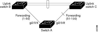
In Figure 2-1, ports 1 and 2 on switch A are connected to uplink switches B and C. Because they are configured as Flex Links, only one of the interfaces is forwarding traffic; the other is in standby mode. If port 1 is the active link, it begins forwarding traffic between port 1 and switch B; the link between port 2 (the backup link) and switch C is not forwarding traffic. If port 1 goes down, port 2 comes up and starts forwarding traffic to switch C. When port 1 comes back up, it goes into standby mode and does not forward traffic; port 2 continues forwarding traffic.
Preemption
You can also choose to configure a preemption mechanism, specifying the preferred port for forwarding traffic. In Figure 2-1, for example, you can configure the Flex Link pair with preemption mode so that after port 1 comes back up in the scenario, if it has greater bandwidth than port 2, port 1 begins forwarding after 60 seconds; and port 2 becomes the standby. You do this by entering the interface configuration switchport backup interface preemption mode bandwidth and switchport backup interface preemption delay commands.
Figure 2-1 Flex Links Configuration Example

If a primary (forwarding) link goes down, a trap notifies the network management stations. If the standby link goes down, a trap notifies the users.
Flex Links are supported only on Layer 2 ports and port channels, not on VLANs or Layer 3 ports.
VLAN Flex Link Load Balancing and Support
VLAN Flex Link load-balancing allows users to configure a Flex Link pair so that both ports simultaneously forward the traffic for some mutually exclusive VLANs. For example, if Flex Link ports are configured for 1-100 VLANs, the traffic of the first 50 VLANs can be forwarded on one port and the rest on the other port. If one of the ports fail, the other active port forwards all the traffic. When the failed port comes back up, it resumes forwarding traffic in the preferred vlans. This way, apart from providing the redundancy, this Flex Link pair can be used for load balancing. Also, Flex Link VLAN load-balancing does not impose any restrictions on uplink switches.
Figure 2-2 VLAN Flex Links Load Balancing Configuration Example
Flex Link Multicast Fast Convergence
Flex Link Multicast Fast Convergence reduces the multicast traffic convergence time after a Flex Link failure. This is implemented by a combination of these solutions:
Learning the Other Flex Link Port as the mrouter Port
In a typical multicast network, there is a querier for each VLAN. A switch deployed at the edge of a network has one of its Flex Link ports receiving queries. Flex Link ports are also always forwarding at any given time.
A port that receives queries is added as an mrouter port on the switch. An mrouter port is part of all the multicast groups learned by the switch. After a changeover, queries are received by the other Flex Link port. The other Flex Link port is then learned as the mrouter port. After changeover, multicast traffic then flows through the other Flex Link port. To achieve faster convergence of traffic, both Flex Link ports are learned as mrouter ports whenever either Flex Link port is learned as the mrouter port. Both Flex Link ports are always part of multicast groups.
Though both Flex Link ports are part of the groups in normal operation mode, all traffic on the backup port is blocked. So the normal multicast data flow is not affected by the addition of the backup port as an mrouter port. When the changeover happens, the backup port is unblocked, allowing the traffic to flow. In this case, the upstream multicast data flows as soon as the backup port is unblocked.
Generating IGMP Reports
When the backup link comes up after the changeover, the upstream new distribution switch does not start forwarding multicast data, because the port on the upstream router, which is connected to the blocked Flex Link port, is not part of any multicast group. The reports for the multicast groups were not forwarded by the downstream switch because the backup link is blocked. The data does not flow on this port, until it learns the multicast groups, which occurs only after it receives reports.
The reports are sent by hosts when a general query is received, and a general query is sent within 60 seconds in normal scenarios. When the backup link starts forwarding, to achieve faster convergence of multicast data, the downstream switch immediately sends proxy reports for all the learned groups on this port without waiting for a general query.
Leaking IGMP Reports
To achieve multicast traffic convergence with minimal loss, a redundant data path must be set up before the Flex Link active link goes down. This can be achieved by leaking only IGMP report packets on the Flex Link backup link. These leaked IGMP report messages are processed by upstream distribution routers, so multicast data traffic gets forwarded to the backup interface. Because all incoming traffic on the backup interface is dropped at the ingress of the access switch, no duplicate multicast traffic is received by the host. When the Flex Link active link fails, the access switch starts accepting traffic from the backup link immediately. The only disadvantage of this scheme is that it consumes bandwidth on the link between the distribution switches and on the backup link between the distribution and access switches. This feature is disabled by default and can be configured by using the switchport backup interface interface-id multicast fast-convergence command.
When this feature has been enabled at changeover, the switch does not generate the proxy reports on the backup port, which became the forwarding port.
Configuration Examples
This configuration example shows learning the other Flex Link port as the mrouter port when Flex Link is configured on Gigabit Ethernet interface 0/11 and Gigabit Ethernet interface 0/12. The example shows the output for the show interfaces switchport backup command:
This output shows a querier for VLANs 1 and 401, with their queries reaching the switch through Gigabit Ethernet interface 0/11:
This is output for the show ip igmp snooping mrouter command for VLANs 1 and 401:
Similarly, both Flex Link ports are part of learned groups. In this example, Gigabit Ethernet interface 0/10 is a receiver/host in VLAN 1, which is interested in two multicast groups:
When a host responds to the general query, the switch forwards this report on all the mrouter ports. In this example, when a host sends a report for the group 228.1.5.1, it is forwarded only on Gigabit Ethernet interface 0/11, because the backup port Gigabit Ethernet 0/12 interface is blocked. When the active link, Gigabit Ethernet interface 0/11, goes down, the backup port, Gigabit Ethernet interface 0/12, begins forwarding.
As soon as this port starts forwarding, the switch sends proxy reports for the groups 228.1.5.1 and 228.1.5.2 on behalf of the host. The upstream router learns the groups and starts forwarding multicast data. This is the default behavior of Flex Link. This behavior changes when the user configures fast convergence using the switchport backup interface gigabitethernet 0/12 multicast fast-convergence command. This example shows turning on this feature:
This output shows a querier for VLAN 1 and 401 with their queries reaching the switch through Gigabit Ethernet interface 0/11:
This is output for the show ip igmp snooping mrouter command for VLAN 1 and 401:
Similarly, both the Flex Link ports are a part of the learned groups. In this example, Gigabit Ethernet interface 0/10 is a receiver/host in VLAN 1, which is interested in two multicast groups:
When a host responds to the general query, the switch forwards this report on all the mrouter ports. When you turn on this feature through the command-line port, and when a report is forwarded by the switch on Gigabit Ethernet interface 0/11, it is also leaked to the backup port Gigabit Ethernet interface 0/12. The upstream router learns the groups and starts forwarding multicast data, which is dropped at the ingress because Gigabit Ethernet interface 0/12 is blocked. When the active link, Gigabit Ethernet interface 0/11, goes down, the backup port, Gigabit Ethernet interface 0/12, begins forwarding. You do not need to send any proxy reports as the multicast data is already being forwarded by the upstream router. By leaking reports to the backup port, a redundant multicast path has been set up, and the time taken for the multicast traffic convergence is very minimal.
MAC Address-Table Move Update
The MAC address-table move update feature allows the switch to provide rapid bidirectional convergence when a primary (forwarding) link goes down and the standby link begins forwarding traffic.
In Figure 2-3, switch A is an access switch, and ports 1 and 2 on switch A are connected to uplink switches B and D through a Flex Link pair. Port 1 is forwarding traffic, and port 2 is in the backup state. Traffic from the PC to the server is forwarded from port 1 to port 3. The MAC address of the PC has been learned on port 3 of switch C. Traffic from the server to the PC is forwarded from port 3 to port 1.
If the MAC address-table move update feature is not configured and port 1 goes down, port 2 starts forwarding traffic. However, for a short time, switch C keeps forwarding traffic from the server to the PC through port 3, and the PC does not get the traffic because port 1 is down. If switch C removes the MAC address of the PC on port 3 and relearns it on port 4, traffic can then be forwarded from the server to the PC through port 2.
If the MAC address-table move update feature is configured and enabled on the switches in Figure 2-3 and port 1 goes down, port 2 starts forwarding traffic from the PC to the server. The switch sends a MAC address-table move update packet from port 2. Switch C gets this packet on port 4 and immediately learns the MAC address of the PC on port 4, which reduces the reconvergence time.
You can configure the access switch, switch A, to send MAC address-table move update messages. You can also configure the uplink switches B, C, and D to get and process the MAC address-table move update messages. When switch C gets a MAC address-table move update message from switch A, switch C learns the MAC address of the PC on port 4. Switch C updates the MAC address table, including the forwarding table entry for the PC.
Switch A does not need to wait for the MAC address-table update. The switch detects a failure on port 1 and immediately starts forwarding server traffic from port 2, the new forwarding port. This change occurs in 100 milliseconds (ms). The PC is directly connected to switch A, and the connection status does not change. Switch A does not need to update the PC entry in the MAC address table.
Figure 2-3 MAC Address-Table Move Update Example

Guidelines and Limitations
- You can configure up to 16 backup Flex Links.
- You can configure only one Flex Link backup link for any active link, and it must be on a different interface than the active interface.
- An interface can belong to only one Flex Link pair.
- An interface can be a backup link for only one active link. An active link cannot belong to another Flex Link pair.
- Neither of the links (active or backup) can be a port that belongs to an EtherChannel.
However, you can configure two port channels (EtherChannel logical interfaces) as Flex Links, and you can configure a port channel and a physical interface as Flex Links, with either the port channel or the physical interface as the active link.
- A backup link does not have to be the same type (Fast Ethernet, Gigabit Ethernet, or port channel) as the active link. However, we recommend that you configure both Flex Links with similar characteristics so that there are no loops or changes in behavior if the standby link begins to forward traffic.
- STP is disabled on Flex Link ports. When STP is configured on the switch, Flex Links do not participate in STP within any VLANs. Ensure that there are no loops in the configured topology, when not operating with STP.
Note STP is available only on NNIs or ENIs.
Default Settings
|
|
|
|---|---|
Configuring Flex Links and MAC Address Table Move Update
- Enabling the Flex Link
- Defining a Flex Link Preemption Scheme
- Configuring VLAN Load Balancing on Flex Links
- Configuring MAC Address-Table Move Update
Enabling the Flex Link
BEFORE YOU BEGIN
Review the Guidelines and Limitations for this feature. (See Guidelines and Limitations.)
DETAILED STEPS
EXAMPLE
This example shows how to configure an interface with a backup interface:
Defining a Flex Link Preemption Scheme
Configure a preemption scheme for the Flex Links pair (active and backup links).
BEFORE YOU BEGIN
Review the Guidelines and Limitations for this feature. (See Guidelines and Limitations.)
Define and enable the Flex Link. (See Enabling the Flex Link.)
Determine what preemption mode, if any, you want to assign to the port. (See Preemption.)
DETAILED STEPS
EXAMPLE
This example shows how to configure the preemption mode as forced for a backup interface pair:
Configuring VLAN Load Balancing on Flex Links
BEFORE YOU BEGIN
Review the Guidelines and Limitations for this feature. (See Guidelines and Limitations.)
Define and enable the Flex Link. (See Enabling the Flex Link.)
DETAILED STEPS
EXAMPLE
In the following example, VLANs 1 to 50, 60, and 100 to 120 are configured on the switch:
When both interfaces are up, Gigabit Ethernet port 0/8 forwards traffic for VLANs 60 and 100 to 120 and Gigabit Ethernet port 0/6 forwards traffic for VLANs 1 to 50.
When a Flex Link interface goes down (LINK_DOWN), VLANs preferred on this interface are moved to the peer interface of the Flex Link pair. In this example, if interface Gigabit Ethernet port 0/6 goes down, Gigabit Ethernet port 0/8 carries all VLANs of the Flex Link pair.
When a Flex Link interface comes up, VLANs preferred on this interface are blocked on the peer interface and moved to the forwarding state on the interface that has just come up. In this example, if interface 0/6 comes up, VLANs preferred on this interface are blocked on the peer interface 0/8 and forwarded on 0/6.
Configuring MAC Address-Table Move Update
Configuring a switch to send and get MAC address-table move updates.
Sending MAC Address Table Move Updates
BEFORE YOU BEGIN
Review the Guidelines and Limitations for this feature. (See Guidelines and Limitations.)
DETAILED STEPS
EXAMPLE
This example shows how to configure an access switch to send MAC address-table move update messages:
Getting MAC Address Table Move Updates
BEFORE YOU BEGIN
Review the Guidelines and Limitations for this feature. (See Guidelines and Limitations.)
DETAILED STEPS
EXAMPLE
This example shows how to configure a switch to get and process MAC address-table move update messages:
Verifying Configuration
EXAMPLE
This example shows detailed configuration information for the Flex Link pair.
Active Interface Backup Interface State
------------------------------------------------------------------------
GigabitEthernet0/21 GigabitEthernet0/2 Active Up/Backup Standby
Feature History
|
|
|
|---|---|
 Feedback