Migrating Existing Networks to Cisco ACI
Available Languages
Migrating Existing Networks to
Cisco ACI
Contents
Migrating a Brownfield Network to Cisco ACI
Layer 2 Connectivity with VLAN to EPG Static Mapping
Virtual Workloads Migration Considerations
Default Gateway Migration Considerations
Layer 3 Routing Between Brownfield and Greenfield Networks
Migration of Layer 4 to Layer 7 Network Services
Introduction
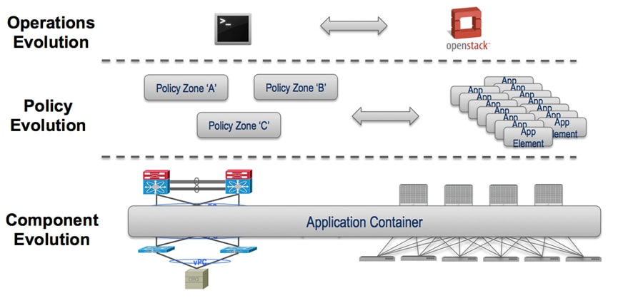
There are several current and future trends happening concurrently in the data center space, described as follows:
■ Operations evolution: Moving from the use of the CLI to orchestration tools to manage and operate the data center network.
■ Policy evolution: Evolving from standard IP subnet firewall-based access control to advanced, policy-based access control, which allows deploying new applications into a Cisco ACI greenfield environment in a more “application-centric” manner.
■ Component evolution: Interconnecting existing data center network infrastructure to newly deployed Cisco ACI fabrics to allow applications to be gradually migrated from one infrastructure to another, ideally in a non-disruptive manner.
These three evolution paths (shown as follows) may occur in parallel or in an independent and sequential way. The main purpose of this guide is the migration of the underlying infrastructure.
Note: A solid understanding of Cisco ACI and its functionalities is required to leverage the information contained in this guide. For more background information on Cisco ACI, refer to the following link: http://www.cisco.com/go/aci.
Migrating a Brownfield Network to Cisco ACI
The specific migration process described in this guide is usually referred to as “network centric migration” and consists in interconnecting the existing brownfield network (built based on STP, vPC, or FabricPath technologies) to a newly developed Cisco ACI POD with the end goal of migrating applications or workloads between those environments.
In order to accomplish this application migration task, it is required to map traditional networking concepts (VLANs, IP subnets, VRFs, etc.) to new Cisco ACI constructs, like endpoint groups (EPGs), bridge domains, and Private Networks. The Cisco ACI constructs previously mentioned is explained in more detail throughout this guide.
The following diagram shows the Cisco ACI network-centric migration methodology, which highlights the major steps required for performing the migration of applications from a brownfield network to a Cisco ACI fabric.
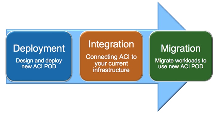
The steps of the Cisco ACI network-centric migration methodology are described as follows:
1. The first step is the design and deployment of the new Cisco ACI POD (greenfield POD); it is likely that the size of such a deployment is initially small with plans to grown in time with the number of applications that are migrated. A typical Cisco ACI POD consists of at least two spine nodes and two leaf nodes, managed by a cluster of Cisco APICs.
2. The second step is the integration between the existing data center network infrastructure (usually called the “brownfield” network) and the new Cisco ACI POD. Layer 2 and Layer 3 connectivity between the two networks is required to allow successful applications and workload migration across the two network infrastructures.
3. The final step consists of migrating workloads between the brownfield and the greenfield network. This application migration process may take several months to complete (depending also on the number and complexity of the applications being migrated), so communication between greenfield and brownfield networks through the Layer 2 and Layer 3 connections previously mentioned is utilized during this phase.
Layer 2 Connectivity with VLAN to EPG Static Mapping
In Cisco ACI, VLANs do not exist inside the fabric; they are only defined on the edge ports connecting virtual or physical endpoints. Hence, the meaning of the VLAN tags is localized on a per interface level. This method allows the possibility to establish intra-IP subnet communication between devices that are part of Layer 2 segments identified by different VLAN ID tags (VLAN cross-connect) or even other type of tags (VXLAN and NVGRE, for example).
The following diagram shows the Cisco ACI normalization of ingress encapsulation, which demonstrates the fabric normalization of port encapsulations.
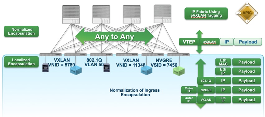
The traditional concept of VLAN as Layer 2 broadcast domain is replaced in the Cisco ACI fabric with a bridge domain, representing the Layer 2 broadcast domain where endpoints (physical or virtual) connect.
As shown in the following diagram, on the Cisco ACI fabric it is possible to associate different VLAN tags (VLAN 20 and 30 in this example) defined on different edge ports to the same broadcast domain. The result is that endpoint 10.10.10.10 can still communicate with endpoint 10.10.10.11 even though they are attached to different VLANs.
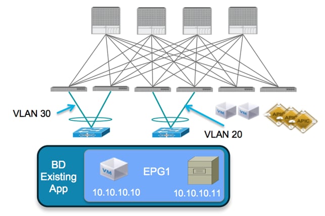
It is then possible to deploy endpoints as part of a specific security group, called an endpoint group (EPG) that is associated with the bridge domain. In traditional networking, different security groups are usually associated to separate VLANs (Layer 2 broadcast domains) and security policies get applied by leveraging Layer 3 ACLs defined on the routing devices interconnecting them.
The recommended approach for a network centric migration consists of associating each VLAN originally defined in the brownfield infrastructure to a corresponding EPG and bridge domain pair in the Cisco ACI fabric (VLAN = EPG = BD). It should be noted that while the above is our recommended approach, Cisco ACI does give you the ability to associate more than one endpoint group to the same Layer 2 broadcast domain, while maintaining logical isolation between endpoints in the respective EPGs.
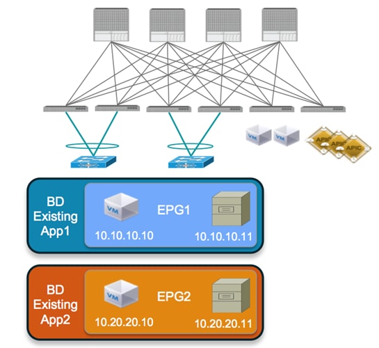
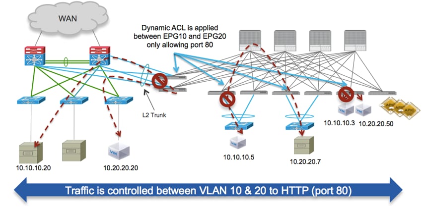
The following diagram shows the mapping of each migrated application to a separate EPG/bridge domain. Endpoints 10.10.10.10 and 10.10.10.11 cannot communicate to endpoints 10.20.20.10 or 10.20.20.11 unless explicitly configured. This holds true even if all the hosts were on the same Layer 2 domain or IP subnet.
To connect the brownfield network and the Cisco ACI fabric using Layer 2 and perform the workload migration:
1. Establish a double-sided vPC connection between a pair of Cisco ACI border leaf nodes and the two devices
representing the boundary between Layer 2 and Layer 3 in the brownfield infrastructure. Depending on the technology used in the legacy network (STP, vPC, or FabricPath), this Layer 2/Layer 3 boundary may be found at the aggregation layer or on a dedicated pair of devices normally named border leaf nodes. The following diagram shows brownfield VLANs connected to the Cisco ACI fabric.
Note: The use of a dedicated border leaf node pair is recommended but not required.
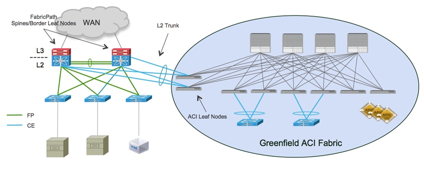
In the previous example, the brownfield network is represented by a FabricPath implementation leveraging a default gateway deployment at the spine layer (that is, the spines also perform the duty of border leaf nodes). A double-sided vPC+ connection to a pair of Cisco ACI leaf nodes allows extending Layer 2 connectivity between the two network infrastructures without creating any Layer 2 loop, hence maintaining all the vPC links actively forwarding traffic.
Note: This design would look identical if the brownfield network was built with STP or vPC technologies as opposed to FabricPath.
2. Associate endpoints connected to VLANs in the brownfield network to security groups defined in the Cisco ACI fabric and named endpoint groups (EPGs). The recommended approach discussed in this paper consists in statically mapping VLAN tags to EPGs on the Cisco ACI leaf nodes connecting to the brownfield network. When doing so, there are a couple of specific use cases worth considering.
Scenario 1: 1:1 Mapping between Brownfield VLANs and EPGs
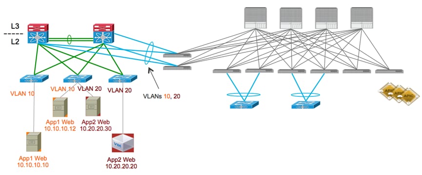
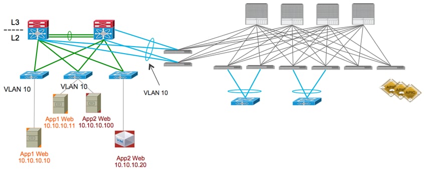
The first case involves an application that is being migrated from a classical multi-tier architecture, where each tier is associated to a separate VLAN segment. Each VLAN segment, in this case, is dedicated to a given application tier, and a different application would use a different VLAN for the same tier (that is, workloads for the Web Tier of App1 are deployed on VLAN 10, and workloads for the Web Tier of App2 on VLAN 20, as shown in the following diagram:
In this scenario, which is shown in the following diagram, performing VLAN10/EPG1 and VLAN20/EPG2 static mappings ensures that the workloads connected to the brownfield network remain part of the same Layer 2 broadcast domain with the workloads that are migrated to the Cisco ACI fabric.
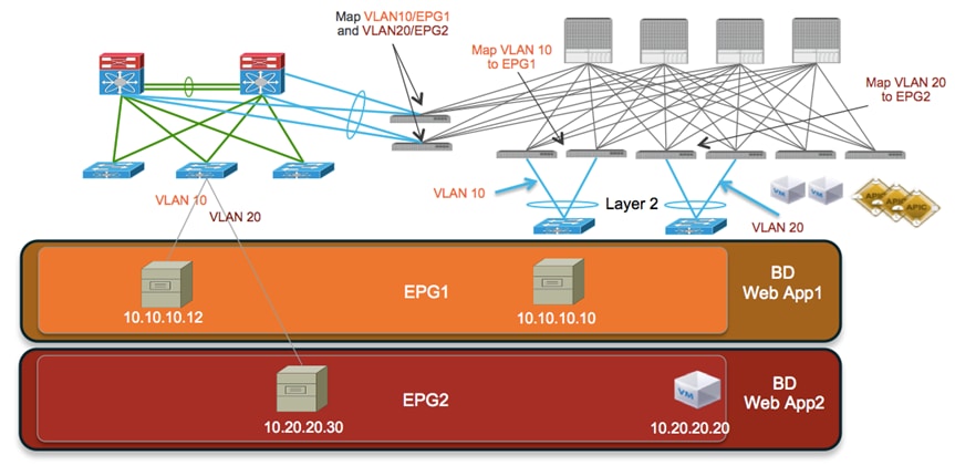
Also, as previously explained, different VLAN tags can be used for the workloads migrated to the Cisco ACI fabric, as long as they are also mapped to the proper EPG1 or EPG2 group, as shown above.
The examples shown in the previous diagrams follow the recommended approach of assigning a dedicated bridge domain and EPG for each brownfield VLAN (brownfield VLAN = EPG = BD). Once the static mapping is performed, Layer 2 (intra-IP subnet) communication can be successfully established between workloads connected to the brownfield FabricPath and the greenfield (Cisco ACI fabric) networks.
Using the VLAN to EPG static binding method allows you to migrate workloads to the Cisco ACI fabric in the least disruptive way. If the workloads are virtualized, it is possible to perform VM live migration (more considerations about this can be found in the “Virtual Workloads Migration Considerations” section). If the workloads are bare-metal servers, it is possible to physically move it between networks without having to perform any IP re-addressing.
Scenario 2: Mapping a Brownfield VLAN to Different EPGs
The second scenario is where the applications in the brownfield network are still deployed with multiple tiers, but the same VLAN segment is utilized by workloads belonging to the same tier of different applications (that is, workloads for the Web Tier of App1 and App2 are all connected to the same VLAN 10, as depicted in the following diagram).
The goal is to have workloads migrated to the Cisco ACI fabric and eventually assigned to separate EPGs, to take advantage of the security functionalities offered by Cisco ACI to logically isolate groups of endpoints. The static VLAN/EPG mapping performed on the Cisco ACI leaf nodes causes the assignment of the workloads part of VLAN 10 to a common EPG, as shown in the following diagram:
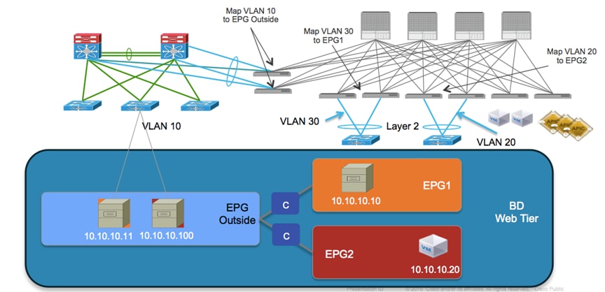
In this scenario, the workloads belonging to the Web tier of different applications are logically isolated between them as soon as they are migrated to the Cisco ACI fabric. To allow communication to the workloads located in the brownfield network, a contract is required between EPG_Outside and EPG1 and between EPG_Outside and EPG2. A contract is a Cisco ACI construct that allows or denies communication between EPGs.
Virtual Workloads Migration Considerations
Specific considerations are required for the migration of virtual workloads between the brownfield network and the Cisco ACI fabric. The focus of this guide is on vSphere deployments, as ESXi is likely the prevalent hypervisor utilized in brownfield deployments. The main goal of the migration procedure is to ensure that virtual machines originally connected to the brownfield network can be moved to ESXi resources in the newly deployed Cisco ACI fabric. Ideally the procedure should be performed in a seamless manner (that is, live vMotion).
The following two scenarios are probably the most commonly encountered in a real life deployment:
1. Scenario 1: The same vCenter server deployed in the brownfield network to manage locally connected ESXi clusters is also managing new ESXi clusters added to the Cisco ACI fabric.
2. Scenario 2: One (or more) vCenter servers are deployed in the Cisco ACI fabric to manage new ESXi clusters, whereas a separate vCenter server remains connected to the brownfield network to manage locally connected ESXi hosts.
The following two sections describe the migration steps required for these two scenarios.
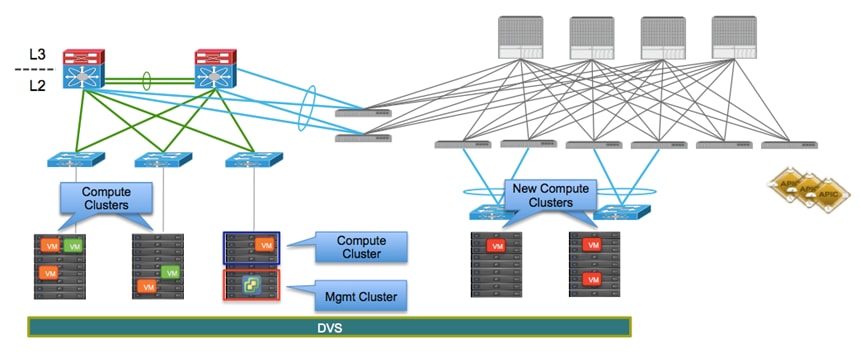
Scenario 1: Single vCenter Server Managing ESXi Clusters in Brownfield and Greenfield
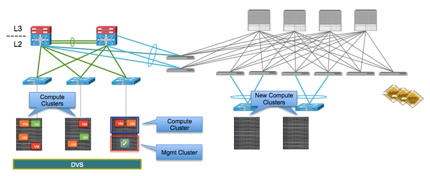
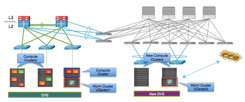
In this scenario, the virtual machines are initially connected to port-groups that have been manually created on the VMware Distributed Virtual Switch (DVS) deployed across the ESXi clusters connected to the brownfield site, as shown in the following diagram:
The following are the steps required to complete the migration procedure:
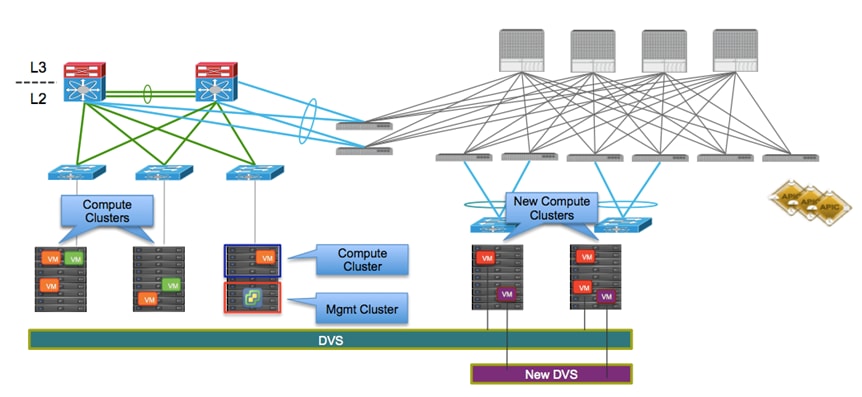
1. Connect the new ESXi hosts in the Cisco ACI fabric to the same DVS already used by the hosts on the brownfield site. This ensures that the port-groups where the virtual machines are initially connected are made available also on the ESXi hosts connected to the Cisco ACI fabric. 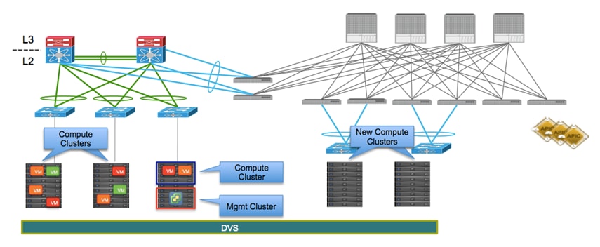
2. At this point, having connected the two networks using Layer 2 as discussed in the previous section, the virtual machines can be migrated in a live fashion (live vMotion) from the brownfield to the greenfield network. In the example in the following diagram, the red VMs are moved to the ESXi hosts connected to the Cisco ACI fabric.
Note: This scenario does not involve VMM integration. You attach to the ESXi hosts and the brownfield environment using a static binding under the EPG (just as you would with bare-metal hosts).
The following diagram shows a live migration of VMs to the Cisco ACI fabric.
The VMs moved to the new ESXi hosts are part of the same port-group used in the brownfield site. This implies that the same VLAN tag is used at this point by the VMs to send traffic into the Cisco ACI fabric. A static mapping is therefore required on the Cisco ACI leaf nodes connecting to the ESXi hosts, so that traffic originated from the migrated VMs can be properly classified and associated to the EPG dedicated to the “red” VMs. Note that this means that the ESXi hosts are in this phase integrated into Cisco ACI as physical resources (that is, part of a physical domain). The default gateway of the newly migrated VMs remains on the brownfield side.
Note: The requirement for the new ESXi host is to be equipped with at least a pair of physical uplinks to be able to be connected simultaneously to the two DVSs.
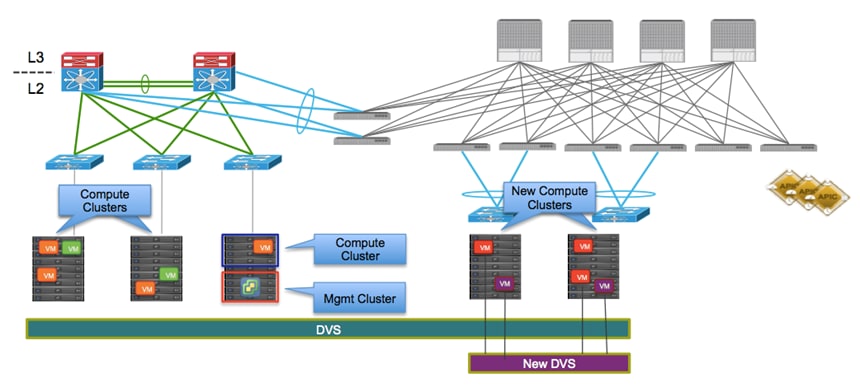
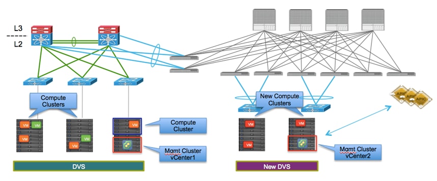
As shown above, the red VMs at this point are still connected to the manually created static port-groups associated to the old DVS, whereas the purple VMs for new applications directly deployed on the Cisco ACI fabric can be connected to dynamically created port-groups associated to the new DVS.
As a last migration step, it is then possible to move the red VMs to the dynamically created port-group associated to the EPG on the new DVS (shown as follows).
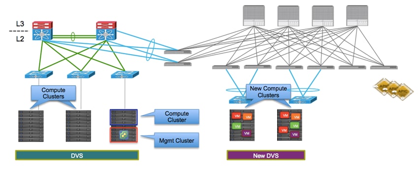
This is advantageous from an operational perspective, because it allows the removal of the old DVS from the configuration at the end of the migration process for all the workloads, as seen in the following diagram. It may also allow for a convenient rollback situation during the migration if any misconfiguration were uncovered in any part of the infrastructure.
Scenario 2: Separate vCenter Servers for Brownfield and Greenfield
In the second scenario, a separate vCenter server is introduced to manage the new ESXi resources connected to the Cisco ACI fabric, as shown in the following diagram.
The migration procedure in this case must be modified as follows:
1. Pair the new vCenter with the Cisco APIC cluster. This process creates a VMM domain and dynamically pushes a new DVS to all the new ESXi hosts in the Cisco ACI fabric. The ESXi hosts can then be connected to this newly created DVS.
2. The EPGs to be used for the migrated workloads are associated to the VMM domain, which implies corresponding port-groups are also dynamically added to the DVS.
3. Perform the live migration of workloads between ESXi clusters. The following diagram shows the inter-vCenter live migration of VMs.
The capability of performing vMotion between ESXi hosts managed by separate vCenter servers has been introduced in vSphere 6.0 software release. Support for integration between Cisco ACI and vSphere 6.0 is introduced in the Cisco ACI 1.1(2h) release.
Note: Support for vMotion between ESXi hosts managed by different vCenter servers is introduced from Cisco ACI release 1.2.
Default Gateway Migration Considerations
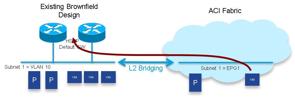
The default gateway used by the workloads to establish communication outside their IP subnet is initially maintained in the brownfield network; this implies that the Cisco ACI fabric initially provides only Layer 2 services for devices part of EPG1, and the workloads already migrated to the Cisco ACI fabric send traffic to the brownfield network when they need to communicate with devices external to their IP subnet (shown in the following diagram).
To enable this behavior, you must configure specific properties on the bridge domain defined in the Cisco ACI fabric and associated to the legacy VLAN 10 (shown in the following diagram). The default settings for a bridge domain have ARP Flooding disabled and Unicast Routing enabled. For Layer 2 communication to work, you must adjust these settings from the defaults.
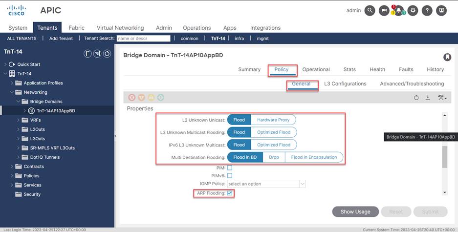
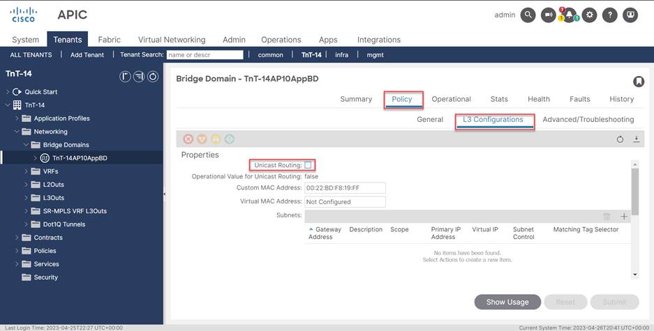
· Disable Unicast Routing: The Cisco ACI fabric must behave as a Layer 2 network in this initial migration phase, therefore it is required to uncheck the flag to disable the Unicast Routing capabilities. As a consequence, the Cisco ACI fabric will only forward traffic for endpoints part of this bridge domain by performing Layer 2 lookups and only MAC address information would be stored in the Cisco ACI database for those workloads (that is, their IP addresses will not be learned).
· Enable ARP flooding: ARP requests originated from devices connected to the Cisco ACI fabric should be able to reach the default gateway or other endpoints part of the same IP subnet and still connected to the brownfield network. Since those entities are unknown to the Cisco ACI fabric, it is required to flood ARP requests across the Cisco ACI fabric and toward the brownfield network.
· Enable Unknown Unicast flooding: similar considerations valid for ARP traffic apply also to Layer 2 unknown traffic (unicast and multicast), so it is required to ensure flooding is enabled in this phase for those traffic types.
Once all (or the majority of) the workloads belonging to the IP subnet are migrated into the Cisco ACI fabric, it is then possible to also migrate the default gateway into the Cisco ACI domain. This migration is done by turning on Cisco ACI routing in the bridge domain and de-configuring the default gateway function on the brownfield network devices.
The following diagram shows how to enable Cisco ACI Unicast Routing.
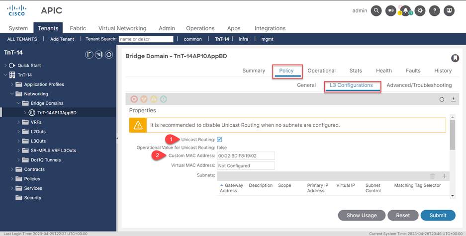
1. Enable unicast routing.
2. Set the gateway MAC address to match the address that you previously used in the brownfield gateway.
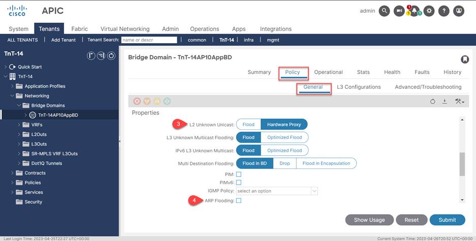
3. Set L2 Unknown Unicast to Hardware Proxy.
4. Disable ARP flooding.
As shown in the previous diagram, Cisco ACI allows the administrator to statically configure the MAC address associated to the default gateway defined for a specific bridge domain: it is therefore possible to use the same MAC address previously used for the default gateway in the legacy network, so that the gateway move is completely seamless for the workloads connected to the Cisco ACI fabric (that is, there is no need to refresh their ARP cache entry).
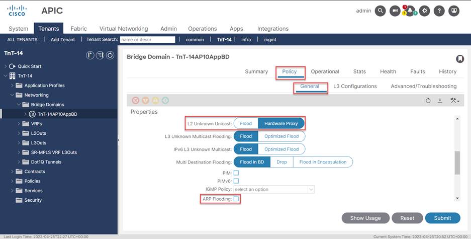
Once the migration of an application is completed, you can leverage all the flooding containment functionalities offered by the Cisco ACI fabric. Specifically, you can set L2 Unknown Unicast to Hardware Proxy and disable ARP flooding.
Note: This is possible only if there are no workloads belonging to that specific Layer 2 broadcast domain that remain connected to the brownfield network (that is, all the workloads, physical and virtual, have been migrated to the Cisco ACI fabric). In real life deployments, there are often specific hosts that remain connected to the brownfield network for quite a long time. This is usually the case for bare-metal servers, like for example Oracle RAC databases that remain untouched until the following refresh cycle. Even in this case it may make sense to move the default gateway for those physical servers to the Cisco ACI fabric. This method will provide the environment with a centralized point of management for security policies, which can be applied between IP subnets; however, the flooding of traffic must remain enabled.
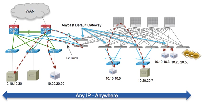
Once the default gateway for different IP subnets is moved to the Cisco ACI fabric, routing communication between workloads belonging to the migrated subnets will always occur on the Cisco ACI leaf nodes leveraging the distributed Anycast gateway functionality.
As shown in the following diagram, this is true for workloads that are still connected to the brownfield network (routing happens on the pair of border leaf nodes interconnecting brownfield and greenfield infrastructure). Once workloads are migrated to the Cisco ACI fabric, traffic will be routed by leveraging the Anycast gateway functionality on the leaf node where they are connected.
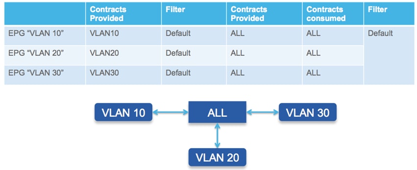
Migrating the workloads and their default gateway to the Cisco ACI fabric brings advantages even when maintaining the security policies at the IP subnet level, as it allows the Cisco ACI fabric to become the single point of security policy enforcement between IP subnets hence providing a sort of ACL management functionality. As always, this can be achieved following a gradual procedure: once the default gateway for the different IP subnets has been moved to the Cisco ACI fabric, it is possible to enable full and open connectivity between endpoints connected to different EPGs (IP subnets), by simply applying a “permit any” contract between the different EPGs (shown as follows).
With this configuration in place, every time a workload tries to communicate with a device in a different EPG (IP subnets), a centrally managed security policy is applied to the Cisco ACI leaf node where the distributed default gateway function is enabled. Given the fact that the policy has a single “permit any” statement, this results in open connectivity between the devices, as shown in the following diagram.
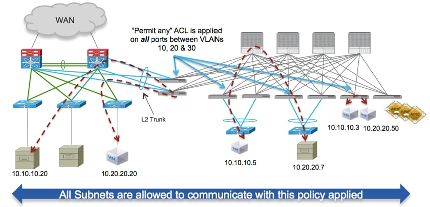
As previously mentioned, because routing between different IP subnets is performed at the Cisco ACI fabric level, the security policy can be enforced not only between hosts connected to the Cisco ACI fabric, but will also be applied to devices connected to VLAN segments in the brownfield infrastructure.
A key advantage of the Cisco ACI centrally managed policy system is the ability to restrict communication between hosts belonging to different IP subnets. With Cisco ACI, it is possible to restrict communication between hosts in a holistic manner by applying a central policy from the Cisco APIC, dictating which traffic flows are allowed and to and from each of the respective EPGs.
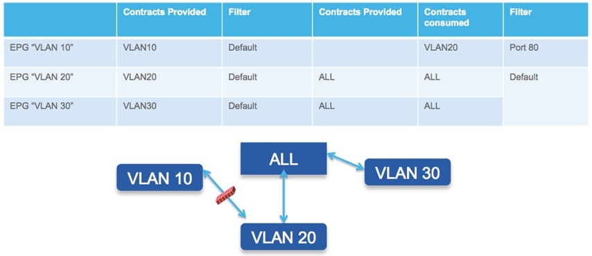
The data plane security policy enforcement between a pair of EPGs is shown in the following diagram.
Layer 3 Routing Between Brownfield and Greenfield Networks
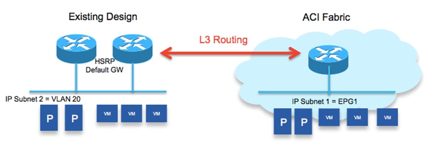
Even though the brownfield and greenfield networks are connected at Layer 2, there may still be IP subnets/VLANs that are not extended to the Cisco ACI fabric. For workloads belonging to the Cisco ACI fabric to communicate with those IP subnets, Layer 3 routing should be enabled between the Cisco ACI fabric and the brownfield network, as shown in the following diagram:
Given that the establishment of dynamic routing peering through a vPC connection is not fully supported across different Cisco Nexus platforms, and that it is likely that the brownfield network is already connected to the WAN using an additional pair of Layer 3 core devices, one possible approach the approach consists in leveraging dedicated Layer 3 links connect the Cisco ACI fabric to those Layer 3 devices, as shown in the following diagram.
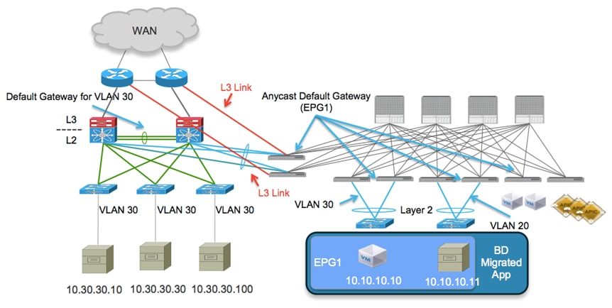
Note: Using a pair of Layer 3 links is usually sufficient, but to increase the resiliency of the solution it is also possible to deploy a full mesh of connections between the Cisco ACI leaf nodes and the Layer 3 devices. Also, an alternative design option could be used to connect the Cisco ACI nodes to the brownfield aggregation/spine nodes. The approach shown above is preferred, as it simplifies the eventual migration to the Cisco ACI fabric of connectivity to the WAN.
In this scenario, the Cisco ACI fabric sees the IP subnet 10.30.30.0/24 as an external prefix reachable using an L3Out connection established with the pair of Layer 3 devices in the brownfield network. Devices connected to the Cisco ACI fabric, and belonging to EPG1, can benefit from the Anycast Default Gateway functionalities.
Migration of Layer 4 to Layer 7 Network Services
Cisco ACI does not offer yet the capability to integrate network service functions (like FW and SLB) between endpoints belonging to separate EPGs based on a dynamic policy configuration, a functionality called “Policy Based Redirection” (PBR). This implies that it is required to deploy more traditional design options to ensure traffic can be sent across a chain of network services. The adopted solution depends on the mode of deployment of the network services:
1. Network services in transparent mode: least common model, after migrating the network services to the Cisco ACI fabric, the fabric performs traffic stitching across the service nodes and offers distributed default gateway and access control services to the workloads deployed in different EPGs.
2. Network services as default gateway for the workloads: when migrating the network services to Cisco ACI, the Cisco ACI simply offers Layer 2 services to allow workload to communicate with the gateway.
3. Network services in routed mode and stitched in the data path (“VRF sandwich”): the Cisco ACI fabric is the default gateway for the tenant workload and the use of VRF stitching is in place to ensure traffic traverses the various network services node.
Independently from the specific network services deployment model, the procedure to integrate those services into the Cisco ACI fabric remains similar and leverages the fact that network services are usually deployed as a pair of active / standby nodes. This is true regardless of whether or not the network service devices are physical or virtual.
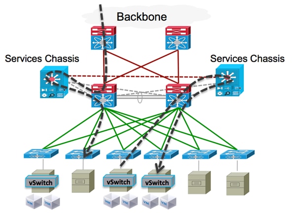
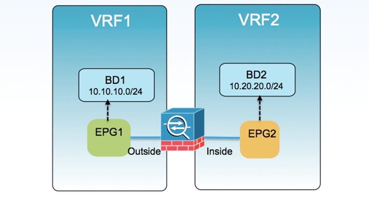
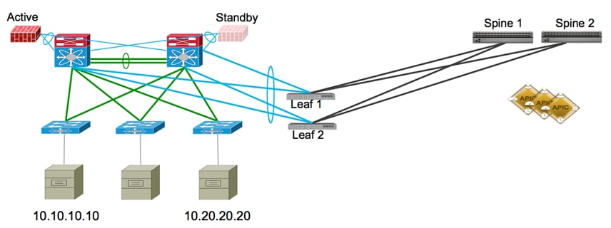
For example, consider the migration procedure required for the scenario where the network services are deployed in routed mode and stitched in the data path by leveraging VRF stitching. Focus on a FW deployment scenario, in which similar considerations apply to Server Load Balancers. In a traditional data center network design, the network services are usually connected to the devices at the Layer 2/Layer 3 demarcation line, either as physical services appliances or as services modules inserted in a service chassis, shown as follows. (This diagram shows network services in a traditional data center design.)
As shown in the previous diagram, both North-South and East-West traffic is pushed to the network services, in our example leveraging a VRF sandwich approach.
As mentioned in previous sections of this guide, the migration to the Cisco ACI fabric consists not only in moving their workloads initially connected to the brownfield network, but also in relocating into the Cisco ACI fabric specific services like routing and security policy enforcement (as previously shown in this guide). The stitching of traffic through the network services can also be enforced at the Cisco ACI fabric level, leveraging the same VRF sandwich design option. The following diagram shows the VRF sandwich for network services integration.
From a physical perspective, it is likely that the initial Cisco ACI deployment could be built with a limited number of Cisco ACI nodes, for then being scaled out in time, as shown in the simplified option as shown in the following diagram.
(This is a simplified diagram for Layer 2 connectivity to Cisco ACI.)
The following diagram shows an alternate view of the topology, showing the connectivity between the brownfield network and the Cisco ACI fabric:
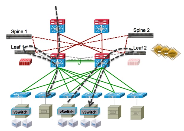
By comparing this diagram with the diagram showing network services in a traditional data center design, you can understand how introducing even a small Cisco ACI fabric built with four nodes allows you to relocate and centralize the routing, access control, and network services functionalities, which will simplify the overall management and operation of the network.
This is the case even when keeping the workloads connected to the brownfield network.
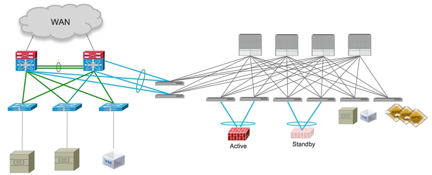
When the goal is the migration of the workloads to the Cisco ACI fabric, the end goal is to relocate not only those workloads but also the services nodes, as shown in the following diagram. (This diagram shows the end state for the migration of network services to the Cisco ACI fabric.)
The procedure for workload migration has already been discussed in the previous sections of this guide. Concerning the migration of network services, it is advantageous that they are usually deployed as a pair of Active/Standby devices. This deployment allows us to provide a seamless migration in two simple steps:
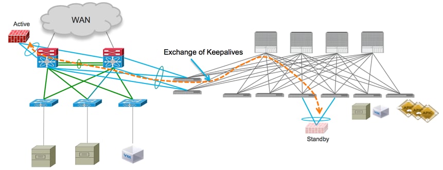
1. Disconnect the standby node from the brownfield network and connect it to a pair of Cisco ACI leaf nodes. A vPC connection is usually leveraged for connecting the network service device to the leaf nodes and a static mapping of local VLAN tags to the proper EPGs ensures proper communication to the network. The keepalives between active and standby nodes can still be exchanged, either using the interconnection links between the brownfield network and the Cisco ACI fabric, or using dedicated OOB connections. As a consequence, the active service node in this phase remains connected to the brownfield network, whereas the standby is connected to the Cisco ACI fabric. The following diagram shows the migration of the standby node to the Cisco ACI fabric.
2. Disconnect the active node from the brownfield network. This triggers the failover event that causes the service node connected to the Cisco ACI fabric to become active. The Cisco ACI fabric is now performing all the routing and VRF stitching functions to ensure all the communications between EPG1 and EPG2 are enforced using the firewall node. The disconnected node is then re-connected to the Cisco ACI fabric; the recommendation is to connect it to the same pair of Cisco ACI leaf nodes where the currently active node is connected, but there is no technical reason not to connect it to a separate pair of leaf nodes.
Cisco and the Cisco logo are trademarks or registered trademarks of Cisco and/or its affiliates in the U.S. and other countries. To view a list of Cisco trademarks, go to this URL: www.cisco.com/go/trademarks. Third-party trademarks mentioned are the property of their respective owners. The use of the word partner does not imply a partnership relationship between Cisco and any other company. (1110R)
Any Internet Protocol (IP) addresses and phone numbers used in this document are not intended to be actual addresses and phone numbers. Any examples, command display output, network topology diagrams, and other figures included in the document are shown for illustrative purposes only. Any use of actual IP addresses or phone numbers in illustrative content is unintentional and coincidental.
© 2023 Cisco Systems, Inc. All rights reserved.
 Feedback
Contact Cisco
- Open a Support Case

- (Requires a Cisco Service Contract)