- Preface
- Overview
- Installing a Cisco Nexus 7004 Switch
- Installing a Cisco Nexus 7009 Chassis
- Installing a Cisco Nexus 7010 Chassis
- Installing a Cisco Nexus 7018 Chassis
- Installing Power Supply Units
- Connecting the Cisco Nexus 7000 Switch to the Network
- Managing system hardware
- Troubleshooting
- Replacement Procedures
- Technical Specifications
- Transceiver and Module Connectors
- Cisco Nexus 7000 Series Accessory Kit Contents
- Chassis and Module LEDs
- Repacking the Nexus 7000 Series Switch for Shipment
- Site Preparation and Maintenance Records
Cisco Nexus 7000 Series Hardware Installation and Reference Guide
Bias-Free Language
The documentation set for this product strives to use bias-free language. For the purposes of this documentation set, bias-free is defined as language that does not imply discrimination based on age, disability, gender, racial identity, ethnic identity, sexual orientation, socioeconomic status, and intersectionality. Exceptions may be present in the documentation due to language that is hardcoded in the user interfaces of the product software, language used based on RFP documentation, or language that is used by a referenced third-party product. Learn more about how Cisco is using Inclusive Language.
- Updated:
- July 8, 2014
Chapter: Installing a Cisco Nexus 7018 Chassis
Installing a Cisco Nexus 7018 Chassis
This chapter describes how to install a new or relocated Cisco Nexus 7018 chassis in a rack or cabinet. For information about installing other Cisco Nexus 7000 Series chassis or power supplies, see the following chapters:
Preparing to Install the Switch
This section includes the following topics:

Note![]() You must have one four-post, 19-inch EIA rack or cabinet before you can install the Cisco Nexus 7018 chassis. Make sure that you order the rack or cabinet and have it delivered before installing the chassis.
You must have one four-post, 19-inch EIA rack or cabinet before you can install the Cisco Nexus 7018 chassis. Make sure that you order the rack or cabinet and have it delivered before installing the chassis.
Required Tools
Before you install the Cisco Nexus 7018 chassis into a rack, make sure that you have the following tools and equipment:
Note![]() Depending on the number of modules installed in the switch, you can minimize the amount of weight that you need to move. To determine the full weight of the switch switch chassis that you are moving, see Table A-6.
Depending on the number of modules installed in the switch, you can minimize the amount of weight that you need to move. To determine the full weight of the switch switch chassis that you are moving, see Table A-6.
Note![]() Although manual torque screwdrivers are recommended, the screwdriver used (whether manual or powered), must be able to be set for the torque settings specified in these instructions.
Although manual torque screwdrivers are recommended, the screwdriver used (whether manual or powered), must be able to be set for the torque settings specified in these instructions.
Note![]() These tools and equipment do not ship with the chassis.
These tools and equipment do not ship with the chassis.
Additional tools and equipment, such as an electrostatic discharge (ESD) wrist strap, that you will also need to install the Cisco Nexus 7018 chassis, are included in the Cisco Nexus 7018 accessory kit.

Note![]() For a list of tools required to assemble and secure the four-post rack or cabinet, see the documentation that the manufacturer shipped with the rack or cabinet.
For a list of tools required to assemble and secure the four-post rack or cabinet, see the documentation that the manufacturer shipped with the rack or cabinet.
Installing a Four-Post Rack or Cabinet
Before you install the switch, you must install a standard four-post, 19-inch EIA data center rack (or in a cabinet that contains such a rack) that meets the requirements listed in the Cisco Nexus 7000 Series Site Preparation Guide. To maximize safety, you should do the following for the rack:

Warning![]() Stability hazard. The rack stabilizing mechanism must be in place, or the rack must be bolted to the floor before you slide the unit out for servicing. Failure to stabilize the rack can cause the rack to tip over. Statement 1048
Stability hazard. The rack stabilizing mechanism must be in place, or the rack must be bolted to the floor before you slide the unit out for servicing. Failure to stabilize the rack can cause the rack to tip over. Statement 1048
- If the rack has bonded construction, connect it to the earth ground to enable you to easily ground the system components that you install and to ground your ESD wrist strap. This step minimizes the chance of electrostatic discharge when you handle ungrounded components before you install them.
Be sure that the rack includes AC power receptacles with the amperage required for the power supply units that you will be installing in the chassis. If you are installing 6-kW power supply units, you must have 20-A circuits. If you are installing 7.5-kW power supply units, you must have 30-A circuits.
Warning![]() Take care when connecting units to the supply circuit so that wiring is not overloaded. Statement 1018
Take care when connecting units to the supply circuit so that wiring is not overloaded. Statement 1018
For instructions on setting up the rack, see the documentation that the manufacturer shipped with the rack.
Unpacking and Inspecting a New Chassis
Before you install a new Cisco Nexus 7018 chassis, you need to unpack and inspect it to be sure that you have all the items that you ordered and verify that the switch was not damaged during shipment. If anything is damaged or missing, contact your customer representative immediately.

Tip![]() Do not discard the shipping container when you unpack the Cisco Nexus 7018 system. Flatten the shipping cartons and store them with the pallet used for the system. If you need to move or ship the system in the future, you will need these containers. For repacking instructions, see Appendix E, “Repacking the Cisco Nexus 7000 Series Switch for Shipment.”
Do not discard the shipping container when you unpack the Cisco Nexus 7018 system. Flatten the shipping cartons and store them with the pallet used for the system. If you need to move or ship the system in the future, you will need these containers. For repacking instructions, see Appendix E, “Repacking the Cisco Nexus 7000 Series Switch for Shipment.”
To inspect the shipment, follow these steps:
Step 1![]() Compare the shipment to the equipment list provided by your customer service representative and verify that you have received all of the ordered items. The shipment should include boxes for the following:
Compare the shipment to the equipment list provided by your customer service representative and verify that you have received all of the ordered items. The shipment should include boxes for the following:
The power supply units are shipped with the chassis but are boxed separately.
To see a list of what is in the accessory kit, see the Cisco Nexus 7018 System Accessory Kit Contents document, which is included in the kit.
Step 2![]() Check the contents of each box or package for damage.
Check the contents of each box or package for damage.
Step 3![]() If you notice any discrepancies or damage, send the following information to your customer service representative by e-mail:
If you notice any discrepancies or damage, send the following information to your customer service representative by e-mail:
- Invoice number of the shipper (see the packing slip)
- Model and serial number of the missing or damaged unit
- Description of the problem and how it affects the installation
Installing the Bottom-Support Rails on the Rack
The bottom-support rails hold the Cisco Nexus 7018 chassis on the rack or cabinet. To maximize the stability of the rack, you must attach these rails at the lowest possible rack unit (RU).
The prerequisites, tools, and process for installing the bottom-support rails are included in the following topics:
- Prerequisites for Attaching the Bottom-Support Rails
- Required Tools and Equipment
- Attaching the Bottom-Support Rails
Prerequisites for Attaching the Bottom-Support Rails
Before you can attach the bottom-support rails, you must fully install the rack or cabinet, and should, for maximum stability, bolt the rack or cabinet to the concrete subfloor. If anything lighter than the Cisco Nexus 7018 system is already installed in the rack, you should make sure that it is positioned above where you will be installing the Cisco Nexus 7000 Series system. Also, you must have the bottom-support rail kit, which ships with the Cisco Nexus 7000 Series accessory kit. The distance between the front and rear mounting brackets on the rack or cabinet must be between 24 and 32 inches (61.0 and 81.3 cm).
Required Tools and Equipment
You need the following tools and equipment to attach the bottom-support rails:
- Number 1 Phillips-head screwdriver with torque capability.
- Rack-mount kit (shipped with the accessory kit). Table 5-1 lists the items in the rack-mount kit.
|
|
|
|---|---|
Attaching the Bottom-Support Rails
To maximize the stability of the rack, you should install the chassis as low as possible on the rack. Install the first system at the bottom of the rack. If you install a second system in the same rack, install it immediately above the lower system if there is enough vertical space. If you are planning to install another system in the rack, make sure that the heaviest system is installed first at the bottom of the rack.
To attach the bottom-support rails to a four-post EIA rack, follow these steps:
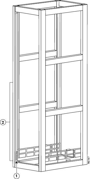
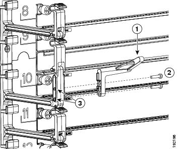
Step 1![]() Position one of the two adjustable bottom-support rails at the lowest possible RU as shown in Figure 5-1. Adjust the length of the rail so that it stretches from the outer edges of the front and rear vertical mounting rails. You can expand the rail so that its mounting brackets are spaced between 24 to 32 inches (61.0 to 81.3 cm).
Position one of the two adjustable bottom-support rails at the lowest possible RU as shown in Figure 5-1. Adjust the length of the rail so that it stretches from the outer edges of the front and rear vertical mounting rails. You can expand the rail so that its mounting brackets are spaced between 24 to 32 inches (61.0 to 81.3 cm).
Note![]() Make sure that the two bottom-support rails are level with one another. If they are not level, adjust the higher rail down to the level of the lower rail.
Make sure that the two bottom-support rails are level with one another. If they are not level, adjust the higher rail down to the level of the lower rail.
Figure 5-1 Positioning the Bottom-Support Rails
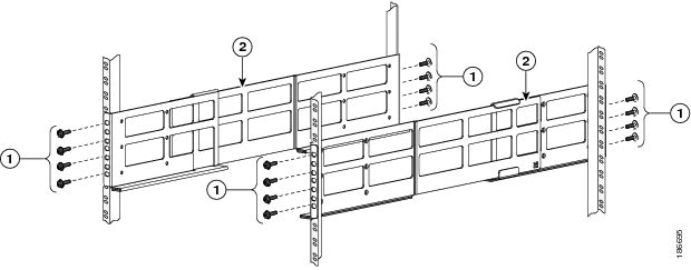
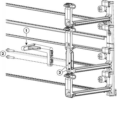
Step 2![]() Use a Phillips torque screwdriver to screw in at least three (four if possible) M6 x 19 mm or 12-24 x 3/4 inch Phillips screws on each end of each rail (using a total of 16 screws for both brackets) as shown in Figure 5-2. Tighten each screw to a maximum of 40 in-lb [4.5 N·m]) of torque.
Use a Phillips torque screwdriver to screw in at least three (four if possible) M6 x 19 mm or 12-24 x 3/4 inch Phillips screws on each end of each rail (using a total of 16 screws for both brackets) as shown in Figure 5-2. Tighten each screw to a maximum of 40 in-lb [4.5 N·m]) of torque.
Note![]() At least three of the screw holes on each end of the bottom-support rail align to the mounting rail. Use at least three screws (four if possible) on each end of each bottom support rail.
At least three of the screw holes on each end of the bottom-support rail align to the mounting rail. Use at least three screws (four if possible) on each end of each bottom support rail.
Figure 5-2 Attaching a Bottom-Support Rail to a Rack
|
|
Four sets of four M6 x 19 mm Phillips screws or four sets of four 12-24 x 3/4 in. Phillips screws (tightened to a maximum of 40 in-lb [4.5 N·m]) |
|
Installing the Chassis
This section describes how to install the chassis (transporting and elevating the chassis to the rack using a mechanical lift, pushing it onto the rack, and then securing it to the rack).
This section includes the following topics:
Prerequisites for Installing the Chassis
Before you install the chassis, you must make sure that the following items are available for the installation:
- Data center ground is accessible where you are installing the Cisco Nexus 7018 chassis.
- Four-post, 19-inch EIA rack or cabinet that includes such a rack.
For more information on the rack or cabinet, see the “Installing a Four-Post Rack or Cabinet” section.
Warning![]() Stability hazard. The rack stabilizing mechanism must be in place, or the rack must be bolted to the floor before you slide the unit out for servicing. Failure to stabilize the rack can cause the rack to tip over. Statement 1048
Stability hazard. The rack stabilizing mechanism must be in place, or the rack must be bolted to the floor before you slide the unit out for servicing. Failure to stabilize the rack can cause the rack to tip over. Statement 1048
- Bottom-support rails installed in the rack or cabinet—You must already have two bottom-support rails attached to the lowest possible rack unit on the chassis.
For more information, see the “Installing the Bottom-Support Rails on the Rack” section.
For more information, see the “Unpacking and Inspecting a New Chassis” section.
Required Tools and Equipment
You need the following tools and equipment to install the Cisco Nexus 7000 Series chassis:
Note![]() Depending on the number of modules installed in the switch, you can minimize the amount of weight that you need to move. You can also remove the fan trays before moving the chassis. To determine the full weight of the switch switch chassis that you are moving, see Table A-6.
Depending on the number of modules installed in the switch, you can minimize the amount of weight that you need to move. You can also remove the fan trays before moving the chassis. To determine the full weight of the switch switch chassis that you are moving, see Table A-6.
Note![]() Although manual torque screwdrivers are recommended, the screwdriver used (whether manual or powered), must be able to be set for the torque settings specified in these instructions.
Although manual torque screwdrivers are recommended, the screwdriver used (whether manual or powered), must be able to be set for the torque settings specified in these instructions.
Part of this kit has already been used to install the bottom-support rails. Table 5-2 lists the items in the rack-mount kit.
|
|
|
|---|---|
Note![]() You should also have at least two persons to push the chassis, which can weigh up to 700 pounds (318 kg) or, if you remove all fan trays and power supplies, it can weigh up to 500 pounds (227 kg), onto and off the mechanical lift and rack. We also recommend that you use a third person for guiding the chassis as it is being pushed.
You should also have at least two persons to push the chassis, which can weigh up to 700 pounds (318 kg) or, if you remove all fan trays and power supplies, it can weigh up to 500 pounds (227 kg), onto and off the mechanical lift and rack. We also recommend that you use a third person for guiding the chassis as it is being pushed.
Installing the Chassis
To install a Cisco Nexus 7018 chassis in a four-post rack or cabinet, follow these steps:
Step 1![]() To lighten the chassis, we recommend that you remove the fan trays from the chassis. The electronics on these modules are well sealed from damage but you must still be careful not to damage their connectors. To remove a fan tray, follow these steps:
To lighten the chassis, we recommend that you remove the fan trays from the chassis. The electronics on these modules are well sealed from damage but you must still be careful not to damage their connectors. To remove a fan tray, follow these steps:
a.![]() Unscrew the four captive screws on the front of the fan tray until they are no longer in contact with the chassis.
Unscrew the four captive screws on the front of the fan tray until they are no longer in contact with the chassis.
b.![]() Grab the fan tray handle and pull the fan tray part way out of the chassis.
Grab the fan tray handle and pull the fan tray part way out of the chassis.
c.![]() Place your other hand under the chassis to support its weight and pull the fan tray fully out of the chassis.
Place your other hand under the chassis to support its weight and pull the fan tray fully out of the chassis.
d.![]() Place the fan tray on an antistatic surface where nothing touches its connectors on the back of the module.
Place the fan tray on an antistatic surface where nothing touches its connectors on the back of the module.
e.![]() If there are power supplies in the chassis, remove the power supplies to minimize the weight of the chassis. The chassis does not ship with power supplies installed, but if you are moving a previously installed chassis, be sure that the power supplies are removed (for instructions on removing power supplies, see the “Removing a 6-kW or 7.5-kW AC Power Supply Unit During Operations” section).
If there are power supplies in the chassis, remove the power supplies to minimize the weight of the chassis. The chassis does not ship with power supplies installed, but if you are moving a previously installed chassis, be sure that the power supplies are removed (for instructions on removing power supplies, see the “Removing a 6-kW or 7.5-kW AC Power Supply Unit During Operations” section).
Step 2![]() Load the chassis onto a mechanical lift as follows:
Load the chassis onto a mechanical lift as follows:
a.![]() Position the mechanical lift next to the shipping pallet that holds the chassis.
Position the mechanical lift next to the shipping pallet that holds the chassis.
b.![]() Elevate the lift platform to the level of the bottom of the chassis (or no more than 1/4 inch [0.6 cm] below the bottom of the chassis).
Elevate the lift platform to the level of the bottom of the chassis (or no more than 1/4 inch [0.6 cm] below the bottom of the chassis).
c.![]() Use at least two persons to slide the chassis fully onto the lift so that the side of the chassis touches or is close to the vertical rails on the lift. Push only the lower half of the frame of the chassis (never push on the modules installed in the chassis and do not use their handles to guide the chassis).
Use at least two persons to slide the chassis fully onto the lift so that the side of the chassis touches or is close to the vertical rails on the lift. Push only the lower half of the frame of the chassis (never push on the modules installed in the chassis and do not use their handles to guide the chassis).
Tip![]() Use a third person to guide the chassis and to make sure that it does not collide with anything or tip over.
Use a third person to guide the chassis and to make sure that it does not collide with anything or tip over.
Warning![]() To prevent personal injury or damage to the chassis, never attempt to lift or tilt the chassis using the handles on modules (such as power supplies, fans, or cards); these types of handles are not designed to support the weight of the unit. Statement 1032
To prevent personal injury or damage to the chassis, never attempt to lift or tilt the chassis using the handles on modules (such as power supplies, fans, or cards); these types of handles are not designed to support the weight of the unit. Statement 1032
Step 3![]() Use the mechanical lift to move and align the rear of the chassis to the front of the four-post rack or cabinet. Make sure that the bottom of the chassis is elevated to the height of the bottom-support rails or no more than 1/4 inch (0.6 cm) above the bracket.
Use the mechanical lift to move and align the rear of the chassis to the front of the four-post rack or cabinet. Make sure that the bottom of the chassis is elevated to the height of the bottom-support rails or no more than 1/4 inch (0.6 cm) above the bracket.
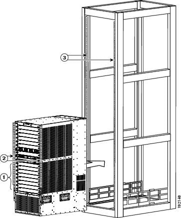
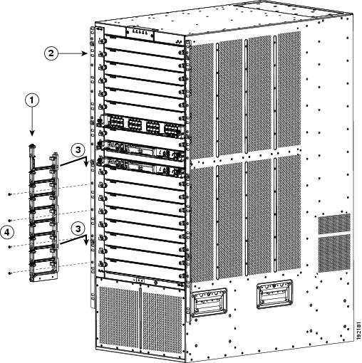
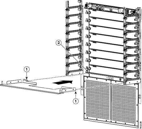
Step 4![]() Use at least two persons to push the chassis half way onto the installed bottom-support rails as shown in Figure 5-3 and a third person to guide the back of the chassis so that it does not get caught on anything as it is pushed into the rack.
Use at least two persons to push the chassis half way onto the installed bottom-support rails as shown in Figure 5-3 and a third person to guide the back of the chassis so that it does not get caught on anything as it is pushed into the rack.
Note![]() Push evenly on both sides of the lower half of the front side of the chassis so that the back side enters the rack first. and push until the chassis is half way onto the rack.
Push evenly on both sides of the lower half of the front side of the chassis so that the back side enters the rack first. and push until the chassis is half way onto the rack.
Tip Use the third person to be sure that the back end of the chassis does not get caught on the expansion edge of the bottom support rails.
Figure 5-3 Moving a Cisco Nexus 7018 Chassis onto a Rack
|
|
Push the sides of the lower half of the front side of the chassis. |
|
|
|
|
|
Step 5![]() Lower the lift until it is no more than 0.25 inches below the bottom support rails. This action ensures that the chassis is not pointing downwards in a way that might get it caught on the expansion edge of the bottom support rails.
Lower the lift until it is no more than 0.25 inches below the bottom support rails. This action ensures that the chassis is not pointing downwards in a way that might get it caught on the expansion edge of the bottom support rails.
Step 6![]() With the chassis flat on the bottom support rails, use two persons to push evenly on each side of the chassis until it is fully loaded onto the rack (the two mounting brackets on the front of the chassis come into contact with the two vertical mounting rails on the front of the rack). Use a third person to guide the chassis so that the rear of the chassis (the side being pushed into the rack) does not get caught on any edges of the bottom support rails.
With the chassis flat on the bottom support rails, use two persons to push evenly on each side of the chassis until it is fully loaded onto the rack (the two mounting brackets on the front of the chassis come into contact with the two vertical mounting rails on the front of the rack). Use a third person to guide the chassis so that the rear of the chassis (the side being pushed into the rack) does not get caught on any edges of the bottom support rails.
Step 7![]() Make sure that the screw holes in the chassis mounting brackets align with the screw holes in the vertical mounting rails.
Make sure that the screw holes in the chassis mounting brackets align with the screw holes in the vertical mounting rails.
If you need to reposition the chassis to align the screw holes, you can use the handles on the sides of the chassis.
Tip![]() To adjust the placement of the chassis so that the screw holes in the chassis mounting brackets align with the screw holes in the vertical mounting rails, use the chassis handles shown in Figure 5-4.
To adjust the placement of the chassis so that the screw holes in the chassis mounting brackets align with the screw holes in the vertical mounting rails, use the chassis handles shown in Figure 5-4.
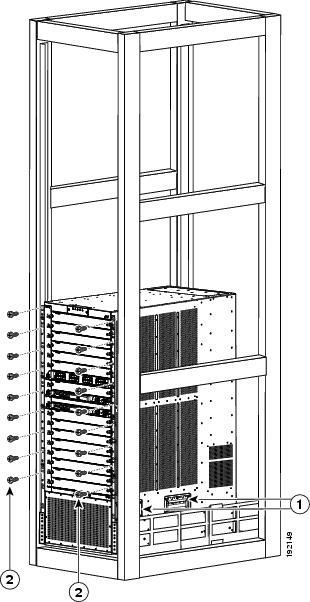
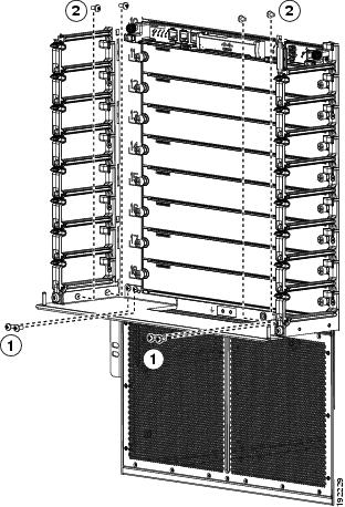
Step 8![]() Use a Phillips torque screwdriver to screw in nine M6 x 19-mm or 12-24 x 3/4-inch screws in each of the two chassis mounting brackets (use a total of 18 screws for two mounting brackets) as shown in Figure 5-4. Tighten each screw to a maximum of 40 in-lb [4.5 N·m] of torque.
Use a Phillips torque screwdriver to screw in nine M6 x 19-mm or 12-24 x 3/4-inch screws in each of the two chassis mounting brackets (use a total of 18 screws for two mounting brackets) as shown in Figure 5-4. Tighten each screw to a maximum of 40 in-lb [4.5 N·m] of torque.
Figure 5-4 Attaching the Cisco Nexus 7018 Chassis to the Rack
|
|
|
Nine M6 x 19 mm or 10-24 x 3/4 in. Phillips screws used to attach each side bracket to a front mounting rail (use a total of 18 screws) |
Grounding the Cisco Nexus 7018 Chassis
The Cisco Nexus 7018 system is grounded through the AC power supply cables and one of two grounding connections on the chassis. The AC power supply cables provide a connection to an earth ground whenever you connect the AC power to the system. The system ground, also referred to as the network equipment building system (NEBS) ground, provides additional grounding for EMI shielding requirements and for the low-voltage supplies (DC-DC converters) on the modules. This grounding system is active even when the AC power cables are not connected to the system. You establish this ground by connecting one of the two grounding pads on the chassis to the rack (if it is connected to an earth ground) or directly to the earth ground for the data center building.
This section includes the following topics:
- Prerequisites for Grounding the Chassis
- Required Tools and Equipment
- Connecting the System Ground
- Connecting Your ESD Wrist Strap to the Chassis
Prerequisites for Grounding the Chassis
Before you can ground the chassis, you must have a connection to the earth ground for the data center building. If you installed the Cisco Nexus 7018 chassis into a bonded rack (see the rack manufacturer’s instructions for more information) that now has a connection to the data center earth ground, you can ground the chassis by connecting its ground ports to the rack. Otherwise, you must connect the chassis grounding ports directly to the data center ground.
Required Tools and Equipment
To connect the system ground, you need the following tools and materials:
- Grounding lug—A two-holed standard barrel lug that supports up to 6 AWG wire. This lug is supplied with the Cisco Nexus 7018 system accessory kit.
- Grounding screws—Two M4 x 8 mm (metric) pan-head screws. These screws are shipped with the Cisco Nexus 7018 system accessory kit.
- Grounding wire—Not supplied with the Cisco Nexus 7018 system accessory kit. This wire should be sized to meet local and national installation requirements. Depending on the power supply and system, a 12 AWG to 6 AWG copper conductor is required for U.S. installations. We recommend that you use commercially available 6 AWG wire. The length of the grounding wire depends on the proximity of the switch to proper grounding facilities.
- Number 1 Phillips-head screwdriver with torque capability.
- Crimping tool to crimp the grounding wire to the grounding lug.
- Wire-stripping tool to remove the insulation from the grounding wire.
Connecting the System Ground
After you have moved the chassis into the rack or cabinet, you are ready to connect the system to the earth ground. After you ground the chassis, you can ground your ESD wrist strap by connecting it to the chassis.
To connect the system ground to the earth ground, follow these steps:
Step 1![]() Use a wire-stripping tool to remove approximately 0.75 inch (19 mm) of the covering from the end of the grounding wire.
Use a wire-stripping tool to remove approximately 0.75 inch (19 mm) of the covering from the end of the grounding wire.
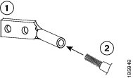
Step 2![]() Insert the stripped end of the grounding wire into the open end of the grounding lug as shown in Figure 5-5.
Insert the stripped end of the grounding wire into the open end of the grounding lug as shown in Figure 5-5.
Figure 5-5 Inserting the Grounding Wire in the Grounding Lug
|
|
|
Grounding cable with 0.75 in. (19 mm) of insulation stripped from the end |
Step 3![]() Use the crimping tool to crimp the lug to the grounding wire. Verify that the ground wire is securely attached to the ground lug by attempting to pull the wire out of the crimped lug.
Use the crimping tool to crimp the lug to the grounding wire. Verify that the ground wire is securely attached to the ground lug by attempting to pull the wire out of the crimped lug.
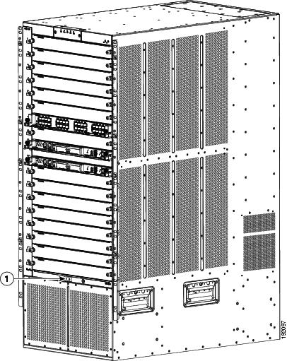
Step 4![]() Remove the adhesive label from one of the two system grounding pads, and secure the grounding wire lug to the grounding pad with two M4 screws. Figure 5-6 shows the location of the grounding pad on the front side of the chassis. Ensure that the grounding lug and the grounding wire do not interfere with other switch hardware or rack equipment.
Remove the adhesive label from one of the two system grounding pads, and secure the grounding wire lug to the grounding pad with two M4 screws. Figure 5-6 shows the location of the grounding pad on the front side of the chassis. Ensure that the grounding lug and the grounding wire do not interfere with other switch hardware or rack equipment.
Figure 5-6 Grounding Pad on the Cisco Nexus 7018 Chassis
|
|
|
Step 5![]() Prepare the other end of the grounding wire and connect it to an appropriate grounding point in your site to ensure an adequate earth ground for the switch. If the rack is grounded, connect the grounding wire as explained in the documentation provided by the vendor for the rack.
Prepare the other end of the grounding wire and connect it to an appropriate grounding point in your site to ensure an adequate earth ground for the switch. If the rack is grounded, connect the grounding wire as explained in the documentation provided by the vendor for the rack.
Connecting Your ESD Wrist Strap to the Chassis
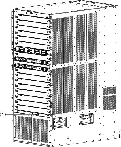
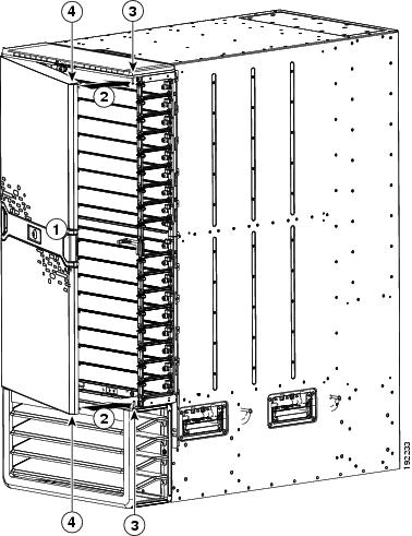
After you connect the chassis to the earth ground, you can ground your ESD wrist strap by plugging it into the ESD port shown in Figure 5-7.
Figure 5-7 ESD Grounding Ports on the Front of the Cisco Nexus 7018 Chassis
|
|
|
Installing the Cable Management Frame
After you have fully installed the Cisco Nexus 7018 switch chassis in the rack or cabinet (see the “Installing the Chassis” section), you can install the cable management frame on the front of the chassis.
When you install the cable management frame, you attach four cable management assemblies to the chassis and then attach a top hood to the top two cable management assemblies and the chassis.
To install the cable management assemblies on the Cisco Nexus 7018 switch chassis, follow these steps:
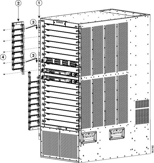
Step 1![]() Attach a lower cable management assembly (800-31343-01) onto the two hooks that protrude from the lower half of the left rack-mount bracket that is attached to the Cisco Nexus 7018 switch chassis, and loosely fasten the assembly to the chassis with four flat-head M4x10 screws as shown in Figure 5-8.
Attach a lower cable management assembly (800-31343-01) onto the two hooks that protrude from the lower half of the left rack-mount bracket that is attached to the Cisco Nexus 7018 switch chassis, and loosely fasten the assembly to the chassis with four flat-head M4x10 screws as shown in Figure 5-8.
Figure 5-8 Attaching a Lower Cable Management Assembly to a Rack-Mount Bracket
Step 2![]() Repeat Step 1 to attach a lower cable management assembly to the right side of the chassis.
Repeat Step 1 to attach a lower cable management assembly to the right side of the chassis.
Step 3![]() Attach an upper cable management assembly (800-31342-01) onto the two hooks that protrude from the upper half of the left rack-mount bracket that is attached to the Cisco Nexus 7018 switch chassis, and loosely fasten the assembly to the chassis with four flat-head M4x10 screws as shown in Figure 5-9.
Attach an upper cable management assembly (800-31342-01) onto the two hooks that protrude from the upper half of the left rack-mount bracket that is attached to the Cisco Nexus 7018 switch chassis, and loosely fasten the assembly to the chassis with four flat-head M4x10 screws as shown in Figure 5-9.
Figure 5-9 Attaching a Left Cable Management Assembly to a Rack-Mount Bracket
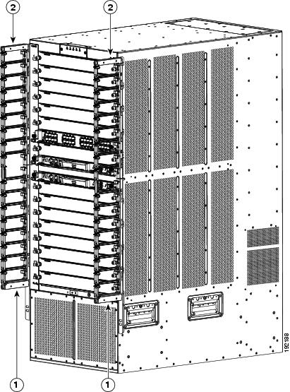
Step 4![]() Repeat Step 3 to attach an upper cable management assembly to the upper right side of the chassis. When completed, the chassis will appear as shown in Figure 5-10.
Repeat Step 3 to attach an upper cable management assembly to the upper right side of the chassis. When completed, the chassis will appear as shown in Figure 5-10.
Figure 5-10 Cable Management Assemblies Attached to the Rack-Mount Brackets
|
|
|
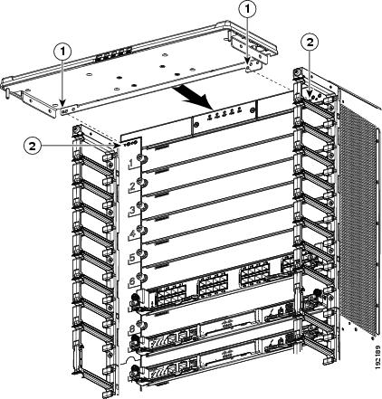
Step 5![]() Place the top hood (800-31269-01) on top of the two upper cable management assemblies that are already installed. Make sure that the side of the top hood that is closest to the chassis has two alignment pins that align with the alignment holes in the chassis as shown in Figure 5-11. Push the top hood toward the chassis so that its alignment pins enter the alignment holes and the top hood rests against the chassis.
Place the top hood (800-31269-01) on top of the two upper cable management assemblies that are already installed. Make sure that the side of the top hood that is closest to the chassis has two alignment pins that align with the alignment holes in the chassis as shown in Figure 5-11. Push the top hood toward the chassis so that its alignment pins enter the alignment holes and the top hood rests against the chassis.
Figure 5-11 Positioning the Top Hood with the Upper Cable Management Assemblies and the Switch Chassis
|
|
|
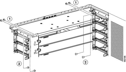
Step 6![]() Use four M4x8 pan-head screws to loosely fasten the top hood to the chassis as shown in Figure 5-12.
Use four M4x8 pan-head screws to loosely fasten the top hood to the chassis as shown in Figure 5-12.
Figure 5-12 Fastening the Top Hood to the Chassis and Cable Management Assemblies
|
|
Four M4x8 pan-head screws that fasten the top hood to the chassis. |
|
Four M4x8 pan-head screws that fasten the top hood to the left and right cable management assemblies. |
Step 7![]() Use four M4x8 pan-head screws to loosely fasten the top hood to each of the two upper cable management assemblies as shown in Figure 5-11.
Use four M4x8 pan-head screws to loosely fasten the top hood to each of the two upper cable management assemblies as shown in Figure 5-11.
Step 8![]() Tighten each of the four screws that fasten the top hood to the chassis to 11 to 15 in-lb (1.2 to 1.7 N·m).
Tighten each of the four screws that fasten the top hood to the chassis to 11 to 15 in-lb (1.2 to 1.7 N·m).
Step 9![]() Tighten each of the four screws that fasten the top hood to the cable management assemblies to 11 to 15 in-lb (1.2 to 1.7 N·m).
Tighten each of the four screws that fasten the top hood to the cable management assemblies to 11 to 15 in-lb (1.2 to 1.7 N·m).
Step 10![]() Tighten each of the 18 screws that fasten the upper and lower cable management assemblies to the rack-mount brackets to 11 to 15 in-lb (1.2 to 1.7 N·m).
Tighten each of the 18 screws that fasten the upper and lower cable management assemblies to the rack-mount brackets to 11 to 15 in-lb (1.2 to 1.7 N·m).
Installing the Front Door and Air Intake Frame
If you need to install the optional double-hinged door and air intake frame, you must install them after installing the cable management frame on the chassis.
Note![]() For the double-hinged door to easily open or close in either direction, make sure that the chassis is level. If necessary, remove the chassis from the rack and adjust the bottom-support rails so that the chassis is level. Also, make sure that the cable management frame is aligned to the vertical sides of the chassis and that the cable management hood is level when you install those components.
For the double-hinged door to easily open or close in either direction, make sure that the chassis is level. If necessary, remove the chassis from the rack and adjust the bottom-support rails so that the chassis is level. Also, make sure that the cable management frame is aligned to the vertical sides of the chassis and that the cable management hood is level when you install those components.
To install the front door and air intake frame to the Cisco Nexus 7018 cable management system, follow these steps:
Step 1![]() Position the left door stopper (700-27454-01) on the middle of the left cable management frame and fasten it with two M3x10 pan-head screws as shown in Figure 5-13. Tighten these two screws to 5 to 7 in-lb (0.6 to 0.8 N·m).
Position the left door stopper (700-27454-01) on the middle of the left cable management frame and fasten it with two M3x10 pan-head screws as shown in Figure 5-13. Tighten these two screws to 5 to 7 in-lb (0.6 to 0.8 N·m).
Figure 5-13 Attaching the Left Door Stopper
|
|
Left door stopper identified with an L on the bottom of the base. |
|
|
|
|
Two M3x10 screws that fasten the stopper to the cable management frame. |
|
Step 2![]() Position the right door stopper (700-27592-01) on the middle of the right side of the cable management frame and fasten it with two M3x10 pan-head screws as shown in Figure 5-14. Tighten these two screws to 5 to 7 in-lb (0.6 to 0.8 N·m).
Position the right door stopper (700-27592-01) on the middle of the right side of the cable management frame and fasten it with two M3x10 pan-head screws as shown in Figure 5-14. Tighten these two screws to 5 to 7 in-lb (0.6 to 0.8 N·m).
Figure 5-14 Attaching the Right Door Stopper
Step 3![]() Position the hinge bracket (700-28491-01) at the bottom of the cable management frame and the chassis as shown in Figure 5-15.
Position the hinge bracket (700-28491-01) at the bottom of the cable management frame and the chassis as shown in Figure 5-15.
Figure 5-15 Positioning the Hinge Bracket to the Cable Management Frame and Chassis
|
|
|
Step 4![]() Attach the bracket to the chassis with eight loosely fastened M4x8 screws, as shown in Figure 5-16.
Attach the bracket to the chassis with eight loosely fastened M4x8 screws, as shown in Figure 5-16.
Figure 5-16 Attaching the Hinge Bracket to the Cable Management Frame and Chassis
|
|
Four M4x8 pan-head screws that fasten the hood to the chassis. |
|
Four M4x8 pan-head screws that fasten the hood to the left and right cable management assemblies. |
Step 5![]() Tighten the four M4x8 screws that fasten the hinge bracket to the chassis to 11 to 15 in-lb (1.2 to 1.7 N·m).
Tighten the four M4x8 screws that fasten the hinge bracket to the chassis to 11 to 15 in-lb (1.2 to 1.7 N·m).
Step 6![]() Tighten the four M4x8 screws that fasten the hinge bracket to the cable management frame to 11 to 15 in-lb (1.2 to 1.7 N·m).
Tighten the four M4x8 screws that fasten the hinge bracket to the cable management frame to 11 to 15 in-lb (1.2 to 1.7 N·m).
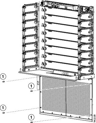
Step 7![]() Fasten the four ball-point studs (51-5008-01), each one with a washer (49-0430-01), to the bottom portion of the chassis, one stud by each corner of the air intake area as shown in Figure 5-17.
Fasten the four ball-point studs (51-5008-01), each one with a washer (49-0430-01), to the bottom portion of the chassis, one stud by each corner of the air intake area as shown in Figure 5-17.
Figure 5-17 Fastening Ball-Point Studs to the Air Intake Area
|
|
|
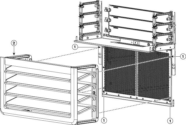
Step 8![]() Align the air intake frame to the four ball-point studs and press the frame onto the chassis as shown in Figure 5-18. The captive screws on the air-intake frame should align with their screw holes in the chassis.
Align the air intake frame to the four ball-point studs and press the frame onto the chassis as shown in Figure 5-18. The captive screws on the air-intake frame should align with their screw holes in the chassis.
Figure 5-18 Positioning the Air Intake Frame on the Chassis
|
|
|
Air-intake frame with holes to be aligned with the ball-headed studs |
Step 9![]() Fasten the captive screws on the air-intake frame to the chassis and tighten to 11 to 15 in-lb (95 to 130 N·m).
Fasten the captive screws on the air-intake frame to the chassis and tighten to 11 to 15 in-lb (95 to 130 N·m).
Step 10![]() On the chassis door, pull the door handle open on one of the two sides of the door until the handle clicks (the handle clicks when you pull it about 30 degrees).
On the chassis door, pull the door handle open on one of the two sides of the door until the handle clicks (the handle clicks when you pull it about 30 degrees).
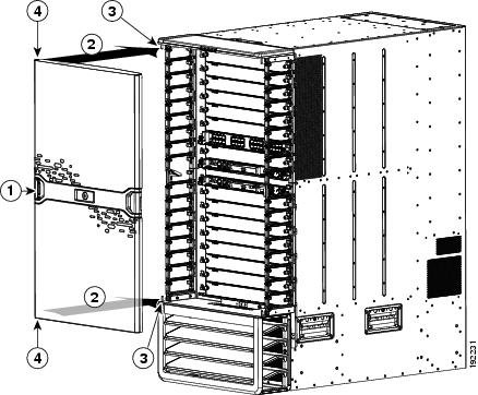
Step 11![]() Move the side of the door with the opened handle onto the two hinge pins as shown in Figure 5-19. Make sure that the top and bottom hinge pins on the hood and hinge bracket fit through the slots on the top and bottom of that side of the door. Position the door so that the hinge pins are located at the ends of the slots.
Move the side of the door with the opened handle onto the two hinge pins as shown in Figure 5-19. Make sure that the top and bottom hinge pins on the hood and hinge bracket fit through the slots on the top and bottom of that side of the door. Position the door so that the hinge pins are located at the ends of the slots.
Note![]() The double-hinge door can be installed and opened on either side. The figures in this procedure show how to install the door on the left side first, but you can use the instructions to install it on either side.
The double-hinge door can be installed and opened on either side. The figures in this procedure show how to install the door on the left side first, but you can use the instructions to install it on either side.
Figure 5-19 Attaching One Side of the Door to the Chassis
|
|
|
||
|
|
|
Step 12![]() While holding the door on the hinge pins with one hand, use your other hand to press the locking button on the interior side of the door. See Figure 5-20. This action locks the latches around the hinge pins so that you no longer need to hold the door onto the chassis.
While holding the door on the hinge pins with one hand, use your other hand to press the locking button on the interior side of the door. See Figure 5-20. This action locks the latches around the hinge pins so that you no longer need to hold the door onto the chassis.
Figure 5-20 Attaching the Left Side of the Door
|
|
Press the locking button to lock the door onto the hinge pins. |
|
Note![]() Be sure that the door is firmly latched to the two hinge pins. If both of the hinge pins are not secured behind the door latch, hold the door securely with one hand while opening the door handle for the unsecured side until the handle clicks, press that side of the door so that the pins are positioned all the way inside the door slots, press the door latch button on the interior side of the door, and then make sure that the door is firmly secured to both hinge pins.
Be sure that the door is firmly latched to the two hinge pins. If both of the hinge pins are not secured behind the door latch, hold the door securely with one hand while opening the door handle for the unsecured side until the handle clicks, press that side of the door so that the pins are positioned all the way inside the door slots, press the door latch button on the interior side of the door, and then make sure that the door is firmly secured to both hinge pins.
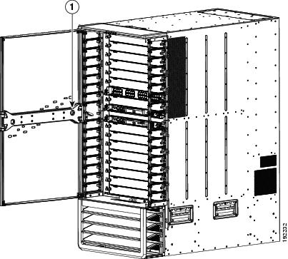
Step 13![]() Open the door handle on the open side of the door until it clicks. This action opens the latches on the open side of the door. See Figure 5-21.
Open the door handle on the open side of the door until it clicks. This action opens the latches on the open side of the door. See Figure 5-21.
Figure 5-21 Attaching the Right Side of the Door
|
|
|
||
|
|
|
Step 14![]() Swing the door closed so that the unused hinge pins fit inside the slots on the top and bottom of the door. When you close the door, the door stopper automatically presses the lock button on the inside of the door so that the door is locked on the hinge pins. If the door stopper does not close the latches, press the door closed at the handle until you hear the latches click. Make sure that the door is fully secured to the frames on both sides.
Swing the door closed so that the unused hinge pins fit inside the slots on the top and bottom of the door. When you close the door, the door stopper automatically presses the lock button on the inside of the door so that the door is locked on the hinge pins. If the door stopper does not close the latches, press the door closed at the handle until you hear the latches click. Make sure that the door is fully secured to the frames on both sides.
Note![]() If a hinge pin is not secured behind a door latch, open the door handle for that side of the door until it clicks, open that side of the door, and then press the door closed so that the pins are positioned all the way inside the door slots. When you close the door, the door stopper automatically closes the door latches. If you do not hear the latches click, press the door at the handle to fully close it and to activate the latches. Test the door to make sure that it is fully secured to the four hinge pins.
If a hinge pin is not secured behind a door latch, open the door handle for that side of the door until it clicks, open that side of the door, and then press the door closed so that the pins are positioned all the way inside the door slots. When you close the door, the door stopper automatically closes the door latches. If you do not hear the latches click, press the door at the handle to fully close it and to activate the latches. Test the door to make sure that it is fully secured to the four hinge pins.
Tip![]() Whenever you need to open the door, pull one of the door handles open until it clicks and then swing that side of the door open.
Whenever you need to open the door, pull one of the door handles open until it clicks and then swing that side of the door open.
Note![]() If the double-hinged door and its holders are not level, it is possible that you will have some difficulty opening or closing the door on one or both sides. The door is not defective. Either push in the bottom portion of the door or slightly lift up the door on that side just before closing. If the problem persists, open the door from the other side, which should be free of this problem, or adjust the cable management system and hinge bracket so that they are level.
If the double-hinged door and its holders are not level, it is possible that you will have some difficulty opening or closing the door on one or both sides. The door is not defective. Either push in the bottom portion of the door or slightly lift up the door on that side just before closing. If the problem persists, open the door from the other side, which should be free of this problem, or adjust the cable management system and hinge bracket so that they are level.
Installing Storage Media in a Supervisor Module
Each supervisor module on a Cisco Nexus 7000 Series switch is shipped with a CompactFlash card installed in the LOG FLASH reader (Supervisor 1 modules) or a USB drive installed in the LOG FLASH reader (Supervisor 2 and Supervisor 2E modules). The EXPANSION FLASH reader (Supervisor 1) or Slot0 port (Supervisor 2 and 2E) is left empty, but you can optionally install a card in that reader or a USB drive in the USB port. To allow this storage media to function with the reader or port, you must make sure that it is either formatted for the reader before installing it or format it after installing it.
Note![]() The LOG FLASH and EXPANSION FLASH or Slot0 readers require different formats for their storage media.
The LOG FLASH and EXPANSION FLASH or Slot0 readers require different formats for their storage media.
To replace an installed CompactFlash card, see the “Replacing Storage Media for a Supervisor Module” section.
To install storage media in a supervisor module, follow these steps:
Step 1![]() Align the storage media to its slot or port on the supervisor module as follows:
Align the storage media to its slot or port on the supervisor module as follows:
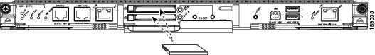
- For a Supervisor 1 module, align the card with the slot for the CompactFlash reader slot labeled LOG FLASH or EXPANSION FLASH as shown in Figure 5-22. The grooves on the thin side of the card are on the end of the card that goes into the reader first. If the card does not fit easily into the reader, flip the card so that the bottom edge is on top, and try pushing the card into the reader.
Figure 5-22 Aligning a CompactFlash Card to its Reader
Step 2![]() Wait for the reader or port LED to turn green and for a message to appear on the console as follows:
Wait for the reader or port LED to turn green and for a message to appear on the console as follows:
- If you are installing a card or USB drive into the log flash reader, the message will end with “logflash:online.”
Make sure that the card or USB drive is fully inserted inside the reader. If it is fully inserted, either format the card (see the Cisco Nexus 7000 Series NX-OS Fundamentals Configuration Guide) or replace the storage media with another that is properly formatted for the reader.
 Feedback