Cisco MDS 9250i Multiservice Fabric Switch Hardware Installation Guide
Bias-Free Language
The documentation set for this product strives to use bias-free language. For the purposes of this documentation set, bias-free is defined as language that does not imply discrimination based on age, disability, gender, racial identity, ethnic identity, sexual orientation, socioeconomic status, and intersectionality. Exceptions may be present in the documentation due to language that is hardcoded in the user interfaces of the product software, language used based on RFP documentation, or language that is used by a referenced third-party product. Learn more about how Cisco is using Inclusive Language.
- Updated:
- January 22, 2014
Chapter: Connecting the Cisco MDS 9250i Switch
Connecting the Cisco MDS 9250i Switch
This chapter describes how to connect the Cisco MDS 9250i switch and includes these topics:
Connection Guidelines
The Cisco MDS 9250i switch provides the following types of ports:
- Console port—An RS-232 port is used to create a local management connection.
- MGMT 10/100/1000 Ethernet port—An Ethernet port is used to access and manage the switch by IP address, such as through Cisco Data Center Network Manager (DCNM).
- Fibre Channel ports —Fibre Channel ports that are used to connect to the SAN or for in-band management. The FC ports on Cisco MDS 9250i switch support the IBM (FICON) connectivity.
- Fibre Channel over Ethernet— FCoE ports that are used for FCoE connectivity. The FCoE ports of the Cisco MDS 9250i switch cannot be used for traditional Ethernet switching.
- IP Storage ports—IP Storage Services ports that are used for the FCIP or iSCSI connectivity.
- USB drive—A simple interface that allows you to connect to different devices supported by Cisco MDS NX-OS.
This chapter includes the following sections:
- Preparing for Network Connections
- Connecting to the Console Port
- Connecting to the MGMT 10/100/1000 Ethernet Port
- Connecting to a Fibre Channel Port

Preparing for Network Connections
When preparing your site for network connections to the Cisco MDS 9250i switch, consider the following for each type of interface, and obtain all of the required equipment before connecting the ports:
Connecting to the Console Port
The console port, labeled “Console,” is an RS-232 port with an RJ-45 interface. It is an asynchronous (async) serial port; any device connected to this port must be capable of asynchronous transmission.
We recommend that you use this port to create a local management connection to set the IP address and other initial configuration settings before connecting the switch to the network for the first time.
You can use the console port to perform the following functions:
- Configure the Cisco MDS 9250i switch from the CLI.
- Monitor network statistics and errors.
- Configure SNMP agent parameters.
- Download software updates.

Note![]() To connect the console port to a computer terminal, the computer must support VT100 terminal emulation. The terminal emulation software—frequently an application such as HyperTerminal or Procomm Plus—makes communication between the switch and computer possible during setup and configuration.
To connect the console port to a computer terminal, the computer must support VT100 terminal emulation. The terminal emulation software—frequently an application such as HyperTerminal or Procomm Plus—makes communication between the switch and computer possible during setup and configuration.
To connect the console port to a computer terminal, follow these steps:
Step 1![]() Configure the terminal emulator program to match the following default port characteristics:
Configure the terminal emulator program to match the following default port characteristics:
Step 2![]() Connect the supplied RJ-45 to DP-25 female adapter. We recommend that you use the adapter and cable provided with the switch.
Connect the supplied RJ-45 to DP-25 female adapter. We recommend that you use the adapter and cable provided with the switch.
Step 3![]() Connect the console cable (a rollover RJ-45 to RJ-45 cable) to the console port or the RJ-45 to DP-25 adapter (depending on your computer) at the computer serial port.
Connect the console cable (a rollover RJ-45 to RJ-45 cable) to the console port or the RJ-45 to DP-25 adapter (depending on your computer) at the computer serial port.
Connecting to the MGMT 10/100/1000 Ethernet Port
The autosensing 10/100/1000 Ethernet management port is located on the front panel (labeled MGMT ETH), below the Console port. This port is used for out-of-band management of the Cisco MDS 9250i switch.
To connect the MGMT 10/100/1000 Ethernet port to an external hub, switch, or router, follow these steps:
Step 1![]() Connect the appropriate modular cable to the MGMT 10/100/1000 Ethernet port:
Connect the appropriate modular cable to the MGMT 10/100/1000 Ethernet port:
- Use a modular, RJ-45, straight-through UTP cable to connect the MGMT 10/100/1000 Ethernet port to an Ethernet switch port or hub.
- Use a cross-over cable to connect to a router interface.
Step 2![]() Connect the other end of the cable to the device.
Connect the other end of the cable to the device.
Connecting to a Fibre Channel Port
The Fibre Channel ports are compatible with LC-type fiber-optic. You can use these ports to connect to the SAN or for in-band management. For information about configuring the switch for in-band management, see the Cisco MDS 9000 Family NX-OS Fundamentals Configuration Guide.
The Cisco MDS 9000 Family supports both Fibre Channel and Gigabit Ethernet protocols for SFP+ transceivers. Each transceiver must match the transceiver on the other end of the cable, and the cable must not exceed the stipulated cable length for reliable communication. For information on how to get the list of supported SFP+ transceivers for your software release, see the Cisco MDS 9000 Family Release Notes for Cisco MDS NX-OS.

Warning![]() Class 1 laser product. Statement 1008
Class 1 laser product. Statement 1008
Warning![]() Invisible laser radiation may be emitted from disconnected fibers or connectors. Do not stare into beams or view directly with optical instruments. Statement 1051
Invisible laser radiation may be emitted from disconnected fibers or connectors. Do not stare into beams or view directly with optical instruments. Statement 1051
This section provides the following topics:
- Removing and Installing Cables into SFP+ Transceivers
- Maintaining SFP+ Transceivers and Fiber-Optic Cables
Removing and Installing SFP+ Transceivers
Note![]() Use only Cisco SFP+ transceivers on the Cisco MDS 9250i switch. Each Cisco SFP+ transceiver is encoded with model information that enables the switch to verify that the SFP+ transceiver meets the requirements for the switch. For instructions specific to the transceiver type, see the “SFP Transceiver Specifications”.
Use only Cisco SFP+ transceivers on the Cisco MDS 9250i switch. Each Cisco SFP+ transceiver is encoded with model information that enables the switch to verify that the SFP+ transceiver meets the requirements for the switch. For instructions specific to the transceiver type, see the “SFP Transceiver Specifications”.
The Cisco MDS 9000 Family supports SFP+ transceivers with the following two types of latching devices:
- Mylar tab latch (Figure 1-1)
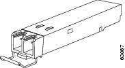
- Bale-clasp latch (Figure 1-2)
Figure 1-1 SFP+ Transceiver with Mylar Tab Latch
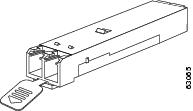
Figure 1-2 SFP+ Transceiver with Bale-Clasp Latch
Removing an SFP+ Transceiver
To remove an SFP+ transceiver, follow these steps:
Step 1![]() Attach an ESD-preventive wrist strap and follow its instructions for use.
Attach an ESD-preventive wrist strap and follow its instructions for use.
Step 2![]() If a cable is installed in the transceiver:
If a cable is installed in the transceiver:
a.![]() Record the cable and port connections for later reference.
Record the cable and port connections for later reference.
b.![]() Press the release latch on the cable, grasp the connector near the connection point, and gently pull the connector from the transceiver.
Press the release latch on the cable, grasp the connector near the connection point, and gently pull the connector from the transceiver.
c.![]() Insert a dust plug into the cable end of the transceiver.
Insert a dust plug into the cable end of the transceiver.
Step 3![]() Remove the transceiver from the port:
Remove the transceiver from the port:
- If the transceiver has a Mylar tab latch, gently pull the tab straight out (do not twist), and then pull the transceiver out of the port.
- If the transceiver has a bale clasp latch, open the clasp by pressing it downwards, and then pull the transceiver out of the port.
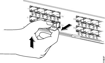
Note![]() If you have difficulty removing a bale clasp SFP+ transceiver, you should reseat the SFP+ by returning the bale clasp in the up position. Then press the SFP+ inward and upward into the cage. Next, lower the bale clasp and pull the SFP+ straight out with a slight upward lifting force (see Figure 1-3). Be careful not to damage the port cage during this process.
If you have difficulty removing a bale clasp SFP+ transceiver, you should reseat the SFP+ by returning the bale clasp in the up position. Then press the SFP+ inward and upward into the cage. Next, lower the bale clasp and pull the SFP+ straight out with a slight upward lifting force (see Figure 1-3). Be careful not to damage the port cage during this process.
Figure 1-3 Alternate Removal Method for Bale Clasp SFP+ Transceivers
Step 4![]() Insert a dust cover into the port end of the transceiver and place the transceiver on an antistatic mat or into a static shielding bag if you plan to return it to the factory.
Insert a dust cover into the port end of the transceiver and place the transceiver on an antistatic mat or into a static shielding bag if you plan to return it to the factory.
Step 5![]() If another transceiver is not being installed, protect the optical cage by inserting a clean cover.
If another transceiver is not being installed, protect the optical cage by inserting a clean cover.
Installing an SFP+ Transceiver
To install an SFP+ transceiver, follow these steps:
Step 1![]() Attach an ESD-preventive wrist strap and follow its instructions for use.
Attach an ESD-preventive wrist strap and follow its instructions for use.
Step 2![]() Remove the dust cover from the port cage.
Remove the dust cover from the port cage.
Step 3![]() Remove the dust cover from the port end of the transceiver.
Remove the dust cover from the port end of the transceiver.
Step 4![]() Insert the transceiver into the port:
Insert the transceiver into the port:
- If the transceiver has a Mylar tab, orient the transceiver with the tab on the bottom, and then gently insert the transceiver into the port until it clicks into place.
- If the transceiver has a bale clasp, orient the transceiver with the clasp on the bottom, close the clasp by pushing it up over the transceiver, and then gently insert the transceiver into the port until it clicks into place.
Note![]() If you cannot install the cable into the transceiver, insert or leave the dust plug in the cable end of the transceiver.
If you cannot install the cable into the transceiver, insert or leave the dust plug in the cable end of the transceiver.
Removing and Installing Cables into SFP+ Transceivers
Removing a Cable from an SFP+ Transceiver
To remove the cable, follow these steps:
Step 1![]() Attach an ESD-preventive wrist strap and follow its instructions for use.
Attach an ESD-preventive wrist strap and follow its instructions for use.
Step 2![]() Press the release latch on the cable, grasp the connector near the connection point, and gently pull the connector from the transceiver.
Press the release latch on the cable, grasp the connector near the connection point, and gently pull the connector from the transceiver.
Step 3![]() Insert a dust plug into the cable end of the transceiver.
Insert a dust plug into the cable end of the transceiver.
Step 4![]() Insert a dust plug onto the end of the cable.
Insert a dust plug onto the end of the cable.
Installing a Cable into an SFP+ Transceiver
To install a cable into a transceiver, follow these steps:
Step 1![]() Attach an ESD-preventive wrist strap and follow its instructions for use.
Attach an ESD-preventive wrist strap and follow its instructions for use.
Step 2![]() Remove the dust cover from the connector on the cable.
Remove the dust cover from the connector on the cable.
Step 3![]() Remove the dust cover from the cable end of the transceiver.
Remove the dust cover from the cable end of the transceiver.
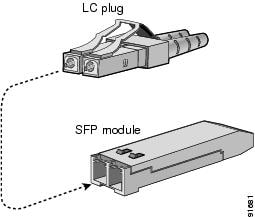
Step 4![]() Align the cable connector with the transceiver and insert the connector into the transceiver until it clicks into place (see Figure 1-4).
Align the cable connector with the transceiver and insert the connector into the transceiver until it clicks into place (see Figure 1-4).
Figure 1-4 Connecting the LC-Type Cable to a Fibre Channel Port
For instructions on verifying connectivity, see the Cisco MDS 9000 Family NX-OS Fundamentals Configuration Guide.
Maintaining SFP+ Transceivers and Fiber-Optic Cables
SFP+ transceivers and fiber-optic cables must be kept clean and dust-free to maintain high signal accuracy and prevent damage to the connectors. Attenuation (loss of light) is increased by contamination and should be below 0.35 dB.
Follow these maintenance guidelines:
- SFP+ transceivers are static sensitive. To prevent ESD damage, wear an ESD-preventive wrist strap that is connected to the chassis.
- Do not remove and insert a transceiver more often than is necessary. Repeated removals and insertions can shorten its useful life.
- Keep all optical connections covered when not in use. If they become dusty, clean before using to prevent dust from scratching the fiber-optic cable ends.
- Do not touch ends of connectors to prevent fingerprints and other contamination.
- Clean regularly; the required frequency of cleaning depends upon the environment. In addition, clean connectors if they are exposed to dust or accidentally touched. Both wet and dry cleaning techniques can be effective; refer to your site’s fiber-optic connection cleaning procedure.
- Inspect routinely for dust and damage. If damage is suspected, clean and then inspect fiber ends under a microscope to determine if damage has occurred.
 Feedback