- New and Changed
- Preface
- Overview
- Using the CFS Infrastructure
- Configuring System Message Logging
- Configuring Call Home
- Scheduling Maintenance Jobs
- Monitoring System Processes and Logs
- Configuring SNMP
- Configuring RMON
- Configuring Domain Parameters
- Monitoring Network Traffic Using SPAN
- Configuring Fabric Configuration Server
Cisco Fabric Manager System Management Configuration Guide
Bias-Free Language
The documentation set for this product strives to use bias-free language. For the purposes of this documentation set, bias-free is defined as language that does not imply discrimination based on age, disability, gender, racial identity, ethnic identity, sexual orientation, socioeconomic status, and intersectionality. Exceptions may be present in the documentation due to language that is hardcoded in the user interfaces of the product software, language used based on RFP documentation, or language that is used by a referenced third-party product. Learn more about how Cisco is using Inclusive Language.
- Updated:
- September 6, 2011
Chapter: Configuring Call Home
- Call Home Features
- About Smart Call Home
- Obtaining Smart Call Home
- Configuring Call Home
- Configuring Contact Information
- Destination Profiles
- Alert Groups
- Customized Alert Group Messages
- Call Home Message Level Feature
- Syslog-Based Alerts
- RMON-Based Alerts
- E-Mail Options
- HTTPS Support
- Periodic Inventory Notification
- Duplicate Message Throttle
- Call Home Enable Function
- Call Home Configuration Distribution
- Call Home Communications Test
- Clearing Call Home Name Server Database
- Configuring EMC E-mail Home Delayed Traps
- Sample Syslog Alert Notification in Full-txt Format
- Sample Syslog Alert Notification in XML Format
- Sample RMON Notification in XML Format
- Event Triggers
- Call Home Message Levels
- Message Contents
- Default Settings
Configuring Call Home
Call Home provides e-mail-based notification of critical system events. A versatile range of message formats are available for optimal compatibility with pager services, standard e-mail, or XML-based automated parsing applications. Common uses of this feature may include direct paging of a network support engineer, e-mail notification to a Network Operations Center, and utilization of Cisco Smart Call Home services for direct case generation with the Technical Assistance Center.
 |
Note http://www.cisco.com/go/smartcall/ |
The Call Home feature provides message throttling capabilities. Periodic inventory messages, port syslog messages, and RMON alert messages are added to the list of deliverable Call Home messages. If required you can also use the Cisco Fabric Services application to distribute the Call Home configuration to all other switches in the fabric.
This chapter includes the following sections:
•![]() Configuring Contact Information
Configuring Contact Information
•![]() Customized Alert Group Messages
Customized Alert Group Messages
•![]() Call Home Message Level Feature
Call Home Message Level Feature
•![]() Periodic Inventory Notification
Periodic Inventory Notification
•![]() Call Home Configuration Distribution
Call Home Configuration Distribution
•![]() Call Home Communications Test
Call Home Communications Test
•![]() Clearing Call Home Name Server Database
Clearing Call Home Name Server Database
•![]() Configuring EMC E-mail Home Delayed Traps
Configuring EMC E-mail Home Delayed Traps
Call Home Features
The Call Home functionality is available directly through the Cisco MDS 9000 Family. It provides multiple Call Home profiles (also referred to as Call Home destination profiles), each with separate potential destinations. You can define your own destination profiles in addition to predefined profiles.
The Call Home function can even leverage support from Cisco Systems or another support partner. Flexible message delivery and format options make it easy to integrate specific support requirements.
The Call Home feature offers the following advantages:
•![]() Fixed set of predefined alerts and trigger events on the switch.
Fixed set of predefined alerts and trigger events on the switch.
•![]() Automatic execution and attachment of relevant command output.
Automatic execution and attachment of relevant command output.
•![]() Multiple message format options:
Multiple message format options:
–![]() Short Text—Suitable for pagers or printed reports.
Short Text—Suitable for pagers or printed reports.
–![]() Plain Text—Full formatted message information suitable for human reading.
Plain Text—Full formatted message information suitable for human reading.
–![]() XML—Matching readable format using Extensible Markup Language (XML) and document type definitions (DTDs) named Messaging Markup Language (MML). The MML DTD is published on the Cisco.com website at http://www.cisco.com/. The XML format enables communication with the Cisco Systems Technical Assistance Center.
XML—Matching readable format using Extensible Markup Language (XML) and document type definitions (DTDs) named Messaging Markup Language (MML). The MML DTD is published on the Cisco.com website at http://www.cisco.com/. The XML format enables communication with the Cisco Systems Technical Assistance Center.
•![]() Multiple concurrent message destinations. You can configure up to 50 e-mail destination addresses for each destination profile.
Multiple concurrent message destinations. You can configure up to 50 e-mail destination addresses for each destination profile.
•![]() Multiple message categories including system, environment, switching module hardware, supervisor module, hardware, inventory, syslog, RMON, and test.
Multiple message categories including system, environment, switching module hardware, supervisor module, hardware, inventory, syslog, RMON, and test.
About Smart Call Home
Smart Call Home is a component of Cisco SMARTnet Service that offers proactive diagnostics, real-time alerts, and personalized web-based reports on select Cisco devices.
Smart Call Home provides fast resolution of system problems by analyzing Call Home messages sent from your devices and providing a direct notification path to Cisco customer support.
Smart Call Home offers the following features:
•![]() Continuous device health monitoring and real-time diagnostics alerts.
Continuous device health monitoring and real-time diagnostics alerts.
•![]() Analysis of Call Home messages from your device and where appropriate, automatic service request generation, routed to the appropriate TAC team, including detailed diagnostic information to speed problem resolution.
Analysis of Call Home messages from your device and where appropriate, automatic service request generation, routed to the appropriate TAC team, including detailed diagnostic information to speed problem resolution.
•![]() Secure message transport through a downloadable Transport Gateway (TG) aggregation point. You can use a TG aggregation point in cases requiring support for multiple devices or in cases where security requirements mandate that your devices not be connected directly to the Internet.
Secure message transport through a downloadable Transport Gateway (TG) aggregation point. You can use a TG aggregation point in cases requiring support for multiple devices or in cases where security requirements mandate that your devices not be connected directly to the Internet.
•![]() Web-based access to Call Home messages and recommendations, inventory and configuration information for all Call Home devices. Provides access to associated Field Notices, Security Advisories and End-of-Life Information.
Web-based access to Call Home messages and recommendations, inventory and configuration information for all Call Home devices. Provides access to associated Field Notices, Security Advisories and End-of-Life Information.
Table 4-1 lists the benefits of Smart Call Home.
Obtaining Smart Call Home
If you have a service contract directly with Cisco Systems, you can receive automatic case generation from the Technical Assistance Center by registering with the Smart Call Home service.
You need the following items to register:
•![]() The SMARTnet contract number for your switch.
The SMARTnet contract number for your switch.
•![]() Your e-mail address
Your e-mail address
•![]() Your Cisco.com ID
Your Cisco.com ID
For detailed information on Smart Call Home, including quick start configuration and registration steps, see the Smart Call Home page at this location:
http://www.cisco.com/go/smartcall/
Configuring Call Home
How you configure the Call Home process depends on how you intend to use the feature. Some points to consider include:
•![]() An e-mail server and at least one destination profile (predefined or user-defined) must be configured. The destination profile(s) used depends on whether the receiving entity is a pager, e-mail, or automated service such as Cisco Smart Call Home.
An e-mail server and at least one destination profile (predefined or user-defined) must be configured. The destination profile(s) used depends on whether the receiving entity is a pager, e-mail, or automated service such as Cisco Smart Call Home.
•![]() Switches can forward events (SNMP traps/informs) up to 10 destinations.
Switches can forward events (SNMP traps/informs) up to 10 destinations.
•![]() The contact name (SNMP server contact), phone, and street address information must be configured before Call Home is enabled. This configuration is required to determine the origin of messages received.
The contact name (SNMP server contact), phone, and street address information must be configured before Call Home is enabled. This configuration is required to determine the origin of messages received.
•![]() The Cisco MDS 9000 switch must have IP connectivity to an e-mail server.
The Cisco MDS 9000 switch must have IP connectivity to an e-mail server.
•![]() If Cisco Smart Call Home is used, an active service contract must cover the device being configured.
If Cisco Smart Call Home is used, an active service contract must cover the device being configured.
To configure Call Home, follow these steps:
Step 1 ![]() Assign contact information.
Assign contact information.
Step 2 ![]() Configure destination profiles.
Configure destination profiles.
Step 3 ![]() Associate one or more alert groups to each profile as required by your network. Customize the alert groups, if desired.
Associate one or more alert groups to each profile as required by your network. Customize the alert groups, if desired.
Step 4 ![]() Configure e-mail options.
Configure e-mail options.
Step 5 ![]() Enable or disable Call Home.
Enable or disable Call Home.
Step 6 ![]() Test Call Home messages.
Test Call Home messages.
Configuring Contact Information
Each switch must include e-mail, phone, and street address information. You can optionally include the contract ID, customer ID, site ID, and switch priority information.
|
Note |
To assign the contact information using Fabric Manager, follow these steps:
Step 1 ![]() In the Fabric Manager Physical Attributes pane, expand Switches, expand Events, and select Call Home.
In the Fabric Manager Physical Attributes pane, expand Switches, expand Events, and select Call Home.
You see the Call Home tabs in the Information pane (see Figure 4-1).
Figure 4-1 Call Home in Fabric Manager
Step 2 ![]() In Device Manager, click Admin > Events > Call Home. See Figure 4-2.
In Device Manager, click Admin > Events > Call Home. See Figure 4-2.
Figure 4-2 Call Home in Device Manager
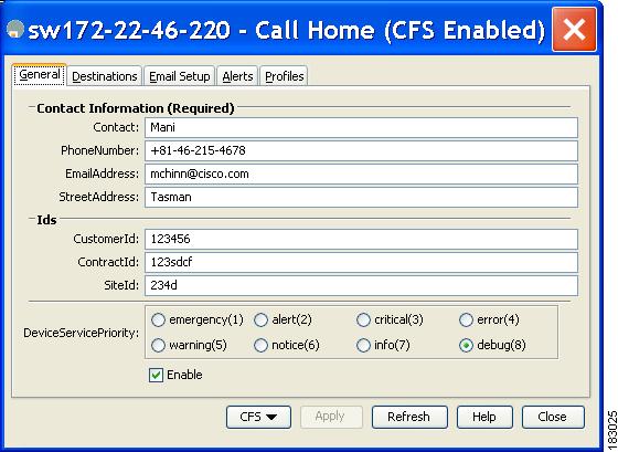
Step 3 ![]() Click the General tab, then assign contact information and enable the Call Home feature. Call Home is not enabled by default. You must enter an e-mail address that identifies the source of Call Home notifications.
Click the General tab, then assign contact information and enable the Call Home feature. Call Home is not enabled by default. You must enter an e-mail address that identifies the source of Call Home notifications.
Step 4 ![]() Click the Destination(s) tab to configure the destination e-mail addresses for Call Home notifications. You can identify one or more e-mail addresses that will receive Call Home notifications.
Click the Destination(s) tab to configure the destination e-mail addresses for Call Home notifications. You can identify one or more e-mail addresses that will receive Call Home notifications.
|
Note |
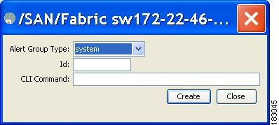
a. ![]() Click the Create tab to create a new destination. You will see the create destination window as shown Figure 4-3.
Click the Create tab to create a new destination. You will see the create destination window as shown Figure 4-3.
Figure 4-3 Create Destination Window

b. ![]() Enter the profile name, ID and type of destination. You can select email or http in the Type field.
Enter the profile name, ID and type of destination. You can select email or http in the Type field.
If you select email, you can enter the e-mail address in the EmailAddress field. The HttpUrl field is disabled.
If you select http, you can enter the HTTP URL in the HttpUrl field. The EmailAddress field is disabled.
c. ![]() Click Create to complete the destination profile creation.
Click Create to complete the destination profile creation.
Step 5 ![]() Click the e-mail Setup tab to identify the SMTP server. Identify a message server to which your switch has access. This message server will forward the Call Home notifications to the destinations.
Click the e-mail Setup tab to identify the SMTP server. Identify a message server to which your switch has access. This message server will forward the Call Home notifications to the destinations.
Step 6 ![]() In Fabric Manager, click the Apply Changes icon. In Device Manager, click Apply.
In Fabric Manager, click the Apply Changes icon. In Device Manager, click Apply.
Destination Profiles
A destination profile contains the required delivery information for an alert notification. Destination profiles are typically configured by the network administrator. At least one destination profile is required. You can configure multiple destination profiles of one or more types.
You can use one of the predefined destination profiles or define a desired profile. If you define a new profile, you must assign a profile name.
|
Note |
You can configure the following attributes for a destination profile:
•![]() Profile name—A string that uniquely identifies each user-defined destination profile and is limited to 32 alphanumeric characters. The format options for a user-defined destination profile are full-txt, short-txt, or XML (default).
Profile name—A string that uniquely identifies each user-defined destination profile and is limited to 32 alphanumeric characters. The format options for a user-defined destination profile are full-txt, short-txt, or XML (default).
•![]() Destination address—The actual address, pertinent to the transport mechanism, to which the alert should be sent.
Destination address—The actual address, pertinent to the transport mechanism, to which the alert should be sent.
•![]() Message formatting—The message format used for sending the alert (full text, short text, or XML).
Message formatting—The message format used for sending the alert (full text, short text, or XML).
To configure predefined destination profile messaging options using Fabric Manager, follow these steps:
Step 1 ![]() Expand Switches, expand Events, and select Call Home in the Physical Attributes pane.
Expand Switches, expand Events, and select Call Home in the Physical Attributes pane.
|
Note |
Step 2 ![]() Click the Profiles tab in the Information pane.
Click the Profiles tab in the Information pane.
You see the Call Home profiles for multiple switches shown in Figure 4-4.
Figure 4-4 Call Home Profiles for Multiple Switches

Step 3 ![]() Set the profile name, message format, message size, and severity level.
Set the profile name, message format, message size, and severity level.
Step 4 ![]() Click in the Alert Groups column and select or remove an alert group.
Click in the Alert Groups column and select or remove an alert group.
Step 5 ![]() Click the Apply Changes icon to create this profile on the selected switches.
Click the Apply Changes icon to create this profile on the selected switches.
To configure a new destination-profile (and related parameters) using Fabric Manager, follow these steps:
Step 1 ![]() Expand Switches, expand Events, and select Call Home in the Physical Attributes pane.
Expand Switches, expand Events, and select Call Home in the Physical Attributes pane.
|
Note |
Step 2 ![]() Click the Profiles tab in the Information pane.
Click the Profiles tab in the Information pane.
You see Call Home profiles for multiple switches.
Figure 4-5 Call Home Profiles for Multiple Switches
Step 3 ![]() Click the Create Row icon to add a new profile.
Click the Create Row icon to add a new profile.
Step 4 ![]() Set the profile name, message format, size, and severity level.
Set the profile name, message format, size, and severity level.
Step 5 ![]() Click an alert group and select each group that you want sent in this profile.
Click an alert group and select each group that you want sent in this profile.
Step 6 ![]() Click a transport method. You can select email, http or emailandhttp.
Click a transport method. You can select email, http or emailandhttp.
Step 7 ![]() Click Create to create this profile on the selected switches.
Click Create to create this profile on the selected switches.
Alert Groups
An alert group is a predefined subset of Call Home alerts supported in all switches in the Cisco MDS 9000 Family. Different types of Call Home alerts are grouped into different alert groups depending on their type. You can associate one or more alert groups to each profile as required by your network.
The alert group feature allows you to select the set of Call Home alerts to be received by a destination profile (either predefined or user-defined). You can associate multiple alert groups with a destination profile.
|
Note |
To associate an alert group with a destination profile using Fabric Manager, follow these steps:
Step 1 ![]() Expand Switches, expand Events, and select Call Home in the Physical Attributes pane.
Expand Switches, expand Events, and select Call Home in the Physical Attributes pane.
Step 2 ![]() Click the Profiles tab in the Information pane.
Click the Profiles tab in the Information pane.
You see the Call Home profiles for multiple switches shown in Figure 4-6.
Figure 4-6 Call Home Profiles for Multiple Switches
Step 3 ![]() Click the Alert Groups column in the row for the profile you want to associate.
Click the Alert Groups column in the row for the profile you want to associate.
You see the alert groups drop-down menu shown in Figure 4-7.
Figure 4-7 Alert Groups Drop-down Menu

Step 4 ![]() Click an alert group to select it for association.
Click an alert group to select it for association.
Step 5 ![]() You see a check next to that alert group. To deselect it and remove the check, click it again.
You see a check next to that alert group. To deselect it and remove the check, click it again.
Step 6 ![]() Click the Apply Changes icon.
Click the Apply Changes icon.
Customized Alert Group Messages
The predefined Call Home alert groups generate notification messages when certain events occur on the switch. You can customize predefined alert groups to execute additional valid show commands when specific events occur. The output from these additional show commands is included in the notification message along with the output of the predefined show commands.
|
Note |
|
Note |
To assign show commands to be executed when an alert is sent, you must associate the commands with the alert group. When an alert is sent, Call Home associates the alert group with an alert type and attaches the output of the show commands to the alert message.
|
Note |
Customizing Alert Group Messages Using Fabric Manager
To customize Call Home alert group messages using Fabric Manager, follow these steps:
Step 1 ![]() Expand Switches, expand Events, and select Call Home in the Physical Attributes pane.
Expand Switches, expand Events, and select Call Home in the Physical Attributes pane.
Step 2 ![]() Click the User Defined Command tab in the Information pane.
Click the User Defined Command tab in the Information pane.
You see the User Defined Command information shown in Figure 4-8.
Figure 4-8 User Defined Command Dialog Box
Step 3 ![]() Click the Create Row icon.
Click the Create Row icon.
Step 4 ![]() Check the check boxes in front of the switches from which you want to receive alerts.
Check the check boxes in front of the switches from which you want to receive alerts.
Step 5 ![]() Select the alert group type from the Alert Group Type drop-down list.
Select the alert group type from the Alert Group Type drop-down list.
Step 6 ![]() Select the ID (1-5) of the CLI command. The ID is used to keep track of the messages.
Select the ID (1-5) of the CLI command. The ID is used to keep track of the messages.
Step 7 ![]() Enter the CLI show command in the CLI Command field.
Enter the CLI show command in the CLI Command field.
Step 8 ![]() Click Create.
Click Create.
Step 9 ![]() Repeat Steps 3 through 7 for each command you want to associate with the profile.
Repeat Steps 3 through 7 for each command you want to associate with the profile.
Step 10 ![]() Click Close to close the dialog box.
Click Close to close the dialog box.
Call Home Message Level Feature
The Call Home message level feature allows you to filter messages based on their level of urgency. Each destination profile (predefined and user-defined) is associated with a Call Home message level threshold. Any message with a value lower than the urgency threshold is not sent. The urgency level ranges from 0 (lowest level of urgency) to 9 (highest level of urgency), and the default is 0 (all messages are sent).
|
Note |
Setting the Call Home Message Levels Using Fabric Manager
To set the message level for each destination profile for Call Home using Fabric Manager, follow these steps:
Step 1 ![]() In Fabric Manager, expand the Switches folder in the Physical Attributes pane, expand Events and then select Call Home.
In Fabric Manager, expand the Switches folder in the Physical Attributes pane, expand Events and then select Call Home.
You see the Call Home information in the Information pane.
In Device Manager, choose Admin > Events > Call Home.
Step 2 ![]() Click the Profiles tab in the Information Pane.
Click the Profiles tab in the Information Pane.
You see the Call Home profiles shown in Figure 4-9.
Figure 4-9 Call Home Profiles
Step 3 ![]() Set a message level for each switch using the drop-down menu in the MsgLevel column.
Set a message level for each switch using the drop-down menu in the MsgLevel column.
Step 4 ![]() Click the Apply Changes icon to save your changes.
Click the Apply Changes icon to save your changes.
Syslog-Based Alerts
You can configure the switch to send certain syslog messages as Call Home messages. The syslog-group-port alert group selects syslog messages for the port facility. The Call Home application maps the syslog severity level to the corresponding Call Home severity level (see the "Call Home Message Levels" section). For example, if you select level 5 for the Call Home message level, syslog messages at levels 0, 1, and 2 are included in the Call Home log.
Whenever a syslog message is generated, the Call Home application sends a Call Home message depending on the mapping between the destination profile and the alert group mapping and based on the severity level of the generated syslog message. To receive a syslog-based Call Home alert, you must associate a destination profile with the syslog alert groups (currently there is only one syslog alert group—syslog-group-port) and configure the appropriate message level (see the "Call Home Message Level Feature" section).
|
Note |
Configuring Syslog-Based Alerts Using Fabric Manager
To configure the syslog-group-port alert group using Fabric Manager, follow these steps:
Step 1 ![]() Select a switch in the Fabric pane.
Select a switch in the Fabric pane.
Step 2 ![]() Expand Switches, expand Events, and select Call Home in the Physical Attributes pane.
Expand Switches, expand Events, and select Call Home in the Physical Attributes pane.
You see the Call Home information in the Information pane.
Step 3 ![]() Click the Profiles tab.
Click the Profiles tab.
You see the Call Home profiles shown in Figure 4-10.
Figure 4-10 Call Home Profiles
Step 4 ![]() Click the Create Row icon.
Click the Create Row icon.
You see the Create Call Home Profile dialog box.
Step 5 ![]() Select the switches for which you want to send alerts.
Select the switches for which you want to send alerts.
Step 6 ![]() Enter the name of the profile in the Name field.
Enter the name of the profile in the Name field.
Step 7 ![]() Choose the message format, message size, and message severity level.
Choose the message format, message size, and message severity level.
Step 8 ![]() Check the syslogGroupPort check box in the AlertGroups section.
Check the syslogGroupPort check box in the AlertGroups section.
Step 9 ![]() Click Create to create the profile for the syslog-based alerts.
Click Create to create the profile for the syslog-based alerts.
Step 10 ![]() Close the dialog box.
Close the dialog box.
RMON-Based Alerts
You can configure the switch to send Call Home notifications corresponding to RMON alert triggers. All RMON-based Call Home messages have their message level set to NOTIFY (2). The RMON alert group is defined for all RMON-based Call Home alerts. To receive an RMON-based Call Home alert, you must associate a destination profile with the RMON alert group.
Configuring RMON Alerts Using Fabric Manager
To configure RMON alert groups using Fabric Manager, follow these steps:
Step 1 ![]() Select a switch in the Fabric pane.
Select a switch in the Fabric pane.
Step 2 ![]() Expand Switches, expand Events, and select Call Home in the Physical Attributes pane.
Expand Switches, expand Events, and select Call Home in the Physical Attributes pane.
You see the Call Home information in the Information pane.
Step 3 ![]() Click the Profiles tab.
Click the Profiles tab.
You see the Call Home profiles shown in Figure 4-11.
Figure 4-11 Call Home Profiles
Step 4 ![]() Select the Create Row icon.
Select the Create Row icon.
You see the Create Call Home Profile dialog box.
Step 5 ![]() Select switches to send alerts.
Select switches to send alerts.
Step 6 ![]() Enter the name of the profile.
Enter the name of the profile.
Step 7 ![]() Select the message format, message size, and message severity level.
Select the message format, message size, and message severity level.
Step 8 ![]() Check the RMON check box in the AlertGroups section.
Check the RMON check box in the AlertGroups section.
Step 9 ![]() Click Create to create the profile for the RMON-based alerts.
Click Create to create the profile for the RMON-based alerts.
Step 10 ![]() Close the dialog box.
Close the dialog box.
E-Mail Options
You can configure the from, reply-to, and return-receipt e-mail addresses. While most e-mail address configurations are optional, you must configure the SMTP server address for the Call Home functionality to work.
Configuring General E-Mail Options Using Fabric Manager
To configure general e-mail options using Fabric Manager, follow these steps:
Step 1 ![]() Select a switch in the Fabric pane.
Select a switch in the Fabric pane.
Step 2 ![]() Expand Switches, expand Events, and select Call Home in the Physical Attributes pane.
Expand Switches, expand Events, and select Call Home in the Physical Attributes pane.
You see the Call Home information in the Information pane.
Step 3 ![]() Click the e-mail Setup tab.
Click the e-mail Setup tab.
Figure 4-12 Call Home e-mail Setup Tab

Step 4 ![]() Select a switch in the Information pane.
Select a switch in the Information pane.
Step 5 ![]() Enter the general e-mail information.
Enter the general e-mail information.
Step 6 ![]() Enter the SMTP server IP address type, IP address or name, and port.
Enter the SMTP server IP address type, IP address or name, and port.
Step 7 ![]() Click the Apply Changes icon to update the e-mail options.
Click the Apply Changes icon to update the e-mail options.
HTTPS Support
The HTTPS support for Call Home provides a transport method called HTTP. HTTPS support is used for a secure communication, and HTTP is used for nonsecure communication. You can configure an HTTP URL for the Call Home destination profile as a destination. The URL link can be from a secure server or nonsecure server. For a destination profile configured with the HTTP URL, the Call Home message is posted to the HTTP URL link.
|
Note |
Periodic Inventory Notification
You can configure the switch to periodically send a message with an inventory of all the software services currently enabled and running on the switch along with hardware inventory information. The inventory is modified each time the switch is restarted nondisruptively.
By default, this feature is disabled in all switches in the Cisco MDS 9000 Family. When you enable this feature without configuring an interval value, the Call Home message is sent every 7 days. This value ranges from 1 to 30 days.
Enabling Periodic Inventory Notifications Using Fabric Manager
To enable periodic inventory notification in a Cisco MDS 9000 Family switch using Fabric Manager, follow these steps:
Step 1 ![]() Select a switch in the Fabric pane.
Select a switch in the Fabric pane.
Step 2 ![]() Expand Switches, expand Events, and select Call Home in the Physical Attributes pane.
Expand Switches, expand Events, and select Call Home in the Physical Attributes pane.
You see the Call Home information in the Information pane.
Step 3 ![]() Click the Periodic Inventory tab.
Click the Periodic Inventory tab.
You see the Call Home periodic inventory information shown in Figure 4-13.
Figure 4-13 Call Home Periodic Inventory Tab
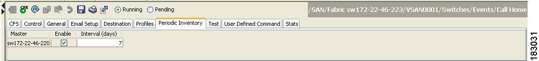
Step 4 ![]() Select a switch in the Information pane.
Select a switch in the Information pane.
Step 5 ![]() Check the Enable check box.
Check the Enable check box.
Step 6 ![]() Enter the number of days for which you want the inventory checked.
Enter the number of days for which you want the inventory checked.
Step 7 ![]() Click the Apply Changes icon.
Click the Apply Changes icon.
Duplicate Message Throttle
You can configure a throttling mechanism to limit the number of Call Home messages received for the same event. If the same message is sent multiple times from the switch within a short period of time, you may be swamped with a large number of duplicate messages.
By default, this feature is enabled in all switches in the Cisco MDS 9000 Family. When enabled, if the number of messages sent exceeds the maximum limit of 30 messages within the 2-hour time frame, then additional messages for that alert type are discarded within that time frame. You cannot modify the time frame or the message counter limit.
If 2 hours have elapsed since the first such message was sent and a new message has to be sent, then the new message is sent and the time frame is reset to the time when the new message was sent and the count is reset to 1.
Enabling Message Throttling Using Fabric Manager
To enable message throttling in a Cisco MDS 9000 Family switch using Fabric Manager, follow these steps:
Step 1 ![]() Select a switch in the Fabric pane.
Select a switch in the Fabric pane.
Step 2 ![]() Expand Switches, expand Events, and select Call Home in the Physical Attributes pane.
Expand Switches, expand Events, and select Call Home in the Physical Attributes pane.
You see the Call Home information in the Information pane.
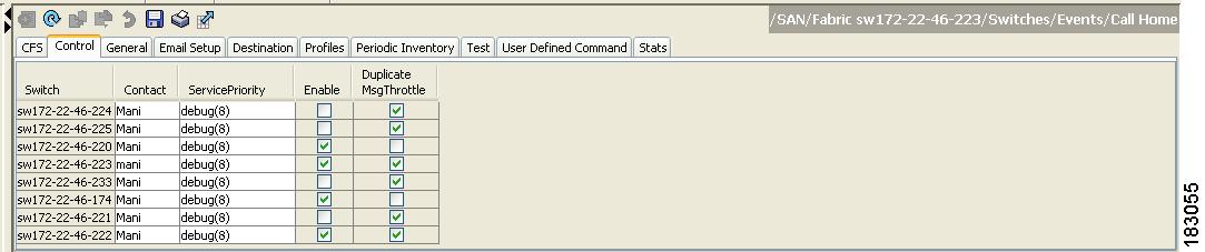
Step 3 ![]() Click the Control tab.
Click the Control tab.
You see the information shown in Figure 4-14.
Figure 4-14 Call Home Control Tab
Step 4 ![]() Select a switch in the Information pane.
Select a switch in the Information pane.
Step 5 ![]() Check the Duplicate Message Throttle check box.
Check the Duplicate Message Throttle check box.
Step 6 ![]() Click the Apply Changes icon.
Click the Apply Changes icon.
Call Home Enable Function
Once you have configured the contact information, you must enable the Call Home function.
Enabling Call Home Using Fabric Manager
To enable the Call Home function using Fabric Manager, follow these steps:
Step 1 ![]() Select a switch in the Fabric pane.
Select a switch in the Fabric pane.
Step 2 ![]() Expand Switches, expand Events, and select Call Home in the Physical Attributes pane.
Expand Switches, expand Events, and select Call Home in the Physical Attributes pane.
You see the Call Home information in the Information pane.
Step 3 ![]() Click the Control tab.
Click the Control tab.
You see the information shown in Figure 4-15.
Figure 4-15 Call Home Control Tab
Step 4 ![]() Select a switch in the Information pane.
Select a switch in the Information pane.
Step 5 ![]() Check the Enable check box.
Check the Enable check box.
Step 6 ![]() Click the Apply Changes icon.
Click the Apply Changes icon.
Call Home Configuration Distribution
You can enable fabric distribution for all Cisco MDS switches in the fabric. When you perform Call Home configurations, and distribution is enabled, that configuration is distributed to all the switches in the fabric.
You automatically acquire a fabric-wide lock when you perform the first configuration operation after you enabled distribution in a switch. The Call Home application uses the effective and pending database model to store or commit the configuration changes. When you commit the configuration changes, the effective database is overwritten by the configuration changes in the pending database and all the switches in the fabric receive the same configuration. After making the configuration changes, you can choose to discard the changes by aborting the changes instead of committing them. In either case, the lock is released. See Chapter 2 "Using the CFS Infrastructure"Using the CFS Infrastructure for more information on the CFS application.
|
Note |
Enabling Call Home Fabric Distribution Using Fabric Manager
To enable Call Home fabric distribution using Fabric Manager, follow these steps:
Step 1 ![]() Select a switch in the Fabric pane.
Select a switch in the Fabric pane.
Step 2 ![]() Expand Switches, expand Events, and select Call Home in the Physical Attributes pane.
Expand Switches, expand Events, and select Call Home in the Physical Attributes pane.
You see the Call Home information in the Information pane.
Step 3 ![]() Click the CFS tab.
Click the CFS tab.
You see the CFS information for Call Home shown in Figure 4-16.
Figure 4-16 Call Home CFS Tab

Step 4 ![]() Select a switch in the Information pane.
Select a switch in the Information pane.
Step 5 ![]() Select Enable from the drop-down list in the Admin column in the row for that switch.
Select Enable from the drop-down list in the Admin column in the row for that switch.
Step 6 ![]() Click the Apply Changes icon to commit the changes.
Click the Apply Changes icon to commit the changes.
Fabric Lock Override
If you have performed a Call Home task and have forgotten to release the lock by either committing or discarding the changes, an administrator can release the lock from any switch in the fabric. If the administrator performs this task, your changes to the pending database are discarded and the fabric lock is released.
 |
Tip |
Database Merge Guidelines
See the "CFS Merge Support" section for detailed concepts.
When merging two Call Home databases, follow these guidelines:
•![]() Be aware that the merged database contains the following information:
Be aware that the merged database contains the following information:
–![]() A superset of all the destination profiles from the dominant and subordinate switches that take part in the merge protocol.
A superset of all the destination profiles from the dominant and subordinate switches that take part in the merge protocol.
–![]() The e-mail addresses and alert groups for the destination profiles.
The e-mail addresses and alert groups for the destination profiles.
–![]() Other configuration information (for example, message throttling, periodic inventory) from the switch that existed in the dominant switch before the merge.
Other configuration information (for example, message throttling, periodic inventory) from the switch that existed in the dominant switch before the merge.
•![]() Verify that two destination profiles do not have the same name (even if they have different configuration information) on the subordinate and dominant switches. If they do contain the same name, the merge operation will fail. You must then modify or delete the conflicting destination profile on the required switch.
Verify that two destination profiles do not have the same name (even if they have different configuration information) on the subordinate and dominant switches. If they do contain the same name, the merge operation will fail. You must then modify or delete the conflicting destination profile on the required switch.
Call Home Communications Test
You can test Call Home communications by sending a test message to the configured destination(s) or sending a test inventory message to the configured destination(s).
Testing Call Home Using Fabric Manager
To test the Call Home function and simulate a message generation using Fabric Manager, follow these steps:
Step 1 ![]() Select a switch in the Fabric pane.
Select a switch in the Fabric pane.
Step 2 ![]() Expand Switches, expand Events, and select Call Home in the Physical Attributes pane.
Expand Switches, expand Events, and select Call Home in the Physical Attributes pane.
You see the Call Home information in the Information pane.
Step 3 ![]() Click the Test tab.
Click the Test tab.
You see the configured tests for the switch and the status of the last testing.
Step 4 ![]() Select a switch in the Information pane.
Select a switch in the Information pane.
Step 5 ![]() Select test or testWithInventory from the TestAction drop-down list in the row for that switch.
Select test or testWithInventory from the TestAction drop-down list in the row for that switch.
Step 6 ![]() Click the Apply Changes icon to run the test.
Click the Apply Changes icon to run the test.
Clearing Call Home Name Server Database
When the Call Home name server database is full, a new entry cannot be added. The device is not allowed to come online.
To clear the name server database, increase the database size or perform a cleanup by removing unused devices. A total of 20,000 name server entries are supported.
Configuring EMC E-mail Home Delayed Traps
Fabric Manager can be configured to generate EMC E-mail Home XML e-mail messages. In SAN-OS Release 3.x or earlier, Fabric Manager listens to interface traps and generates EMC E-mail Home e-mail messages. Link traps are generated when an interface goes to down from up or vice versa. For example, if there is a scheduled server reboot, the link goes down and Fabric Manager generates an e-mail notification.
Cisco NX-OS Release 4.1(3) provides the ability to generate a delayed trap so that the number of generated e-mail messages is reduced. This method filters server reboots and avoids generating unnecessary EMC E-mail Home e-mail messages. In NX-OS Release 4.1(3), users have the ability to select the current existing feature or this new delayed trap feature.
Configuring Delayed Traps Using Cisco Fabric Manager
The server.callhome.delayedtrap.enable property is added to section 9 Call Home in the server.properties configuration file. The property file can enable the Fabric Manager server to use delayed traps instead of regular linkDown traps for EMC E-mail Home messages. To enable this feature, you need to turn on delayed traps at switch level, and then set the server.callhome.delayedtrap.enable property in the server.properties configuration file to true. By default, the server.callhome.delayedtrap.enable option is disabled and regular linkDown traps are used.
To enable delayed traps on switches running NX-OS Release 4.1(3) and later using Fabric Manager, follow these steps:
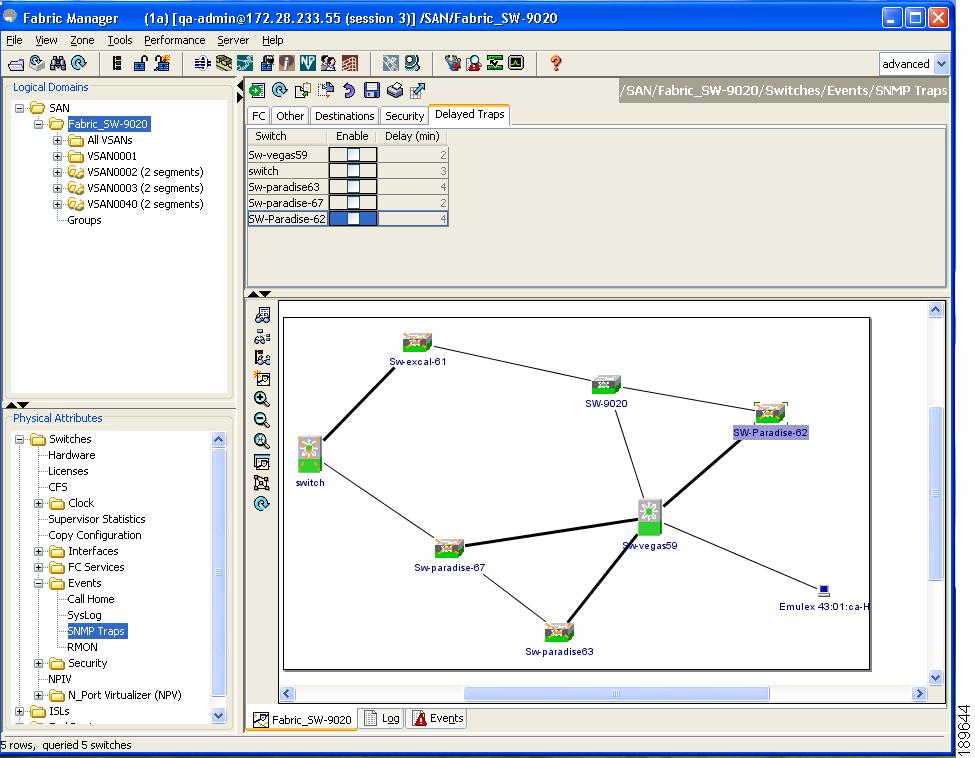
Step 1 ![]() In the Physical Attributes, expand Switches > Events, and select SNMP Traps.
In the Physical Attributes, expand Switches > Events, and select SNMP Traps.
In the table above the map layout in Fabric Manager, click the Delayed Traps tab.
Figure 4-17

Delayed Trap Dialog Box
Step 2 ![]() Check the Enable check box for the switches on which you want to enable delayed traps.
Check the Enable check box for the switches on which you want to enable delayed traps.
Step 3 ![]() Enter the timer value in the Delay column.
Enter the timer value in the Delay column.
Step 4 ![]() Click Apply to save your changes.
Click Apply to save your changes.
|
Note |
To disable delayed traps, follow these steps:
Step 1 ![]() Uncheck the Enable check box.
Uncheck the Enable check box.
Figure 4-18
Delayed Trap Dialog Box
Step 2 ![]() Click Apply.
Click Apply.
Enabling Delayed Traps Using Cisco Device Manager
To enable the delayed traps using Device Manager, follow these steps:
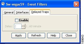
Step 1 ![]() In Device Manager, choose Admin > Events > Filters > Delayed Traps.
In Device Manager, choose Admin > Events > Filters > Delayed Traps.
You can see the Events Filters information in the Information pane.
Step 2 ![]() Click the Delayed Traps tab.
Click the Delayed Traps tab.
Figure 4-19

Delayed Traps Dialog Box
Step 3 ![]() Check the Enable check box to enable delayed traps.
Check the Enable check box to enable delayed traps.
Delay interval will only be available when the feature is enabled.
Step 4 ![]() To disable Delayed Traps, uncheck the Enable check box and click Apply.
To disable Delayed Traps, uncheck the Enable check box and click Apply.
Figure 4-20
Disable Traps Dialog Box
Sample Syslog Alert Notification in Full-txt Format
source:MDS9000
Switch Priority:7
Device Id:DS-C9506@C@FG@07120011
Customer Id:basu
Contract Id:123
Site Id:San Jose
Server Id:DS-C9506@C@FG@07120011
Time of Event:2004-10-08T11:10:44
Message Name:SYSLOG_ALERT
Message Type:Syslog
Severity Level:2
System Name:10.76.100.177
Contact Name:Basavaraj B
Contact e-mail:admin@yourcompany.com
Contact Phone:+91-80-310-1718
Street Address:#71 , Miller's Road
Event Description:2004 Oct  8 11:10:44 10.76.100.177 %PORT-5-IF_TRUNK_UP: %$VSAN 1%$
Interface fc2/5, vsan 1 is up
syslog_facility:PORT
start chassis information:
Affected Chassis:DS-C9506
Affected Chassis Serial Number:FG@07120011
Affected Chassis Hardware Version:0.104
Affected Chassis Software Version:3.1(1)
Affected Chassis Part No:73-8607-01
end chassis information:
Sample Syslog Alert Notification in XML Format
<?xml version="1.0" encoding="UTF-8" ?>
<soap-env:Envelope xmlns:soap-env="http://www.w3.org/2003/05/soap-envelope">
<soap-env:Header>
<aml-session:Session xmlns:aml-session="http://www.cisco.com/2004/01/aml-session"
soap-env:mustUnderstand="true"
soap-env:role="http://www.w3.org/2003/05/soap-envelope/role/next">
<aml-session:To>http://tools.cisco.com/neddce/services/DDCEService</aml-session:To>
<aml-session:Path>
<aml-session:Via>http://www.cisco.com/appliance/uri</aml-session:Via>
</aml-session:Path>
<aml-session:From>http://www.cisco.com/appliance/uri</aml-session:From>
<aml-session:MessageId>1004:FOX090306QT:3E55A81A</aml-session:MessageId>
</aml-session:Session>
</soap-env:Header>
<soap-env:Body>
<aml-block:Block xmlns:aml-block="http://www.cisco.com/2004/01/aml-block">
<aml-block:Header>
<aml-block:Type>http://www.cisco.com/2005/05/callhome/syslog</aml-block:Type>
<aml-block:CreationDate>2003-02-21 04:16:18 GMT+00:00</aml-block:CreationDate>
<aml-block:Builder>
<aml-block:Name>MDS</aml-block:Name>
<aml-block:Version>4.1</aml-block:Version>
</aml-block:Builder>
<aml-block:BlockGroup>
<aml-block:GroupId>1005:FOX090306QT:3E55A81A</aml-block:GroupId>
<aml-block:Number>0</aml-block:Number>
<aml-block:IsLast>true</aml-block:IsLast>
<aml-block:IsPrimary>true</aml-block:IsPrimary>
<aml-block:WaitForPrimary>false</aml-block:WaitForPrimary>
</aml-block:BlockGroup>
<aml-block:Severity>6</aml-block:Severity>
</aml-block:Header>
<aml-block:Content>
<ch:CallHome xmlns:ch="http://www.cisco.com/2005/05/callhome" version="1.0">
<ch:EventTime>2003-02-21 04:16:18 GMT+00:00</ch:EventTime> <ch:MessageDescription>LICENSE_VIOLATION 2003 Feb 21 04:16:18 switch %$ %DAEMON-3-SYSTEM_MSG: <<%LICMGR-3-LOG_LICAPP_NO_LIC>> License file is missing for feature SAN_EXTN_OVER_IP</ch:MessageDescription>
<ch:Event>
<ch:Type>syslog</ch:Type>
<ch:SubType>LICENSE_VIOLATION</ch:SubType>
<ch:Brand>Cisco</ch:Brand>
<ch:Series>MDS9000</ch:Series>
</ch:Event>
<ch:CustomerData>
<ch:UserData>
<ch:e-mail>esajjana@cisco.com</ch:e-mail>
</ch:UserData>
<ch:ContractData>
<ch:CustomerId>eeranna</ch:CustomerId>
<ch:SiteId>Bangalore</ch:SiteId>
<ch:ContractId>123</ch:ContractId>
<ch:DeviceId>DS-C9216I-K9@C@FOX090306QT</ch:DeviceId>
</ch:ContractData>
<ch:SystemInfo>
<ch:Name>switch</ch:Name>
<ch:Contact>Eeranna</ch:Contact>
<ch:Contacte-mail>esajjana@cisco.com</ch:Contacte-mail>
<ch:ContactPhoneNumber>+91-80-310-1718</ch:ContactPhoneNumber>
<ch:StreetAddress>#71, Miller's Road</ch:StreetAddress> </ch:SystemInfo> </ch:CustomerData> <ch:Device> <rme:Chassis xmlns:rme="http://www.cisco.com/rme/4.0">
<rme:Model>DS-C9216I-K9</rme:Model>
<rme:HardwareVersion>1.0</rme:HardwareVersion>
<rme:SerialNumber>FOX090306QT</rme:SerialNumber>
</rme:Chassis>
</ch:Device>
</ch:CallHome>
</aml-block:Content>
<aml-block:Attachments>
<aml-block:Attachment type="inline">
<aml-block:Name>show logging logfile | tail -n 200</aml-block:Name> <aml-block:Data
encoding="plain">
<![CDATA[syslog_show:: command: 1055 param_count: 0
2003 Feb 21 04:11:48 %KERN-2-SYSTEM_MSG: Starting kernel... - kernel
2003 Feb 21 04:11:48 %KERN-3-SYSTEM_MSG: CMOS: Module initialized - kernel
2003 Feb 21 04:11:48 %KERN-2-SYSTEM_MSG: CARD TYPE: KING BB Index = 2344 - kernel
2003 Feb 21 04:12:04  %MODULE-5-ACTIVE_SUP_OK: Supervisor 1 is active (serial:
JAB100700MC)
2003 Feb 21 04:12:04  %PLATFORM-5-MOD_STATUS: Module 1 current-status is
MOD_STATUS_ONLINE/OK
2003 Feb 21 04:12:06  %IMAGE_DNLD-SLOT1-5-ADDON_IMG_DNLD_COMPLETE:  Addon module image
download process completed. Addon Image download completed, installing image please wait..
2003 Feb 21 04:12:07  %IMAGE_DNLD-SLOT1-5-ADDON_IMG_DNLD_SUCCESSFUL:  Addon module image
download and install process successful. Addon image installed.
2003 Feb 21 04:12:08  %KERN-3-SYSTEM_MSG: klm_af_xipc: Unknown parameter `start' -
kernel
2003 Feb 21 04:12:08  %KERN-3-SYSTEM_MSG: klm_ips_portcfg: Unknown parameter `start'
- kernel
2003 Feb 21 04:12:08  %KERN-3-SYSTEM_MSG: klm_flamingo: Unknown parameter `start' -
kernel
2003 Feb 21 04:12:10 %PORT-5-IF_UP: Interface mgmt0 is up
2003 Feb 21 04:12:21 switch %LICMGR-3-LOG_LIC_FILE_MISSING: License file(s) missing for
feature ENTERPRISE_PKG.
2003 Feb 21 04:12:21 switch %LICMGR-3-LOG_LIC_FILE_MISSING: License file(s) missing for
feature SAN_EXTN_OVER_IP.
2003 Feb 21 04:12:21 switch %LICMGR-3-LOG_LIC_FILE_MISSING: License file(s) missing for
feature ENTERPRISE_PKG.
2003 Feb 21 04:12:21 switch %LICMGR-3-LOG_LIC_FILE_MISSING: License file(s) missing for
feature SAN_EXTN_OVER_IP.
2003 Feb 21 04:12:23 switch %PLATFORM-5-MOD_STATUS: Module 1 current-status is
MOD_STATUS_ONLINE/OK
2003 Feb 21 04:12:23 switch %MODULE-5-MOD_OK: Module 1 is online (serial: JAB100700MC)
2003 Feb 21 04:12:25 switch %PORT-5-IF_DOWN_ADMIN_DOWN: %$VSAN 1%$ Interface fc1/1 is down
(Administratively down)
2003 Feb 21 04:12:25 switch %PORT-5-IF_DOWN_ADMIN_DOWN: %$VSAN 1%$ Interface fc1/2 is down
(Administratively down)
2003 Feb 21 04:12:25 switch %PORT-5-IF_DOWN_ADMIN_DOWN: %$VSAN 1%$ Interface fc1/3 is down
(Administratively down)
2003 Feb 21 04:12:25 switch %PORT-5-IF_DOWN_ADMIN_DOWN: %$VSAN 1%$ Interface fc1/4 is down
(Administratively down)
2003 Feb 21 04:12:26 switch %PLATFORM-5-PS_STATUS: PowerSupply 1 current-status is PS_FAIL
2003 Feb 21 04:12:26 switch %PLATFORM-2-PS_FAIL: Power supply 1 failed or shut down
(Serial number QCS1007109F)
2003 Feb 21 04:12:26 switch %PLATFORM-5-PS_FOUND: Power supply 2 found (Serial number
QCS1007109R)
2003 Feb 21 04:12:26 switch %PLATFORM-2-PS_OK: Power supply 2 ok (Serial number
QCS1007109R)
2003 Feb 21 04:12:26 switch %PLATFORM-5-PS_STATUS: PowerSupply 2 current-status is PS_OK
2003 Feb 21 04:12:26 switch %PLATFORM-2-PS_FANOK: Fan in Power supply 2 ok
2003 Feb 21 04:12:26 switch %PLATFORM-5-FAN_DETECT: Fan module 1 (Serial number
NWG0901031X) ChassisFan1 detected
2003 Feb 21 04:12:26 switch %PLATFORM-2-FAN_OK: Fan module ok
2003 Feb 21 04:12:26 switch %PLATFORM-2-CHASSIS_CLKMODOK: Chassis clock module A ok
2003 Feb 21 04:12:26 switch %PLATFORM-2-CHASSIS_CLKSRC: Current chassis clock source is
clock-A
2003 Feb 21 04:12:26 switch %PORT-5-IF_DOWN_ADMIN_DOWN: %$VSAN 1%$ Interface fc1/5 is down
(Administratively down)
2003 Feb 21 04:12:26 switch %PORT-5-IF_DOWN_ADMIN_DOWN: %$VSAN 1%$ Interface fc1/6 is down
(Administratively down)
2003 Feb 21 04:12:26 switch %PORT-5-IF_DOWN_ADMIN_DOWN: %$VSAN 1%$ Interface fc1/7 is down
(Administratively down)
2003 Feb 21 04:12:26 switch %PORT-5-IF_DOWN_ADMIN_DOWN: %$VSAN 1%$ Interface fc1/8 is down
(Administratively down)
2003 Feb 21 04:12:26 switch %PORT-5-IF_DOWN_ADMIN_DOWN: %$VSAN 1%$ Interface fc1/9 is down
(Administratively down)
2003 Feb 21 04:12:26 switch %PORT-5-IF_DOWN_ADMIN_DOWN: %$VSAN 1%$ Interface fc1/10 is
down (Administratively down)
2003 Feb 21 04:12:27 switch %PORT-5-IF_DOWN_ADMIN_DOWN: %$VSAN 1%$ Interface fc1/11 is
down (Administratively down)
2003 Feb 21 04:12:27 switch %PORT-5-IF_DOWN_ADMIN_DOWN: %$VSAN 1%$ Interface fc1/12 is
down (Administratively down)
2003 Feb 21 04:12:27 switch %PORT-5-IF_DOWN_ADMIN_DOWN: %$VSAN 1%$ Interface fc1/13 is
down (Administratively down)
2003 Feb 21 04:12:27 switch %PORT-5-IF_DOWN_ADMIN_DOWN: %$VSAN 1%$ Interface fc1/14 is
down (Administratively down)
2003 Feb 21 04:12:30 switch %PLATFORM-2-MOD_DETECT: Module 2 detected (Serial number
JAB0923016X) Module-Type IP Storage Services Module Model DS-X9304-SMIP
2003 Feb 21 04:12:30 switch %MODULE-2-MOD_UNKNOWN: Module type [25] in slot 2 is not
supported
2003 Feb 21 04:12:45 switch %VSHD-5-VSHD_SYSLOG_CONFIG_I: Configured from vty by root on
console0
2003 Feb 21 04:14:06 switch %VSHD-5-VSHD_SYSLOG_CONFIG_I: Configured from vty by admin on
console0
2003 Feb 21 04:15:12 switch %VSHD-5-VSHD_SYSLOG_CONFIG_I: Configured from vty by admin on
console0
2003 Feb 21 04:15:52 switch %SYSMGR-3-BASIC_TRACE: core_copy: PID 1643 with message Core
not generated by system for licmgr(0). WCOREDUMP(9) returned zero .
2003 Feb 21 04:15:52 switch %SYSMGR-2-SERVICE_CRASHED: Service \"licmgr\" (PID 2272)
hasn't caught signal 9 (no core).
2003 Feb 21 04:16:18 switch %LICMGR-3-LOG_LIC_FILE_MISSING: License file(s) missing for
feature ENTERPRISE_PKG.
2003 Feb 21 04:16:18 switch %LICMGR-3-LOG_LIC_FILE_MISSING: License file(s) missing for
feature SAN_EXTN_OVER_IP.
2003 Feb 21 04:16:18 switch %LICMGR-3-LOG_LIC_FILE_MISSING: License file(s) missing for
feature ENTERPRISE_PKG.
2003 Feb 21 04:16:18 switch %LICMGR-3-LOG_LIC_FILE_MISSING: License file(s) missing for
feature SAN_EXTN_OVER_IP.
2003 Feb 21 04:16:18 switch %CALLHOME-2-EVENT: LICENSE_VIOLATION
2003 Feb 21 04:16:18 switch %CALLHOME-2-EVENT: LICENSE_VIOLATION
2003 Feb 21 04:16:18 switch %CALLHOME-2-EVENT: LICENSE_VIOLATION
2003 Feb 21 04:16:18 switch %CALLHOME-2-EVENT: LICENSE_VIOLATION ]]> </aml-block:Data>
</aml-block:Attachment> <aml-block:Attachment type="inline"> <aml-block:Name>show license
usage</aml-block:Name> <aml-block:Data encoding="plain">
<![CDATA[Feature Ins Lic Status Expiry Date Comments
Count
--------------------------------------------------------------------------------
DMM_184_PKG No 0 Unused Grace expired
FM_SERVER_PKG No - Unused Grace expired
MAINFRAME_PKG No - Unused Grace expired
ENTERPRISE_PKG Yes - Unused never license missing
DMM_FOR_SSM_PKG No 0 Unused Grace expired
SAN_EXTN_OVER_IP Yes 8 Unused never 8 license(s) missing
PORT_ACTIVATION_PKG No 0 Unused -
SME_FOR_IPS_184_PKG No 0 Unused Grace expired
STORAGE_SERVICES_184 No 0 Unused Grace expired
SAN_EXTN_OVER_IP_18_4 No 0 Unused Grace expired
SAN_EXTN_OVER_IP_IPS2 No 0 Unused Grace expired
SAN_EXTN_OVER_IP_IPS4 No 0 Unused Grace expired
STORAGE_SERVICES_SSN16 No 0 Unused Grace expired
10G_PORT_ACTIVATION_PKG No 0 Unused -
STORAGE_SERVICES_ENABLER_PKG No 0 Unused Grace expired
--------------------------------------------------------------------------------
**** WARNING: License file(s) missing. **** ]]> </aml-block:Data> </aml-block:Attachment>
</aml-block:Attachments> </aml-block:Block> </soap-env:Body> </soap-env:Envelope>
Sample RMON Notification in XML Format
<?xml version="1.0" encoding="UTF-8" ?>
<soap-env:Envelope xmlns:soap-env="http://www.w3.org/2003/05/soap-envelope">
<soap-env:Header>
<aml-session:Session xmlns:aml-session="http://www.cisco.com/2004/01/aml-session"
soap-env:mustUnderstand="true"
soap-env:role="http://www.w3.org/2003/05/soap-envelope/role/next">
<aml-session:To>http://tools.cisco.com/neddce/services/DDCEService</aml-session:To>
<aml-session:Path>
<aml-session:Via>http://www.cisco.com/appliance/uri</aml-session:Via>
</aml-session:Path>
<aml-session:From>http://www.cisco.com/appliance/uri</aml-session:From>
<aml-session:MessageId>1086:FHH0927006V:48BA26BD</aml-session:MessageId>
</aml-session:Session>
</soap-env:Header>
<soap-env:Body>
<aml-block:Block xmlns:aml-block="http://www.cisco.com/2004/01/aml-block">
<aml-block:Header>
<aml-block:Type>http://www.cisco.com/2005/05/callhome/diagnostic</aml-block:Type>
<aml-block:CreationDate>2008-08-31 05:06:05 GMT+00:00</aml-block:CreationDate>
<aml-block:Builder>
<aml-block:Name>MDS</aml-block:Name>
<aml-block:Version>4.1</aml-block:Version>
</aml-block:Builder>
<aml-block:BlockGroup>
<aml-block:GroupId>1087:FHH0927006V:48BA26BD</aml-block:GroupId>
<aml-block:Number>0</aml-block:Number>
<aml-block:IsLast>true</aml-block:IsLast>
<aml-block:IsPrimary>true</aml-block:IsPrimary>
<aml-block:WaitForPrimary>false</aml-block:WaitForPrimary>
</aml-block:BlockGroup>
<aml-block:Severity>2</aml-block:Severity>
</aml-block:Header>
<aml-block:Content>
<ch:CallHome xmlns:ch="http://www.cisco.com/2005/05/callhome" version="1.0">
<ch:EventTime>2008-08-31 05:06:05 GMT+00:00</ch:EventTime>
<ch:MessageDescription>RMON_ALERT WARNING(4) Falling:iso.3.6.1.4.1.9.9.305.1.1.1.0=1 <= 89:1, 4</ch:MessageDescription>
<ch:Event>
<ch:Type>diagnostic</ch:Type>
<ch:SubType>GOLD-major</ch:SubType>
<ch:Brand>Cisco</ch:Brand>
<ch:Series>MDS9000</ch:Series>
</ch:Event>
<ch:CustomerData>
<ch:UserData>
<ch:e-mail>mchinn@cisco.com</ch:e-mail>
</ch:UserData>
<ch:ContractData>
<ch:CustomerId>12ss</ch:CustomerId>
<ch:SiteId>2233</ch:SiteId>
<ch:ContractId>rrr55</ch:ContractId>
<ch:DeviceId>DS-C9513@C@FHH0927006V</ch:DeviceId>
</ch:ContractData>
<ch:SystemInfo>
<ch:Name>sw172-22-46-174</ch:Name>
<ch:Contact>Mani</ch:Contact>
<ch:Contacte-mail>mchinn@cisco.com</ch:Contacte-mail>
<ch:ContactPhoneNumber>+1-800-304-1234</ch:ContactPhoneNumber>
<ch:StreetAddress>1234 wwee</ch:StreetAddress>
</ch:SystemInfo>
</ch:CustomerData>
<ch:Device>
<rme:Chassis xmlns:rme="http://www.cisco.com/rme/4.0">
<rme:Model>DS-C9513</rme:Model>
<rme:HardwareVersion>0.205</rme:HardwareVersion>
<rme:SerialNumber>FHH0927006V</rme:SerialNumber>
</rme:Chassis>
</ch:Device>
</ch:CallHome>
</aml-block:Content>
</aml-block:Block>
</soap-env:Body>
</soap-env:Envelope>
Event Triggers
This section discusses Call Home trigger events. Trigger events are divided into categories, with each category assigned CLI commands to execute when the event occurs. The command output is included in the transmitted message. Table 4-2 lists the trigger events.
Table 4-3 lists event categories and command outputs.
Call Home Message Levels
Call Home messages (sent for syslog alert groups) have the syslog severity level mapped to the Call Home message level (see the "Syslog-Based Alerts" section).
This section discusses the severity levels for a Call Home message when using one or more switches in the Cisco MDS 9000 Family. Call Home message levels are preassigned per event type.
Severity levels range from 0 to 9, with 9 having the highest urgency. Each syslog level has keywords and a corresponding syslog level as listed in Table 4-4.
|
Note |
|
Note |
Message Contents
The following contact information can be configured on the switch:
•![]() Name of the contact person
Name of the contact person
•![]() Phone number of the contact person
Phone number of the contact person
•![]() E-mail address of the contact person
E-mail address of the contact person
•![]() Mailing address to which replacement parts must be shipped, if required
Mailing address to which replacement parts must be shipped, if required
•![]() Site ID of the network where the site is deployed
Site ID of the network where the site is deployed
•![]() Contract ID to identify the service contract of the customer with the service provider
Contract ID to identify the service contract of the customer with the service provider
Table 4-5 describes the short text formatting option for all message types.
Table 4-6, Table 4-7, and Table 4-8 display the information contained in plain text and XML messages.
|
(Plain text and XML) |
(Plain text and XML) |
(XML only) |
|---|---|---|
Time stamp |
Date and time stamp of event in ISO time notation: YYYY-MM-DDTHH:MM:SS. Note |
/mml/header/time - ch:EventTime |
Message name |
Name of message. Specific event names are listed in the "Event Triggers" section. |
/mml/header/name |
Message type |
Specifically "Call Home." |
/mml/header/type - ch:Type |
Message group |
Specifically "reactive." |
/mml/header/group |
Severity level |
Severity level of message (see Table 4-4). |
/mml/header/level - aml-block:Severity |
Source ID |
Product type for routing. |
/mml/header/source - ch:Series |
Device ID |
Unique device identifier (UDI) for end device generating message. This field should empty if the message is non-specific to a fabric switch. Format is type@Sid@serial, where: • • • • Example: DS-C9509@C@12345678 |
/mml/ header/deviceId |
Customer ID |
Optional user-configurable field used for contract info or other ID by any support service. |
/mml/header/customerID - ch:CustomerId |
Contract ID |
Optional user-configurable field used for contract info or other ID by any support service. |
/mml/header/contractId - ch:ContractId> |
Site ID |
Optional user-configurable field used for Cisco-supplied site ID or other data meaningful to alternate support service. |
/mml/header/siterId - ch:SiteId |
Server ID |
If the message is generated from the fabric switch, it is the unique device identifier (UDI) of the switch. Format is type@Sid@serial, where: • • • • Example: DS-C9509@C@12345678 |
/mml/header/serverId - -blank- |
Message description |
Short text describing the error. |
/mml/body/msgDesc - ch:MessageDescription |
Device name |
Node that experienced the event. This is the host name of the device. |
/mml/body/sysName - ch:SystemInfo/Name |
Contact name |
Name of person to contact for issues associated with the node experiencing the event. |
/mml/body/sysContact - ch:SystemInfo/Contact |
Contact e-mail |
E-mail address of person identified as contact for this unit. |
/mml/body/sysContacte-mail - ch:SystemInfo/Contacte-mail |
Contact phone number |
Phone number of the person identified as the contact for this unit. |
/mml/body/sysContactPhoneNumber - ch:SystemInfo/ContactPhoneNumber |
Street address |
Optional field containing street address for RMA part shipments associated with this unit. |
/mml/body/sysStreetAddress - ch:SystemInfo/StreetAddress |
Model name |
Model name of the switch. This is the specific model as part of a product family name. |
/mml/body/chassis/name - rme:Chassis/Model |
Serial number |
Chassis serial number of the unit. |
/mml/body/chassis/serialNo - rme:Chassis/SerialNumber |
Chassis part number |
Top assembly number of the chassis. |
/mml/body/fru/partNo - rme:chassis/Card/PartNumber |
Chassis hardware version |
Hardware version of chassis. |
/mml/body/chassis/hwVersion - rme:Chassis/HardwareVersion |
Supervisor module software version |
Top level software version. |
/mml/body/fru/swVersion - rme:chassis/Card/SoftwareIdentity |
Affected FRU name |
Name of the affected FRU generating the event message. |
/mml/body/fru/name - rme:chassis/Card/Model |
Affected FRU serial number |
Serial number of affected FRU. |
/mml/body/fru/serialNo - rme:chassis/Card/SerialNumber |
Affected FRU part number |
Part number of affected FRU. |
/mml/body/fru/partNo - rme:chassis/Card/PartNumber |
FRU slot |
Slot number of FRU generating the event message. |
/mml/body/fru/slot - rme:chassis/Card/LocationWithinContainer |
FRU hardware version |
Hardware version of affected FRU. |
/mml/body/fru/hwVersion - rme:chassis/Card/SoftwareIdentity |
FRU software version |
Software version(s) running on affected FRU. |
/mml/body/fru/swVersion - rme:chassis/Card/SoftwareIdentity |
Command output name |
The exact name of the issued command. |
/mml/attachments/attachment/name - aml-block:Attachment/Name |
Attachment type |
Specifically command output. |
/mml/attachments/attachment/type - aml-block:Attachment type |
MIME type |
Normally text or plain or encoding type. |
/mml/attachments/attachment/mime - aml-block:Attachment/Data encoding |
Command output text |
Output of command automatically executed (see Table 4-3). |
/mml/attachments/attachment/atdata - aml-block:Attachment/Data |
|
(Plain text and XML) |
(Plain text and XML) |
(XML only) |
|---|---|---|
Time stamp |
Date and time stamp of event in ISO time notation: YYYY-MM-DDTHH:MM:SS. Note |
/mml/header/time - ch:EventTime |
Message name |
Name of message. Specifically "Inventory Update" Specific event names are listed in the "Event Triggers" section. |
/mml/header/name |
Message type |
Specifically "Inventory Update." |
/mml/header/type - ch-inv:Type |
Message group |
Specifically "proactive." |
/mml/header/group |
Severity level |
Severity level of inventory event is level 2 (see Table 4-4). |
/mml/header/level - aml-block:Severity |
Source ID |
Product type for routing at Cisco. Specifically "MDS 9000." |
/mml/header/source - ch-inv:Series |
Device ID |
Unique Device Identifier (UDI) for end device generating message. This field should empty if the message is non-specific to a fabric switch. Format is type@Sid@serial, where: • • • • Example: DS-C9509@C@12345678 |
/mml/ header /deviceId |
Customer ID |
Optional user-configurable field used for contact info or other ID by any support service. |
/mml/header/customerID - ch-inv:CustomerId |
Contract ID |
Optional user-configurable field used for contact info or other ID by any support service. |
/mml/header/contractId - ch-inv:ContractId> |
Site ID |
Optional user-configurable field, can be used for Cisco-supplied site ID or other data meaningful to alternate support service. |
/mml/header/siterId - ch-inv:SiteId |
Server ID |
If the message is generated from the fabric switch, it is the Unique device identifier (UDI) of the switch. Format is type@Sid@serial, where: • • • • Example: DS-C9509@C@12345678 |
/mml/header/serverId - -blank- |
Message description |
Short text describing the error. |
/mml/body/msgDesc - ch-inv:MessageDescription |
Device name |
Node that experienced the event. |
/mml/body/sysName - ch-inv:SystemInfo/Name |
Contact name |
Name of person to contact for issues associated with the node experiencing the event. |
/mml/body/sysContact - ch-inv:SystemInfo/Contact |
Contact e-mail |
E-mail address of person identified as contact for this unit. |
/mml/body/sysContacte-mail - ch-inv:SystemInfo/Contacte-mail |
Contact phone number |
Phone number of the person identified as the contact for this unit. |
/mml/body/sysContactPhoneNumber - ch-inv:SystemInfo/ContactPhoneNumber |
Street address |
Optional field containing street address for RMA part shipments associated with this unit. |
/mml/body/sysStreetAddress - ch-inv:SystemInfo/StreetAddress |
Model name |
Model name of the unit. This is the specific model as part of a product family name. |
/mml/body/chassis/name - rme:Chassis/Model |
Serial number |
Chassis serial number of the unit. |
/mml/body/chassis/serialNo - rme:Chassis/SerialNumber |
Chassis part number |
Top assembly number of the chassis. |
/mml/body/fru/partNo - rme:chassis/Card/PartNumber |
Chassis hardware version |
Hardware version of chassis. |
/mml/body/fru/hwVersion - rme:chassis/Card/SoftwareIdentity |
Supervisor module software version |
Top level software version. |
/mml/body/fru/swVersion - rme:chassis/Card/SoftwareIdentity |
FRU name |
Name of the affected FRU generating the event message. |
/mml/body/fru/name - rme:chassis/Card/Model |
FRU s/n |
Serial number of FRU. |
/mml/body/fru/serialNo - rme:chassis/Card/SerialNumber |
FRU part number |
Part number of FRU. |
/mml/body/fru/partNo - rme:chassis/Card/PartNumber |
FRU slot |
Slot number of FRU. |
/mml/body/fru/slot - rme:chassis/Card/LocationWithinContainer |
FRU hardware version |
Hardware version of FRU. |
/mml/body/fru/hwVersion - rme:chassis/Card/SoftwareIdentity |
FRU software version |
Software version(s) running on FRU. |
/mml/body/fru/swVersion - rme:chassis/Card/SoftwareIdentity |
Command output name |
The exact name of the issued command. |
/mml/attachments/attachment/name - aml-block:Attachment/Name |
Attachment type |
Specifically command output. |
/mml/attachments/attachment/type - aml-block:Attachment type |
MIME type |
Normally text or plain or encoding type. |
/mml/attachments/attachment/mime - aml-block:Attachment/Data encoding |
Command output text |
Output of command automatically executed after event categories (see "Event Triggers" section). |
/mml/attachments/attachment/atdata - aml-block:Attachment/Data |
|
(Plain text and XML) |
(Plain text and XML) |
(XML only) |
|---|---|---|
Time stamp |
Date and time stamp of event in ISO time notation: YYYY-MM-DDTHH:MM:SS. Note |
/mml/header/time - ch:EventTime |
Message name |
Name of message. Specifically test message for test type message. Specific event names listed in the "Event Triggers" section). |
/mml/header/name |
Message type |
Specifically "Test Call Home." |
/mml/header/type - ch:Type |
Message group |
This field should be ignored by the receiving Call Home processing application, but may be populated with either "proactive" or "reactive." |
/mml/header/group |
Severity level |
Severity level of message, test Call Home message (see Table 4-4). |
/mml/header/level - aml-block:Severity |
Source ID |
Product type for routing. |
/mml/header/source - ch:Series |
Device ID |
Unique device identifier (UDI) for end device generating message. This field should empty if the message is nonspecific to a fabric switch. Format is type@Sid@serial, where: • • • • Example: DS-C9509@C@12345678 |
/mml/ header /deviceId |
Customer ID |
Optional user-configurable field used for contract info or other ID by any support service. |
/mml/header/customerID - ch:CustomerId |
Contract ID |
Optional user-configurable field used for contract info or other ID by any support service. |
/mml/header/contractId - ch:ContractId |
Site ID |
Optional user-configurable field used for Cisco-supplied site ID or other data meaningful to alternate support service. |
/mml/header/siterId - ch:SiteId |
Server ID |
If the message is generated from the fabric switch, it is the Unique device identifier (UDI) of the switch. Format is type@Sid@serial, where: • • • • Example: "DS-C9509@C@12345678 |
/mml/header/serverId - -blank- |
Message description |
Short text describing the error. |
/mml/body/msgDesc - ch:MessageDescription |
Device name |
Switch that experienced the event. |
/mml/body/sysName - ch:SystemInfo/Name |
Contact name |
Name of person to contact for issues associated with the node experiencing the event. |
/mml/body/sysContact - ch:SystemInfo/Contact |
Contact e-mail |
E-mail address of person identified as contact for this unit. |
/mml/body/sysContacte-mail - ch:SystemInfo/Contacte-mail |
Contact phone number |
Phone number of the person identified as the contact for this unit. |
/mml/body/sysContactPhoneNumber - ch:SystemInfo/ContactPhoneNumber |
Street address |
Optional field containing street address for RMA part shipments associated with this unit. |
/mml/body/sysStreetAddress - ch:SystemInfo/StreetAddress |
Model name |
Model name of the switch. This is the specific model as part of a product family name. |
/mml/body/chassis/name - rme:Chassis/Model |
Serial number |
Chassis serial number of the unit. |
/mml/body/chassis/serialNo - rme:Chassis/SerialNumber |
Chassis part number |
Top assembly number of the chassis. For example, 800-xxx-xxxx. |
/mml/body/fru/partNo - rme:chassis/Card/PartNumber |
Command output text |
Output of command automatically executed after event categories listed in Table 4-3. |
/mml/attachments/attachment/atdata - aml-block:Attachment/Data |
MIME type |
Normally text or plain or encoding type. |
/mml/attachments/attachment/mime - aml-block:Attachment/Data encoding |
Attachment type |
Specifically command output. |
/mml/attachments/attachment/type - aml-block:Attachment type |
Command output name |
The exact name of the issued command. |
/mml/attachments/attachment/name - aml-block:Attachment/Name |
Default Settings
Table 4-9 lists the default Call Home settings.
 Feedback