Catalyst 2960-S Switch Hardware Installation Guide
Bias-Free Language
The documentation set for this product strives to use bias-free language. For the purposes of this documentation set, bias-free is defined as language that does not imply discrimination based on age, disability, gender, racial identity, ethnic identity, sexual orientation, socioeconomic status, and intersectionality. Exceptions may be present in the documentation due to language that is hardcoded in the user interfaces of the product software, language used based on RFP documentation, or language that is used by a referenced third-party product. Learn more about how Cisco is using Inclusive Language.
- Updated:
- March 25, 2010
Chapter: Configuring the Switch with the CLI-Based Setup Program
Accessing the CLI Through Express Setup
You can access the CLI on an unconfigured switch. Set the switch in Express Setup mode and connect a switch Ethernet port to an Ethernet port on your PC or workstation. Follow the steps described in the getting started guide for turning on the switch and using Express Setup.
When the switch is in Express Setup mode, open a Telnet session to the switch by entering the IP address 10.0.0.1. Enter the setup user EXEC command. Enter the information described in the “IP Settings” section and the “Completing the Setup Program” section.
After you have entered the configuration information for the switch, save it to flash memory by using the write memory privileged EXEC command.

Note![]() In Express Setup mode, the IP address 10.0.0.1 remains active on the switch until you enter the write memory command. You lose the Telnet connection after entering the write memory command.
In Express Setup mode, the IP address 10.0.0.1 remains active on the switch until you enter the write memory command. You lose the Telnet connection after entering the write memory command.
For information about using the CLI, see the switch command reference for this release.
Accessing the CLI Through the Console Port
You can access the CLI on a configured or unconfigured switch by connecting the RJ-45 console port or USB console port of the switch to your PC or workstation and accessing the switch through a terminal emulation program.
Note![]() If you have stacked your switches, connect to the console port of one of the switches in the stack. You can initially configure the entire stack from any member switch.
If you have stacked your switches, connect to the console port of one of the switches in the stack. You can initially configure the entire stack from any member switch.
Connecting the RJ-45 Console Port or USB Console Port
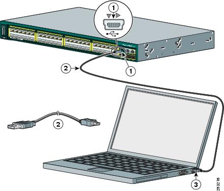
Step 1![]() If you are connecting the switch USB console port to a Windows-based PC for the first time, install the USB driver according to these instructions. See Figure 1-1.
If you are connecting the switch USB console port to a Windows-based PC for the first time, install the USB driver according to these instructions. See Figure 1-1.
- “Installing the Cisco Microsoft Windows XP USB Driver” section
- “Installing the Cisco Microsoft Windows 2000 USB Driver” section
- “Installing the Cisco Microsoft Windows Vista USB Driver” section
Note![]() If you do not want to use the switch USB console port, you can use an RJ-45-to-DB-9 adapter cable to connect the switch RJ-45 console port to a PC or terminal port.
If you do not want to use the switch USB console port, you can use an RJ-45-to-DB-9 adapter cable to connect the switch RJ-45 console port to a PC or terminal port.
Figure 1-1 Connecting the USB Console Cable to the Catalyst 2960-S Switch
|
|
|
|
|
|
|
|
Step 2![]() Start the terminal-emulation program on the PC or the terminal. The program, frequently a PC application such as HyperTerminal or ProcommPlus, makes communication between the switch and your PC or terminal possible.
Start the terminal-emulation program on the PC or the terminal. The program, frequently a PC application such as HyperTerminal or ProcommPlus, makes communication between the switch and your PC or terminal possible.
Step 3![]() Configure the baud rate and character format of the PC or terminal to match the console port default characteristics:
Configure the baud rate and character format of the PC or terminal to match the console port default characteristics:
Step 4![]() Power on the switch as described in the switch getting started guide.
Power on the switch as described in the switch getting started guide.
Step 5![]() The PC or terminal displays the bootloader sequence. Press Enter to display the setup prompt. Follow the steps in the “Completing the Setup Program” section.
The PC or terminal displays the bootloader sequence. Press Enter to display the setup prompt. Follow the steps in the “Completing the Setup Program” section.
Installing the Cisco Microsoft Windows USB Device Driver
A USB device driver must be installed the first time a Microsoft Windows-based PC is connected to the switch USB console port.
Installing the Cisco Microsoft Windows XP USB Driver
Step 1![]() Obtain the file Cisco_usbconsole_driver.zip from the Cisco.com web site and unzip it.
Obtain the file Cisco_usbconsole_driver.zip from the Cisco.com web site and unzip it.
Note![]() You can download the driver file from the Cisco.com site where you download the switch software.
You can download the driver file from the Cisco.com site where you download the switch software.
Step 2![]() If using 32-bit Windows XP, double-click the file setup.exe from the Windows_32 folder. If using 64-bit Windows XP, double-click the file setup(x64).exe from the Windows_64 folder.
If using 32-bit Windows XP, double-click the file setup.exe from the Windows_32 folder. If using 64-bit Windows XP, double-click the file setup(x64).exe from the Windows_64 folder.
Step 3![]() The Cisco Virtual Com InstallShield Wizard begins.
The Cisco Virtual Com InstallShield Wizard begins.
Step 4![]() The Ready to Install the Program window appears, Click Install.
The Ready to Install the Program window appears, Click Install.
Step 5![]() The InstallShield Wizard Completed window appears. Click Finish.
The InstallShield Wizard Completed window appears. Click Finish.
Step 6![]() Connect the USB cable to the PC and switch console port. The LED for the USB console port turns green (see Table 1-10 ), and within a few seconds a series of Found New Hardware Wizard windows appear. Follow the instructions to complete the driver installation.
Connect the USB cable to the PC and switch console port. The LED for the USB console port turns green (see Table 1-10 ), and within a few seconds a series of Found New Hardware Wizard windows appear. Follow the instructions to complete the driver installation.
The USB console is ready for use.
Installing the Cisco Microsoft Windows 2000 USB Driver
Step 1![]() Obtain the file Cisco_usbconsole_driver.zip from the Cisco.com web site and unzip it.
Obtain the file Cisco_usbconsole_driver.zip from the Cisco.com web site and unzip it.
Note![]() You can download the driver file from the Cisco.com site where you download the switch software.
You can download the driver file from the Cisco.com site where you download the switch software.
Step 2![]() Double-click the file setup.exe.
Double-click the file setup.exe.
Step 3![]() The Cisco Virtual Com InstallShield Wizard begins. Click Next.
The Cisco Virtual Com InstallShield Wizard begins. Click Next.
Step 4![]() The Ready to Install the Program window appears, Click Install.
The Ready to Install the Program window appears, Click Install.
Step 5![]() The InstallShield Wizard Completed window appears. Click Finish.
The InstallShield Wizard Completed window appears. Click Finish.
Step 6![]() Connect the USB cable to the PC and switch console port. The LED for the USB console port turns green (see Table 1-10 ), and within a few seconds a series of Found New Hardware Wizard windows appear. Follow the instructions to complete the driver installation.
Connect the USB cable to the PC and switch console port. The LED for the USB console port turns green (see Table 1-10 ), and within a few seconds a series of Found New Hardware Wizard windows appear. Follow the instructions to complete the driver installation.
The USB console is ready for use.
Installing the Cisco Microsoft Windows Vista USB Driver
Step 1![]() Obtain the file Cisco_usbconsole_driver.zip from the Cisco.com web site and unzip it.
Obtain the file Cisco_usbconsole_driver.zip from the Cisco.com web site and unzip it.
Note![]() You can download the driver file from the Cisco.com site where you download the switch software.
You can download the driver file from the Cisco.com site where you download the switch software.
Step 2![]() If using 32-bit Windows Vista, double-click the file setup.exe from the Windows_32 folder. If using 64-bit Windows Vista, double-click the file setup(x64).exe from the Windows_64 folder.
If using 32-bit Windows Vista, double-click the file setup.exe from the Windows_32 folder. If using 64-bit Windows Vista, double-click the file setup(x64).exe from the Windows_64 folder.
Step 3![]() The Cisco Virtual Com InstallShield Wizard begins. Click Next.
The Cisco Virtual Com InstallShield Wizard begins. Click Next.
Step 4![]() The Ready to Install the Program window appears, Click Install.
The Ready to Install the Program window appears, Click Install.
Note![]() If a User Account Control warning appears, click “Allow - I trust this program...” to proceed.
If a User Account Control warning appears, click “Allow - I trust this program...” to proceed.
Step 5![]() The InstallShield Wizard Completed window appears. Click Finish.
The InstallShield Wizard Completed window appears. Click Finish.
Step 6![]() Connect the USB cable to the PC and the switch console port. The LED for the USB console port turns green (see Table 1-10 ), and within a few seconds a series of Found New Hardware Wizard windows appear. Follow the instructions to complete the driver installation.
Connect the USB cable to the PC and the switch console port. The LED for the USB console port turns green (see Table 1-10 ), and within a few seconds a series of Found New Hardware Wizard windows appear. Follow the instructions to complete the driver installation.
The USB console is ready for use.
Uninstalling the Cisco Microsoft Windows USB Driver
Uninstalling the Cisco Microsoft Windows XP and 2000 USB Driver
The driver can be removed using the Windows Add or Remove Programs utility or the setup.exe program.
Using the Add or Remove Programs Utility
Note![]() Disconnect the switch console terminal before uninstalling the driver.
Disconnect the switch console terminal before uninstalling the driver.
Step 1![]() Click Start > Control Panel > Add or Remove Programs.
Click Start > Control Panel > Add or Remove Programs.
Step 2![]() Scroll to Cisco Virtual Com and click Remove.
Scroll to Cisco Virtual Com and click Remove.
Step 3![]() When the Program Maintenance window appears, select the Remove radio button. Click Next.
When the Program Maintenance window appears, select the Remove radio button. Click Next.
Using the Setup.exe Program
Note![]() Disconnect the switch console terminal before uninstalling the driver.
Disconnect the switch console terminal before uninstalling the driver.
Step 1![]() Run setup.exe for Windows 32-bit or setup(x64).exe for Windows-64bit. Click Next.
Run setup.exe for Windows 32-bit or setup(x64).exe for Windows-64bit. Click Next.
Step 2![]() The InstallShield Wizard for Cisco Virtual Com appears. Click Next.
The InstallShield Wizard for Cisco Virtual Com appears. Click Next.
Step 3![]() When the Program Maintenance window appears, select the Remove radio button. Click Next.
When the Program Maintenance window appears, select the Remove radio button. Click Next.
Step 4![]() When the Remove the Program window appears, click Remove.
When the Remove the Program window appears, click Remove.
Step 5![]() When the InstallShield Wizard Completed window appears, click Finish.
When the InstallShield Wizard Completed window appears, click Finish.
Uninstalling the Cisco Microsoft Windows Vista USB Driver
Note![]() Disconnect the switch console terminal before uninstalling the driver.
Disconnect the switch console terminal before uninstalling the driver.
Step 1![]() Run the setup.exe for Windows 32-bit or setup(x64).exe for Windows-64bit. Click Next.
Run the setup.exe for Windows 32-bit or setup(x64).exe for Windows-64bit. Click Next.
Step 2![]() The InstallShield Wizard for Cisco Virtual Com appears. Click Next.
The InstallShield Wizard for Cisco Virtual Com appears. Click Next.
Step 3![]() When the Program Maintenance window appears, select the Remove radio button. Click Next.
When the Program Maintenance window appears, select the Remove radio button. Click Next.
Step 4![]() When the Remove the Program window appears, click Remove.
When the Remove the Program window appears, click Remove.
Step 5![]() If a User Account Control warning appears, click “Allow - I trust this program...” to proceed.
If a User Account Control warning appears, click “Allow - I trust this program...” to proceed.
Step 6![]() When the InstallShield Wizard Completed window appears, click Finish.
When the InstallShield Wizard Completed window appears, click Finish.
Entering the Initial Configuration Information
To set up the switch, you need to complete the setup program, which runs automatically after the switch is powered on. You must assign an IP address and other configuration information necessary for the switch to communicate with the local routers and the Internet. This information is also needed to use the device manager or Cisco Network Assistant to configure and manage the switch.
IP Settings
Obtain this information from your network administrator before you start the setup program:
Completing the Setup Program
If your switches are stacked and there are multiple console connections to individual switches in the stack, the initial setup dialog appears at the console where you first press Enter.
Step 1![]() Enter Yes at these two prompts.
Enter Yes at these two prompts.
Step 2![]() Enter a host name for the switch, and press Return.
Enter a host name for the switch, and press Return.
On a command switch, the host name is limited to 28 characters; on a member switch to 31 characters. Do not use -n, where n is a number, as the last character in a host name for any switch.
Step 3![]() Enter an enable secret password, and press Return.
Enter an enable secret password, and press Return.
The password can be from 1 to 25 alphanumeric characters, can start with a number, is case sensitive, allows spaces, but ignores leading spaces. The secret password is encrypted, and the enable password is in plain text.
Step 4![]() Enter an enable password, and press Return.
Enter an enable password, and press Return.
Step 5![]() Enter a virtual terminal (Telnet) password, and press Return.
Enter a virtual terminal (Telnet) password, and press Return.
The password can be from 1 to 25 alphanumeric characters, is case sensitive, allows spaces, but ignores leading spaces.
Step 6![]() (Optional) Configure Simple Network Management Protocol (SNMP) by responding to the prompts. You can also configure SNMP later through the CLI, the device manager, or the Network Assistant application. To configure SNMP later, enter no.
(Optional) Configure Simple Network Management Protocol (SNMP) by responding to the prompts. You can also configure SNMP later through the CLI, the device manager, or the Network Assistant application. To configure SNMP later, enter no.
Step 7![]() Enter the interface name (physical interface or VLAN name) of the connection to the management network, and press Return. For this release, always use vlan1 as that interface.
Enter the interface name (physical interface or VLAN name) of the connection to the management network, and press Return. For this release, always use vlan1 as that interface.
Step 8![]() Configure the interface by entering the switch IP address and subnet mask and pressing Return. The IP address and subnet masks shown are examples.
Configure the interface by entering the switch IP address and subnet mask and pressing Return. The IP address and subnet masks shown are examples.
Step 9![]() Enter Y to configure the switch as the cluster command switch. Enter N to configure it as a member switch or as a standalone switch.
Enter Y to configure the switch as the cluster command switch. Enter N to configure it as a member switch or as a standalone switch.
If you enter N, the switch appears as a candidate switch in the Network Assistant GUI. You can configure the switch as a command switch later through the CLI, the device manager, or the Network Assistant application. To configure it later, enter no.
You have now completed the initial configuration of the switch and the switch. This is an example of the configuration output that appears:
Make your selection, and press Return.
The switch now runs this default configuration. If you want to change this configuration or perform other management tasks, see the “Management Options” section.
Configuring the Switch with the CLI-Based Setup Program
This appendix provides a CLI-based setup procedure for a Catalyst 2960-S standalone switch or a switch stack. Before you turn on the switch power, review the safety warnings in Chapter1, “Switch Installation”
Accessing the CLI Through Express Setup
You can access the CLI on an unconfigured switch. Set the switch in Express Setup mode and connect a switch Ethernet port to an Ethernet port on your PC or workstation. Follow the steps described in the getting started guide for turning on the switch and using Express Setup.
When the switch is in Express Setup mode, open a Telnet session to the switch by entering the IP address 10.0.0.1. Enter the setup user EXEC command. Enter the information described in the “IP Settings” section and the “Completing the Setup Program” section.
After you have entered the configuration information for the switch, save it to flash memory by using the write memory privileged EXEC command.
Note
In Express Setup mode, the IP address 10.0.0.1 remains active on the switch until you enter the write memory command. You lose the Telnet connection after entering the write memory command.
For information about using the CLI, see the switch command reference for this release.
Accessing the CLI Through the Console Port
You can access the CLI on a configured or unconfigured switch by connecting the RJ-45 console port or USB console port of the switch to your PC or workstation and accessing the switch through a terminal emulation program.
Note
Connecting the RJ-45 Console Port or USB Console Port
Step 1
- “Installing the Cisco Microsoft Windows XP USB Driver” section
- “Installing the Cisco Microsoft Windows 2000 USB Driver” section
- “Installing the Cisco Microsoft Windows Vista USB Driver” section
Note
Figure 1-1 Connecting the USB Console Cable to the Catalyst 2960-S Switch
Step 2
Step 3
Step 4
Step 5
Installing the Cisco Microsoft Windows USB Device Driver
A USB device driver must be installed the first time a Microsoft Windows-based PC is connected to the switch USB console port.
Installing the Cisco Microsoft Windows XP USB Driver
Step 1
Note
Step 2
Step 3
Step 4
Step 5
Step 6
The USB console is ready for use.
Installing the Cisco Microsoft Windows 2000 USB Driver
Step 1
Note
Step 2
Step 3
Step 4
Step 5
Step 6
The USB console is ready for use.
Installing the Cisco Microsoft Windows Vista USB Driver
Step 1
Note
Step 2
Step 3
Step 4
Note
Step 5
Step 6
The USB console is ready for use.
Uninstalling the Cisco Microsoft Windows XP and 2000 USB Driver
The driver can be removed using the Windows Add or Remove Programs utility or the setup.exe program.
Using the Add or Remove Programs Utility
Note
Step 1
Step 2
Step 3
Using the Setup.exe Program
Note
Step 1
Step 2
Step 3
Step 4
Step 5
Uninstalling the Cisco Microsoft Windows Vista USB Driver
Note
Step 1
Step 2
Step 3
Step 4
Step 5
Step 6
Entering the Initial Configuration Information
To set up the switch, you need to complete the setup program, which runs automatically after the switch is powered on. You must assign an IP address and other configuration information necessary for the switch to communicate with the local routers and the Internet. This information is also needed to use the device manager or Cisco Network Assistant to configure and manage the switch.
IP Settings
Obtain this information from your network administrator before you start the setup program:
Completing the Setup Program
If your switches are stacked and there are multiple console connections to individual switches in the stack, the initial setup dialog appears at the console where you first press Enter.
Step 1
Step 2
On a command switch, the host name is limited to 28 characters; on a member switch to 31 characters. Do not use -n, where n is a number, as the last character in a host name for any switch.
Step 3
The password can be from 1 to 25 alphanumeric characters, can start with a number, is case sensitive, allows spaces, but ignores leading spaces. The secret password is encrypted, and the enable password is in plain text.
Step 4
Step 5
The password can be from 1 to 25 alphanumeric characters, is case sensitive, allows spaces, but ignores leading spaces.
Step 6
Step 7
Step 8
Step 9
If you enter N, the switch appears as a candidate switch in the Network Assistant GUI. You can configure the switch as a command switch later through the CLI, the device manager, or the Network Assistant application. To configure it later, enter no.
You have now completed the initial configuration of the switch and the switch. This is an example of the configuration output that appears:
Make your selection, and press Return.
The switch now runs this default configuration. If you want to change this configuration or perform other management tasks, see the “Management Options” section.
 Feedback