Catalyst 3650 Switch Hardware Installation Guide
Bias-Free Language
The documentation set for this product strives to use bias-free language. For the purposes of this documentation set, bias-free is defined as language that does not imply discrimination based on age, disability, gender, racial identity, ethnic identity, sexual orientation, socioeconomic status, and intersectionality. Exceptions may be present in the documentation due to language that is hardcoded in the user interfaces of the product software, language used based on RFP documentation, or language that is used by a referenced third-party product. Learn more about how Cisco is using Inclusive Language.
- Updated:
- May 16, 2016
Chapter: Switch Installation
Switch Installation
This chapter describes how to install and connect a Catalyst 3650 switch. It also includes planning and cabling considerations for stacking switches.
Read the topics and perform the procedures in this order:
2.![]() Planning a Switch Data Stack
Planning a Switch Data Stack
4.![]() Installing the StackWise Ports
Installing the StackWise Ports
5.![]() Installing and Removing an SFP and SFP+ Module
Installing and Removing an SFP and SFP+ Module
6.![]() Connecting a Device to an Ethernet Port
Connecting a Device to an Ethernet Port
For initial switch setup, how to assign the switch IP address, and for powering information, see the switch getting started guide on Cisco.com.
Preparing for Installation
Ensure that the following sections are read and understood carefully before the switch is installed.
Safety Warnings
This section includes the basic installation caution and warning statements. Translations of the warning statements appear in the Regulatory Compliance and Safety Information for the Catalyst 3650 Switch at http://www.cisco.com/c/en/us/td/docs/switches/lan/catalyst3650/hardware/regulatory/compliance/cat3650_rcsi.html. Read this section before you start the installation procedure.

Warning![]() Before working on equipment that is connected to power lines, remove jewelry (including rings, necklaces, and watches). Metal objects will heat up when connected to power and ground and can cause serious burns or weld the metal object to the terminals. Statement 43
Before working on equipment that is connected to power lines, remove jewelry (including rings, necklaces, and watches). Metal objects will heat up when connected to power and ground and can cause serious burns or weld the metal object to the terminals. Statement 43
Warning![]() Do not stack the chassis on any other equipment. If the chassis falls, it can cause severe bodily injury and equipment damage. Statement 48
Do not stack the chassis on any other equipment. If the chassis falls, it can cause severe bodily injury and equipment damage. Statement 48
Warning![]() Ethernet cables must be shielded when used in a central office environment. Statement 171
Ethernet cables must be shielded when used in a central office environment. Statement 171
Warning![]() Voice over IP (VoIP) service and the emergency calling service do not function if power fails or is disrupted. After power is restored, you might have to reset or reconfigure equipment to regain access to VoIP and the emergency calling service. In the USA, this emergency number is 911. You need to be aware of the emergency number in your country. Statement 361
Voice over IP (VoIP) service and the emergency calling service do not function if power fails or is disrupted. After power is restored, you might have to reset or reconfigure equipment to regain access to VoIP and the emergency calling service. In the USA, this emergency number is 911. You need to be aware of the emergency number in your country. Statement 361
Warning![]() Attach only the following Cisco external power system to the switch: PWR-RPS2300. Statement 387
Attach only the following Cisco external power system to the switch: PWR-RPS2300. Statement 387
Warning![]() Do not work on the system or connect or disconnect cables during periods of lightning activity. Statement 1001
Do not work on the system or connect or disconnect cables during periods of lightning activity. Statement 1001
Warning![]() Read the installation instructions before connecting the system to the power source. Statement 1004
Read the installation instructions before connecting the system to the power source. Statement 1004
Warning![]() This unit is intended for installation in restricted access areas. A restricted access area can be accessed only through the use of a special tool, lock and key, or other means of security. Statement 1017
This unit is intended for installation in restricted access areas. A restricted access area can be accessed only through the use of a special tool, lock and key, or other means of security. Statement 1017
Warning![]() The plug-socket combination must be accessible at all times, because it serves as the main disconnecting device. Statement 1019
The plug-socket combination must be accessible at all times, because it serves as the main disconnecting device. Statement 1019
Warning![]() Use copper conductors only. Statement 1025
Use copper conductors only. Statement 1025
Warning![]() This unit might have more than one power supply connection. All connections must be removed to de-energize the unit. Statement 1028
This unit might have more than one power supply connection. All connections must be removed to de-energize the unit. Statement 1028
Warning![]() Only trained and qualified personnel should be allowed to install, replace, or service this equipment. Statement 1030
Only trained and qualified personnel should be allowed to install, replace, or service this equipment. Statement 1030
Warning![]() Ultimate disposal of this product should be handled according to all national laws and regulations. Statement 1040
Ultimate disposal of this product should be handled according to all national laws and regulations. Statement 1040
Warning![]() For connections outside the building where the equipment is installed, the following ports must be connected through an approved network termination unit with integral circuit protection: 10/100/1000 Ethernet. Statement 1044
For connections outside the building where the equipment is installed, the following ports must be connected through an approved network termination unit with integral circuit protection: 10/100/1000 Ethernet. Statement 1044
Warning![]() To prevent the system from overheating, do not operate it in an area that exceeds the maximum recommended ambient temperature of:
To prevent the system from overheating, do not operate it in an area that exceeds the maximum recommended ambient temperature of:
113°F (45°C) Statement 1047
Warning![]() No user-serviceable parts inside. Do not open. Statement 1073
No user-serviceable parts inside. Do not open. Statement 1073
Warning![]() Installation of the equipment must comply with local and national electrical codes. Statement 1074
Installation of the equipment must comply with local and national electrical codes. Statement 1074
Warning![]() To prevent airflow restriction, allow clearance around the ventilation openings to be at least:
To prevent airflow restriction, allow clearance around the ventilation openings to be at least:
3 in. (7.6 cm) Statement 1076


Note![]() The grounding architecture of this product is DC-isolated (DC-I).
The grounding architecture of this product is DC-isolated (DC-I).
Installation Guidelines
Before installing the switch, verify that these guidelines are met.
–![]() Front-panel indicators can be easily read.
Front-panel indicators can be easily read.
–![]() Clearance is at least 4.4 in. (11.1 cm) from the switch’s rear panel.
Clearance is at least 4.4 in. (11.1 cm) from the switch’s rear panel.
–![]() Access to ports is sufficient for unrestricted cabling.
Access to ports is sufficient for unrestricted cabling.
–![]() AC power cord can reach from the AC power outlet to the connector on the switch’s rear panel.
AC power cord can reach from the AC power outlet to the connector on the switch’s rear panel.
–![]() The SFP or SFP+ module minimum bend radius and connector length are met. See the corresponding SFP or SFP+ module documentation for more information.
The SFP or SFP+ module minimum bend radius and connector length are met. See the corresponding SFP or SFP+ module documentation for more information.
–![]() Access to the rear of the rack is sufficient for connecting the optional Cisco RPS 2300 module.
Access to the rear of the rack is sufficient for connecting the optional Cisco RPS 2300 module.
- For switches with the optional 1025-W power supply module (PWR-C2-1025WAC) or the 1100-W power supply module (PWR-C1-1100WAC), rack-mount the switch before installing the power supply module.
- Ensure that the power supply modules and fan modules are securely inserted in the chassis before moving the switch.
- When connecting or disconnecting the power cord on a switch that is installed above or below a 1025 W or 1100 W power supply-equipped switch, you might have to remove the module from the switch to access the power cord.
- Cabling is away from sources of electrical noise, such as radios, power lines, and fluorescent lighting fixtures. Make sure that cabling is safely away from other devices that might damage the cables.
- For copper connections on Ethernet ports, cable lengths from the switch to connected devices can be up to 328 feet (100 meters).
- Each port must match the wave-length specifications on the other end of the cable, and the cable must not exceed the maximum cable length.
- Operating environment is within the correct ranges.
- Airflow around the switch and through the vents is unrestricted.
- Temperature around the unit does not exceed 113°F (45°C). If the switch is installed in a closed or multirack assembly, the temperature around it might be greater than normal room temperature.
- Cisco Ethernet switches are equipped with cooling mechanisms, such as fans and blowers. However, these fans and blowers can draw dust and other particles, causing contaminant build-up inside the chassis, which can result in system malfunction. You must install this equipment in an environment that is as free from dust and foreign conductive material (such as metal flakes from construction activities), as is possible.
- The following standards provide guidelines for acceptable working environments and acceptable levels of suspended particulate matter:
–![]() Network Equipment Building Systems (NEBS) GR-63-CORE (only with the DC power supply)
Network Equipment Building Systems (NEBS) GR-63-CORE (only with the DC power supply)
–![]() National Electrical Manufacturers Association (NEMA) Type 1
National Electrical Manufacturers Association (NEMA) Type 1
Tools and Equipment
Verifying Switch Operation
Before you install the switch in a rack, or on a table or shelf, you should power on the switch and verify that the switch passes POST. For the steps that should be performed to connect a PC to the switch and to run the Express Setup, see the “Running Express Setup” section in the Catalyst 3650 Switch Getting Started Guide at http://www.cisco.com/c/en/us/td/docs/switches/lan/catalyst3650/hardware/quick/guide/cat3650_gsg.html.
Note![]() When you connect the RPS to the switch, put the RPS in standby mode. Set the RPS to active mode during normal operation.
When you connect the RPS to the switch, put the RPS in standby mode. Set the RPS to active mode during normal operation.
Warning![]() Attach only the following Cisco external power system to the switch: PWR-RPS2300. Statement 387
Attach only the following Cisco external power system to the switch: PWR-RPS2300. Statement 387
Powering Off the Switch
After a successful POST, disconnect the power cord from the switch. Install the switch in a rack, on a table, or on a shelf, as described in “Installing the Switch,” section.
Planning a Switch Data Stack
Catalyst 3650 switches can share bandwidth by using data stacking.
Switch Stacking Guidelines
For general concepts and management procedures for switch stacks, see the Cisco Catalyst 3650 Series Switches Software Configuration Guides at http://www.cisco.com/c/en/us/support/switches/catalyst-3650-series-switches/products-installation-and-configuration-guides-list.html.
A StackWise adapter must be installed in the stacking port to enable stacking. The StackWise cable connects to the StackWise adapter in the stacking port. For switches ordered with stacking, the StackWise adapters are preinstalled. If the switch is not ordered with stacking, the adapters must be ordered separately and installed.
Before connecting the switches in a stack, observe these stacking guidelines:
- Size of the switch and any optional power supply module. The 1025-W and 1100-W power supply modules are longer than the other modules. Stacking switches with the same power supply modules makes it easier to cable the switches.
- Length of the StackWise cable. Depending on the configurations that you have, you might need different-sized StackWise cables. If you do not specify the length of the StackWise cable, the 0.5-meter cable is supplied. If you need the 1-meter cable or the 3-meter cable, you can order it from your Cisco supplier. The “Data Stack Cabling Configurations” section provides examples of recommended configurations.
- Minimum bend radius and coiled diameter for StackWise cables. We recommend a minimum bend radius and coiled diameter for each StackWise cable.
- Data stacks can be created with up to nine switches in a stack.
Note![]() You cannot have a switch stack containing a mix of Catalyst 3650 and Catalyst 3850 switches.
You cannot have a switch stack containing a mix of Catalyst 3650 and Catalyst 3850 switches.
Data Stack Cabling Configurations
Figure 2-1 is an example of a recommended configuration that uses the supplied 0.5-meter StackWise cable. In this example, the switches are stacked in a vertical rack or on a table. This configuration provides redundant connections.
The configuration example (Figure 2-1) uses the supplied 0.5-meter StackWise cable. The example shows the full-ring configuration that provides redundant connections.
Figure 2-1 Data Stacking the Catalyst 3650 Switches in a Rack or on a Table Using the 0.5-meter StackWise Cables
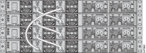
Figure 2-2 shows a recommended configuration when the switches are mounted side-by-side. Use the 1-meter and the 3-meter StackWise cables to connect the switches. This configuration provides redundant connections.
Figure 2-2 Data Stacking up to Four Switches in a Side-by-Side Mounting

Data Stack Bandwidth and Partitioning Examples
This section provides examples of data stack bandwidth and possible data stack partitioning.
Figure 2-3 shows a data stack of Catalyst 3650 switches that provides full bandwidth and redundant StackWise cable connections.
Figure 2-3 Example of a Data Stack with Full Bandwidth Connections
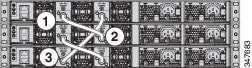
Figure 2-4 shows an example of a stack of Catalyst 3650 switches with incomplete StackWise cabling connections. This stack provides only half bandwidth and does not have redundant connections.
Figure 2-4 Example of a Data Stack with Half Bandwidth Connections
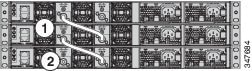
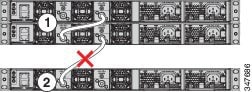
Figure 2-5 and Figure 2-6 show data stacks of Catalyst 3650 switches with failover conditions. In Figure 2-5, the StackWise cable is bad in link 2. Therefore, this stack provides only half bandwidth and does not have redundant connections. In Figure 2-6, link 2 is bad. Therefore, this stack partitions into two stacks, and the top and bottom switches become the active switches in the stack. If the bottom switch is a member (not the active or standby switch), it reloads.
Figure 2-5 Example of a Data Stack with a Failover Condition
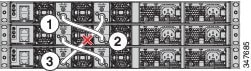
Figure 2-6 Example of a Partitioned Data Stack with a Failover Condition
Power-On Sequence for Switch Data Stacks
Consider these guidelines before you power on the switches in a stack:
- The sequence in which the switches are first powered on might affect the choice of switch that becomes the active switch and the standby switch.
- There are two ways to elect an active switch:
–![]() If you want a particular switch to become the active switch, configure it with the highest priority. Among switches with same priority, the switch with the lowest MAC address becomes the active switch.
If you want a particular switch to become the active switch, configure it with the highest priority. Among switches with same priority, the switch with the lowest MAC address becomes the active switch.
–![]() If you want a particular switch to become the active switch, power on that switch first. This switch remains the active switch until a re-election is required. After 2 minutes, power on the other switches in the stack. If you have no preference as to which switch becomes the active switch, power on all the switches in the stack within 1 minute. These switches participate in the active switch election. Switches powered on after 2 minutes do not participate in the election.
If you want a particular switch to become the active switch, power on that switch first. This switch remains the active switch until a re-election is required. After 2 minutes, power on the other switches in the stack. If you have no preference as to which switch becomes the active switch, power on all the switches in the stack within 1 minute. These switches participate in the active switch election. Switches powered on after 2 minutes do not participate in the election.
If changes are made to the stack without powering down the switches, the following results might occur:
- If two operating partial-ring stacks are connected together using a stack cable, a stack merge might occur. This situation reloads the whole stack (all the switches in the stack).
- If some switches in the stack are completely separated from the stack, a stack split might occur.
- A stack split might occur on a full-ring stack if:
–![]() More than one running switch is removed without powering down.
More than one running switch is removed without powering down.
–![]() More than one stack cable is removed without powering down.
More than one stack cable is removed without powering down.
–![]() A switch is removed without powering down.
A switch is removed without powering down.
–![]() A stack cable is removed without powering down.
A stack cable is removed without powering down.
- In a split stack, depending on where the active and standby switches are located, either two stacks might be formed (with the standby taking over as the new active switch in the newly formed stack), or all the members in the newly formed stack might reload.
Note![]() These results depend on how the switches are connected. You can remove two or more switches from the stack without splitting the stack.
These results depend on how the switches are connected. You can remove two or more switches from the stack without splitting the stack.
For conditions that may cause a stack re-election or to manually elect the active switch, see the switch’s software configuration guide at:
Changes to Switch Stack Membership
If you replace a stack member with an identical model, the new switch functions with exactly the same configuration as the replaced switch, assuming that the new switch (referred to as the provisioned switch) is using the same member number as the replaced switch.
The operation of the switch stack continues uninterrupted during membership changes unless you remove the active switch or you add powered-on standalone switches or switch stacks.
Note![]() A switch stack always has one active switch and one standby switch. The active switch contains the saved and running configuration files for the switch stack. If the active switch becomes unavailable, the standby switch assumes the role of the active switch, and continues to the keep the stack operational.
A switch stack always has one active switch and one standby switch. The active switch contains the saved and running configuration files for the switch stack. If the active switch becomes unavailable, the standby switch assumes the role of the active switch, and continues to the keep the stack operational.
- Adding powered-on switches (merging) causes all the switches to reload and elect a new active switch from among themselves. The newly elected active switch retains its role and configuration. All the other switches change their stack member numbers to the lowest available numbers and use the stack configuration of the newly elected active switch.
- Removing powered-on stack members causes the switch stack to divide (partition) into two or more switch stacks, each with the same configuration. This can cause an IP address configuration conflict in your network. If you want the switch stacks to remain separate, change the IP address or addresses of the newly created switch stacks.
If a newly created switch stack does not have an active switch or standby switch, the switch stack will reload and elect a new active switch.
Note![]() Make sure that you power off the switches that you add to or remove from the switch stack.
Make sure that you power off the switches that you add to or remove from the switch stack.
After adding or removing stack members, make sure that the switch stack is operating at full bandwidth. Press the Mode button on a stack member until the Stack mode LED is on. The last two right port LEDs on all the switches in the stack should be green. Depending on the switch model, the last two right ports are 10-Gigabit Ethernet ports or small form-factor pluggable (SFP) module ports (10/100/1000 ports). If one or both of these LEDs are not green on any of the switches, the stack is not operating at full bandwidth.
If you remove the powered-on members but do not want to partition the stack:
Installing the Switch
The illustrations shown in this section show the Catalyst 3650-48 PoE+ switch as an example. You can install other Catalyst 3650 switches following the same procedures.
Rack-Mounting a Switch
To install the switch in a 19-inch rack, follow the instructions described in this section.
The 19-inch brackets are included with the switch. Installing the switch in other rack types requires an optional bracket kit that is not included with the switch. Figure 2-7 shows the mounting brackets and part numbers.
Figure 2-7 Rack-Mounting Brackets

|
|
|
||
|
|
Extension rails and brackets for four-point mounting, includes 19-inch brackets. (4PT-KIT-T1=) |
|
|
|
|
|
Attaching the Rack-Mount Brackets
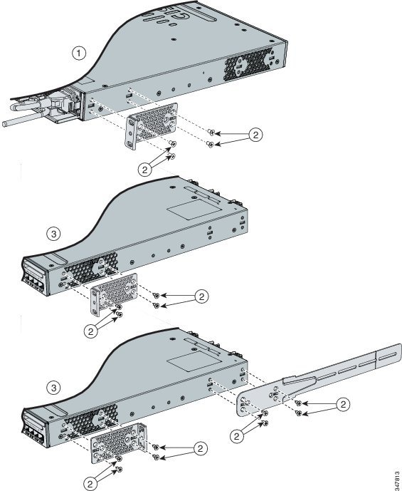
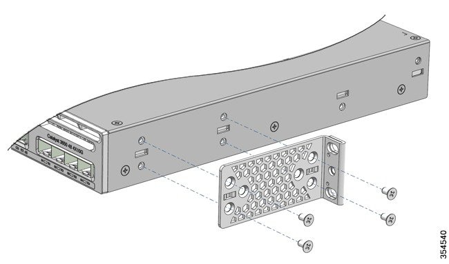
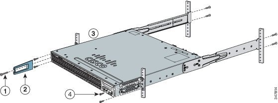
To install the switch in a rack, use four No. 8 Phillips flat-head screws to attach the long side of the brackets to the switch for the front-mounting or rear-mounting positions (Figure 2-8). Use four screws to attach the brackets for the front-mounting position.
Figure 2-8 Attaching Brackets for 19-inch Racks
|
|
|
|
|
|
|
|
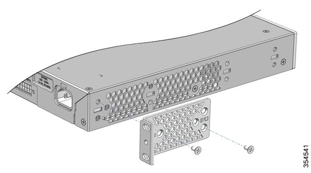
Figure 2-9 Attaching Brackets for Catalyst 3650-24PDM and Catalyst 3650-48FQM Switches
Mounting the Switch in a Rack
After the brackets are attached to the switch, use the supplied Phillips machine screws to attach the brackets to the rack (Figure 2-10). Use the black Phillips machine screw to attach the cable guide to the left or right bracket.
Figure 2-10 Mounting the Switch on a Rack
|
|
|
||
|
|
|
After you complete the switch installation, see the “After Installing the Switch” section for more information about switch configuration.
Table-Mounting or Shelf-Mounting
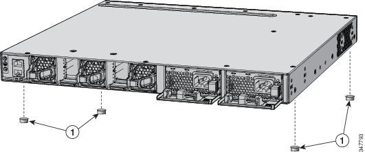
To install the switch on a table or shelf, locate the adhesive strip with the rubber feet in the mounting-kit envelope. Attach the four rubber feet to the recessed areas at the bottom of the chassis (see Figure 2-11).
Figure 2-11 Attaching the Adhesive Pads for Table-Mounting or Shelf-Mounting
|
|
After you complete the switch installation, see the “After Installing the Switch” section for more information about the switch configuration.
After Installing the Switch
After the switch is installed, you can configure the switch using various options.
- Configure the switch by running the Express Setup to enter the initial switch configuration. For instructions, see the Catalyst 3650 Switch Getting Started Guide at http://www.cisco.com/c/en/us/td/docs/switches/lan/catalyst3650/hardware/quick/guide/cat3650_gsg.html.
- Use the CLI setup program to enter the initial switch configuration.
- Connect to the front-panel ports. See the “Connecting a Device to an Ethernet Port” section.
Installing the StackWise Ports
Before connecting the StackWise cables, review the “Planning a Switch Data Stack” section. Always use a Cisco-approved StackWise cable to connect the switches.
Step 1![]() Remove the dust covers from the StackWise cables and store them for future use.
Remove the dust covers from the StackWise cables and store them for future use.
A StackWise adapter must be installed in the StackWise port to enable stacking. In the default setup, the StackWise adapter blanks are installed in the StackWise ports. If StackWise stacking is ordered with the switch, StackWise adapters are already installed in the StackWise ports, and you can proceed to step 4![]() .
.
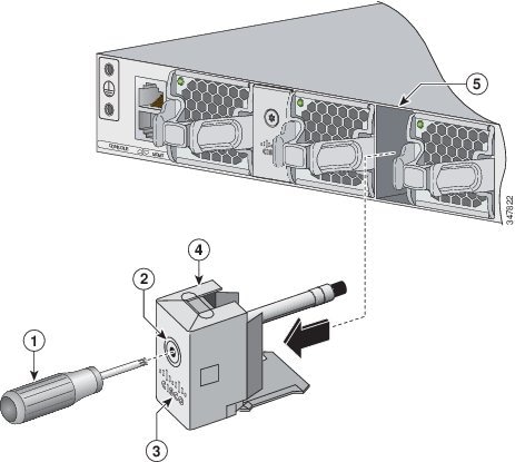
Step 2![]() Remove the StackWise adapter blanks from each destination StackWise port using the Torx T15 Allen key provided in the stacking kit (or a Torx T15 screwdriver), as shown in Figure 2-12. Store them for future use.
Remove the StackWise adapter blanks from each destination StackWise port using the Torx T15 Allen key provided in the stacking kit (or a Torx T15 screwdriver), as shown in Figure 2-12. Store them for future use.
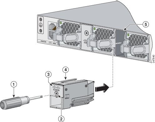
Step 3![]() Install a StackWise adapter in each destination StackWise port, and secure it in place using the supplied Torx T15 key, or a Torx T15 screwdriver, as shown in Figure 2-13.
Install a StackWise adapter in each destination StackWise port, and secure it in place using the supplied Torx T15 key, or a Torx T15 screwdriver, as shown in Figure 2-13.
Note![]() It is not necessary to remove the fan modules before the removal or installation of the StackWise adapter. If the installation is performed with the system powered on, the fans must be left in the installed position at all times.
It is not necessary to remove the fan modules before the removal or installation of the StackWise adapter. If the installation is performed with the system powered on, the fans must be left in the installed position at all times.
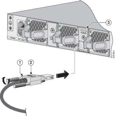
Step 4![]() Connect the StackWise cable to the StackWise port on the switch’s rear panel:
Connect the StackWise cable to the StackWise port on the switch’s rear panel:
a.![]() Align the StackWise cable connector with the StackWise adapter in the StackWise port.
Align the StackWise cable connector with the StackWise adapter in the StackWise port.
b.![]() Insert the StackWise cable connector into the StackWise port, as shown in Figure 2-14. Make sure that the Cisco logo is on the top side of the connector.
Insert the StackWise cable connector into the StackWise port, as shown in Figure 2-14. Make sure that the Cisco logo is on the top side of the connector.
c.![]() Finger-tighten the screws (clockwise direction).
Finger-tighten the screws (clockwise direction).
Step 5![]() Connect the other end of the cable to the port on the other switch and finger-tighten the screws. Do not overtighten the screws.
Connect the other end of the cable to the port on the other switch and finger-tighten the screws. Do not overtighten the screws.
Figure 2-12 Removing the StackWise Adapter Blank from a StackWise Port
|
|
|
||
|
|
|
||
|
|
|
Figure 2-13 Installing the StackWise Adapter in a StackWise Port
|
|
|||
|
|
|
||
|
|
|
Figure 2-14 Connecting the StackWise Cable to the StackWise Adapter
|
|
|
||
|
|
|
Note ●![]() When you have to remove the StackWise cable from the connector, make sure that you fully unscrew the correct screws. When the connectors are not being used, replace the dust covers.
When you have to remove the StackWise cable from the connector, make sure that you fully unscrew the correct screws. When the connectors are not being used, replace the dust covers.
- If the StackWise cable is difficult to remove, you can use a flat-blade screwdriver to assist with removing the cable screws. The screwdriver only works for cable removal and is designed to slip off if used for cable installation.
Installing and Removing an SFP and SFP+ Module
This section explains how to install and remove SFP and SFP+ modules.
Installing an SFP and SFP+ Module
Warning![]() Class 1 laser product. Statement 1008
Class 1 laser product. Statement 1008
Note ●![]() Do not remove the dust plugs from the SFP modules or the rubber caps from the fiber-optic cable until you are ready to connect the cable. The plugs and caps protect the module ports and cables from contamination and ambient light.
Do not remove the dust plugs from the SFP modules or the rubber caps from the fiber-optic cable until you are ready to connect the cable. The plugs and caps protect the module ports and cables from contamination and ambient light.
- Removing and installing an SFP module can shorten its useful life. Do not remove and insert any SFP module more often than is necessary.
- To prevent ESD damage, follow your normal board and component handling procedures when connecting cables to the switch and other devices.
- Use only supported SFP modules on the switch.
- When you insert several SFPs in multiple switch ports, wait for 5 seconds between inserting each SFP. This will prevent the ports from going into error disabled mode. Similarly, when you remove an SFP from a port, wait for 5 seconds before reinserting it.
To install an SFP or SFP+ module, follow the procedures given below:
Step 1![]() Attach an ESD-preventive wrist strap to your wrist and to an earth-ground surface.
Attach an ESD-preventive wrist strap to your wrist and to an earth-ground surface.
Step 2![]() Find the send (TX) and receive (RX) markings that identify the top of the SFP module.
Find the send (TX) and receive (RX) markings that identify the top of the SFP module.
On some SFP modules, the send and receive (TX and RX) markings might be indicated by arrows that show the direction of the connection.
Step 3![]() If the SFP module has a bale-clasp latch, move it to the open, unlocked position.
If the SFP module has a bale-clasp latch, move it to the open, unlocked position.
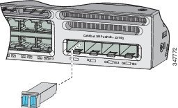
Step 4![]() Align the module in front of the slot opening, and push until you feel the connector snap into place.
Align the module in front of the slot opening, and push until you feel the connector snap into place.
Figure 2-15 Aligning the Module in Front of the Slot Opening
Step 5![]() If the module has a bale-clasp latch, close it to lock the SFP module in place.
If the module has a bale-clasp latch, close it to lock the SFP module in place.
Step 6![]() Remove the SFP dust plugs.
Remove the SFP dust plugs.
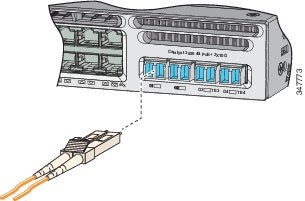
Step 7![]() Connect the SFP cables.
Connect the SFP cables.
Figure 2-16 Connecting an SFP Cable to an SFP Module Installed in an Uplink Port
Removing an SFP or SFP+ Module
To remove an SFP or SFP+ module, follow the procedures given below:
Step 1![]() Attach an ESD-preventive wrist strap to your wrist and to an earth ground surface.
Attach an ESD-preventive wrist strap to your wrist and to an earth ground surface.
Step 2![]() Disconnect the cable from the SFP module. For reattachment, note which cable connector plug is send (TX) and which is receive (RX).
Disconnect the cable from the SFP module. For reattachment, note which cable connector plug is send (TX) and which is receive (RX).
Step 3![]() Insert a dust plug into the optical ports of the SFP module to keep the optical interfaces clean.
Insert a dust plug into the optical ports of the SFP module to keep the optical interfaces clean.
Step 4![]() If the module has a bale-clasp latch, pull the bale out and down to eject the module. If you cannot use your finger to open the latch, use a small, flat-blade screwdriver or other long, narrow instrument to open it.
If the module has a bale-clasp latch, pull the bale out and down to eject the module. If you cannot use your finger to open the latch, use a small, flat-blade screwdriver or other long, narrow instrument to open it.
Step 5![]() Grasp the SFP module, and carefully remove it from the slot.
Grasp the SFP module, and carefully remove it from the slot.
Step 6![]() Place the SFP module in an antistatic bag or other protective environment.
Place the SFP module in an antistatic bag or other protective environment.
Connecting a Device to an Ethernet Port
10/100/1000 Ethernet Port Connections
The 10/100/1000 Ethernet ports use RJ-45 connectors with Ethernet pinouts. The maximum cable length is 328 feet (100 meters). The 100BASE-TX and 1000BASE-T traffic requires a Category 5, Category 5e, or Category 6 UTP cable. The 10BASE-T traffic can use a Category 3 or Category 4 cable.
The autonegotiation feature is enabled by default on the switch. In this setting, the switch ports configure themselves to operate at the speed of the attached device. If the attached device does not support autonegotiation, you can explicitly set the switch port speed and duplex parameters. To maximize performance, either let the ports autonegotiate both speed and duplex, or set the port speed and duplex parameters on both ends of the connection.
For simplified cabling, the automatic medium-dependent interface crossover (auto-MDIX) feature is enabled by default on the switch. With auto-MDIX enabled, the switch detects the required cable type for copper Ethernet connections and configures the interface accordingly. Therefore, you can use either a crossover or a straight-through cable for connections to a 10/100/1000 Ethernet port regardless of the type of device at the other end of the connection.
See the switch’s software configuration guide or the switch command reference document on Cisco.com for more information about enabling or disabling autonegotiation and auto-MDIX.
If auto-MDIX is disabled, use the guidelines in Table 2-1 to select the correct cable for connecting the switch 10/100/1000 Ethernet ports to other devices.
|
|
|
|
|---|---|---|
|
1.100BASE-TX and 1000BASE-T traffic requires a twisted four-pair, Category 5, Category 5e, or Category 6 cable. 10BASE-T traffic can use a Category 3 or Category 4 cable. |
100M/1G/2.5G/5G/10G Ethernet Port Connections
The 100M/1G/2.5G/5G/10G Ethernet ports use RJ45 connectors with Ethernet pinouts. These ports do not support 10 Mbps speed. The 100 Mbps and 1 Gbps traffic require a Category 5/5e/6 unshielded twisted pair (UTP) cable at a maximum cable length of 100 m. The 2.5 Gbps traffic requires a Category 5e/6/6a UTP cable at a maximum cable length of 100 m. The 5 Gbps traffic requires a Category 5e UTP cable at a maximum cable length of 70 m and a Category 6/6a UTP cable at a maximum cable length of 100 m. The 10 Gbps traffic requires a Category 6 UTP cable at maximum cable length of 55 m and a Category 6a UTP cable at maximum cable length of 100 m.
PoE+ Port and Cisco UPOE Connections
The 10/100/1000 PoE+ and Cisco UPOE ports have the same autonegotiation settings and cabling requirements that are described in the “10/100/1000 Ethernet Port Connections” section. These ports can provide PoE or PoE+ inline power.
PoE inline power supports devices compliant with the IEEE 802.3af standard, as well as prestandard Cisco IP phones and Cisco Aironet Access Points. Each port can deliver up to 15.4 W of PoE.
PoE+ inline power supports devices that are compliant with the IEEE 802.3at standard, by delivering up to 30 W of PoE+ power per port to all the switch ports.
Cisco UPOE ports provide up to 60 W power per port for connected devices.
Note![]() Many legacy-powered devices, including older Cisco IP phones and access points that do not fully support IEEE 802.3af, might not support PoE when connected to the switches by a crossover cable.
Many legacy-powered devices, including older Cisco IP phones and access points that do not fully support IEEE 802.3af, might not support PoE when connected to the switches by a crossover cable.
Warning![]() Voice over IP (VoIP) service and the emergency calling service do not function if power fails or is disrupted. After power is restored, you might have to reset or reconfigure equipment to regain access to VoIP and the emergency calling service. In the USA, this emergency number is 911. You need to be aware of the emergency number in your country. Statement 361
Voice over IP (VoIP) service and the emergency calling service do not function if power fails or is disrupted. After power is restored, you might have to reset or reconfigure equipment to regain access to VoIP and the emergency calling service. In the USA, this emergency number is 911. You need to be aware of the emergency number in your country. Statement 361
Warning![]() Voltages that present a shock hazard may exist on Power over Ethernet (PoE) circuits if interconnections are made using uninsulated exposed metal contacts, conductors, or terminals. Avoid using such interconnection methods, unless the exposed metal parts are located within a restricted access location and users and service people who are authorized within the restricted access location are made aware of the hazard. A restricted access area can be accessed only through the use of a special tool, lock and key or other means of security. Statement 1072
Voltages that present a shock hazard may exist on Power over Ethernet (PoE) circuits if interconnections are made using uninsulated exposed metal contacts, conductors, or terminals. Avoid using such interconnection methods, unless the exposed metal parts are located within a restricted access location and users and service people who are authorized within the restricted access location are made aware of the hazard. A restricted access area can be accessed only through the use of a special tool, lock and key or other means of security. Statement 1072
Where To Go Next
If the default configuration is satisfactory, the switch does not need further configuration. You can use any of these management options to change the default configuration:
- Start the Network Assistant application, which is described in the Cisco Network Assistant guide at http://www.cisco.com/c/en/us/support/cloud-systems-management/network-assistant/products-installation-guides-list.html. Through this GUI, you can configure and monitor a switch cluster or an individual switch.
- Use the CLI to configure the switch as a member of a cluster or as an individual switch from the console. See the switch’s command reference document on Cisco.com for information on using the CLI with the switch.
- Use the Cisco Prime Infrastructure application.
 Feedback