Ace the demands of secure, sustainable hybrid work
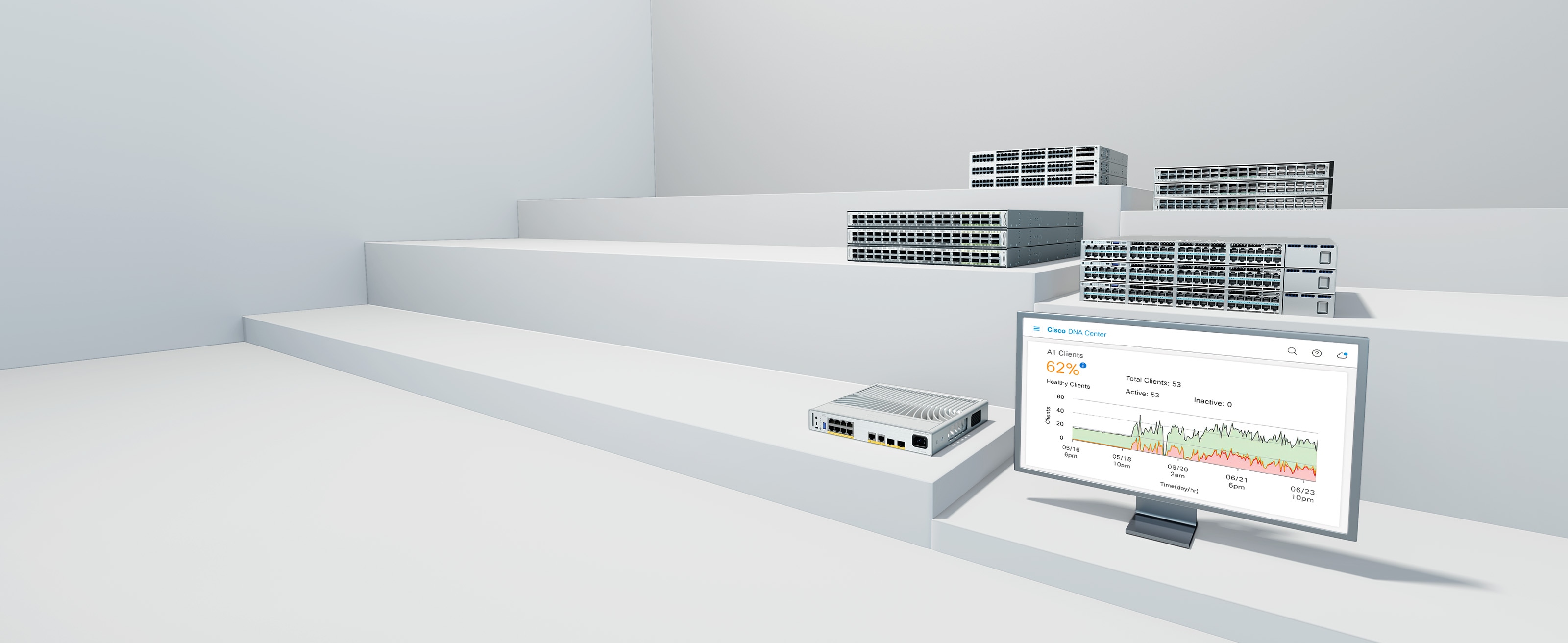
Provide top-notch experiences. Be a magnet for talent and innovation. Sharpen your edge over the competition. Let our switches—new and existing—help you do it all.
Low power consumption, quiet acoustic design, and shallow rack depth options, enabling deployment flexibility in wiring closets as well as in offices and classrooms
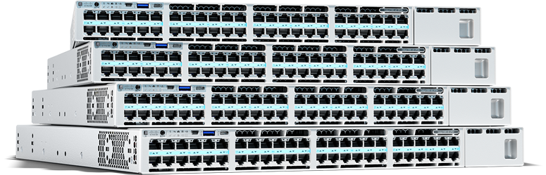
Easy-to-manage, enterprise-grade switches that provide excellent performance and advanced security needed for small and medium-sized businesses at an affordable price