Catalyst 4500-X Fan Assembly Installation Note
Available Languages
Table Of Contents
Catalyst 4500-X Fan Assembly Installation Note
Statement 1071—Warning Definition
Obtaining Documentation and Submitting a Service Request
Catalyst 4500-X Fan Assembly Installation Note
Revised: May 24, 2012
This document covers removing and installing a fan assembly in the Catalyst 4500-X series switch chassis.
Contents
This installation note contains the following sections
•
Obtaining Documentation and Submitting a Service Request
Fan Assembly Features
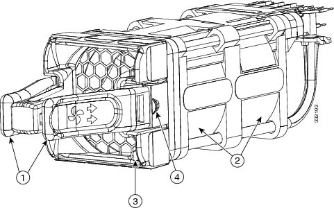
The Catalyst 4500-X series switch chassis has five fan assemblies located in individual bays at the back of the chassis. Each fan assembly can be removed and replaced individually. The Catalyst 4500-X switch normally operates with all five fans running. In the event of a single fan assembly failure, the chassis can continue to operate normally for extended periods of time. However fan redundancy is no longer available. In the event that another fan fails, the chassis shuts down. We recommend that you replace a failed fan assembly as soon as possible in order to maintain fan redundancy. Figure 1 shows the major features of a fan assembly.
Figure 1 Fan Assembly Features

Fan assembly release levers (color-coded for airflow direction. Burgundy indicates front-to-back; blue indicates back-to-front)
Fan status LED (red/green)
Fans
Fan assembly retention latch
The fan assembly has one unlabeled LED mounted on the lower right corner of the fan assembly front panel. (See Figure 1.) The LED provides the status of the individual fan assembly.

Note
An additional fan status LED is located on the chassis front panel. This LED provides a general status of all five fan assemblies in the chassis.
Shipping box dimensions and shipping weight for a spare fan assembly (C4KX-FAN-R= or C4KX-FAN-F=) are listed in Table 2.
Safety
Warning statements in the document use the following conventions:
Statement 1071—Warning Definition
Removing a Fan Assembly

Note
The chassis can operate normally for extended periods of time on four fan assemblies. However, the chassis no longer has fan redundancy. An additional fan assembly failure (two fan assemblies inoperative) will shut the system down. We recommend that you replace a faulty fan assembly as soon as possible in order to maintain five operating fan assemblies and fan redundancy.
To remove a fan assembly, follow these steps:
Step 1
Grasp the two fan assembly release levers between your thumb and forefinger and squeeze to release the fan assembly from the chassis. (See Figure 2.)
Step 2
Slide the fan assembly out of the chassis and set it aside.
Figure 2 Removing a Fan Assembly

Step 3
Install the replacement fan assembly following the procedure in the next section.
Installing a Fan Assembly
To install a fan assembly, follow these steps:
Step 1
Remove the fan assembly from the shipping packaging and discard the packaging.
Step 2
Verify that the new fan assembly has the correct airflow direction (front-to-back or back-to-front) for your situation. The fan assembly release levers (see Figure 1), are color-coded burgundy for front-to-back airflow or blue for back-to-front airflow.

Note
The chassis determines which airflow direction is correct by polling all of the fan assemblies and the power supplies. The airflow direction for all of the devices must be the same. If the airflow direction of the replacement fan assembly does not match the other fan assemblies airflow direction or the power supply airflow direction, the system software shuts down the power supply and generates an error message to the console.
Step 3
Position the fan assembly in front of the chassis fan assembly bay so that the fan assembly connector block is on top at the back of the assembly and the fan status LED is in the lower right corner of the fan assembly front panel. (See Figure 3.) Slide the fan assembly into the chassis.

Note
The fan assembly is keyed to prevent incorrect insertion.
Figure 3 Inserting the Fan Assembly into the Chassis

Step 4
Press your thumb firmly on the pad between the fan assembly release levers to seat the fan assembly in the chassis. (See Figure 4.)
Figure 4 Seating the Fan Assembly in the Chassis

Step 5
The fan automatically starts once it is fully seated in the chassis. Visually verify that the fan is operating correctly by monitoring the fan assembly LED.
Related Documentation
Table 3 lists the documentation supporting the Catalyst 4500-X series switch that is available on cisco.com.
Table 3 Documentation Supporting the Catalyst 4500-X Series Switch
Catalyst 4500-X Series Switch Installation Note
Contains instructions for rack-mounting the switch chassis.
Catalyst 4500-X 8-Port Network Uplink Module Installation Note
Contains instructions for installing and removing the optional 8-port network uplink module in the Catalyst 4500-X chassis.
Catalyst 4500-X AC-Input Power Supply Installation Note
Contains instructions for removing and installing the AC-input power supply in the Catalyst 4500-X switch chassis. Also contains descriptions of the supported AC power cords.
Catalyst 4500-X DC-Input Power Supply Installation Note
Contains instructions for removing and installing the DC-input power supply in the Catalyst 4500-X switch chassis.
Regulatory Compliance and Safety Information for the Catalyst 4500-X Series Switch
Contains the regulatory compliance and safety information for the Catalyst 4500-X series switch chassis. Also includes language translations of the warnings that appear in the other Catalyst 4500-X series switch documentation.
Catalyst 4500 Series Switch Cisco IOS Software Configuration Guide, Release IOS XE 3.3.0SG(15.1(1)SG)
Contains instructions on how to configure the Catalyst 4500-X switch.
Catalyst 4500 Series Switch Cisco IOS Command Reference, Release IOS XE 3.3.0SG(15.1(1)SG)
Contains descriptions of all of the software commands available that support the Catalyst 4500-X switch.
Release Notes for the Catalyst 4500 Series Switch, Release IOS XE 3.3.0SG(15.1(1)SG)
Contains the latest software caveats and workarounds related to the Catalyst 4500-X switch.
Obtaining Documentation and Submitting a Service Request
For information on obtaining documentation, submitting a service request, and gathering additional information, see the monthly What's New in Cisco Product Documentation, which also lists all new and revised Cisco technical documentation, at:
http://www.cisco.com/en/US/docs/general/whatsnew/whatsnew.html
Subscribe to the What's New in Cisco Product Documentation as an RSS feed and set content to be delivered directly to your desktop using a reader application. The RSS feeds are a free service. Cisco currently supports RSS Version 2.0.
This document is to be used in conjunction with the documents listed in the section.
Cisco and the Cisco logo are trademarks or registered trademarks of Cisco and/or its affiliates in the U.S. and other countries. To view a list of Cisco trademarks, go to this URL: www.cisco.com/go/trademarks. Third-party trademarks mentioned are the property of their respective owners. The use of the word partner does not imply a partnership relationship between Cisco and any other company. (1110R)
Any Internet Protocol (IP) addresses and phone numbers used in this document are not intended to be actual addresses and phone numbers. Any examples, command display output, network topology diagrams, and other figures included in the document are shown for illustrative purposes only. Any use of actual IP addresses or phone numbers in illustrative content is unintentional and coincidental.
© 2012 Cisco Systems, Inc. All rights reserved.

Contact Cisco
- Open a Support Case

- (Requires a Cisco Service Contract)


 Feedback