Catalyst 6500 Series Switch Installation Guide
Bias-Free Language
The documentation set for this product strives to use bias-free language. For the purposes of this documentation set, bias-free is defined as language that does not imply discrimination based on age, disability, gender, racial identity, ethnic identity, sexual orientation, socioeconomic status, and intersectionality. Exceptions may be present in the documentation due to language that is hardcoded in the user interfaces of the product software, language used based on RFP documentation, or language that is used by a referenced third-party product. Learn more about how Cisco is using Inclusive Language.
- Updated:
- August 31, 2010
Chapter: Preparing for Installation
- Safety
- Site Requirements
- Power Requirements
- Cabling Requirements
- Site Preparation Checklist
Preparing for Installation

Note![]() In this publication, the term Catalyst 6500 series refers only to the switch chassis listed in Chapter 1. The Catalyst 6000 series switches (Catalyst 6006 and Catalyst 6009 switches) are described in a separate publication, the Catalyst 6000 Series Switch Installation Guide.
In this publication, the term Catalyst 6500 series refers only to the switch chassis listed in Chapter 1. The Catalyst 6000 series switches (Catalyst 6006 and Catalyst 6009 switches) are described in a separate publication, the Catalyst 6000 Series Switch Installation Guide.
Planning a proper location for the switch and the layout of your equipment rack or wiring closet is essential for successful system operation. You should install the switch in an enclosed, secure area, ensuring that only qualified personnel have access to the switch and control of the environment. Equipment placed too close together or inadequately ventilated can cause system overtemperature conditions. In addition, poor equipment placement can make chassis panels inaccessible and difficult to maintain.
This chapter describes how to prepare your site for switch installation and contains these sections:
Safety
Safety warnings appear throughout this publication in procedures that may harm you if performed incorrectly. A warning symbol precedes each warning statement. The warnings below are general warnings that are applicable to the entire publication.

Warning![]() Only trained and qualified personnel should be allowed to install, replace, or service this equipment. Statement 1030
Only trained and qualified personnel should be allowed to install, replace, or service this equipment. Statement 1030
Warning![]() This unit is intended for installation in restricted access areas. A restricted access area can be accessed only through the use of a special tool, lock and key, or other means of security. Statement 1017
This unit is intended for installation in restricted access areas. A restricted access area can be accessed only through the use of a special tool, lock and key, or other means of security. Statement 1017
Warning![]() Before you install, operate, or service the system, read the Site Preparation and Safety Guide. This guide contains important safety information you should know before working with the system. Statement 200
Before you install, operate, or service the system, read the Site Preparation and Safety Guide. This guide contains important safety information you should know before working with the system. Statement 200
Warning![]() Voltages that present a shock hazard may exist on Power over Ethernet (PoE) circuits if interconnections are made using uninsulated exposed metal contacts, conductors, or terminals. Avoid using such interconnection methods, unless the exposed metal parts are located within a restricted access location and users and service people who are authorized within the restricted access location are made aware of the hazard. A restricted access area can be accessed only through the use of a special tool, lock and key or other means of security. Statement 1072
Voltages that present a shock hazard may exist on Power over Ethernet (PoE) circuits if interconnections are made using uninsulated exposed metal contacts, conductors, or terminals. Avoid using such interconnection methods, unless the exposed metal parts are located within a restricted access location and users and service people who are authorized within the restricted access location are made aware of the hazard. A restricted access area can be accessed only through the use of a special tool, lock and key or other means of security. Statement 1072
Site Requirements
These sections describe some of the basic site requirements that you should be aware of as you prepare to install your Catalyst 6500 series switch. Environmental factors can adversely affect the performance and longevity of your system. Planning a proper location for the switch and layout of your equipment rack or wiring closet is essential for successful system operation. You should install the switch in an enclosed, secure area, ensuring that only qualified personnel have access to the switch and control of the environment. Equipment that is placed too closely together or that is inadequately ventilated can cause system overtemperature conditions leading to premature component failures. In addition, poor equipment placement can make chassis panels inaccessible and difficult to maintain.
The switch requires a dry, clean, well-ventilated, and air-conditioned environment. To ensure normal operation, maintain ambient airflow. If the airflow is blocked or restricted, or if the intake air is too warm, an overtemperature condition can occur. The switch environmental monitor can then shut down the system to protect the system components.
Multiple switches can be rack-mounted with little or no clearance above and below the chassis. However, when mounting a switch in a rack with other equipment, or when placing it on the floor near other equipment, ensure that the exhaust from other equipment does not blow into the air intake vent of the switch chassis. Refer to Table 1-2 for specific air flow clearances needed.
Temperature
Temperature extremes can cause a system to operate at reduced efficiency and cause a variety of problems, including premature aging and failure of chips, and failure of mechanical devices. Extreme temperature fluctuations can cause chips to become loose in their sockets. Observe the following guidelines:
- Ensure that the system is operating in an environment no colder than 50°F (10°C) or hotter than 95°F (35°C).
- Ensure that the chassis has adequate ventilation.
- Do not place the chassis within a closed-in wall unit or on top of cloth, which can act as insulation.
- Do not place it where it will receive direct sunlight, particularly in the afternoon.
- Do not place it next to a heat source of any kind, including heating vents.
- Adequate ventilation is particularly important at high altitudes. Make sure that all slots and openings on the system remain unobstructed, especially the fan vent on the chassis.
- Clean the installation site at regular intervals to avoid buildup of dust and debris, which can cause a system to overheat.
- If the system has been exposed to abnormally cold temperatures, allow a 2-hour warm-up period to bring it up to normal operating temperature before turning it on.
Failure to observe these guidelines can damage internal components.
Note![]() The Catalyst 6500 series switches are equipped with internal air temperature sensors that are triggered at 104°F (40°C) generating a minor alarm and at 131°F (55°C) generating a major alarm.
The Catalyst 6500 series switches are equipped with internal air temperature sensors that are triggered at 104°F (40°C) generating a minor alarm and at 131°F (55°C) generating a major alarm.
Air Flow
The Catalyst 6500 series switch is designed to be installed in an environment where there is a sufficient volume of air available to cool the supervisor engines, modules, and power supplies. Any constraints placed on the free flow of air through the chassis or an elevated ambient air temperature can cause the switch to overheat and shut down.
To maintain proper air circulation through the Catalyst 6500 series switch chassis, we recommend that you maintain a minimum 6-inch (15 cm) separation between a wall and the chassis air intake or a wall and the chassis hot air exhaust. In situations where the switch chassis are installed in adjacent racks, you should allow a minimum of 12-inches (30.5 cm) between the air intake of one chassis and the hot air exhaust of another chassis. Failure to maintain adequate spacing between chassis can cause the switch chassis that is drawing in the hot exhaust air to overheat and fail. On Catalyst 6500 series chassis in which the airflow is from front to back, the chassis may be placed side-to-side.
If you are installing your Catalyst 6500 series switch in an enclosed or partially enclosed rack, we strongly recommend that you verify that your site meets the following guidelines:
- Verify that there is a minimum of 6 inches (15 cm) of clearance between the sides of the rack and both the chassis air intake grill and the chassis air exhaust grill.
- Verify that the ambient air temperature within the enclosed or partially enclosed rack is within the chassis operating temperature limits. After installing the chassis in the rack, power up the chassis and allow the chassis temperature to stabilize (approximately 2 hours). Measure the ambient air temperature at the chassis air intake grill and at the chassis air exhaust grill by positioning an external temperature probe approximately 1 inch (2.5 cm) away from the grills, in line with the chassis slot occupied by the supervisor engine.
–![]() If the ambient intake air temperature is less than 104°F (40°C), the rack meets the intake air temperature criterion.
If the ambient intake air temperature is less than 104°F (40°C), the rack meets the intake air temperature criterion.
–![]() If the ambient intake air temperature exceeds 104°F (40°C), the system might experience minor temperature alarms and is in danger of overheating.
If the ambient intake air temperature exceeds 104°F (40°C), the system might experience minor temperature alarms and is in danger of overheating.
–![]() If the ambient intake air temperature equals or is greater than 131°F (55°C), the system will experience a major temperature alarm and shut down.
If the ambient intake air temperature equals or is greater than 131°F (55°C), the system will experience a major temperature alarm and shut down.
- Verify that the enclosed or partially enclosed rack allows an adequate flow of air through the switch chassis as follows:
–![]() If the difference between the measured intake air temperature and the exhaust air temperature does not exceed 10°C, there is sufficient airflow in the rack.
If the difference between the measured intake air temperature and the exhaust air temperature does not exceed 10°C, there is sufficient airflow in the rack.
–![]() If the difference in air temperature exceeds 10°C, there is insufficient airflow to cool the chassis.
If the difference in air temperature exceeds 10°C, there is insufficient airflow to cool the chassis.
Note![]() The 10°C temperature differential between the intake and the exhaust must be determined by taking measurements using external digital temperature probes. Do not use the chassis internal temperature sensors to measure the temperature differential.
The 10°C temperature differential between the intake and the exhaust must be determined by taking measurements using external digital temperature probes. Do not use the chassis internal temperature sensors to measure the temperature differential.
- Plan ahead. Your Catalyst 6500 series switches currently installed in an enclosed or partially enclosed rack might meet ambient air temperature and air flow requirements now. However, if you add more chassis to the rack or you add more modules to a chassis in the rack, the additional heat generated might cause the ambient air temperature within the rack to exceed 104°F (40°C) and can cause minor alarms.
Selecting the Proper Rack-Enclosure or Cabinet
Cisco Systems has identified two rack-enclosures that are determined to be Cisco-compatible:
Panduit Corporation—The Net-Access Cabinet (p/n CN4-1) is determined to be Cisco-compatible for the Catalyst 6500 series product line. Contact Panduit Corporation for further information on this rack enclosure. Their corporate website is http://www.panduit.com. Their Customer Service and Technical Support phone number is 800 777-3300.
Chatsworth Products, Inc.—The N-Series TeraFrame Network Cabinet (p/n NF2K-113C-C42) is determined to be Cisco-compatible for the Catalyst 6500 series product line. Contact Chatsworth Products, Inc. for further information on this rack enclosure. Their corporate website is http://www.chatsworth.com. Their Customer Service and Technical Support phone number is 800 834-4969 (Monday to Friday, 5 a.m. to 5 p.m., (0500 to 1700) Pacific Time).
Chassis Fan Trays
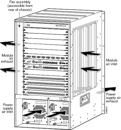
The chassis fan assembly provides cooling air for the supervisor engine and the switching modules. Table 1-1 lists the Catalyst 6500 series switch chassis along with the supported and unsupported fan trays. Table 1-2 lists the chassis air flow architecture and requirements for the Catalyst 6500 series switches. If an individual fan within the assembly fails, the FAN STATUS LED turns red. Individual fans within a fan tray assembly cannot be replaced; you must replace the entire fan tray assembly. To replace a fan tray assembly, see the “Removing and Installing the Fan Tray” section.
Refer to your software configuration guide for information on environmental monitoring.
|
|
|
|
|---|---|---|
| WS-6509-NEB-UPGRD1 (high speed) |
||
|
|
|
|
|
|
|
|
|---|---|---|---|---|---|---|
| Optional high-speed fan tray2 |
||||||
Catalyst 6509-NEB-A3 |
Yes4 |
|||||
Catalyst 6509-V-E 2 |
Yes 3 |
|||||
Figure 1-1 Catalyst 6503 and Catalyst 6503-E Switch Internal Airflow
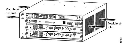
Figure 1-2 Catalyst 6504-E Switch Internal Airflow
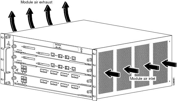
Figure 1-3 Catalyst 6506 Switch Internal Airflow
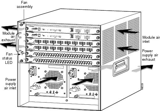
Figure 1-4 Catalyst 6506-E Switch Internal Airflow
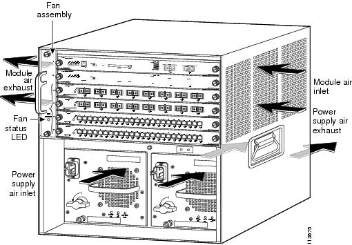
Figure 1-5 Catalyst 6509 Switch Internal Airflow
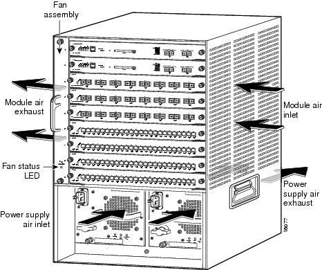
Figure 1-6 Catalyst 6509-E Switch Internal Airflow

Figure 1-7 Catalyst 6509-NEB Switch Internal Airflow

Figure 1-8 Catalyst 6509-NEB-A and Catalyst 6509-V-E Switch Internal Airflow

Figure 1-9 Catalyst 6513 Switch Internal Airflow
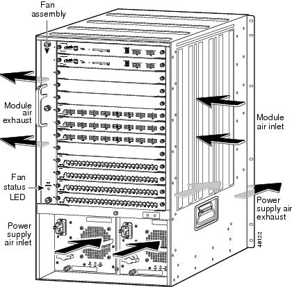
Figure 1-10 Catalyst 6513-E Switch Internal Airflow
Humidity
High-humidity conditions can cause moisture migration and penetration into the system. This moisture can cause corrosion of internal components and degradation of properties such as electrical resistance, thermal conductivity, physical strength, and size. Extreme moisture buildup inside the system can result in electrical shorts, which can cause serious damage to the system. Each system is rated to operate at 8 to 80 percent relative humidity, with a humidity gradation of 10 percent per hour. In storage, a system can withstand from 5 to 95 percent relative humidity. Buildings in which climate is controlled by air-conditioning in the warmer months and by heat during the colder months usually maintain an acceptable level of humidity for system equipment. However, if a system is located in an unusually humid location, a dehumidifier can be used to maintain the humidity within an acceptable range.
Altitude
Operating a system at high altitude (low pressure) reduces the efficiency of forced and convection cooling and can result in electrical problems related to arcing and corona effects. This condition can also cause sealed components with internal pressure, such as electrolytic capacitors, to fail or perform at reduced efficiency. Each system is rated to operate at altitudes from –50 to 6500 feet (–16 to 1981 meters) and can be stored at altitudes of –50 to 35,000 feet (–16 to 10,668 meters).
Dust and Particles
Fans cool power supplies and system components by drawing in room temperature air and exhausting heated air out through various openings in the chassis. However, fans also ingest dust and other particles, causing contaminant buildup in the system and increased internal chassis temperature. A clean operating environment can greatly reduce the negative effects of dust and other particles, which act as insulators and interfere with the mechanical components in the system. The standards listed below provide guidelines for acceptable working environments and acceptable levels of suspended particulate matter:
Corrosion
Corrosion of system connectors is a gradual process that can eventually lead to intermittent failures of electrical circuits. The oil from a person’s fingers or prolonged exposure to high temperature or humidity can corrode the gold-plated edge connectors and pin connectors on various components in the system. To prevent corrosion, avoid touching contacts on boards and cards, and protect the system from extreme temperatures and moist, salty environments.
Electromagnetic and Radio Frequency Interference
Electromagnetic interference (EMI) and radio frequency interference (RFI) from a system can adversely affect devices such as radio and television (TV) receivers operating near the system. Radio frequencies emanating from a system can also interfere with cordless and low-power telephones. Conversely, RFI from high-power telephones can cause spurious characters to appear on the system monitor. RFI is defined as any EMI with a frequency above 10 kilohertz (kHz). This type of interference can travel from the system to other devices through the power cable and power source or through the air like transmitted radio waves. The Federal Communications Commission (FCC) publishes specific regulations to limit the amount of EMI and RFI emitted by computing equipment. Each system meets these FCC regulations. To reduce the possibility of EMI and RFI, follow these guidelines:
- Only operate the system with the chassis covers installed.
- Ensure that all chassis slots are covered by a metal filler bracket and that an unused power supply bay has a metal cover plate installed.
- Ensure that the screws on all peripheral cable connectors are securely fastened to their corresponding connectors on the back of the chassis.
- Always use shielded cables with metal connector shells for attaching peripherals to the system.
When wires are run for any significant distance in an electromagnetic field, interference can occur between the field and the signals on the wires. This fact has two implications for the construction of plant wiring:
- Bad wiring practice can result in radio interference emanating from the plant wiring.
- Strong EMI, especially when it is caused by lightning or radio transmitters, can destroy the signal drivers and receivers in the chassis, and even create an electrical hazard by conducting power surges through lines into equipment.
Note![]() To predict and remedy strong EMI, you may also need to consult experts in radio frequency interference (RFI).
To predict and remedy strong EMI, you may also need to consult experts in radio frequency interference (RFI).
If you use twisted-pair cable in your plant wiring with a good distribution of grounding conductors, the plant wiring is unlikely to emit radio interference. If you exceed the recommended distances, use a high-quality twisted-pair cable with one ground conductor for each data signal when applicable.

If the wires exceed the recommended distances, or if wires pass between buildings, give special consideration to the effect of a lightning strike in your vicinity. The electromagnetic pulse caused by lightning or other high-energy phenomena can easily couple enough energy into unshielded conductors to destroy electronic devices. If you have had problems of this sort in the past, you may want to consult experts in electrical surge suppression and shielding.
Shock and Vibration
Catalyst 6500 series switches have been shock- and vibration-tested for operating ranges, handling, and earthquake standards to NEBS (Zone 4 per GR-63-Core). These tests have been conducted in earthquake environment and criteria, office vibration and criteria, transportation vibration and criteria, and packaged equipment shock.
Power Source Interruptions
Systems are especially sensitive to variations in voltage supplied by the AC power source. Overvoltage, undervoltage, and transients (or spikes) can erase data from memory or even cause components to fail. To protect against these types of problems, power cables should always be properly grounded. Also, place the system on a dedicated power circuit (rather than sharing a circuit with other heavy electrical equipment). In general, do not allow the system to share a circuit with any of the following:
- Copy machines
- Air conditioners
- Vacuum cleaners
- Space heaters
- Power tools
- Teletype machines
- Laser printers
- Facsimile machines
- Any other motorized equipment
Besides these appliances, the greatest threats to a system power supply are surges or blackouts that are caused by electrical storms. Whenever possible, turn off the system and any peripherals, and unplug them from their power sources during thunderstorms. If a blackout occurs—even a temporary one—while the system is turned on, turn off the system immediately and disconnect it from the electrical outlet. Leaving the system on may cause problems when the power is restored; all other appliances left on in the area can create large voltage spikes that can damage the system.
System Grounding
You must install a NEBS-compliant system ground as part of the chassis installation process. Chassis installations that rely only on the AC third-prong ground are insufficient to properly and adequately ground the systems.
Proper grounding practices ensure that the buildings and the installed equipment within them have low-impedance connections and low-voltage differentials between chassis. When you include NEBS-compliant system grounds, you reduce or prevent shock hazards, greatly reduce the chances of equipment damage due to transients, and substantially reduce the potential for data corruption.
Without proper and complete system grounding you run the risk of increased component damage due to ESD. Additionally, you have a greatly increased chance of data corruption, system lockup and frequent system reboot situations by not using a system (NEBS compliant) ground.
Table 1-3 lists some general grounding practice guidelines.
Note![]() In all situations, grounding practices must comply with Section 250 of the National Electric Code (NEC) requirements or local laws and regulations. A 6 AWG grounding wire is preferred from the chassis to the rack ground or directly to the common bonding network (CBN). The equipment rack should also be connected to the CBN with 6 AWG grounding wire.
In all situations, grounding practices must comply with Section 250 of the National Electric Code (NEC) requirements or local laws and regulations. A 6 AWG grounding wire is preferred from the chassis to the rack ground or directly to the common bonding network (CBN). The equipment rack should also be connected to the CBN with 6 AWG grounding wire.
Note![]() In installations where FXS modules are installed, supplemental grounding is required.
In installations where FXS modules are installed, supplemental grounding is required.
Note![]() Always ensure that all of the modules are completely installed and that the captive installation screws are fully tightened. In addition, ensure that all I/O cables and power cords are properly seated. These practices are normal installation practices and must be followed in all installations.
Always ensure that all of the modules are completely installed and that the captive installation screws are fully tightened. In addition, ensure that all I/O cables and power cords are properly seated. These practices are normal installation practices and must be followed in all installations.
Maintaining Safety with Electricity
When working on electrical equipment, follow these guidelines:
- Do not work alone if potentially hazardous conditions exist anywhere in your work space.
- Never assume that power is disconnected from a circuit; always check the circuit before working on it.
- Look carefully for possible hazards in your work area, such as damp floors, ungrounded power extension cables, frayed or damaged power cords, and missing safety grounds.
- If an electrical accident occurs, proceed as follows:
–![]() Use extreme caution; do not become a victim yourself.
Use extreme caution; do not become a victim yourself.
–![]() Disconnect power from the system.
Disconnect power from the system.
–![]() If possible, send another person to get medical aid. Otherwise assess the condition of the victim, and then call for help.
If possible, send another person to get medical aid. Otherwise assess the condition of the victim, and then call for help.
–![]() Determine if the person needs rescue breathing or external cardiac compressions; then take appropriate action.
Determine if the person needs rescue breathing or external cardiac compressions; then take appropriate action.
- Use the product within its marked electrical ratings and product usage instructions.
- Install the product in compliance with local and national electrical codes.
- If any of the following conditions occur, contact the Cisco Technical Assistance Center:
–![]() The power cable or plug is damaged.
The power cable or plug is damaged.
–![]() An object has fallen into the product.
An object has fallen into the product.
–![]() The product has been exposed to water or other liquids.
The product has been exposed to water or other liquids.
–![]() The product has been dropped or shows signs of damage.
The product has been dropped or shows signs of damage.
–![]() The product does not operate correctly when you follow the operating instructions.
The product does not operate correctly when you follow the operating instructions.
- Use the correct external power source. Operate the product only from the type of power source indicated on the electrical ratings label. If you are not sure of the type of power source required, consult the Cisco Technical Assistance Center or a local electrician.
- Use approved power cables only. You have been provided with one or more power cables with your chassis power supply that are intended for use in your country, based on the shipping location. Should you need to purchase additional power cables, ensure that they are rated for the product and for the voltage and current marked on the product’s electrical ratings label. The voltage and current rating of the power cable should be greater than the ratings marked on the label.
- To help prevent electrical shock, plug all power cables into properly grounded electrical outlets. These power cables are equipped with three-prong plugs to help ensure proper grounding. Do not use adapter plugs or remove the grounding prong from a power cable.
- Observe power strip ratings. Make sure that the total current rating of all products that are plugged into the power strip does not exceed 80 percent of the power strip rating.
- Do not modify power cables or plugs yourself. Consult with a licensed electrician or your power company for site modifications. Always follow your local and national wiring codes.
Preventing Electrostatic Discharge Damage
Electrostatic discharge (ESD) damage, which can occur when modules or other FRUs are improperly handled, results in intermittent or complete failures. Modules consist of printed circuit boards that are fixed in metal carriers. Electromagnetic interference (EMI) shielding and connectors are integral components of the carrier. Although the metal carrier helps to protect the board from ESD, always use an ESD grounding strap when handling modules.
To prevent ESD damage, follow these guidelines:
- Always use an ESD wrist strap and ensure that it makes maximum contact with bare skin. ESD grounding straps are available with banana plugs, metal spring clips, or alligator clips. All Catalyst 6500 series chassis are equipped with a banana plug connector (identified by the ground symbol next to the connector) somewhere on the front panel. If you have an older Catalyst 6500 series chassis equipped with a plastic banana plug connector, we recommend that you use either the supplied ESD grounding wrist strap (with a metal clip) or an ESD grounding wrist strap equipped with an alligator clip. If you have a newer Catalyst 6500 series chassis that has a bare metal hole as the banana plug connector (also identified by the ground symbol next to the connector), we recommend that you use a personal ESD grounding strap equipped with a banana plug.
- If you choose to use the disposable ESD wrist strap supplied with most FRUs or an ESD wrist strap equipped with an alligator clip, you must attach the system ground lug to the chassis in order to provide a proper grounding point for the ESD wrist strap.
Note![]() This system ground is also referred to as the network equipment building system (NEBS) ground.
This system ground is also referred to as the network equipment building system (NEBS) ground.
- If your chassis does not have the system ground attached, you must install the system ground. See “Establishing the System Ground” section for installation instructions and locations of the chassis system ground pads.
After you install the system ground lug, follow these steps to correctly attach the ESD wrist strap:
Step 1![]() Attach the ESD wrist strap to bare skin as follows:
Attach the ESD wrist strap to bare skin as follows:
a.![]() If you are using the ESD wrist strap supplied with the FRUs, open the wrist strap package and unwrap the ESD wrist strap. Place the black conductive loop over your wrist and tighten the strap so that it makes good contact with your bare skin.
If you are using the ESD wrist strap supplied with the FRUs, open the wrist strap package and unwrap the ESD wrist strap. Place the black conductive loop over your wrist and tighten the strap so that it makes good contact with your bare skin.
b.![]() If you are using an ESD wrist strap equipped with an alligator clip, open the package and remove the ESD wrist strap. Locate the end of the wrist strap that attaches to your body and secure it to your bare skin.
If you are using an ESD wrist strap equipped with an alligator clip, open the package and remove the ESD wrist strap. Locate the end of the wrist strap that attaches to your body and secure it to your bare skin.
Step 2![]() Grasp the spring or alligator clip on the ESD wrist strap and momentarily touch the clip to a bare metal spot (unpainted surface) on the rack. We recommend that you touch the clip to an unpainted rack rail so that any built-up static charge is then safely dissipated to the entire rack.
Grasp the spring or alligator clip on the ESD wrist strap and momentarily touch the clip to a bare metal spot (unpainted surface) on the rack. We recommend that you touch the clip to an unpainted rack rail so that any built-up static charge is then safely dissipated to the entire rack.
Step 3![]() Attach either the spring clip or the alligator clip to the ground lug screw as follows (See Figure 1-11):
Attach either the spring clip or the alligator clip to the ground lug screw as follows (See Figure 1-11):
a.![]() If you are using the ESD wrist strap that is supplied with the FRUs, squeeze the spring clip jaws open, position the spring clip to one side of the system ground lug screw head, and slide the spring clip over the lug screw head so that the spring clip jaws close behind the lug screw head.
If you are using the ESD wrist strap that is supplied with the FRUs, squeeze the spring clip jaws open, position the spring clip to one side of the system ground lug screw head, and slide the spring clip over the lug screw head so that the spring clip jaws close behind the lug screw head.
Note![]() The spring clip jaws do not open wide enough to fit directly over the head of the lug screw or the lug barrel.
The spring clip jaws do not open wide enough to fit directly over the head of the lug screw or the lug barrel.
b.![]() If you are using an ESD wrist strap that is equipped with an alligator clip, attach the alligator clip directly over the head of the system ground lug screw or to the system ground lug barrel.
If you are using an ESD wrist strap that is equipped with an alligator clip, attach the alligator clip directly over the head of the system ground lug screw or to the system ground lug barrel.
Figure 1-11 Attaching the ESD Wrist Strap Clip to the System Ground Lug Screw

When handling modules, follow these guidelines:
- Handle carriers by available handles or edges only; avoid touching the printed circuit boards or connectors.
- Place a removed component board-side-up on an antistatic surface or in a static shielding container. If you plan to return the component to the factory, immediately place it in a static shielding container.
- Never attempt to remove the printed circuit board from the metal carrier.
Power Requirements
When preparing your site for the switch installation, follow these requirements:
- In systems configured with two power supplies, connect each of the two power supplies to a separate input power source. If you fail to do this, your system might be susceptible to total power failure due to a fault in the external wiring or a tripped circuit breaker.
- To prevent a loss of input power, be sure that the total maximum load on each source circuit is within the current ratings of the wiring and breakers.
- In some systems, you may decide to use an uninterruptible power supply (UPS) to protect against power failures at your site. Be aware when selecting a UPS that some UPS models that use ferroresonant technology can become unstable when operating with the Catalyst 6500 series switch power supplies which use power factor correction (PFC). This can cause the output voltage waveform to the switch to become distorted resulting in an undervoltage situation in the system.
- The AC-input power supply has a detachable power cord (except for the 4000 W power supplies) that allows you to connect each power supply to the site power source. The 4000 W AC-input power supply power cords are hard-wired to the power supply and cannot be removed.
- You can connect the DC-input power supply to the power source with heavy-gauge wiring connected to a terminal block. The wire gauge size is determined by local electrical codes and restrictions.
- If you are using a 200/240 VAC power source in North America, the circuit must be protected by a two-pole circuit breaker.
- The source AC outlet must be within 6 feet (1.8 meters) of the system and should be easily accessible.
- The AC power receptacles used to plug in the chassis must be the grounding type. The grounding conductors that connect to the receptacles should connect to protective earth ground at the service equipment.
Power Connection Guidelines for AC-Powered Systems
This section provides the basic guidelines for connecting the Catalyst 6500 series switch AC power supplies to the site power source:
–![]() The 950 W power supply requires a 15 A circuit.
The 950 W power supply requires a 15 A circuit.
–![]() The 1000 W power supply requires a 15 A or 20 A circuit.
The 1000 W power supply requires a 15 A or 20 A circuit.
–![]() The 1300 W, 1400 W, 2500 W, 2700 W, and 3000 W power supplies require a 20 A circuit.
The 1300 W, 1400 W, 2500 W, 2700 W, and 3000 W power supplies require a 20 A circuit.
–![]() The 4000 W power supply requires a 30 A circuit.
The 4000 W power supply requires a 30 A circuit.
–![]() The 6000 W power supply requires one or two 20 A circuits.
The 6000 W power supply requires one or two 20 A circuits.
–![]() The 8700 W power supply requires one, two, or three 20 A circuits.
The 8700 W power supply requires one, two, or three 20 A circuits.
–![]() Circuits should be sized according to local and national codes.
Circuits should be sized according to local and national codes.
- If you are using a 200/240 VAC power source in North America, the circuit must be protected by a two-pole circuit breaker.
- The source AC outlet must be within 6 feet (1.8 meters) of the system and should be easily accessible.
- The AC power receptacles used to plug in the chassis must be the grounding type. The grounding conductors that connect to the receptacles should connect to protective earth ground at the service equipment.
Power Connection Guidelines for DC-Powered Systems
This section provides the basic guidelines for connecting the Catalyst 6500 series switch DC-input power supplies to the site power source:
- All power connection wiring should conform to the rules and regulations in the National Electrical Code (NEC), as well as any local codes.
- The DC return must remain isolated from the system frame and the chassis (DC-I).
- For DC power cables, we recommend that you use commensurately rated, high-strand-count copper wire cable. Connection to the DC-input power supply requires one earth ground cable, one source DC (–), and one source DC return (+). The length of the cables depends on your switch location. These cables are not available from Cisco Systems. They are available from any commercial cable vendor.
- The color coding of the source DC power cable leads depends on the color coding of the site DC power source. Typically, green or green and yellow indicate that the cable is a ground cable. Because there is no color code standard for source DC wiring, you must ensure that the power cables are connected to the DC-input power supply terminal block in the proper (+) and (–) polarity. In some cases, the source DC cable leads might have a positive (+) or a negative (–) label. This label is a relatively safe indication of the polarity, but you must verify the polarity by measuring the voltage between the DC cable leads. When making the measurement, the positive (+) lead and the negative (–) lead must always match the (+) and (–) labels on the DC-input power supply terminal block.
- DC power cables must be terminated by cable lugs at the power supply end.
- The circuit breaker is considered to be the disconnect device and should be easily accessible.
- The circuit must be protected by a dedicated two-pole circuit breaker. The circuit breaker should be sized according to the power supply input rating and local or national code requirements.
- For proper DC-input redundant power configurations on systems with multiple-input DC-input power supplies, all pairs of source DC cables for one DC-input power supply must come from the same battery system (A feed); all pairs of source DC cables for the second DC-input power supply must come from a different battery system (B feed).
- For DC-input power supplies with multiple inputs, each DC input must be protected by a dedicated circuit breaker or a fuse. The circuit breaker or the fuse must be sized according to the power supply input rating and local or national electrical codes.
Cabling Requirements
When running power and data cables together in overhead cable trays or subfloor cable trays, be aware of the following caution:
Also be aware of the following caution concerning the use of Category 5e and Category 6 Ethernet cables:
Site Preparation Checklist
Table 1-4 lists the site planning activities that you should perform prior to installing the Catalyst 6500 series switch. Completing each activity helps ensure a successful switch installation.
|
|
|
|
|
|
|---|---|---|---|---|
 Feedback