OC-12 ATM Module Memory Installation Note
Available Languages
Table Of Contents
Catalyst 6500 Series Switch OC-12 ATM Module Memory Installation Note
Installing the OC-12 ATM Memory Kit
Installing the OC-12 ATM Module
Obtaining Documentation and Submitting a Service Request
Catalyst 6500 Series Switch OC-12 ATM Module Memory Installation Note
Product Number: WS-OC12-32M-KIT=
This publication describes how to install the Catalyst 6500 series OC-12 ATM module memory kit.
Contents
This publication consists of these sections:
•
Installing the OC-12 ATM Memory Kit
•
Obtaining Documentation and Submitting a Service Request

Note
For translations of the warnings in this publication, see the "Translated Safety Warnings" section.
Safety Overview
Safety warnings appear throughout this publication in procedures that may harm you if performed incorrectly. A warning symbol precedes each warning statement.
Installing the OC-12 ATM Memory Kit
The section is divided into the following topics:
•
Removing the OC-12 ATM Module
•
Installing the OC-12 ATM Module

Warning
Only trained and qualified personnel should be allowed to install, replace, or service this equipment.
Required Tools
The following tools are required to perform the memory module installation procedure:
•
Number 1 and number 2 Phillips screwdrivers
•
Antistatic mat or antistatic foam
•
Your own ESD-prevention equipment or the disposable grounding wrist strap (included in the memory kit)
Removing the OC-12 ATM Module

CautionDuring this procedure, wear grounding wrist straps and handle the module by the carrier edges only to avoid ESD damage to the module.

Warning
Do not work on the system or connect or disconnect cables during periods of lightning activity.
To remove the OC-12 ATM module from the chassis, perform these steps:
Step 1
Disconnect any network interface cables attached to the module.
Step 2
Verify that the captive installation screws on all of the modules in the chassis are tight. This step ensures that the space created by the removed module is maintained.

Note
If the captive installation screws are loose, the EMI gaskets on the installed modules will push the modules toward the open slot, reducing the opening size and making it difficult to reinstall the module.
Step 3
Loosen the two captive screws on the module to be removed.
Step 4
Depending on the orientation of the slots in the chassis (horizontal or vertical), perform one of the following two sets of steps:
Horizontal slots
a.
Place your thumbs on the left and right ejector levers, and simultaneously rotate the levers outward to unseat the module from the backplane connector. (See Figure 1.)
b.
Grasp the front edge of the module, and slide the module part of the way out of the slot. Place your other hand under the module to support the weight of the module. Do not touch the module circuitry. (See Figure 2.)
Vertical slots
a.
Place your thumbs on the ejector levers located at the top and bottom of the module, and simultaneously rotate the levers outward to unseat the module from the backplane connector.
b.
Grasp the edges of the module, and slide the module straight out of the slot. Do not touch the module circuitry.
Step 5
Place the module on an antistatic mat or antistatic foam.
Figure 1 Opening the Ejector Levers (Horizontal Chassis Shown)

Figure 2 Removing the Module from the Chassis (Horizontal Chassis Shown)

Installing the DRAM DIMMs
The WS-OC12-32M-KIT= memory kit contains two 16-MB DRAM DIMMS that are installed in a DIMM socket located on the OC-12 ATM module. (See Figure 3.)

CautionDIMMs are sensitive components that are susceptible to ESD damage. To prevent ESD damage, always wear an ESD wrist strap and handle the DIMMs by their edges only; avoid touching the memory modules, pins, or traces (the metal fingers along the connector edge of the DIMM).

Note
The DIMM socket supports two DIMMs, one stacked on top of the other. Install the bottom DIMM first, then install the top DIMM.
Figure 3 OC-12 ATM Module DRAM DIMM Socket Location

To install the two DRAM DIMMs, perform the following steps:
Step 1
Remove one DRAM DIMM from the antistatic package.
Step 2
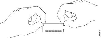
Hold the DIMM by its edges. (See Figure 4.)
Figure 4 Handling a DIMM

Step 3
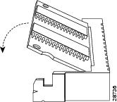
Tilt the DIMM to approximately the same angle as the socket, and insert the connector edge into the bottom set of connectors in the socket. Note the notch (key) on the right connector edge of the DIMM. (See Figure 5.) This key assures correct orientation of the DIMM in the socket.

CautionWhen inserting the DIMM, use firm but not excessive pressure. If you damage a socket, you will have to return the OC-12 ATM module to Cisco for repair.
Figure 5 Installing the DIMM

Step 4
Press the DIMM down until it is secured by the spring clips. (See Figure 5.)
Step 5
When the DIMM is installed, check the two alignment holes and ensure that the spring retainer is visible. If it is not, the DIMM is not seated properly. If the DIMM appears misaligned, carefully remove it and reseat it in the socket. Push the DIMM firmly back into the socket until the retainer springs snap into place.
Step 6
Remove the second DRAM DIMM from the antistatic packageand repeat Step 2 through Step 5 for the second (upper) DIMM.
Installing the OC-12 ATM Module

CautionTo prevent ESD damage, handle modules by the carrier edges only and wear a grounding wrist strap.
To reinstall the OC-12 ATM module in the chassis, follow these steps:
Step 1
Verify that the captive installation screws are tightened on all modules installed in the chassis. This action assures that the EMI gaskets on all modules are fully compressed in order to maximize the opening space for the removed module.

Note
If the captive installation screws are loose, the EMI gaskets on the installed modules will push adjacent modules toward the open slot, reducing the opening size and making it difficult to install the removed module.
Step 2
Fully open both ejector levers on the module being installed. (See Figure 6.)
Figure 6 Positioning the Module in a Horizontal Slot Chassis

Step 3
Depending on the orientation of the slots in the chassis (horizontal or vertical), perform one of the following two sets of steps:
Horizontal slots
a.
Position the module in the slot. (See Figure 6.) Make sure that you align the sides of the module carrier with the slot guides on each side of the slot.
b.
Carefully slide the module into the slot until the EMI gasket along the top edge of the module makes contact with the module in the slot above it and both ejector levers have closed to approximately 45 degrees with respect to the module faceplate.
c.
Using the thumb and forefinger of each hand, grasp the two ejector levers, and press down to create a small 0.040 inch (1 mm) gap between the module's EMI gasket and the module above it. (See Figure 7.)

Note
Do not press down too forcefully on the levers because they will bend and get damaged.
Figure 7 Clearing the EMI Gasket in a Horizontal Slot Chassis

d.
While pressing down, simultaneously close the left and right ejector levers to fully seat the module in the backplane connector. The ejector levers are fully closed when they are flush with the module faceplate.

Note
Failure to fully seat the module in the backplane connector can result in error messages.
e.
Tighten the two captive installation screws on the module.

Note
Make sure that the ejector levers are fully closed before tightening the captive installation screws.
f.
Verify that the module STATUS LED is lit. Periodically check the STATUS LED. If the STATUS LED changes from orange to green, the module has successfully completed the boot process and is now online. If the STATUS LED remains orange or turns red, the module has not successfully completed the boot process and may have encountered an error.
Vertical slots
a.
Position the module in the slot. (See Figure 8.) Make sure that you align the sides of the module carrier with the slot guides on the top and bottom of the slot.
Figure 8 Positioning the Module in a Vertical Slot Chassis

b.
Carefully slide the module into the slot until the EMI gasket along the right edge of the module makes contact with the module in the slot adjacent to it and both ejector levers have closed to approximately 45 degrees with respect to the module faceplate. (See Figure 9.)
c.
Using the thumb and forefinger of each hand, grasp the two ejector levers and exert a slight pressure to the left, deflecting it approximately 0.040 inches (1 mm) to create a small gap between the module's EMI gasket and the module adjacent to it. (See Figure 9.)

Note
Do not exert too much pressure on the ejector levers because they will bend and get damaged.
Figure 9 Clearing the EMI Gasket in a Vertical Slot Chassis

d.
While pressing down on the ejector levers, simultaneously close the levers to fully seat the module in the backplane connector. The ejector levers are fully closed when they are flush with the module faceplate.
e.
Tighten the two captive installation screws on the module.

Note
Make sure that the ejector levers are fully closed before tightening the captive installation screws.
f.
Verify that the module STATUS LED is lit. Periodically check the STATUS LED. If the STATUS LED changes from orange to green, the module has successfully completed the boot process and is now online. If the STATUS LED remains orange or turns red, the module has not successfully completed the boot process and may have encountered an error.
Translated Safety Warnings
This section repeats in multiple languages the basic warnings that appear in this publication.
Installation Warning
Lightning Activity Warning
Obtaining Documentation and Submitting a Service Request
For information on obtaining documentation, submitting a service request, and gathering additional information, see the monthly What's New in Cisco Product Documentation, which also lists all new and revised Cisco technical documentation, at:
http://www.cisco.com/en/US/docs/general/whatsnew/whatsnew.html
Subscribe to the What's New in Cisco Product Documentation as a Really Simple Syndication (RSS) feed and set content to be delivered directly to your desktop using a reader application. The RSS feeds are a free service and Cisco currently supports RSS Version 2.0.
This document is to be used in conjunction with the Catalyst 6500 Series Switch Module Installation Guide.
CCIP, CCSP, the Cisco Arrow logo, the Cisco Powered Network mark, the Cisco Systems Verified logo, Cisco Unity, Follow Me Browsing, FormShare, iQ Net Readiness Scorecard, Networking Academy, and ScriptShare are trademarks of Cisco Systems, Inc.; Changing the Way We Work, Live, Play, and Learn, The Fastest Way to Increase Your Internet Quotient, and iQuick Study are service marks of Cisco Systems, Inc.; and Aironet, ASIST, BPX, Catalyst, CCDA, CCDP, CCIE, CCNA, CCNP, Cisco, the Cisco Certified Internetwork Expert logo, Cisco IOS, the Cisco IOS logo, Cisco Press, Cisco Systems, Cisco Systems Capital, the Cisco Systems logo, Empowering the Internet Generation, Enterprise/Solver, EtherChannel, EtherSwitch, Fast Step, GigaStack, Internet Quotient, IOS, IP/TV, iQ Expertise, the iQ logo, LightStream, MGX, MICA, the Networkers logo, Network Registrar, Packet, PIX, Post-Routing, Pre-Routing, RateMUX, Registrar, SlideCast, SMARTnet, StrataView Plus, Stratm, SwitchProbe, TeleRouter, TransPath, and VCO are registered trademarks of Cisco Systems, Inc. and/or its affiliates in the U.S. and certain other countries.
All other trademarks mentioned in this document or Web site are the property of their respective owners. The use of the word partner does not imply a partnership relationship between Cisco and any other company. (0303R)
Copyright © 2003 Cisco Systems, Inc. All rights reserved.
Contact Cisco
- Open a Support Case

- (Requires a Cisco Service Contract)


 Feedback