Installing a Compact Switch

Shipping Box Contents

The shipping box contains the model of the switch you ordered and other components needed for installation. Some components are optional, depending on your order.


Note


Verify that you have received these items. If any item is missing or damaged, contact your Cisco representative or reseller for instructions. Verify that you have received these items. If any item is missing or damaged, contact your Cisco representative or reseller for instructions.


Figure 1. Components Delivered in the Shipping Box
Components delivered in the shipping box

1

Cisco Catalyst 9200CX Series switch

8

(Optional) Two 19-inch mounting brackets (RACKMNT-19-CMPACT=)*

2

(Optional) AC power cord * 1

(An AC power cord is available to order with AC-powdered switches. For C9200CX-12T-2X2G, a power cord is available with C9K-80W-ADPT, if ordered. A power cord is not available with C9K-ADPT-DC.)

9

(Optional) Two 23-inch mounting brackets (RCKMNT-23-CMPCT)*

3

Four rubber mounting feet

10

(Optional) Desk mount (C9K-CMPCT-DESK-MNT)*

4

(Optional) DIN rail mount (C9K-CMPCT-DIN-MNT)*

11

(Optional) Magnet and mounting tray (C9K-MGNT-TRAY)*

5

(Optional) Wall mount tray (C9K-WALL-TRAY)*

12

(Optional) Auxiliary Power Adapter (C9K-ADPT-DC)*
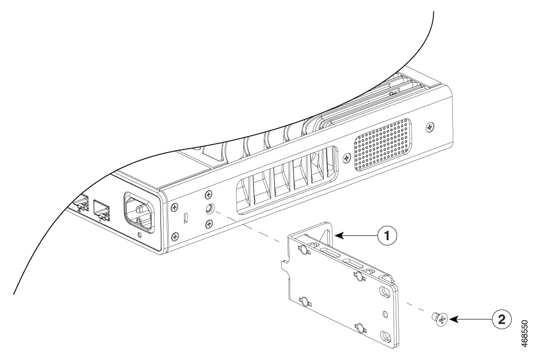
6

(Optional) Power adapter bracket (C9K-ADPT-BRKT-12T)*

13

(Optional) Power cord retainer (C9K-CMPCT-PWR-CLP)*

7

(Optional) Cable guide (C9K-CMPCT-CBLE-GRD)*

14

(Optional) USB Type B to RJ45 adapter (CAB-CON-USBRJ45)*

1 * Item is orderable.

Mounting the Switch

The following sections explain the different mounting options.

Mounting on a Desk or Shelf Without Mounting Screws

Procedure


Step 1

Locate the adhesive strip with the rubber feet in the accessory kit.

Step 2

Remove the four rubber feet from the adhesive strip, and attach them to the locations indicated at the bottom of the unit. This prevents the switch from sliding on the desk or shelf.


Note

 
We strongly recommend that you attach the rubber feet to the specified location and place the side of the switch with Cisco logo facing upwards. Doing so helps prevent airflow restriction and overheating.

Step 3

Place the switch on the desk or the shelf.


Mounting using the Mounting Tray and Screws

You can use the mounting tray to secure the switch on to a desk or a wall. The illustrations in this procedure shows how to mount the switch on a desk. You can follow similar procedure to mount the switch on a wall.


Caution


Do not wall-mount the switch with its front panel facing up. Following safety regulations, wall-mount the switch with its front panel facing down or to the side, to allow sufficient airflow and to provide easier access to the cables.


Note


To avoid thermal issues, do no use this mounting method for under-table scenarios.


Before you begin

Ensure you have the following items before starting the procedure.
  • Mounting tray (C9K-WALL-TRAY)

  • Three 8-18 Phillips pan-head screws

  • Two 10-32 Phillips pan-head screws

  • Screwdriver

Procedure


Step 1

Place the mounting tray on to the mounting surface.

Step 2

Use a 0.144-in. (3.7 mm) or a #27 drill bit to drill three holes, 1/2-inches (12.7 mm) deep in the desk.

Step 3

Insert the three 8-18 Phillips pan-head screws in to the slots on the mounting tray, and tighten them.

Figure 2. Attaching the Mounting Tray to the Desk or Shelf


1

Three 8-18 Phillips pan-head screws

3

Desk

2

Mounting tray

-

-

Step 4

Place the switch on the mounting tray, slide it slightly forward so that the mounting tray hooks on both the sides engage with the switch.

Figure 3. Aligning the Mounting Tray Hooks with the Switch


1

Switch

3

Mounting tray

2

Mounting tray hook

-

-

Step 5

Secure the switch to the mounting tray using the screws provided.

Figure 4. Securing the Switch to the Mounting Tray


1

Two 10-32 Phillips pan-head screws

2

Switch


Mounting using the Mounting Tray and Magnet

This topic explains the steps to use a magnet with the mounting tray to mount the switch on a metal surface. The illustrations used in the procedure shows how to mount the switch on a metal desk. You can use a similar procedure to mount the switch on a metal wall or under a metal desk.


Caution


Do not use the magnet without a mounting tray.

Before you begin

Ensure you have the following accessories available.
  • Mounting tray and magnet for compact switches (C9K-MGNT-TRAY)

  • Two 10-32 Phillips pan-head screws

  • Phillips screwdriver

Procedure


Step 1

Place one side of the magnet against the bottom of the mounting tray.

Figure 5. Placing the Mounting Tray on the Magnet


1

Mounting tray

2

Magnet

Step 2

Slide the switch slightly forward after placing on to the mounting tray so that the mounting tray hooks engage with the switch.

Figure 6. Aligning the Mounting Tray Hooks with the Switch


1

Switch

3

Mounting tray

2

Mounting tray hook

-

-

Step 3

Place the switch on the mounting tray and secure it using the two 10-32 Phillips pan-head screws.

Figure 7. Securing the Switch to the Mounting Tray


1

Two 10-32 Phillips pan-head screws

-

-

Step 4

Mount the magnet and the switch on a metal surface.

Warning


Read the wall-mounting instructions carefully before beginning installation. Failure to use the correct hardware or to follow the correct procedures could result in a hazardous situation to people and damage to the system.

Caution


Do not wall-mount the switch with its front panel facing up. Following safety regulations, wall-mount the switch with its front panel facing down or to the side, to allow sufficient airflow and to provide easier access to the cables.

DANGER


Ensure that you mount the switch in an enclosed and secure area. Pulling the cables hard or an occurrence of a seismic event can cause the magnet to dislodge from the mounting surface and cause bodily harm.


Mounting Under a Desk or a Shelf

Before you begin

Ensure you have the following items before starting the procedure.
  • Desk mount (C9K-CMPCT-DESK-MNT)

  • Three 8-18 Phillips pan-head screws

  • Two 10-32 Phillips pan-head screws

  • Screwdriver

Procedure


Step 1

Use the desk mount to align the screw holes and also as a guide to make sure that you install the screws under the desk or shelf with proper clearance.

Step 2

Use a 0.144-inch (3.7 mm) or a #27 drill bit to drill three holes, 1/2-inches (12.7 mm) deep on the desk or shelf.

Step 3

Insert the screws in to the slots on the desk mount, and tighten them.

Figure 8. Installing the Desk Mount Under a Desk or a Shelf


1

Desk

3

Three 8-18 Phillips pan-head screws

2

Desk mount

-

-

Step 4

Place the switch on the mounting tray, slide it slightly forward so that the mounting tray hooks on both the sides engage with the switch.

Figure 9. Aligning the Mounting Tray Hooks with the Switch


1

Switch

3

Mounting tray

2

Mounting tray hook

-

-

Step 5

Secure the switch to the desk mount using the two 10-32 Phillips pan-head screws provided.

Figure 10. Mounting the Switch Under a Desk or Shelf


1

Two 10-32 Phillips pan-head screws

-

-


Figure 11. The Switch in Installed Position


Mounting the Switch Using Rack Mount Brackets

Before you begin

Ensure you have the following:

  • 19-Inch Rack Mounting Brackets (RACKMNT-19-CMPCT)

  • 10-32 Phillips flat-head screws

  • Number-12 or number-10 Phillips machine screws

  • Phillips screwdriver

Procedure


Step 1

Secure the brackets to the switch by attaching one Phillips flat-head screws on each side of the switch.

Figure 12. Attaching Brackets for 19-inch Racks


1

19-inch rack-mounting bracket

2

10-32 Phillips flat-head screws

Step 2

Secure the brackets to the rack by attaching the supplied Phillips machine screws, two screws on each sides.

Figure 13. Attaching the Brackets to the Rack


1

Number-12 or number-10 Phillips machine screws

2

Rack post


Mounting the Switch on a DIN Rail


Caution


Do not install the switch with its front panel facing up. Following safety regulations, install the switch with its front panel facing down, to allow sufficient airflow and to provide easier access to the cables.


Before you begin

Ensure you have the following:
  • DIN Rail Mount (C9K-CMPCT-DIN-MNT)

  • 10-32 Phillips flat-head screws

  • Phillips screwdriver

Procedure


Step 1

Place the DIN rail mount on the DIN rail, making sure that the top of the DIN rail mount clip hooks over the top of the DIN rail.

Step 2

Sliding the release tab downwards, hook the clip on to the rail and release the tab until the rail mount clip locks into place with a click.

Figure 14. Attaching the DIN Rail Mount to the DIN Rail


1

DIN rail mount

3

Release tab

2

DIN rail

Note


Note that the DIN rail is not part of the DIN Rail Mount kit.

-

-

Step 3

Place the switch on to the DIN rail mount and secure it using the two 10-32 Phillips pan-head screws.

Figure 15. Securing the Switch to the DIN Rail


1

10-32 Phillips pan-head screws

-

-


Connecting the System Ground

To establish an earth ground for the switch, you must attach a grounding cable from the chassis’ grounding lug to the rack.
Figure 16. Connecting the System Ground

Procedure


Step 1

Use a wire-stripping tool to remove approximately 0.5 inch (12.7 mm) ± 0.02 inch (0.5 mm) of the covering from the end of the grounding wire.

Step 2

Insert the stripped end of the grounding wire into the open end of the grounding lug.

Step 3

Crimp the grounding wire in the barrel of the grounding lug. Verify that the ground wire is securely attached to the ground lug.

Step 4

Place the grounding wire lug against the grounding pad, making sure that there is solid metal-to-metal contact.

Step 5

Secure the grounding lug to the switch with the grounding screw. Ensure that the grounding lug and the grounding wire do not interfere with other switch hardware or rack equipment.

Figure 17. Attaching the Grounding Lug


1

Location of the system ground lug

3

3/8" length 10-32 screw

2

Grounding lug

-

-

Step 6

Connect the other end of the grounding wire to an appropriate grounding point at your site or to the rack.


Attaching the Adapter Bracket to the Switch (Optional)

If you are using an auxiliary power adapter to power the switch which is placed on a mounting tray or a DIN rail mount, you can use the optional power adapter bracket to secure the power adapter. You can order the power adapter bracket (C9K-ADPT-BRKT-12T) from your Cisco representative.

Before you begin

  • Power adapter

  • Power adapter bracket (C9K-ADPT-BRKT-12T)

  • One 8-18 Phillips pan-head screws

  • Two M3x6mm pan head screw

  • Phillips screwdriver

Procedure


Step 1

Thread the velcro straps through the slots on the adapter bracket that corresponds to the size of the adapter. You can thread the strap based on the size of the power adapter. The following illustration displays some examples.

Figure 18. Threading the Velcro Strap through the Adapter Bracket


Step 2

Attach the power adapter bracket using the two M3 x 6 mm Phillips pan head screws provided. The adapter bracket can be fixed in different positions to suit the size of the adapter used.

Figure 19. Attaching the Power Adapter Bracket


1

M3 x 6 mm Phillips pan head screws

3

Adapter bracket

2

8-18 x 0.5" Phillips pan head tapping screw

4

Mounting tray

Note

 
The power adapter bracket cannot be used without a mounting tray or a DIN rail mount.

Step 3

Place the adapter into the power adapter bracket and secure it using the velcro straps provided.

Figure 20. Securing the Power Adapter to the Adapter Bracket


1

Power adapter

2

Velcro strap


Installing the Power Cord Retainer (Optional)


Note


This section applies to switches with an AC power connector.


Before you begin

  • The power cord retainer (C9K-CMPCT-PWR-CLP) is optional. You can order it when you order your switch, or you can order it later from your Cisco representative.

Procedure


Step 1

Fix the power cord retainer strap to the switch using the M3 pan-head screw provided.

Figure 21. Attaching the Power Cord Retainer Strap


1

M3x6mm pan-head screw

2

Power cord retainer strap

Step 2

Slide the retainer clamp around the AC power cord and position it closest to the connector on the adapter.

Note


Depending on the width of the power cord, adjust the size of the retainer clamp, if required.

Figure 22. Sliding the Retainer Clamp Through the Power Cord


1

AC power cord connector

2

Power cord retainer clamp

Step 3

Insert the retainer strap through the latch at the bottom of the clamp and press the tabs on the retainer clamp towards each other to secure the power cord.

Figure 23. Locking the Retainer Clamp


1

Pressing the tabs on the retainer clamp

-

-


Installing the Cable Guard (Optional)

The cable guard prevents tampering with the cables after they are installed. The cable guard (C9K-CMPCT-CBLE-GRD=) is not included with the switch, but you can order it from your Cisco representative.


Note


You can use the cable guard when the switch is mounted on a wall.


The cable guard is shipped with the following items:

  • Two 10-32 Phillips pan-head screws

  • Two 8-18 Phillips pan-head screws

Procedure


Step 1

Use the supplied 10-32 pan-head screws to attach the cable guard to the switch.

Figure 24. Attaching the Cable Guard to the Switch


1

Cable Guard

2

Two 10-32 pan-head screws

Step 2

Pivot the cable guide upwards and install the cables.

Figure 25. Pivoting the Cable Guard Upwards


1

Cable guard

2

Pivot direction for cable guard

Step 3

Guide the connected cables through the slots in the front of the cable guard and pivot the cable guide back to the original position as shown in the following figure.

Step 4

Lock the cable guide in the installed position using the two 8-18 Phillips pan-head screws provided.

Figure 26. Switch with Cable Guide Installed


1

Two 8-18 Phillips pan-head screws

-

-


Installing an SFP or SFP+ Module

Before you begin

When installing SFP or SFP+ modules, observe these guidelines:

  • Do not remove the dust plugs from the modules or the rubber caps from the fiber-optic cable until you are ready to connect the cable. The plugs and caps protect the module ports and cables from contamination and ambient light.

  • To prevent ESD damage, follow your normal board and component handling procedures when connecting cables to the switch and other devices.


    Caution


    Removing and installing an SFP or SFP+ module can shorten its useful life. Do not remove and insert any module more often than is absolutely necessary.


    Warning


    This product is a Class 1 laser product.


Procedure


Step 1

Attach an ESD-preventive wrist strap to your wrist and to a bare metal surface.

Step 2

Find the send (TX) and receive (RX) markings on the module top.

On some SFP or SFP+ modules, the send and receive (TX and RX) markings might be replaced by arrows that show the direction of the connection.

Step 3

If the module has a bale-clasp latch, move it to the open, unlocked position.

Step 4

Align the module in front of the slot opening, and push until you feel the connector snap into place.

Figure 27. Installing an SFP Module


Step 5

If the module has a bale-clasp latch, close it.

Step 6

For fiber-optic SFP or SFP+ modules, remove the dust plugs and save.

Step 7

Connect the required cables.


10/100/1000 PoE and PoE+ Port Connections

The ports provide PoE support for devices compliant with IEEE 802.3af and 802.3at (PoE+), and also provide Cisco prestandard PoE support for Cisco IP Phones and Cisco Aironet Access Points.

On a per-port basis, you can control whether or not a port automatically provides power when an IP phone or an access point is connected.

To access an advanced PoE planning tool, use the Cisco Power Calculator available on Cisco.com at this URL: http://tools.cisco.com/cpc/launch.jsp

You can use this application to calculate the power supply requirements for a specific PoE configuration. The results show output current, output power, and system heat dissipation.


Caution


Category 5e and Category 6 cables can store high levels of static electricity. Always ground the cables to a suitable and safe earth ground before connecting them to the switch or other devices.


Caution


Noncompliant cabling or powered devices can cause a PoE port fault. Use only standard-compliant cabling to connect Cisco prestandard IP Phones and wireless access points, IEEE 802.3af, or 802.3at (PoE+) compliant devices. You must remove any cable or device that causes a PoE fault.


Procedure


Step 1

Connect one end of the cable to the switch PoE port.

Step 2

Connect the other end of the cable to an RJ-45 connector on the other device. The port LED turns on when both devices have established link.

The port LED is amber while STP discovers the topology and searches for loops. This process takes about 30 seconds, and then the port LED turns green. If the LED is off, the other device might not be turned on, there might be a cable problem, or there might be a problem with the adapter in the other device.

Step 3

Reconfigure and reboot the connected device, if needed.

Step 4

Repeat Steps 1 through 3 to connect each device.

Note


Many legacy powered devices, including older Cisco IP phones and access points that do not fully support IEEE 802.3af, might not support PoE when connected to the switches by a crossover cable.


10/100/1000 Ethernet Port Connections

The switch 10/100/1000 port configuration changes to operate at the speed of the attached device. If the attached ports do not support autonegotiation, you can manually set the speed and duplex parameters. Connecting devices that do not autonegotiate or that have the speed and duplex parameters manually set can reduce performance or result in no linkage.

To maximize performance, choose one of these methods for configuring the Ethernet ports:

  • Let the ports autonegotiate both speed and duplex.

  • Set the interface speed and duplex parameters on both ends of the connection.

Auto-MDIX Connections

The autonegotiation and the auto-MDIX features are enabled by default on the switch.

With autonegotiation, the switch port configurations change to operate at the speed of the attached device. If the attached device does not support autonegotiation, you can manually set the switch interface speed and duplex parameters.

With auto-MDIX, the switch detects the required cable type for copper Ethernet connections and configures the interface accordingly.

If auto-MDIX is disabled, use the guidelines in this table to select the correct cable.

Table 1. Recommended Ethernet Cables (When Auto-MDIX is Disabled)

Device

Crossover Cable

Straight-Through Cable

Switch to switch

Yes

No

Switch to hub

Yes

No

Switch to computer or server

No

Yes

Switch to router

No

Yes

Switch to IP phone

No

Yes

2 100BASE-TX and 1000BASE-T traffic requires twisted four-pair, Category 5 or higher. 10BASE-T traffic can use Category 3 cable or higher.