The documentation set for this product strives to use bias-free language. For the purposes of this documentation set, bias-free is defined as language that does not imply discrimination based on age, disability, gender, racial identity, ethnic identity, sexual orientation, socioeconomic status, and intersectionality. Exceptions may be present in the documentation due to language that is hardcoded in the user interfaces of the product software, language used based on RFP documentation, or language that is used by a referenced third-party product. Learn more about how Cisco is using Inclusive Language.
Configuring Multi-Homing in a BGP EVPN VXLAN Fabric
Restrictions for Multi-Homing in a BGP EVPN VXLAN Fabric
Multi-homing in all-active redundancy mode is not supported.
Multi-homing in single-active redundancy mode supports only dual-homing, which allows two nodes within a redundancy group.
Cross-linking between host or access devices and VTEPs is not supported for a dual-homed network.
A dual-homed network needs internal redundancy to avoid a network split.
Provision and operational state of EVPN instances must be consistent on both dual-homed VTEPs. Inconsistencies in configuration
or operational state of EVPN instances between the VTEPs leads to traffic blackholing.
Do not configure EVPN-enabled VLAN and non-EVPN-enabled VLAN on an ethernet segment enabled trunk interface. This is because
spanning tree protocol (STP) is disabled at the interface level when an ethernet segment is enabled, and may cause Layer 2
loops in non-EVPN-enabled VLANs.
Information About Multi-Homing in a BGP EVPN VXLAN Fabric
Multi-homing feature in a BGP EVPN VXLAN fabric provides redundancy in the connection between a host or Layer 2 switch and
the EVPN VXLAN network.
In a BGP EVPN VXLAN fabric, you connect a host or Layer 2 switch to the EVPN VXLAN network either through single-homing or
through multi-homing.
Single-Homing
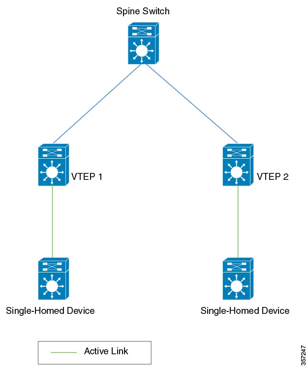
Single-homing allows you to connect a host or Layer 2 switch to a single VTEP in the EVPN VXLAN network. Single-homing does
not support redundancy in the connection between the host or access device and the VTEP. When the active link breaks down,
the connection between the host (or Layer 2 switch) and the VTEP is lost. As a result, single-homed topologies are not always
reliable and efficient.
The following figure shows a single-homed topology:
Figure 1. Single-Homed Topology
Multi-Homing
Multi-homing allows you to connect a host or Layer 2 switch to more than one VTEP in the EVPN VXLAN network. This connection
provides redundancy and allows network optimization. Redundancy in the connection with the VTEPs ensures that there’s no traffic
disruption when there’s a network failure. Multi-homed topologies are more reliant, secure, and efficient than single-homed
topologies.
Multi-homing operates in single-active and all-active redundancy modes. In both modes, the connected host or access device
is represented by an ethernet segment ID. This ethernet segment ID must also be part of the configuration on the VTEP's interface
that connects the multihomed host or network device. All traffic forwarded between the VTEPs and the host (or Layer 2 switch)
passes through this ethernet segment.
Single-Active Redundancy Mode
In single-active redundancy mode, only a single VTEP, among a group of VTEPs that are attached to a particular Ethernet-segment,
is allowed to forward traffic to and from the Ethernet segment. It results in a single-active access link between the VTEPs
and the host (or Layer 2 switch) that passes through the Ethernet segment. The single access link can either be a physical
link or an ether-channel.
Multi-homing in single-active redundancy mode is supported only in the form of dual-homing. Dual-homing allows a host or access device to be connected to only two VTEPs. A dual-homed topology with single-active redundancy
can be deployed in one of the following ways:
Dual-homed device
Dual-homed network
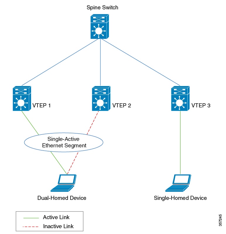
Dual-Homed Device
In single-active dual-homed device topology, a single host or access device is connected to two VTEPs with two links that
pass through a single-active Ethernet segment. The Ethernet segment contains two separate links connecting the host or access
device to each VTEP, but only one link remains active at any given time. For each VLAN interface on a dual-homed host or access
device, only one link remains active. When the active link breaks down, the back-up link takes over and ensures constant connectivity.
The following figure shows a dual-homed device topology:
Figure 2. Dual-Homed Device Topology
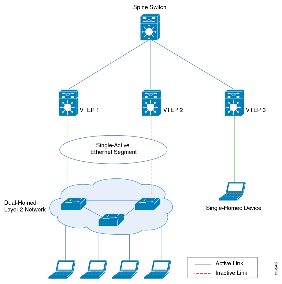
Dual-Homed Network
In single-active dual-homed network topology, two host or access devices from the same network are connected to two separate
VTEPs through links that pass through a single-active Ethernet segment. At any given time, only one of these links remains
active. When the active link breaks down, the back-up link takes over and ensures constant connectivity. The two host or access
devices are part of a dual-homed network.
A dual-homed network topology results in a situation where the network splits into two different networks if the connectivity
between the host or access devices is lost. To avoid this scenario, redundancy must also be enabled within the dual-homed
network.
The following figure shows a dual-homed network topology:
Note
Ensure that you enable a spanning tree within the dual-homed Layer 2 network.
Figure 3. Dual-Homed Network Topology
DF Election and Load Balance
A dual-homed network with a single-active Ethernet segment uses a Designated Forwarder (DF) election mechanism to load balance
the traffic. The DF election is made at the Layer 2 VNI level, when the access interface from the VTEP is a trunk interface
and an Ethernet segment is configured.
In the above topology, some Layer 2 VNIs use the interface connected to VTEP 1 as the active link and the others use the interface
connected to VTEP 2 as the active link. This allows effective utilization of bandwidth on both the interfaces in a steady
network state. Traffic in each Layer 2 VNI is load balanced for the downstream dual-homed Layer 2 network. If any of the physical
interface link to the downstream Layer 2 device goes down and is not operational, the DF election algorithm recalculates the
active link interface. After the link is reestablished and both links are operational again, the DF election algorithm restores
the load balancing operation to utilize the bandwidth of both the links effectively.
Migration Between Single-Homed and Multi-Homed Network Topologies
BGP EVPN VXLAN allows you to migrate your network topology from one redundancy mode to another. You can transition from a
single-homed topology to a multi-homed topology. Likewise, you can also remove the redundancy from a multi-homed topology
to move back to a single-homed topology.
Note
When you migrate from one topology to another, ensure you make corresponding changes to the Ethernet segment configuration.
If you change either of the two without making corresponding changes to the other, it results in traffic loops and traffic
blackholing.
How to Configure Multi-Homing in a BGP EVPN VXLAN Fabric
Before you configure multi-homing in a BGP EVPN VXLAN fabric, ensure that you configure EVPN VXLAN Layer 2 and Layer 3 overlay
networks. See for detailed steps.
Configuring Dual-Homing with Single Active Redundancy in a BGP EVPN VXLAN Fabric
To configure dual-homing with single-active redundancy in a BGP EVPN VXLAN fabric, perform the following set of procedures:
Configuring Redundancy on an Ethernet Segment
To configure redundancy on an ethernet segment, perform the following steps :
Associating an Ethernet Segment with an Interface on a VTEP
To associate the ethernet segment with an interface on a VTEP, perform the following steps :
Procedure
Command or Action
Purpose
Step 1
enable
Example:
Device> enable
Enters privileged EXEC mode.
Enter password, if prompted.
Step 2
configure terminal
Example:
Device# configure terminal
Enters global configuration mode.
Step 3
interface interface-id
Example:
Device(config)# interface GigabitEthernet1/0/10
Specifies the interface, and enters interface configuration mode.
Step 4
evpn ethernet-segment ethernet-segment-id
Example:
Device(config-if)# evpn ethernet-segment 1
Associates the specified Ethernet segment with the interface. Each Ethernet segment is represented by a unique Ethernet segment
ID.
Note
Ensure that you configure a unique Ethernet segment ID on any interface. Ensure that you configure the same segment ID on
the link that connects the second VTEP and the dual-homed device (the second link through the Ethernet segment).
Step 5
end
Example:
Device(config-if)# end
Exits interface configuration mode and enters privileged EXEC mode.
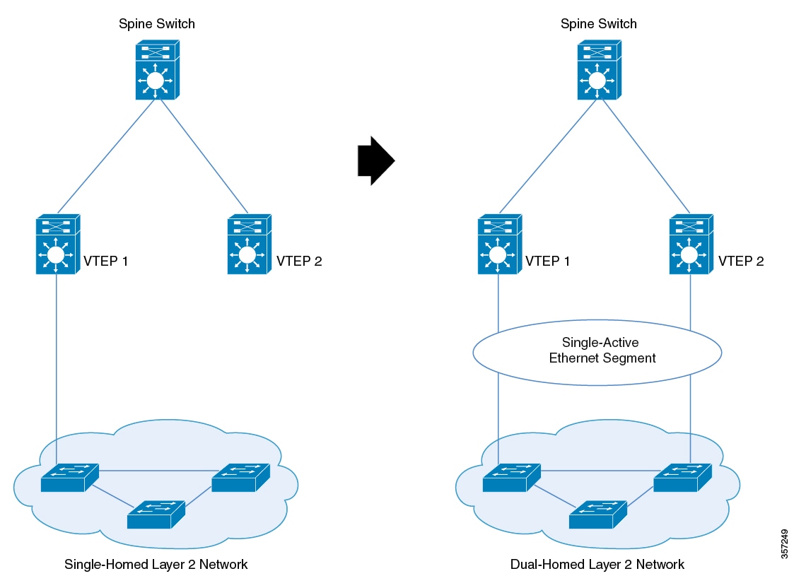
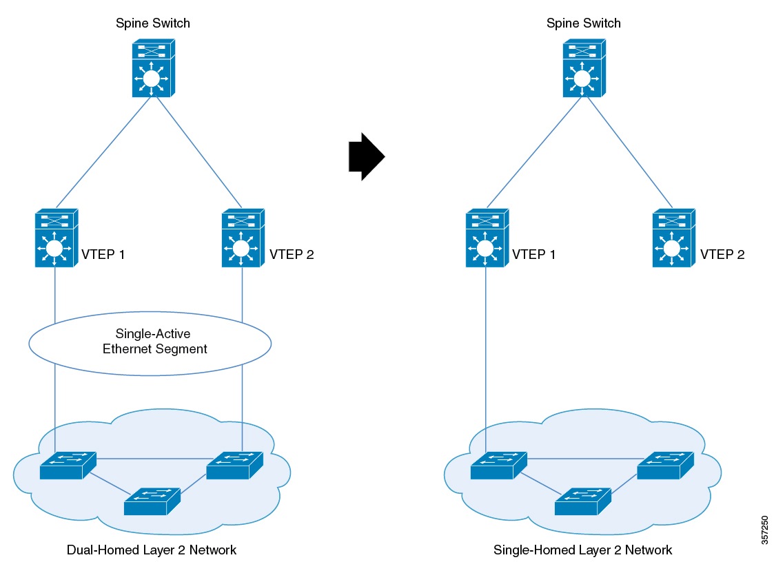
Migrating from a Single-Homed Topology to a Single-Active Dual-Homed Topology
The following figures illustrate the migration from a single-homed topology to a single-active dual-homed topology:
Figure 4. Migration from a Single-Homed Network to a Single-Active Dual-Homed Network
To migrate from a single-homed network to a single-active dual-homed network, perform the following steps:
Note
When you migrate from one topology to another, ensure you make corresponding changes to the Ethernet segment configuration.
If you change either of the two without making corresponding changes to the other, it results in traffic loops and traffic
blackholing.
Before you migrate, we recommend that you do not configure the VTEP as the root bridge of the spanning tree, as the provision
of Ethernet segment on the interface of a VTEP excludes it from spanning-tree. If the VTEP is the root bridge, its exclusion
from the spanning-tree triggers an immediate spanning tree re-convergence.
Note
Do not activate a link between VTEP 2 and a switch in the single-homed network yet. Activate the second only once you configure
the Ethernet segment. In case a link is already activated, ensure that you deactivate the link.
Provision the Ethernet segment on the interface of the VTEP that has the active link. Provision of the Ethernet segment updates
all the MAC addresses that are locally learned on that interface with the Ethernet segment ID of the interface.
Now provision the Ethernet segment on the interface of the second VTEP that needs to be connected to the switch in the single-homed
network.
Connect the link and bring up the interface of the second VTEP. By doing this, you trigger fast convergence, Ethernet segment
auto-discovery, and DF reelection.
The single-homed network has now migrated to a dual-homed network.
Migrating from a Single-Active Dual-Homed Topology to a Single-Homed Topology
The following figures illustrate the migration from a single-active dual-homed topology to a single-homed topology:
Figure 5. Migration from a Single-Active Dual-Homed Network to a Single-Homed Network
To migrate from a single-active dual-homed network to a single-homed network, perform the following steps:
Note
When you migrate from one topology to another, ensure you make corresponding changes to the Ethernet segment configuration.
If you change either of the two without making corresponding changes to the other, it results in traffic loops and traffic
blackholing.
Note
Ensure that the Ethernet segment remains configured on the dual-homed links as long as the links are up. If the Ethernet segment
is removed from an active link, it causes traffic loops.
Before you migrate, we recommended that you configure portfast on the link you activate. Removal of Ethernet segment from
an interface on the VTEP puts it back into the spanning-tree. If the interface is not configured with portfast, the port goes
through block-learn-forward states and causes extensive traffic loss.
Shut down the interface that needs to be decommissioned. When you shut down the interface, you trigger fast convergence, Ethernet
segment auto-discovery, and DF reelection. As a result, all the traffic converges into the active link.
Remove the Ethernet segment from the decommissioned interface. Ensure that the interface is down before you disconnect the
link.
The dual-homed network has now migrated to a single-homed network with an Ethernet segment.
(Optional) Remove the Ethernet segment from the interface with the active link on the VTEP.
Removal of the Ethernet segment updates all the MAC addresses that are locally learned on that interface without the Ethernet
segment ID.
The Ethernet segment is now removed from the single-homed network homed network.
Configuration Examples for Multi-Homing in a BGP EVPN VXLAN Fabric
This section provides configuration examples for multi-homing in a BGP EVPN VXLAN fabric:
Example: Configuring Dual-Homing with Single-Active Redundancy in a BGP EVPN VXLAN Fabric
This example shows how to configure and verify dual-homing with single-active redundancy in a BGP EVPN VXLAN fabric for the
following topology:
Figure 6. Dual-Homing with Single-Active Redundancy in a BGP EVPN VXLAN Fabric
The topology shows an EVPN VXLAN network with two spine switches (Spine Switch 1 and Spine Switch 2) and three VTEPs (VTEP
1, VTEP 2, and VTEP 3). Host Device 1 is connected to VTEP 1. Host Device 2 is connected to VTEP 2 and VTEP 3 as a dual-homed
single-active connection that passes through Ethernet Segment 1.
Note
Ensure that you configure a unique Ethernet segment ID on any interface in the fabric. If an Ethernet segment ID is associated
with one of the connecting links passing through the segment, associate the same Ethernet segment ID with the second link.
interface Loopback1
ip address 172.16.254.4 255.255.255.255
ip ospf 1 area 0
!
interface GigabitEthernet0/0
vrf forwarding Mgmt-vrf
ip address 10.62.149.182 255.255.255.0
negotiation auto
!
interface GigabitEthernet1/0/1
no switchport
ip address 172.16.14.4 255.255.255.0
ip ospf network point-to-point
ip ospf 1 area 0
!
interface GigabitEthernet1/0/2
no switchport
ip address 172.16.24.4 255.255.255.0
ip ospf network point-to-point
ip ospf 1 area 0
!
interface GigabitEthernet1/0/10
switchport access vlan 101
switchport mode access
evpn ethernet-segment 1
spanning-tree portfast
!
interface Vlan101
vrf forwarding green
ip address 10.1.101.1 255.255.255.0
no autostate
!
interface Vlan901
vrf forwarding green
ip unnumbered Loopback1
ipv6 enable
no autostate
!
interface nve1
no ip address
source-interface Loopback1
host-reachability protocol bgp
member vni 10101 ingress-replication
member vni 50901 vrf green
interface Loopback1
ip address 172.16.254.5 255.255.255.255
ip ospf 1 area 0
!
interface GigabitEthernet0/0
vrf forwarding Mgmt-vrf
ip address 10.62.149.183 255.255.255.0
negotiation auto
!
interface GigabitEthernet1/0/1
no switchport
ip address 172.16.15.5 255.255.255.0
ip ospf network point-to-point
ip ospf 1 area 0
!
interface GigabitEthernet1/0/2
no switchport
ip address 172.16.25.5 255.255.255.0
ip ospf network point-to-point
ip ospf 1 area 0
!
interface GigabitEthernet1/0/10
switchport access vlan 101
switchport mode access
evpn ethernet-segment 1
spanning-tree portfast
!
interface Vlan101
vrf forwarding green
ip address 10.1.101.1 255.255.255.0
!
interface Vlan901
vrf forwarding green
ip unnumbered Loopback1
ipv6 enable
no autostate
!
interface nve1
no ip address
source-interface Loopback1
host-reachability protocol bgp
member vni 10101 ingress-replication
member vni 50901 vrf green
Table 2. Configuring Spine Switch 1, Spine Switch 2, and VTEP 1 to Configure Dual-Homing with Single-Active Redundancy
Spine Switch 1
Spine Switch 2
VTEP 1
Spine-01# show running-config
hostname Spine-01
!
ip routing
!
system mtu 9198
!
interface Loopback0
ip address 172.16.255.1 255.255.255.255
ip ospf 1 area 0
!
interface GigabitEthernet0/0
vrf forwarding Mgmt-vrf
ip address 10.62.149.180 255.255.255.0
negotiation auto
!
interface GigabitEthernet1/0/1
no switchport
ip address 172.16.13.1 255.255.255.0
ip pim sparse-mode
ip ospf network point-to-point
ip ospf 1 area 0
!
interface GigabitEthernet1/0/2
no switchport
ip address 172.16.14.1 255.255.255.0
ip pim sparse-mode
ip ospf network point-to-point
ip ospf 1 area 0
!
interface GigabitEthernet1/0/3
no switchport
ip address 172.16.15.1 255.255.255.0
ip pim sparse-mode
ip ospf network point-to-point
ip ospf 1 area 0
!
router ospf 1
router-id 172.16.255.1
!
Leaf-01# show running-config
hostname Leaf-01
!
vrf definition green
rd 1:1
!
address-family ipv4
route-target export 1:1
route-target import 1:1
route-target export 1:1 stitching
route-target import 1:1 stitching
exit-address-family
!
address-family ipv6
route-target export 1:1
route-target import 1:1
route-target export 1:1 stitching
route-target import 1:1 stitching
exit-address-family
!
ip routing
!
l2vpn evpn
replication-type static
router-id Loopback1
default-gateway advertise
!
l2vpn evpn instance 101 vlan-based
encapsulation vxlan
replication-type ingress
!
!
system mtu 9198
!
vlan configuration 101
member evpn-instance 101 vni 10101
vlan configuration 901
member vni 50901
!
interface Loopback0
ip address 172.16.255.3 255.255.255.255
ip ospf 1 area 0
!
interface Loopback1
ip address 172.16.254.3 255.255.255.255
ip ospf 1 area 0
!
interface GigabitEthernet0/0
vrf forwarding Mgmt-vrf
ip address 10.62.149.179 255.255.255.0
negotiation auto
!
interface GigabitEthernet1/0/1
no switchport
ip address 172.16.13.3 255.255.255.0
ip ospf network point-to-point
ip ospf 1 area 0
!
interface GigabitEthernet1/0/2
no switchport
ip address 172.16.23.3 255.255.255.0
ip ospf network point-to-point
ip ospf 1 area 0
!
interface GigabitEthernet1/0/10
switchport access vlan 101
switchport mode access
spanning-tree portfast
!
interface Vlan101
vrf forwarding green
ip address 10.1.101.1 255.255.255.0
!
interface Vlan901
vrf forwarding green
ip unnumbered Loopback1
ipv6 enable
no autostate
!
interface nve1
no ip address
source-interface Loopback1
host-reachability protocol bgp
member vni 10101 ingress-replication
member vni 50901 vrf green
!
router ospf 1
router-id 172.16.255.3
!
Verifying Dual-Homing with Single-Active Redundancy in a BGP EVPN VXLAN Fabric
The following sections provide sample outputs for show commands to verify dual-homing with single-active redundancy on the devices in the topology configured above:
The following example shows the output for the show l2route evpn mac esi ethernet-segment-id command on VTEP 2:
Leaf-02# show l2route evpn mac esi 0001.0101.0101.0101.0101
  EVI       ETag  Prod    Mac Address                  Next Hop(s) Seq Number
----- ---------- ----- -------------- ---------------------------- ----------
  101          0   BGP 44d3.ca28.6c82         V:10101 172.16.254.5          0
  101          0   BGP 44d3.ca28.6cc2         V:10101 172.16.254.5          0

Leaf-02#
The following example shows the output for the show l2route evpn mac esi ethernet-segment-id detail command on VTEP 2:
Leaf-02# show l2route evpn mac esi 0001.0101.0101.0101.0101 detail
EVPN Instance:            101
Ethernet Tag:             0
Producer Name:            BGP
MAC Address:              44d3.ca28.6c82
Num of MAC IP Route(s):   0
Sequence Number:          0
ESI:                      0001.0101.0101.0101.0101
Flags:                    B()
Next Hop(s):              V:10101 172.16.254.5
Resolved Next Hops:       V:10101 172.16.254.5
Resolved Redundancy Mode: Single-Active

EVPN Instance:            101
Ethernet Tag:             0
Producer Name:            BGP
MAC Address:              44d3.ca28.6cc2
Num of MAC IP Route(s):   0
Sequence Number:          0
ESI:                      0001.0101.0101.0101.0101
Flags:                    B()
Next Hop(s):              V:10101 172.16.254.5
Resolved Next Hops:       V:10101 172.16.254.5
Resolved Redundancy Mode: Single-Active

Leaf-02#
The following example shows the output for the show bgp l2vpn evpn route-type command for route type 4 on VTEP 3:
Leaf-03# show bgp l2vpn evpn route-type 4
BGP routing table entry for [4][172.16.255.4:257][00010101010101010101][32][172.16.254.4]/23, version 337
Paths: (2 available, best #2, table EVPN-BGP-Table)
  Not advertised to any peer
  Refresh Epoch 5
  Local
    172.16.254.4 (metric 3) (via default) from 172.16.255.2 (172.16.255.2)
      Origin incomplete, metric 0, localpref 100, valid, internal
      Extended Community: ENCAP:8 EVPN ES-IMPORT:0x101:0x101:0x101
      Originator: 172.16.255.4, Cluster list: 172.16.255.2
      rx pathid: 0, tx pathid: 0
      Updated on Jan 26 2021 19:38:35 UTC
  Refresh Epoch 5
  Local
    172.16.254.4 (metric 3) (via default) from 172.16.255.1 (172.16.255.1)
      Origin incomplete, metric 0, localpref 100, valid, internal, best
      Extended Community: ENCAP:8 EVPN ES-IMPORT:0x101:0x101:0x101
      Originator: 172.16.255.4, Cluster list: 172.16.255.1
      rx pathid: 0, tx pathid: 0x0
      Updated on Jan 26 2021 19:38:35 UTC
BGP routing table entry for [4][172.16.255.5:257][00010101010101010101][32][172.16.254.5]/23, version 1269
Paths: (1 available, best #1, table EVPN-BGP-Table)
  Advertised to update-groups:
     2
  Refresh Epoch 1
  Local
    :: (via default) from 0.0.0.0 (172.16.255.5)
      Origin incomplete, localpref 100, weight 32768, valid, sourced, local, best
      Local vtep: 172.16.254.5
      Extended Community: ENCAP:8 EVPN ES-IMPORT:0x101:0x101:0x101
      rx pathid: 0, tx pathid: 0x0
      Updated on Jan 26 2021 19:40:14 UTC

Leaf-03#
The following example shows the output for the show bgp l2vpn evpn evi evpn-instance command on VTEP 3:
Leaf-03# show bgp l2vpn evpn evi 101
BGP table version is 1284, local router ID is 172.16.255.5
Status codes: s suppressed, d damped, h history, * valid, > best, i - internal,
              r RIB-failure, S Stale, m multipath, b backup-path, f RT-Filter,
              x best-external, a additional-path, c RIB-compressed,
              t secondary path, L long-lived-stale,
Origin codes: i - IGP, e - EGP, ? - incomplete
RPKI validation codes: V valid, I invalid, N Not found

     Network          Next Hop            Metric LocPrf Weight Path
Route Distinguisher: 172.16.254.5:101
 *>   [1][172.16.254.5:101][00010101010101010101][0]/23
                      ::                                 32768 ?
 *mi                   172.16.254.4             0    100      0 ?
 *>i  [2][172.16.254.5:101][0][48][10B3D56A8FC1][32][10.1.101.1]/24
                      172.16.254.3             0    100      0 ?
 *>   [2][172.16.254.5:101][0][48][44D3CA286C82][0][*]/20
                      ::                                 32768 ?
 *>   [2][172.16.254.5:101][0][48][44D3CA286CC2][0][*]/20
                      ::                                 32768 ?
 *>   [2][172.16.254.5:101][0][48][7C210DBD2741][32][10.1.101.1]/24
                      ::                                 32768 ?
 *>i  [2][172.16.254.5:101][0][48][7C210DBD9541][32][10.1.101.1]/24
                      172.16.254.4             0    100      0 ?
 *>i  [2][172.16.254.5:101][0][48][F4CFE24334C1][0][*]/20
                      172.16.254.3             0    100      0 ?
 *>i  [2][172.16.254.5:101][0][48][F4CFE24334C1][32][10.1.101.11]/24
                      172.16.254.3             0    100      0 ?
 *>i  [3][172.16.254.5:101][0][32][172.16.254.3]/17
                      172.16.254.3             0    100      0 ?
 *>i  [3][172.16.254.5:101][0][32][172.16.254.4]/17
                      172.16.254.4             0    100      0 ?
 *>   [3][172.16.254.5:101][0][32][172.16.254.5]/17
                      ::                                 32768 ?
Leaf-03#
The following example shows the output for the show l2route evpn mac command on VTEP 3:
Leaf-03# show l2route evpn mac
  EVI       ETag  Prod    Mac Address                  Next Hop(s) Seq Number
----- ---------- ----- -------------- ---------------------------- ----------
  101          0   BGP 10b3.d56a.8fc1         V:10101 172.16.254.3          0
  101          0 L2VPN 44d3.ca28.6c82                 Gi1/0/10:101          0
  101          0 L2VPN 44d3.ca28.6cc2                 Gi1/0/10:101          0
  101          0 L2VPN 7c21.0dbd.2741                      Vl101:0          0
  101          0   BGP 7c21.0dbd.9541         V:10101 172.16.254.4          0
  101          0   BGP f4cf.e243.34c1         V:10101 172.16.254.3          0

Leaf-03#
The following example shows the output for the show l2route evpn mac esi ethernet-segment-id command on VTEP 3:
Leaf-03# show l2route evpn mac esi 0001.0101.0101.0101.0101
  EVI       ETag  Prod    Mac Address                  Next Hop(s) Seq Number
----- ---------- ----- -------------- ---------------------------- ----------
  101          0 L2VPN 44d3.ca28.6c82                 Gi1/0/10:101          0
  101          0 L2VPN 44d3.ca28.6cc2                 Gi1/0/10:101          0

Leaf-03#
The following example shows the output for the show l2route evpn mac esi ethernet-segment-id detail command on VTEP 3:
Leaf-03# show l2route evpn mac esi 0001.0101.0101.0101.0101 detail
EVPN Instance:            101
Ethernet Tag:             0
Producer Name:            L2VPN
MAC Address:              44d3.ca28.6c82
Num of MAC IP Route(s):   0
Sequence Number:          0
ESI:                      0001.0101.0101.0101.0101
Flags:                    B()
Next Hop(s):              Gi1/0/10:101

EVPN Instance:            101
Ethernet Tag:             0
Producer Name:            L2VPN
MAC Address:              44d3.ca28.6cc2
Num of MAC IP Route(s):   0
Sequence Number:          0
ESI:                      0001.0101.0101.0101.0101
Flags:                    B()
Next Hop(s):              Gi1/0/10:101

Leaf-03#
Outputs to Verify the Configuration on Spine Switch 1
The following example shows the output for the show bgp l2vpn evpn summary command on Spine Switch 1:
Spine-01# show bgp l2vpn evpn summary
BGP router identifier 172.16.255.1, local AS number 65001
BGP table version is 5443, main routing table version 5443
17 network entries using 5848 bytes of memory
34 path entries using 7072 bytes of memory
13/11 BGP path/bestpath attribute entries using 3744 bytes of memory
3 BGP rrinfo entries using 120 bytes of memory
10 BGP extended community entries using 480 bytes of memory
0 BGP route-map cache entries using 0 bytes of memory
0 BGP filter-list cache entries using 0 bytes of memory
BGP using 17264 total bytes of memory
BGP activity 101/84 prefixes, 2825/2791 paths, scan interval 60 secs
25 networks peaked at 14:54:41 Jan 26 2021 UTC (05:39:56.356 ago)

Neighbor        V           AS MsgRcvd MsgSent   TblVer  InQ OutQ Up/Down  State/PfxRcd
172.16.255.2    4        65001    5664    5668     5443    0    0 05:40:29       15
172.16.255.3    4        65001     378    5690     5443    0    0 05:35:23        5
172.16.255.4    4        65001     440    1633     5443    0    0 03:36:33        6
172.16.255.5    4        65001     594    5296     5443    0    0 04:34:27        8

Spine-01#
The following example shows the output for the show bgp l2vpn evpn command on Spine Switch 1:
Spine-01# show bgp l2vpn evpn
BGP table version is 5443, local router ID is 172.16.255.1
Status codes: s suppressed, d damped, h history, * valid, > best, i - internal,
              r RIB-failure, S Stale, m multipath, b backup-path, f RT-Filter,
              x best-external, a additional-path, c RIB-compressed,
              t secondary path, L long-lived-stale,
Origin codes: i - IGP, e - EGP, ? - incomplete
RPKI validation codes: V valid, I invalid, N Not found

     Network          Next Hop            Metric LocPrf Weight Path
Route Distinguisher: 172.16.254.4:7
 *>i  [1][172.16.254.4:7][00010101010101010101][4294967295]/23
                      172.16.254.4             0    100      0 ?
Route Distinguisher: 172.16.254.4:101
 *>i  [1][172.16.254.4:101][00010101010101010101][0]/23
                      172.16.254.4             0    100      0 ?
Route Distinguisher: 172.16.254.5:9
 *>i  [1][172.16.254.5:9][00010101010101010101][4294967295]/23
                      172.16.254.5             0    100      0 ?
 * i                   172.16.254.5             0    100      0 ?
Route Distinguisher: 172.16.254.5:101
 *>i  [1][172.16.254.5:101][00010101010101010101][0]/23
                      172.16.254.5             0    100      0 ?
 * i                   172.16.254.5             0    100      0 ?
Route Distinguisher: 172.16.254.3:101
 * i  [2][172.16.254.3:101][0][48][10B3D56A8FC1][32][10.1.101.1]/24
                      172.16.254.3             0    100      0 ?
 *>i                   172.16.254.3             0    100      0 ?
 * i  [2][172.16.254.3:101][0][48][F4CFE24334C1][0][*]/20
                      172.16.254.3             0    100      0 ?
 *>i                   172.16.254.3             0    100      0 ?
 * i  [2][172.16.254.3:101][0][48][F4CFE24334C1][32][10.1.101.11]/24
                      172.16.254.3             0    100      0 ?
 *>i                   172.16.254.3             0    100      0 ?
Route Distinguisher: 172.16.254.4:101
 * i  [2][172.16.254.4:101][0][48][7C210DBD9541][32][10.1.101.1]/24
                      172.16.254.4             0    100      0 ?
 *>i                   172.16.254.4             0    100      0 ?
Route Distinguisher: 172.16.254.5:101
 * i  [2][172.16.254.5:101][0][48][44D3CA286C82][0][*]/20
                      172.16.254.5             0    100      0 ?
 *>i                   172.16.254.5             0    100      0 ?
 * i  [2][172.16.254.5:101][0][48][44D3CA286CC2][0][*]/20
                      172.16.254.5             0    100      0 ?
 *>i                   172.16.254.5             0    100      0 ?
 * i  [2][172.16.254.5:101][0][48][7C210DBD2741][32][10.1.101.1]/24
                      172.16.254.5             0    100      0 ?
 *>i                   172.16.254.5             0    100      0 ?
Route Distinguisher: 172.16.254.3:101
 * i  [3][172.16.254.3:101][0][32][172.16.254.3]/17
                      172.16.254.3             0    100      0 ?
 *>i                   172.16.254.3             0    100      0 ?
Route Distinguisher: 172.16.254.4:101
 * i  [3][172.16.254.4:101][0][32][172.16.254.4]/17
                      172.16.254.4             0    100      0 ?
 *>i                   172.16.254.4             0    100      0 ?
Route Distinguisher: 172.16.254.5:101
 * i  [3][172.16.254.5:101][0][32][172.16.254.5]/17
                      172.16.254.5             0    100      0 ?
 *>i                   172.16.254.5             0    100      0 ?
Route Distinguisher: 172.16.255.4:257
 * i  [4][172.16.255.4:257][00010101010101010101][32][172.16.254.4]/23
                      172.16.254.4             0    100      0 ?
 *>i                   172.16.254.4             0    100      0 ?
Route Distinguisher: 172.16.255.5:257
 * i  [4][172.16.255.5:257][00010101010101010101][32][172.16.254.5]/23
                      172.16.254.5             0    100      0 ?
 *>i                   172.16.254.5             0    100      0 ?
Route Distinguisher: 1:1
 * i  [5][1:1][0][24][10.1.101.0]/17
                      172.16.254.5             0    100      0 ?
 * i                   172.16.254.4             0    100      0 ?
 *>i                   172.16.254.3             0    100      0 ?
 * i                   172.16.254.3             0    100      0 ?

Spine-01#
The following example shows the output for the show ip route command on Spine Switch 1:
Spine-01# show ip route
Codes: L - local, C - connected, S - static, R - RIP, M - mobile, B - BGP
       D - EIGRP, EX - EIGRP external, O - OSPF, IA - OSPF inter area
       N1 - OSPF NSSA external type 1, N2 - OSPF NSSA external type 2
       E1 - OSPF external type 1, E2 - OSPF external type 2, m - OMP
       n - NAT, Ni - NAT inside, No - NAT outside, Nd - NAT DIA
       i - IS-IS, su - IS-IS summary, L1 - IS-IS level-1, L2 - IS-IS level-2
       ia - IS-IS inter area, * - candidate default, U - per-user static route
       H - NHRP, G - NHRP registered, g - NHRP registration summary
       o - ODR, P - periodic downloaded static route, l - LISP
       a - application route
       + - replicated route, % - next hop override, p - overrides from PfR

Gateway of last resort is not set

      172.16.0.0/16 is variably subnetted, 17 subnets, 2 masks
C        172.16.13.0/24 is directly connected, GigabitEthernet1/0/1
L        172.16.13.1/32 is directly connected, GigabitEthernet1/0/1
C        172.16.14.0/24 is directly connected, GigabitEthernet1/0/2
L        172.16.14.1/32 is directly connected, GigabitEthernet1/0/2
C        172.16.15.0/24 is directly connected, GigabitEthernet1/0/3
L        172.16.15.1/32 is directly connected, GigabitEthernet1/0/3
O        172.16.23.0/24
           [110/2] via 172.16.13.3, 05:35:46, GigabitEthernet1/0/1
O        172.16.24.0/24
           [110/2] via 172.16.14.4, 03:37:00, GigabitEthernet1/0/2
O        172.16.25.0/24
           [110/2] via 172.16.15.5, 03:38:33, GigabitEthernet1/0/3
O        172.16.254.3/32
           [110/2] via 172.16.13.3, 05:35:46, GigabitEthernet1/0/1
O        172.16.254.4/32
           [110/2] via 172.16.14.4, 03:36:50, GigabitEthernet1/0/2
O        172.16.254.5/32
           [110/2] via 172.16.15.5, 03:38:33, GigabitEthernet1/0/3
C        172.16.255.1/32 is directly connected, Loopback0
O        172.16.255.2/32
           [110/3] via 172.16.15.5, 03:38:33, GigabitEthernet1/0/3
           [110/3] via 172.16.14.4, 03:37:00, GigabitEthernet1/0/2
           [110/3] via 172.16.13.3, 05:35:46, GigabitEthernet1/0/1
O        172.16.255.3/32
           [110/2] via 172.16.13.3, 05:35:46, GigabitEthernet1/0/1
O        172.16.255.4/32
           [110/2] via 172.16.14.4, 03:36:56, GigabitEthernet1/0/2
O        172.16.255.5/32
           [110/2] via 172.16.15.5, 03:38:33, GigabitEthernet1/0/3
Spine-01#
Outputs to Verify the Configuration on Spine Switch 2
The following example shows the output for the show bgp l2vpn evpn summary command on Spine Switch 2:
Spine-02# show bgp l2vpn evpn summary
BGP router identifier 172.16.255.2, local AS number 65001
BGP table version is 5499, main routing table version 5499
17 network entries using 5848 bytes of memory
34 path entries using 7072 bytes of memory
13/11 BGP path/bestpath attribute entries using 3744 bytes of memory
3 BGP rrinfo entries using 120 bytes of memory
10 BGP extended community entries using 480 bytes of memory
0 BGP route-map cache entries using 0 bytes of memory
0 BGP filter-list cache entries using 0 bytes of memory
BGP using 17264 total bytes of memory
BGP activity 101/84 prefixes, 2823/2789 paths, scan interval 60 secs
25 networks peaked at 14:56:03 Jan 26 2021 UTC (05:40:54.652 ago)

Neighbor        V           AS MsgRcvd MsgSent   TblVer  InQ OutQ Up/Down  State/PfxRcd
172.16.255.1    4        65001    5669    5665     5499    0    0 05:41:28       15
172.16.255.3    4        65001     381    5691     5499    0    0 05:36:22        5
172.16.255.4    4        65001     440    1632     5499    0    0 03:37:31        6
172.16.255.5    4        65001     594    5291     5499    0    0 04:35:26        8

Spine-02#
The following example shows the output for the show bgp l2vpn evpn command on Spine Switch 2:
Spine-02# show bgp l2vpn evpn
BGP table version is 5499, local router ID is 172.16.255.2
Status codes: s suppressed, d damped, h history, * valid, > best, i - internal,
              r RIB-failure, S Stale, m multipath, b backup-path, f RT-Filter,
              x best-external, a additional-path, c RIB-compressed,
              t secondary path, L long-lived-stale,
Origin codes: i - IGP, e - EGP, ? - incomplete
RPKI validation codes: V valid, I invalid, N Not found

     Network          Next Hop            Metric LocPrf Weight Path
Route Distinguisher: 172.16.254.4:7
 *>i  [1][172.16.254.4:7][00010101010101010101][4294967295]/23
                      172.16.254.4             0    100      0 ?
 * i                   172.16.254.4             0    100      0 ?
Route Distinguisher: 172.16.254.4:101
 *>i  [1][172.16.254.4:101][00010101010101010101][0]/23
                      172.16.254.4             0    100      0 ?
 * i                   172.16.254.4             0    100      0 ?
Route Distinguisher: 172.16.254.5:9
 *>i  [1][172.16.254.5:9][00010101010101010101][4294967295]/23
                      172.16.254.5             0    100      0 ?
Route Distinguisher: 172.16.254.5:101
 *>i  [1][172.16.254.5:101][00010101010101010101][0]/23
                      172.16.254.5             0    100      0 ?
Route Distinguisher: 172.16.254.3:101
 * i  [2][172.16.254.3:101][0][48][10B3D56A8FC1][32][10.1.101.1]/24
                      172.16.254.3             0    100      0 ?
 *>i                   172.16.254.3             0    100      0 ?
 * i  [2][172.16.254.3:101][0][48][F4CFE24334C1][0][*]/20
                      172.16.254.3             0    100      0 ?
 *>i                   172.16.254.3             0    100      0 ?
 * i  [2][172.16.254.3:101][0][48][F4CFE24334C1][32][10.1.101.11]/24
                      172.16.254.3             0    100      0 ?
 *>i                   172.16.254.3             0    100      0 ?
Route Distinguisher: 172.16.254.4:101
 * i  [2][172.16.254.4:101][0][48][7C210DBD9541][32][10.1.101.1]/24
                      172.16.254.4             0    100      0 ?
 *>i                   172.16.254.4             0    100      0 ?
Route Distinguisher: 172.16.254.5:101
 * i  [2][172.16.254.5:101][0][48][44D3CA286C82][0][*]/20
                      172.16.254.5             0    100      0 ?
 *>i                   172.16.254.5             0    100      0 ?
 * i  [2][172.16.254.5:101][0][48][44D3CA286CC2][0][*]/20
                      172.16.254.5             0    100      0 ?
 *>i                   172.16.254.5             0    100      0 ?
 * i  [2][172.16.254.5:101][0][48][7C210DBD2741][32][10.1.101.1]/24
                      172.16.254.5             0    100      0 ?
 *>i                   172.16.254.5             0    100      0 ?
Route Distinguisher: 172.16.254.3:101
 * i  [3][172.16.254.3:101][0][32][172.16.254.3]/17
                      172.16.254.3             0    100      0 ?
 *>i                   172.16.254.3             0    100      0 ?
Route Distinguisher: 172.16.254.4:101
 * i  [3][172.16.254.4:101][0][32][172.16.254.4]/17
                      172.16.254.4             0    100      0 ?
 *>i                   172.16.254.4             0    100      0 ?
Route Distinguisher: 172.16.254.5:101
 * i  [3][172.16.254.5:101][0][32][172.16.254.5]/17
                      172.16.254.5             0    100      0 ?
 *>i                   172.16.254.5             0    100      0 ?
Route Distinguisher: 172.16.255.4:257
 * i  [4][172.16.255.4:257][00010101010101010101][32][172.16.254.4]/23
                      172.16.254.4             0    100      0 ?
 *>i                   172.16.254.4             0    100      0 ?
Route Distinguisher: 172.16.255.5:257
 * i  [4][172.16.255.5:257][00010101010101010101][32][172.16.254.5]/23
                      172.16.254.5             0    100      0 ?
 *>i                   172.16.254.5             0    100      0 ?
Route Distinguisher: 1:1
 * i  [5][1:1][0][24][10.1.101.0]/17
                      172.16.254.5             0    100      0 ?
 * i                   172.16.254.4             0    100      0 ?
 *>i                   172.16.254.3             0    100      0 ?
 * i                   172.16.254.3             0    100      0 ?

Spine-02#
The following example shows the output for the show ip route command on Spine Switch 2:
Spine-02# show ip route
Codes: L - local, C - connected, S - static, R - RIP, M - mobile, B - BGP
       D - EIGRP, EX - EIGRP external, O - OSPF, IA - OSPF inter area
       N1 - OSPF NSSA external type 1, N2 - OSPF NSSA external type 2
       E1 - OSPF external type 1, E2 - OSPF external type 2, m - OMP
       n - NAT, Ni - NAT inside, No - NAT outside, Nd - NAT DIA
       i - IS-IS, su - IS-IS summary, L1 - IS-IS level-1, L2 - IS-IS level-2
       ia - IS-IS inter area, * - candidate default, U - per-user static route
       H - NHRP, G - NHRP registered, g - NHRP registration summary
       o - ODR, P - periodic downloaded static route, l - LISP
       a - application route
       + - replicated route, % - next hop override, p - overrides from PfR

Gateway of last resort is not set

      172.16.0.0/16 is variably subnetted, 17 subnets, 2 masks
O        172.16.13.0/24
           [110/2] via 172.16.23.3, 05:36:24, GigabitEthernet1/0/1
O        172.16.14.0/24
           [110/2] via 172.16.24.4, 03:37:38, GigabitEthernet1/0/2
O        172.16.15.0/24
           [110/2] via 172.16.25.5, 03:39:11, GigabitEthernet1/0/3
C        172.16.23.0/24 is directly connected, GigabitEthernet1/0/1
L        172.16.23.2/32 is directly connected, GigabitEthernet1/0/1
C        172.16.24.0/24 is directly connected, GigabitEthernet1/0/2
L        172.16.24.2/32 is directly connected, GigabitEthernet1/0/2
C        172.16.25.0/24 is directly connected, GigabitEthernet1/0/3
L        172.16.25.2/32 is directly connected, GigabitEthernet1/0/3
O        172.16.254.3/32
           [110/2] via 172.16.23.3, 05:36:24, GigabitEthernet1/0/1
O        172.16.254.4/32
           [110/2] via 172.16.24.4, 03:37:28, GigabitEthernet1/0/2
O        172.16.254.5/32
           [110/2] via 172.16.25.5, 03:39:11, GigabitEthernet1/0/3
O        172.16.255.1/32
           [110/3] via 172.16.25.5, 03:39:11, GigabitEthernet1/0/3
           [110/3] via 172.16.24.4, 03:37:38, GigabitEthernet1/0/2
           [110/3] via 172.16.23.3, 05:36:24, GigabitEthernet1/0/1
C        172.16.255.2/32 is directly connected, Loopback0
O        172.16.255.3/32
           [110/2] via 172.16.23.3, 05:36:24, GigabitEthernet1/0/1
O        172.16.255.4/32
           [110/2] via 172.16.24.4, 03:37:34, GigabitEthernet1/0/2
O        172.16.255.5/32
           [110/2] via 172.16.25.5, 03:39:11, GigabitEthernet1/0/3

Spine-02#


 Feedback