Restrictions for Configuring Interface Characteristics
-
Flex Links are not supported.
The documentation set for this product strives to use bias-free language. For the purposes of this documentation set, bias-free is defined as language that does not imply discrimination based on age, disability, gender, racial identity, ethnic identity, sexual orientation, socioeconomic status, and intersectionality. Exceptions may be present in the documentation due to language that is hardcoded in the user interfaces of the product software, language used based on RFP documentation, or language that is used by a referenced third-party product. Learn more about how Cisco is using Inclusive Language.
Flex Links are not supported.
This section describes the different types of interfaces supported by the switch. The rest of the chapter describes configuration procedures for physical interface characteristics.
A VLAN is a switched network that is logically segmented by function, team, or application, without regard to the physical location of the users. Packets received on a port are forwarded only to ports that belong to the same VLAN as the receiving port. Network devices in different VLANs cannot communicate with one another without a Layer 3 device to route traffic between the VLANs.
VLAN partitions provide hard firewalls for traffic in the VLAN, and each VLAN has its own MAC address table. A VLAN comes into existence when a local port is configured to be associated with the VLAN, when the VLAN Trunking Protocol (VTP) learns of its existence from a neighbor on a trunk, or when a user creates a VLAN.
To configure VLANs, use the vlan vlan-id global configuration command to enter VLAN configuration mode. The VLAN configurations for normal-range VLANs (VLAN IDs 1 to 1005) are saved in the VLAN database. If VTP is version 1 or 2, to configure extended-range VLANs (VLAN IDs 1006 to 4094), you must first set VTP mode to transparent. Extended-range VLANs created in transparent mode are not added to the VLAN database but are saved in the switch running configuration. With VTP version 3, you can create extended-range VLANs in client or server mode. These VLANs are saved in the VLAN database.
Add ports to a VLAN by using the switchport interface configuration commands:
Identify the interface.
For a trunk port, set trunk characteristics, and, if desired, define the VLANs to which it can belong.
For an access port, set and define the VLAN to which it belongs.
Switch ports are Layer 2-only interfaces associated with a physical port. Switch ports belong to one or more VLANs. A switch port can be an access port or a trunk port. You can configure a port as an access port or trunk port or let the Dynamic Trunking Protocol (DTP) operate on a per-port basis to set the switchport mode by negotiating with the port on the other end of the link. Switch ports are used for managing the physical interface and associated Layer 2 protocols and do not handle routing or bridging.
Configure switch ports by using the switchport interface configuration commands.
An access port belongs to and carries the traffic of only one VLAN (unless it is configured as a voice VLAN port). Traffic is received and sent in native formats with no VLAN tagging. Traffic arriving on an access port is assumed to belong to the VLAN assigned to the port.
The types of access ports supported are:
Static access ports are manually assigned to a VLAN (or through a RADIUS server for use with IEEE 802.1x.
VLAN membership of dynamic access ports is learned through incoming packets. By default, a dynamic access port is not a member of any VLAN, and forwarding to and from the port is enabled only when the VLAN membership of the port is discovered.
You can also configure an access port with an attached Cisco IP Phone to use one VLAN for voice traffic and another VLAN for data traffic from a device attached to the phone.
A trunk port carries the traffic of multiple VLANs and by default is a member of all VLANs in the VLAN database.
The switch supports only IEEE 802.1Q trunk ports. An IEEE 802.1Q trunk port supports simultaneous tagged and untagged traffic. An IEEE 802.1Q trunk port is assigned a default port VLAN ID (PVID), and all untagged traffic travels on the port default PVID. All untagged traffic and tagged traffic with a NULL VLAN ID are assumed to belong to the port default PVID. A packet with a VLAN ID equal to the outgoing port default PVID is sent untagged. All other traffic is sent with a VLAN tag.
Although by default, a trunk port is a member of every VLAN known to the VTP, you can limit VLAN membership by configuring an allowed list of VLANs for each trunk port. The list of allowed VLANs does not affect any other port but the associated trunk port. By default, all possible VLANs (VLAN ID 1 to 4094) are in the allowed list. A trunk port can become a member of a VLAN only if VTP knows of the VLAN and if the VLAN is in the enabled state. If VTP learns of a new, enabled VLAN and the VLAN is in the allowed list for a trunk port, the trunk port automatically becomes a member of that VLAN and traffic is forwarded to and from the trunk port for that VLAN. If VTP learns of a new, enabled VLAN that is not in the allowed list for a trunk port, the port does not become a member of the VLAN, and no traffic for the VLAN is forwarded to or from the port.
A switch virtual interface (SVI) represents a VLAN of switch ports as one interface to the routing or bridging function in the system. You can associate only one SVI with a VLAN. You configure an SVI for a VLAN only to route between VLANs or to provide IP host connectivity to the switch. By default, an SVI is created for the default VLAN (VLAN 1) to permit remote switch administration. Additional SVIs must be explicitly configured.
 Note |
You cannot delete interface VLAN 1. |
SVIs provide IP host connectivity only to the system. SVIs are created the first time that you enter the vlan interface configuration command for a VLAN interface. The VLAN corresponds to the VLAN tag associated with data frames on an IEEE 802.1Q encapsulated trunk or the VLAN ID configured for an access port. Configure a VLAN interface for each VLAN for which you want to route traffic, and assign it an IP address.
You can also use the interface range command to configure existing VLAN SVIs within the range. The commands entered under the interface range command are applied to all existing VLAN SVIs within the range. When the VLAN interface is created, interface range vlan id can be used to configure the VLAN interface.
When you create an SVI, it does not become active until it is associated with a physical port.
EtherChannel port groups treat multiple switch ports as one switch port. These port groups act as a single logical port for high-bandwidth connections between switches or between switches and servers. An EtherChannel balances the traffic load across the links in the channel. If a link within the EtherChannel fails, traffic previously carried over the failed link changes to the remaining links. You can group multiple trunk ports into one logical trunk port or multiple access ports into one logical access port. Most protocols operate over either single ports or aggregated switch ports and do not recognize the physical ports within the port group. Exceptions are the DTP, the Cisco Discovery Protocol, and the Port Aggregation Protocol (PAgP), which operate only on physical ports.
When you configure an EtherChannel, you create a port-channel logical interface and assign an interface to the EtherChannel. For Layer 2 interfaces, use the channel-group interface configuration command to dynamically create the port-channel logical interface. This command binds the physical and logical ports together.
Catalyst switches support dual-purpose uplink ports. Each uplink port is considered as a single interface with dual front ends—an RJ-45 connector and an small form-factor pluggable (SFP) module connector. The dual front ends are not redundant interfaces, and the switch activates only one connector of the pair.
By default, the switch selects the RJ-45 connector as the interface type. However, you can use the media-type interface configuration command on the interface to manually select the SFP module connector. For information about configuring speed and duplex settings for a dual-purpose uplink, see the Setting the Interface Speed and Duplex Parameters section.
Each uplink port has one LED which is located below the SFP module connector. The port LED is on for whichever uplink port is active. For more information about the LEDs, see the hardware installation guide.
A PoE-capable switch port automatically supplies power to one of these connected devices if the switch senses that there is no power on the circuit:
a Cisco pre-standard powered device (such as a Cisco IP Phone, a Cisco Aironet Access Point, or a Cisco Catalyst Access Point)
an IEEE 802.3af and IEEE 802.3at-compliant powered device
A powered device can receive redundant power when it is connected to a PoE switch port and to an AC power source. The device does not receive redundant power when it is only connected to the PoE port.
The switch has two USB ports on the front panel — a USB Micro-Type B console port and a USB Type C port.
The device supports a USB Micro Type B Connector for the console port, that allows a USB Type A port (typically found on a Personal Computer) to be cabled directly to a switch console management port. A USB Type A to USB Micro Type B cable is used for the connection.
The device has two USB Type C ports that provides power capability.
USB Type C ports are independent power sourcing ports and are not meant for data transfer. This port provides sufficient power to frequently used peripherals such as laptop, monitor, tablet and smartphone.
For information about the power distribution on the ports, see Power Supply Slot.
Devices within a single VLAN can communicate directly through any switch. Ports in different VLANs cannot exchange data without going through a routing device.
In the following configuration example, when Host A in VLAN 20 sends data to Host B in VLAN 30, the data must go from Host A to the switch, to the router, back to the switch, and then to Host B.
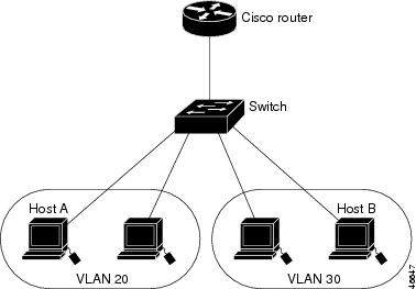
With a standard Layer 2 switch, ports in different VLANs have to exchange information through a router.
The switch supports these interface types:
Physical ports: switch ports and routed ports
VLANs: switch virtual interfaces
Port channels: EtherChannel interfaces
You can also configure a range of interfaces.
To configure a physical interface (port), specify the interface type, module number, and port number, and enter interface configuration mode.
Type: Gigabit Ethernet (gigabitethernet or gi) for 10/100/1000 Mb/s Ethernet ports,, or small form-factor pluggable (SFP) module Gigabit Ethernet interfaces (gigabitethernet or gi).
Module number: The module or slot number on the switch (always 0).
Port number: The interface number on the switch. The 10/100/1000 port numbers always begin at 1, starting with the far left port when facing the front of the switch, for example, gigabitethernet1/0/1 or gigabitethernet1/0/8. For a switch with 10/100/1000 ports and SFP module ports, SFP module ports are numbered consecutively following the 10/100/1000 ports.
You can identify physical interfaces by physically checking the interface location on the switch. You can also use the show privileged EXEC commands to display information about a specific interface or all the interfaces on the switch. The remainder of this chapter primarily provides physical interface configuration procedures.
This table shows the Ethernet interface default configuration, including some features that apply only to Layer 2 interfaces.
|
Feature |
Default Setting |
||
|---|---|---|---|
|
Operating mode |
Layer 2 or switching mode (switchport command). |
||
|
Allowed VLAN range |
VLANs 1– 4094. |
||
|
Default VLAN (for access ports) |
VLAN 1. |
||
|
Native VLAN (for IEEE 802.1Q trunks) |
VLAN 1. |
||
|
802.1p priority-tagged traffic |
Drop all packets tagged with VLAN 0. |
||
|
VLAN trunking |
Switchport mode dynamic auto (supports DTP). |
||
|
Port enable state |
All ports are enabled. |
||
|
Port description |
None defined. |
||
|
Speed |
Autonegotiate. (Not supported on the 10-Gigabit interfaces.) |
||
|
Duplex mode |
Autonegotiate. (Not supported on the 10-Gigabit interfaces.) |
||
|
Flow control |
Flow control is set to receive: off . It is always off for sent packets. |
||
|
EtherChannel (PAgP) |
Disabled on all Ethernet ports. |
||
|
Port blocking (unknown multicast and unknown unicast traffic) |
Disabled (not blocked). |
||
|
Broadcast, multicast, and unicast storm control |
Disabled. |
||
|
Protected port |
Disabled. |
||
|
Port security |
Disabled. |
||
|
Port Fast |
Disabled. |
||
|
Auto-MDIX |
Enabled.
|
||
|
Power over Ethernet (PoE) |
Enabled (auto). |
||
|
Keepalive messages |
Disabled on SFP module ports; enabled on all other ports. |
Ethernet interfaces on the switch operate at 10, 100, or 1000 Mb/s and in either full- or half-duplex mode. In full-duplex mode, two stations can send and receive traffic at the same time. Normally, 10-Mb/s ports operate in half-duplex mode, which means that stations can either receive or send traffic.
Switch modules include Gigabit Ethernet (10/100/1000-Mb/s) ports and small form-factor pluggable (SFP) module slots supporting SFP modules.
When configuring an interface speed and duplex mode, note these guidelines:
Do not disable Auto-Negotiation on PoE switches.
Gigabit Ethernet (10/100/1000-Mb/s) ports support all speed options and all duplex options (auto, half, and full). However, Gigabit Ethernet ports operating at 1000 Mb/s do not support half-duplex mode.
For SFP module ports, the duplex CLI options change depending on the SFP module type. Speeds of 10/100 Mb/s are not supported.
If both ends of the line support autonegotiation, we highly recommend the default setting of auto negotiation.
If one interface supports autonegotiation and the other end does not, configure duplex and speed on both interfaces; do not use the auto setting on the supported side.
When STP is enabled and a port is reconfigured, the switch can take up to 30 seconds to check for loops. The port LED is amber while STP reconfigures.
As best practice, we suggest configuring the speed and duplex options on a link to auto or to fixed on both the ends. If one side of the link is configured to auto and the other side is configured to fixed, the link will not be up and this is expected.
 Caution |
Changing the interface speed and duplex mode configuration might shut down and re-enable the interface during the reconfiguration. |
Flow control enables connected Ethernet ports to control traffic rates during congestion by allowing congested nodes to pause link operation at the other end. If one port experiences congestion and cannot receive any more traffic, it notifies the other port by sending a pause frame to stop sending until the condition clears. Upon receipt of a pause frame, the sending device stops sending any data packets, which prevents any loss of data packets during the congestion period.
Note |
The switch ports can receive, but not send, pause frames. |
Use the flowcontrol interface configuration command to set the interface’s ability to receive pause frames to on , off , or desired . The default state is on .
When set to desired , an interface can operate with an attached device that is required to send flow-control packets or with an attached device that is not required to but can send flow-control packets.
These rules apply to flow control settings on the device:
receive on (or desired ): The port cannot send pause frames but can operate with an attached device that is required to or can send pause frames; the port can receive pause frames.
receive off : Flow control does not operate in either direction. In case of congestion, no indication is given to the link partner, and no pause frames are sent or received by either device.
Note |
For details on the command settings and the resulting flow control resolution on local and remote ports, see the flowcontrol interface configuration command in the command reference for this release. |
These general instructions apply to all interface configuration processes.
| Command or Action | Purpose | |||
|---|---|---|---|---|
| Step 1 |
enable Example: |
Enables privileged EXEC mode.
|
||
| Step 2 |
configure terminal Example: |
Enters global configuration mode. |
||
| Step 3 |
interface Example: |
Identifies the interface type and the number of the connector.
|
||
| Step 4 |
Follow each interface command with the interface configuration commands that the interface requires. |
Defines the protocols and applications that will run on the interface. The commands are collected and applied to the interface when you enter another interface command or enter end to return to privileged EXEC mode. |
||
| Step 5 |
interface range or interface range macro |
(Optional) Configures a range of interfaces.
|
||
| Step 6 |
show interfaces |
Displays a list of all interfaces on or configured for the switch. A report is provided for each interface that the device supports or for the specified interface. |
| Command or Action | Purpose | |
|---|---|---|
| Step 1 |
enable Example: |
Enables privileged EXEC mode.
|
| Step 2 |
configure terminal Example: |
Enters global configuration mode. |
| Step 3 |
interface interface-id Example: |
Specifies the interface for which you are adding a description, and enter interface configuration mode. |
| Step 4 |
description string Example: |
Adds a description (up to 240 characters) for an interface. |
| Step 5 |
end Example: |
Returns to privileged EXEC mode. |
| Step 6 |
show interfaces interface-id description |
Verifies your entry. |
| Step 7 |
copy running-config startup-config Example: |
(Optional) Saves your entries in the configuration file. |
To configure multiple interfaces with the same configuration parameters, use the interface range global configuration command. When you enter the interface-range configuration mode, all command parameters that you enter are attributed to all interfaces within that range until you exit this mode.
| Command or Action | Purpose | |||
|---|---|---|---|---|
| Step 1 |
enable Example: |
Enables privileged EXEC mode.
|
||
| Step 2 |
configure terminal Example: |
Enters global configuration mode. |
||
| Step 3 |
interface range {port-range | macro macro_name} Example: |
Specifies the range of interfaces (VLANs or physical ports) to be configured, and enter interface-range configuration mode.
|
||
| Step 4 |
end Example: |
Returns to privileged EXEC mode. |
||
| Step 5 |
show interfaces [interface-id] Example: |
Verifies the configuration of the interfaces in the range. |
||
| Step 6 |
copy running-config startup-config Example: |
(Optional) Saves your entries in the configuration file. |
You can create an interface range macro to automatically select a range of interfaces for configuration. Before you can use the macro keyword in the interface range macro global configuration command string, you must use the define interface-range global configuration command to define the macro.
| Command or Action | Purpose | |||
|---|---|---|---|---|
| Step 1 |
enable Example: |
Enables privileged EXEC mode.
|
||
| Step 2 |
configure terminal Example: |
Enters global configuration mode. |
||
| Step 3 |
define interface-range macro_name interface-range Example: |
Defines the interface-range macro, and save it in NVRAM.
|
||
| Step 4 |
interface range macro macro_name Example: |
Selects the interface range to be configured using the values saved in the interface-range macro called macro_name . You can now use the normal configuration commands to apply the configuration to all interfaces in the defined macro. |
||
| Step 5 |
end Example: |
Returns to privileged EXEC mode. |
||
| Step 6 |
show running-config | include define Example: |
Shows the defined interface range macro configuration. |
||
| Step 7 |
copy running-config startup-config Example: |
(Optional) Saves your entries in the configuration file. |
| Command or Action | Purpose | |
|---|---|---|
| Step 1 |
enable Example: |
Enables privileged EXEC mode.
|
| Step 2 |
configure terminal Example: |
Enters global configuration mode. |
| Step 3 |
interface interface-id Example: |
Specifies the interface for which you are adding a description, and enter interface configuration mode. |
| Step 4 |
speed {10 | 100 | 1000} Example: |
Enter the appropriate speed parameter for the interface:
|
| Step 5 |
duplex {auto | full | half} Example: |
This command is not available on a 10-Gigabit Ethernet interface. Enter the duplex parameter for the interface. Enable half-duplex mode (for interfaces operating only at 10 or 100 Mb/s). You cannot configure half-duplex mode for interfaces operating at 1000 Mb/s. You can configure the duplex setting when the speed is set to auto . |
| Step 6 |
end Example: |
Returns to privileged EXEC mode. |
| Step 7 |
show interfaces interface-id Example: |
Displays the interface speed and duplex mode configuration. |
| Step 8 |
copy running-config startup-config Example: |
(Optional) Saves your entries in the configuration file. |
| Command or Action | Purpose | |
|---|---|---|
| Step 1 |
enable Example: |
Enables privileged EXEC mode.
|
| Step 2 |
configure terminal Example: |
Enters global configuration mode. |
| Step 3 |
interface interface-id Example: |
Specifies the interface for which you are adding a description, and enter interface configuration mode. |
| Step 4 |
flowcontrol {receive} {on | off | desired} Example: |
Configures the flow control mode for the port. |
| Step 5 |
end Example: |
Returns to privileged EXEC mode. |
| Step 6 |
show interfaces interface-id Example: |
Verifies the interface flow control settings. |
| Step 7 |
copy running-config startup-config Example: |
(Optional) Saves your entries in the configuration file. |
Shutting down an interface disables all functions on the specified interface and marks the interface as unavailable on all monitoring command displays. This information is communicated to other network servers through all dynamic routing protocols. The interface is not mentioned in any routing updates.
| Command or Action | Purpose | |
|---|---|---|
| Step 1 |
enable Example: |
Enables privileged EXEC mode.
|
| Step 2 |
configure terminal Example: |
Enters global configuration mode. |
| Step 3 |
interface {vlan vlan-id} | {gigabitethernet interface-id} | {port-channel port-channel-number} Example: |
Selects the interface to be configured. |
| Step 4 |
shutdown Example: |
Shuts down an interface. |
| Step 5 |
no shutdown Example: |
Restarts an interface. |
| Step 6 |
end Example: |
Returns to privileged EXEC mode. |
| Step 7 |
show running-config Example: |
Verifies your entries. |
Follow these steps to set the console media type to RJ-45. If you configure the console as RJ-45, USB console operation is disabled, and input comes only through the RJ-45 connector.
| Command or Action | Purpose | |
|---|---|---|
| Step 1 |
enable Example: |
Enables privileged EXEC mode.
|
| Step 2 |
configure terminal Example: |
Enters global configuration mode. |
| Step 3 |
line console 0 Example: |
Configures the console and enters line configuration mode. |
| Step 4 |
media-type rj45 Example: |
Configures the console media type to be only RJ-45 port. If you do not enter this command and both types are connected, the USB port is used by default. |
| Step 5 |
end Example: |
Returns to privileged EXEC mode. |
| Step 6 |
copy running-config startup-config Example: |
(Optional) Saves your entries in the configuration file. |
The configurable inactivity timeout reactivates the RJ-45 console port if the USB console port is activated but no input activity occurs on it for a specified time period. When the USB console port is deactivated due to a timeout, you can restore its operation by disconnecting and reconnecting the USB cable.
Note |
This procedure is not applicable to Cisco Catalyst 1000 Fast Ethernet Series Switches. |
| Command or Action | Purpose | |
|---|---|---|
| Step 1 |
enable Example: |
Enables privileged EXEC mode.
|
| Step 2 |
configure terminal Example: |
Enters global configuration mode. |
| Step 3 |
line console 0 Example: |
Configures the console and enters line configuration mode. |
| Step 4 |
usb-inactivity-timeout timeout-minutes Example: |
Specify an inactivity timeout for the console port. The range is 1 to 240 minutes. The default is to have no timeout configured. |
| Step 5 |
copy running-config startup-config Example: |
(Optional) Saves your entries in the configuration file. |
Commands entered at the privileged EXEC prompt display information about the interface, including the versions of the software and the hardware, the configuration, and statistics about the interfaces.
|
Command |
Purpose |
|---|---|
|
show interfaces interface-number downshift modulemodule-number |
Displays the downshift status details of the specified interfaces and modules. |
|
show interfaces interface-id status [err-disabled] |
Displays interface status or a list of interfaces in the error-disabled state. |
|
show interfaces [interface-id] switchport |
Displays administrative and operational status of switching (nonrouting) ports. You can use this command to find out if a port is in routing or in switching mode. |
|
show interfaces [interface-id] description |
Displays the description configured on an interface or all interfaces and the interface status. |
|
show ip interface [interface-id] |
Displays the usability status of all interfaces configured for IP routing or the specified interface. |
|
show interface [interface-id] stats |
Displays the input and output packets by the switching path for the interface. |
|
show interfaces interface-id |
(Optional) Displays speed and duplex on the interface. |
|
show interfaces transceiver dom-supported-list |
(Optional) Displays Digital Optical Monitoring (DOM) status on the connect SFP modules. |
|
show interfaces transceiver properties |
(Optional) Displays temperature, voltage, or amount of current on the interface. |
|
show interfaces [interface-id] [{transceiver properties | detail}] module number] |
Displays physical and operational status about an SFP module. |
|
show running-config interface [interface-id] |
Displays the running configuration in RAM for the interface. |
|
show version |
Displays the hardware configuration, software version, the names and sources of configuration files, and the boot images. |
|
show controllers ethernet-controller interface-id phy |
Displays the operational state of the auto-MDIX feature on the interface. |
|
Command |
Purpose |
|---|---|
|
clear counters [interface-id] |
Clears interface counters. |
|
clear interface interface-id |
Resets the hardware logic on an interface. |
|
clear line [number | console 0 | vty number] |
Resets the hardware logic on an asynchronous serial line. |
Note |
The clear counters privileged EXEC command does not clear counters retrieved by using Simple Network Management Protocol (SNMP), but only those seen with the show interface privileged EXEC command. |
This example shows how to use the interface range global configuration command to set the speed to 100 Mb/s on ports 1 to 4 on switch 1:
Device# configure terminal
Device(config)# interface range gigabitethernet 1/0/1 - 4
Device(config-if-range)# speed 100
If you enter multiple configuration commands while you are in interface-range mode, each command is executed as it is entered. The commands are not batched and executed after you exit interface-range mode. If you exit interface-range configuration mode while the commands are being executed, some commands might not be executed on all interfaces in the range. Wait until the command prompt reappears before exiting interface-range configuration mode.
This example shows how to define an interface-range named enet_list to include ports 1 and 2 on switch 1 and to verify the macro configuration:
Device# configure terminal
Device(config)# define interface-range enet_list gigabitethernet 1/0/1 - 2
Device(config)# end
Device# show running-config | include define
define interface-range enet_list gigabitethernet 1/0/1 - 2
This example shows how to enter interface-range configuration mode for the interface-range macro enet_list:
Device# configure terminal
Device(config)# interface range macro enet_list
Device(config-if-range)#
This example shows how to delete the interface-range macro enet_list and to verify that it was deleted.
Device# configure terminal
Device(config)# no define interface-range enet_list
Device(config)# end
Device# show run | include define
Device#
This example shows how to set the interface speed to 100 Mb/s and the duplex mode to half on a 10/100/1000 Mb/s port:
Device# configure terminal
Device(config)# interface gigabitethernet 1/0/3
Device(config-if)# speed 10
Device(config-if)# duplex half
This example shows how to set the interface speed to 100 Mb/s on a 10/100/1000 Mb/s port:
Device# configure terminal
Device(config)# interface gigabitethernet 1/0/2
Device(config-if)# speed 100This example disables the USB console media type and enables the RJ-45 console media type.
Device# configure terminal
Device(config)# line console 0
Device(config-line)# media-type rj45
This example reverses the previous configuration and immediately activates any USB console that is connected.
Device# configure terminal
Device(config)# line console 0
Device(config-line)# no media-type rj45
This example configures the inactivity timeout to 30 minutes:
Device# configure terminal
Device(config)# line console 0
Device(config-line)# usb-inactivity-timeout 30
To disable the configuration, use these commands:
Device# configure terminal
Device(config)# line console 0
Device(config-line)# no usb-inactivity-timeout
If there is no (input) activity on a USB console port for the configured number of minutes, the inactivity timeout setting applies to the RJ-45 port, and a log shows this occurrence:
*Mar 1 00:47:25.625: %USB_CONSOLE-6-INACTIVITY_DISABLE: Console media-type USB disabled due to inactivity, media-type reverted to RJ45.
At this point, the only way to reactivate the USB console port is to disconnect and reconnect the cable.
When the USB cable on the switch has been disconnected and reconnected, a log similar to this appears:
*Mar 1 00:48:28.640: %USB_CONSOLE-6-MEDIA_USB: Console media-type is USB.
The following table provides release information about the feature or features described in this module. This table lists only the software release that introduced support for a given feature in a given software release train. Unless noted otherwise, subsequent releases of that software release train also support that feature.
Use Cisco Feature Navigator to find information about platform support and Cisco software image support. To access Cisco Feature Navigator, go to www.cisco.com/go/cfn. An account on Cisco.com is not required.|
Feature |
Release |
Feature Information |
|---|---|---|
|
Configuring Interface Characteristics |
This feature was introduced. |
 Feedback