Cisco IE 2000 IP67 Certified Switch Hardware Installation Guide
Bias-Free Language
The documentation set for this product strives to use bias-free language. For the purposes of this documentation set, bias-free is defined as language that does not imply discrimination based on age, disability, gender, racial identity, ethnic identity, sexual orientation, socioeconomic status, and intersectionality. Exceptions may be present in the documentation due to language that is hardcoded in the user interfaces of the product software, language used based on RFP documentation, or language that is used by a referenced third-party product. Learn more about how Cisco is using Inclusive Language.
- Updated:
- August 19, 2014
Chapter: Switch Installation
Switch Installation
This chapter describes how to install your switch, verify the boot fast, and connect the switch to other devices. It also includes information specifically for installations in hazardous environments.
We recommend performing a preliminary configuration of the switch before it is installed in a permanent location.
Preparing for Installation
Warnings
These warnings are translated into several languages in the Regulatory Compliance and Safety Information for this switch.

Warning Before working on equipment that is connected to power lines, remove jewelry (including rings, necklaces, and watches). Metal objects will heat up when connected to power and ground and can cause serious burns or weld the metal object to the terminals. Statement 43
Warning Do not work on the system or connect or disconnect cables during periods of lightning activity. Statement 1001
Warning Before performing any of the following procedures, ensure that power is removed from the DC circuit. Statement 1003
Warning Read the installation instructions before you connect the system to its power source. Statement 1004
Warning This unit is intended for installation in restricted access areas. A restricted access area can be accessed only through the use of a special tool, lock and key, or other means of security. Statement 1017
Warning This equipment must be grounded. Never defeat the ground conductor or operate the equipment in the absence of a suitably installed ground conductor. Contact the appropriate electrical inspection authority or an electrician if you are uncertain that suitable grounding is available. Statement 1024
Warning This unit might have more than one power supply connection. All connections must be removed to de-energize the unit. Statement 1028
Warning Only trained and qualified personnel should be allowed to install, replace, or service this equipment. Statement 1030
Warning Ultimate disposal of this product should be handled according to all national laws and regulations. Statement 1040
Warning For connections outside the building where the equipment is installed, the following ports must be connected through an approved network termination unit with integral circuit protection.
10/100/1000 Ethernet, Console, and Alarm Statement 1044
Warning To prevent the system from overheating, do not operate it in an area that exceeds the maximum recommended ambient temperature of:
140°F (60°C) Statement 1047
Warning Voltages that present a shock hazard may exist on Power over Ethernet (PoE) circuits if interconnections are made using uninsulated exposed metal contacts, conductors, or terminals. Avoid using such interconnection methods, unless the exposed metal parts are located within a restricted access location and users and service people who are authorized within the restricted access location are made aware of the hazard. A restricted access area can be accessed only through the use of a special tool, lock and key or other means of security. Statement 1072
Warning Installation of the equipment must comply with local and national electrical codes. Statement 1074

– Top and bottom: 2.0 in. (50.8 mm)
– Sides: 2.0 in. (50.8 mm)
– Front: 2.0 in. (50.8 mm)
EMC Environmental Conditions for Products Installed in the European Union
This section applies to products to be installed in the European Union.
The equipment is intended to operate under the following environmental conditions with respect to EMC:
- A separate defined location under the user’s control.
- Earthing and bonding shall meet the requirements of ETS 300 253 or CCITT K27.
- AC-power distribution shall be one of the following types, where applicable: TN-S and TN-C as defined in IEC 364-3.
In addition, if equipment is operated in a domestic environment, interference could occur.
Environment and Enclosure Guidelines
Review these environmental and enclosure guidelines before installation:
- This equipment is considered Group 1, Class A industrial equipment, according to IEC/CISPR Publication 11. Without appropriate precautions, there may be potential difficulties ensuring electromagnetic compatibility in other environments due to conducted as well as radiated disturbance.
General Guidelines
Before installation, observe these general guidelines:
Do not touch connectors or pins on component boards. Do not touch circuit components inside the switch. When not in use, store the equipment in appropriate static-safe packaging.
- If you are responsible for the application of safety-related programmable electronic systems (PES), you need to be aware of the safety requirements in the application of the system and be trained in using the system.
When determining where to place the switch, observe these guidelines:
- Before installing the switch, first verify that the switch is operational by powering it on and observing boot fast. Follow the procedures in the “Where to Go Next” section.
- For 10/100 ports and 10/100/1000 ports, the cable length from a switch to an attached device cannot exceed 328 feet (100 meters).
- Operating environment is within the ranges listed in Appendix F, “Technical Specifications.”
- Clearance to front and rear panels meets these conditions:
– Front-panel LEDs can be easily read.
– Access to ports is sufficient for unrestricted cabling.
– Front-panel direct current (DC) power connectors and the alarm connector are within reach of the connection to the DC power source.
- Airflow around the switch must be unrestricted. To prevent the switch from overheating, you must have the following minimum clearances:
Verifying Package Contents
Included in the box is the switch itself and it’s installation documentation. If any item is missing or damaged, contact your representative or reseller for support.
Tools and Equipment
Obtain these necessary tools and equipment:
- A single or a pair of stud size 6 ring terminals (Hollingsworth part number R3456B or equivalent) for use as a protective ground connector.
- Crimping tool (Thomas & Bett part number WT2000, ERG-2001 or equivalent).
- 10-gauge copper ground wire.
- UL- and CSA-rated, style 1007 or 1569 twisted-pair copper appliance wiring material (AWM) wire for DC power connections.
- Wire-stripping tools for stripping 10-, 16-, and 18-gauge wires.
- Number-2 Phillips screwdriver.
- Flat-blade screwdriver.
- 15mm 12pt socket for IP67 dust caps
- Torque Driver (Such as a Torqueleader TT500 or equivalent)
Installing or Removing the Memory Card (Optional)
The switch supports a hot-swappable SD memory card (SD-IE-1GB) firmware and the startup configuration are stored, making it possible to replace a failed switch without reconfiguring the replacement switch.
The SD memory card cover protects the flash card against shock and vibration by holding the card in place. The cover is hinged and secured with captive screws. The slot for the SD memory card is located on the side of the switch.
To install or replace the SD memory card, follow these steps:
Step 1 On the side of the switch, loosen the captive screws until they are free of the chassis. See Figure 2-1.
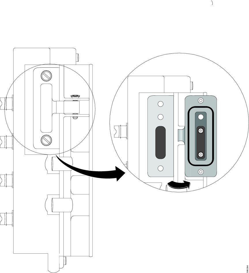
Step 2 Install or remove the card:
- To remove the card, push it in until it releases for it to pop out. Place it in an antistatic bag to protect it from static discharge.
- To install a card, slide it into the slot, and press on it until it clicks in place. The card is keyed so that you cannot insert it the wrong way.
Step 3 Close the guard door and fasten the captive screws to 15.93 to 19.47 in/lbs (1.8 -2.2Nm) to maintain IP67 compliance.
Connecting a PC or Terminal to the Console Port
To configure the device, you can connect a PC or terminal to the console port and enter Cisco IOS commands through the CLI. This section describes the procedure for connecting a PC to the console port and using a terminal emulator application, such as Hyperterminal, to configure the device.
Step 1 Connect the 5-pole-to-DB-9 adapter cable to a 9-pin serial port on a PC. Connect the other end of the cable to the switch console port.
Step 2 Start a terminal-emulation program on the PC or the terminal. The program, frequently a PC application such as HyperTerminal, makes communication between the switch and your PC or terminal possible.
Step 3 Configure the baud rate and character format of the PC or terminal to match the console port characteristics:
Step 4 Connect power to the switch as described in Connecting to Power.
Step 5 The PC or terminal displays the bootloader sequence. Press Enter to display the setup prompt. Follow the steps in the “Completing the Setup Program” section.
Step 6 To ensure IP67 compliance, make sure all console dust caps and cables are in place and torqued to 4.43 to 7.08 in/lbs (0.5 to 0.8 Nm).
Connecting to Power
You must supply a power solution for the device. PoE power is drawn from the single power connection; there is no separate power input for 44-57V (e.g.: with 24V input) for PoE. You must provide 44-57V input for PoE capability and 50-57V input for PoE+ capability.
If POE operation is not used, the input voltage should be between 12V and 60Vdc
Figure 2-2 Cisco IP67 160W Power Supply (optional)
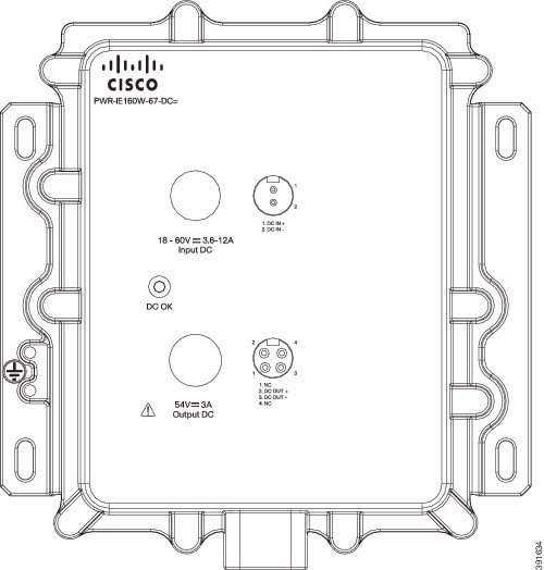
If a Cisco IP67 DC/DC PoE power supply is used (See Figure 2-2) to supply power to the switch, connect the female end of circular mini-change cable to the power connector on the switch and male end to the PoE power supply. The recommended Molex part number for the 1 meter IP67 cable is 1300100864.

Note The recommended length for the IP67 output cable is 1 meter.
If a custom power supply is used, use the power cable with pig tail ends. Connect the female end of the circular mini-change cable to the power connector on the switch (torque = 10in/lbs) and connect the pigtail to the non-standard power supply.
The open / pigtail end has four wires for feeds A and B. Connect the wires from A+ and A- to the positive and negative terminals of custom power supply. If redundancy is needed, connect the wires from B+ and B- to the positive and negative terminals of the second power supply. If redundancy is not needed, the terminal B+ and B- should not be connected to the A+ and A- terminals respectively. The recommended torque to achieve IP67 compliance is 10 in-lbs (1.13 Nm) for the power input connector on the switch, power output and input connector on the Cisco IP67 power supply.
Grounding the Switch
Follow any grounding requirements at your site.
Warning This equipment is intended to be grounded to comply with emission and immunity requirements. Ensure that the switch functional ground lug is connected to earth ground during normal use. Statement 1064
A ground lug is not supplied with the switch. You can select from these options:
To ground the switch to earth ground by using the ground screw, follow these steps:
Step 1 Use a standard Phillips screwdriver or a ratcheting torque screwdriver with a Phillips head to remove the ground screw from the switch. Store the ground screw for later use.
Step 2 Use the manufacturer guidelines to determine the wire length to be stripped.
Step 3 Insert the ground wire into the ring terminal lug, and using a crimping tool, crimp the terminal to the wire. See Figure 2-3. If two ring terminals are being used, repeat this action for a second ring terminal.
Figure 2-3 Crimping the Ring Terminal

Step 4 Slide the ground screw through the terminal.
Step 5 Insert the ground screw into the ground screw opening.
Step 6 Use a ratcheting torque screwdriver to tighten the ground screws and ring terminal to the switch front panel to 3.5 in-lb (0.4 N-m). The torque must not exceed 3.5 in-lb (0.4 N-m).
Step 7 Attach the other end of the ground wire to a grounded, bare metal surface, such as a ground bus, a grounded DIN rail, or a grounded bare rack.
Connecting the earth ground wire
Step 1 Measure a single length of stranded copper wire long enough to connect the power supply to the earth ground. The wire color might differ depending on the country that you are using it in.
Note For connections from the power supply to earth ground, use 10 to 12-AWG stranded copper wire.
Step 2 Connect one end of the stranded copper wire to a grounded bare metal surface, such as a ground bus, a grounded DIN rail, or a grounded bare rack.
Connect the other end of the wire to the grounding screw on the power supply. Only wire with insulation should extend from the connection.
Note The position of the power supply may vary on different switch models.
Step 3 Tighten the earth-ground wire connection screw.
Note Torque to 8 in.-lb, not to exceed 10 in-lb.
Running Boot Fast
When the switch powers on, it automatically initiates a boot fast sequence. The boot fast sequence allows the switch to boot up in less than 60 seconds.
When you power on the switch, it automatically begins a boot fast sequence. The System LED blinks green as the Cisco iOS firmware image loads. If the boot fast sequence fails, the System LED turns red.
Note Boot fast failures are usually fatal. Call Cisco TAC if your switch does not complete boot fast successfully. See also the “Related Publications” section.
Note You can disable the boot fast and run POST by using the Cisco IOS CLI. See the Cisco IE 2000 Switch Software Configuration Guide and the Cisco IE 2000 Switch Command Reference for more information.
Running Express Setup
Use Express Setup to enter the initial IP management information. You can then access the switch through the IP address for additional configuration.
You need this equipment to set up the switch:
- PC with Windows 7, XP, 2000, Vista, or Windows Server 2003
- Web browser (Internet Explorer 6.0, 7.0, or Firefox 1.5, 2.0, 3.0) with JavaScript enabled
- Straight-through or crossover Category 5 or 6 cable
Note Before running Express Setup, disable any pop-up blockers or proxy settings on your browser and any wireless client running on your PC.
Step 1 Make sure that nothing is connected to the switch.
During Express Setup, the switch acts as a DHCP server. If your PC has a static IP address, write down the PC static IP address and temporarily configure your PC settings to use DHCP before going to the next step.
Step 2 Connect power to the switch.
See the instructions in the “Connecting to Power” section.
The boot fast sequence begins. This process can take up to 60 seconds. During boot fast, the SYS LED blinks green, and the other LEDs turn steady green. When boot fast is complete, the SYS LED turns steady green and the other LEDs turn off.
If the SYS LED is off (system not powered on), continues to blink green (POST in progress), or is solid red (Fault), contact the Cisco Technical Assistance Center (TAC).
Step 3 Press the Express Setup button (located next to the SD Card cover) for 2 to 3 seconds. This button is recessed behind the panel, so you can use a simple tool, such as a paper clip.
When you press the Express Setup button, a switch port LED begins blinking green.
Step 4 Connect a Category 5 Ethernet cable (not provided) from the blinking switch port to the Ethernet port on your PC.
The port LEDs on your PC and on the switch blink green while the switch configures the connection. The steady green port LEDs indicate a successful connection.
If the port LEDs do not turn green after about 30 seconds, make sure that:
Step 5 Start a browser session on the PC. A login prompt appears.
Step 6 Leave the username blank and enter the default password cisco .
The Express Setup window appears.
If the Express Setup window does not appear, make sure that any pop-up blockers or proxy settings on your browser are disabled and that any wireless client is disabled on your PC.
Step 7 Enter the following Network Settings parameters in English letters and Arabic numbers:
- Management Interface (VLAN) : We recommend using the default, VLAN 1 . The management VLAN establishes an IP connection to the switch. Enter a new VLAN ID only if you want to change the management interface through which you manage the switch. The VLAN ID range is 1 to 1001.
- IP Assignment Mode : We recommend using the default, Static , so that the switch always has the IP address that you assign. Use the DHCP setting when you want the switch to automatically obtain an IP address from a DHCP server.
- IP Address : Enter the IP address for the switch. You can later use the IP address to access the switch through Device Manager.
- Subnet Mask : Select a mask from the drop-down list.
- Default Gateway : Enter the IP address of the router.
- Switch Password : Enter a password. The password can be from 1 to 25 alphanumeric characters, can start with a number, is case sensitive, allows embedded spaces, but does not allow spaces at the beginning or end. In the Confirm Password field, enter the password again.
Note You must change the password from the default password, cisco.
Step 8 Enter the Control Industrial Protocol (CIP) VLAN settings:
- CIP VLAN : Enter the VLAN on which CIP will be enabled. The CIP VLAN can be the same as the management VLAN, or you can isolate CIP traffic on another VLAN that is already configured on the switch. The default CIP VLAN is VLAN 1. Only one VLAN on a switch can have CIP enabled.
- IP Address : Enter the IP address for the CIP VLAN. If the CIP VLAN is different from the management VLAN, you must specify an IP address for the CIP VLAN. Make sure that the IP address that you assign to the switch is not being used by another device in your network.
- Subnet Mask : Select a mask from the drop-down list.
For more information about the CIP VLAN settings, click Help on the toolbar.
Step 9 You can enter the optional information now or enter it later by using Device Manager. For more information about the Express Setup fields, see the online help for the Express Setup window.
For more information about the optional settings, click Help on the toolbar.
Step 10 Click Submit to save your changes and to complete the initial setup.
The switch is configured and exits Express Setup mode.
The browser displays a warning message and tries to connect with the earlier switch IP address. Typically, connectivity between the PC and the switch is lost because the configured switch IP address is in a different subnet from the IP address on the PC.
Step 11 Turn off power at the source, disconnect all cables to the switch, and physically install the switch in your network.
If you changed the static IP address on your PC in Step 1, change it to the previously configured static IP address.
You can now manage the switch by using the Cisco Network Assistant, Device Manager, or CLI.
Launching Device Manager
Display Device Manager by following these steps:
Step 1 Start a web browser on your PC or laptop.
Step 2 Enter the switch IP address, username, and password (assigned in Step 6) in the web browser, and press Enter . The Device Manager page appears.
If the Device Manager page does not appear:
- Confirm that the port LED for the switch port connected to your network is green.
- Confirm that the PC that you are using to access the switch has network connectivity by connecting it to a well known web server in your network. If there is no network connection, troubleshoot the network settings on the PC.
- Make sure that the switch IP address in the browser is correct.
- Configure a static IP address on the PC that is in the same subnetwork as the switch IP address.
- When the LED on the switch port connected to the PC or laptop is green, reenter the switch IP address in a web browser to display the Device Manager.
Connecting Alarm Circuits
After the switch is installed, you can connect the alarm.
For instructions on grounding the switch and connecting it to power, see the “Connecting to Power” section.
Wiring the External Alarms
Use M12 A-coded cable to connect to the alarm connector on the switch. Recommended torque is 4.43 to 7.08 in/lbs (0.5 to 0.8 Nm).
The recommended cable part number from Molex is 1200650523. One end of the cable has M12 A-coded connector and the other end is open.
The labels for the alarm connector are on the switch panel and are displayed in Table 2-1 .
Connecting Destination Ports
These section provides information about connecting to the destination ports.
Connecting to 10/100 and 10/100/1000 Ports
The switch 10/100/1000 ports automatically configure themselves to operate at the speed of attached devices. If the attached ports do not support autonegotiation, you can explicitly set the speed and duplex parameters. Connecting devices that do not autonegotiate or that have their speed and duplex parameters manually set can reduce performance or result in no linkage.
To maximize performance, choose one of these methods for configuring the Ethernet ports:
- Let the ports autonegotiate both speed and duplex.
- Set the port speed and duplex parameters on both ends of the connection.
The models that support PoE provide up to four ports of either PoE (15.4 W per port; IEEE 802.3af) or PoE+ (30 W per port; IEEE 802.3at), depending on the power source used. See Power Requirements.
To connect to 10BASE-T, 100BASE-TX or 1000BASE-T devices, follow these steps:
Step 1 When connecting to workstations, servers, routers, and Cisco IP phones, connect a straight-through cable to a M12 connector (IP67 Torque: 4.43 to 7.08 in/lbs or 0.5 to 0.8 Nm) on the front panel. See .
When connecting to 1000BASE-T-compatible devices, use a twisted four-pair, Category 5 or higher cable.
The auto-MDIX feature is enabled by default. For configuration information for this feature, see the Cisco IE 2000 Switch Software Configuration Guide or the Cisco IE 2000 Switch Command Reference .
Step 2 Connect the other end of the cable to a M12 connector on the other device. The port LED turns on when both the switch and the connected device have established a link.
The port LED is amber while Spanning Tree Protocol (STP) discovers the topology and searches for loops. This can take up to 30 seconds, and then the port LED turns green. If the port LED does not turn on:
- The device at the other end might not be turned on.
- There might be a cable problem or a problem with the adapter installed in the attached device. See “Troubleshooting,” for solutions to cabling problems.
Step 3 Reconfigure and reboot the connected device if necessary.
Step 4 Repeat Steps 1 through 3 to connect each device.
Step 5 To ensure IP67 compliance, make sure all alarm dust caps and cables are in place and torqued to 4.43 to 7.08 in/lbs (0.5 to 0.8 Nm).
Where to Go Next
If the default configuration is satisfactory, the switch does not need further configuration. You can use any of these management options to change the default configuration:
You can use Device Manager web interface to manage and monitor individual switches. Device Manager can be accessed from anywhere in your network through a web browser by using the management IP address of the switch. For more information, see the Device Manager online help.
The switch CLI is a version of Cisco iOS firmware that can be used to configure and monitor the switch. You can access the CLI either by connecting your management station directly to the switch console port or by using Telnet from a remote management station. See the Cisco IE 2000 Switch Command Reference on Cisco.com for more information.
Cisco Network Assistant is a PC-based network management GUI optimized for LANs used in small- and medium-sized businesses. Using this GUI, you can configure and manage switch clusters or standalone switches. Cisco Network Assistant is available at no cost and can be downloaded from:
http://www.cisco.com/en/US/products/ps5931/tsd_products_support_series_home.html
For more information on Cisco Network Assistant, see the Getting Started with Cisco Network Assistant guide on Cisco.com.
http://www.cisco.com/en/US/docs/net_mgmt/ciscoworks_lan_management_solution/4.2/device_support/table/lms42sdt.html#Cisco IE 2000 Series Switches
Switches can be managed by using a SNMP-compatible management station running platforms such as HP OpenView or SunNet Manager. The switch supports a comprehensive set of Management Information Base (MIB) extensions and four Remote Monitoring (RMON) groups. See the Cisco IE 2000 Switch Software Configuration Guide on Cisco.com and the documentation that came with your SNMP application for more information.
Common Industrial Protocol (CIP) management objects are supported by the switch, allowing you to manage an entire industrial automation system with one tool.
This switch supports PROFINET TCP/IP and RT, and can be managed by Siemens automation software such as STEP 7.
 Feedback