Redundancy Protocol Configuration Guide, Cisco Catalyst IE3x00 and IE3100 Rugged, IE3400 Heavy Duty, and ESS3300 Series Switches
Bias-Free Language
The documentation set for this product strives to use bias-free language. For the purposes of this documentation set, bias-free is defined as language that does not imply discrimination based on age, disability, gender, racial identity, ethnic identity, sexual orientation, socioeconomic status, and intersectionality. Exceptions may be present in the documentation due to language that is hardcoded in the user interfaces of the product software, language used based on RFP documentation, or language that is used by a referenced third-party product. Learn more about how Cisco is using Inclusive Language.
Your software release may not support all the features documented in this module. For the latest caveats and feature information,
see Bug Search Tool and the release notes for your platform and software release. To find information about the features documented
in this module, and to see a list of the releases in which each feature is supported, see the feature information table at
the end of this module.
Use Cisco Feature Navigator to find information about platform support and Cisco software image
support. To access Cisco Feature Navigator, go to https://cfn.cloudapps.cisco.com/ITDIT/CFN/.
An account on Cisco.com is not required.
Resilient Ethernet Protocol Overview
Resilient Ethernet Protocol (REP) is a Cisco proprietary protocol that provides an alternative to Spanning Tree Protocol (STP)
to control network loops, handle link failures, and improve convergence time. REP controls a group of ports connected in a
segment, ensures that the segment does not create any bridging loops, and responds to link failures within the segment. REP
provides a basis for constructing more complex networks and supports VLAN load balancing.
Note
The feature is supported on Cisco Series Switches with the Network Essentials license.
Note
REP configuration on downlink ports is supported starting with Cisco IOS XE Fuji
16.9.1.
REP segment is a chain of ports connected to each other and configured with a segment ID. Each segment consists of standard
(non-edge) segment ports and two user-configured edge ports. A switch can have no more than two ports that belong to the same
segment, and each segment port can have only one external neighbor. A segment can go through a shared medium, but on any link,
only two ports can belong to the same segment. REP is supported only on Trunk ports.
The figure below shows an example of a segment consisting of six ports spread across four switches. Ports E1 and E2 are configured
as edge ports. When all ports are operational (as in the segment on the left), a single port is blocked, shown by the diagonal
line. This blocked port is also known as the Alternate port (ALT port). When there is a failure in the network, the blocked
port returns to the forwarding state to minimize network disruption.
Figure 1. REP Open Segment
The segment shown in the figure above is an open segment; there is no connectivity between the two edge ports. The REP segment
cannot cause a bridging loop, and you can safely connect the segment edges to any network. All hosts connected to switches
inside the segment have two possible connections to the rest of the network through the edge ports, but only one connection
is accessible at any time. If a failure occurs on any segment or on any port on a REP segment, REP unblocks the ALT port to
ensure that connectivity is available through the other gateway.
The segment below is a closed segment, also known as Ring Segment, with both edge ports located on the same router. With
this configuration, you can create a redundant connection between any two routers in the segment.
Figure 2. REP Ring Segment
REP segments have the following characteristics:
If all ports in a segment are operational, one port (referred to as the ALT port) is in the blocked state for each VLAN.
If VLAN load balancing is configured, two ALT ports in the segment control the blocked state of VLANs.
If a port is not operational, and cause a link failure, all ports forward traffic on all VLANs to ensure connectivity.
In case of a link failure, alternate ports are unblocked as quickly as possible. When the failed link is restored, a logically
blocked port per VLAN is selected with minimal disruption to the network.
You can construct almost any type of network based on REP segments.
In access ring topologies, the neighboring switch might not support REP as shown in the figure below. In this case, you can
configure the non-REP facing ports (E1 and E2) as edge no-neighbor ports. The edge no-neighbor port can be configured to send
an STP topology change notice (TCN) towards the aggregation switch.
Figure 3. Edge No-Neighbor Ports
REP has these limitations:
You must configure each segment port; an incorrect configuration can cause forwarding loops in the networks.
REP can manage only a single failed port within the segment; multiple port failures within the REP segment cause loss of network
connectivity.
You should configure REP only in networks with redundancy. Configuring REP in a network without redundancy causes loss of
connectivity.
Link Integrity
REP does not use an end-to-end polling function between edge ports to verify link integrity. It implements local link failure
detection. The REP Link Status Layer (LSL) detects its REP-aware neighbor and establishes connectivity within the segment.
All the VLANs are blocked on an interface until the neighbor is detected. After the neighbor is identified, REP determines
which neighbor port should become the alternate port and which ports should forward traffic.
Each port in a segment has a unique port ID. The port ID format is similar to that used by the spanning tree algorithm: a
port number (unique on the bridge) associated to a MAC address (unique in the network). When a segment port is coming up,
its LSL starts sending packets that include the segment ID and the port ID. The port is declared as operational after it performs
a three-way handshake with a neighbor in the same segment.
A segment port does not become operational if:
No neighbor has the same segment ID.
More than one neighbor has the same segment ID.
A neighbor does not acknowledge a local port as a peer.
Each port creates an adjacency with its immediate neighbor. After the neighbor adjacencies are created, the ports negotiate
with each other to determine the blocked port for the segment, which will function as the alternate port. All the other ports
become unblocked. By default, REP packets are sent to a bridge protocol data unit-class MAC address. The packets can also
be sent to a Cisco multicast address, which is used only to send blocked port advertisement (BPA) messages when there is a
failure in the segment. The packets are dropped by the devices not running REP.
Fast Convergence
REP runs on a physical link basis and not on a per-VLAN basis. Only one hello message is required for all the VLANs, and this
reduces the load on the protocol. We recommend that you create VLANs consistently on all the switches in a given segment and
configure the same allowed VLANs on the REP trunk ports. To avoid the delay introduced by relaying messages in software, REP
also allows some packets to be flooded to a regular multicast address. These messages operate at the hardware flood layer
(HFL) and are flooded to the entire network, not just the REP segment. Switches that do not belong to the segment treat them
as data traffic. You can control flooding of these messages by configuring an administrative VLAN for the entire domain or
for a particular segment.
VLAN Load Balancing
One edge port in the REP segment acts as the primary edge port; and another as the secondary edge port. It is the primary
edge port that always participates in VLAN load balancing in the segment. REP VLAN balancing is achieved by blocking some
VLANs at a configured alternate port and all the other VLANs at the primary edge port. When you configure VLAN load balancing,
you can specify the alternate port in one of three ways:
By entering the port ID of the interface. To identify the port ID of a port in the segment, enter the show interface rep detail interface configuration command for the port.
By entering the preferred keyword to select the port that you previously configured as the preferred alternate port with the rep segmentsegment-idpreferred interface configuration command.
By entering the neighbor offset number of a port in the segment, which identifies the downstream neighbor port of an edge
port. The neighbor offset number range is –256 to +256; a value of 0 is invalid. The primary edge port has an offset number
of 1; positive numbers above 1 identify downstream neighbors of the primary edge port. Negative numbers indicate the secondary
edge port (offset number -1) and its downstream neighbors.
Note
Configure offset numbers on the primary edge port by identifying a port’s downstream position from the primary (or secondary)
edge port. Never enter an offset value of 1 because that is the offset number of the primary edge port.
The following figure shows neighbor offset numbers for a segment, where E1 is the primary edge port and E2 is the secondary
edge port. The red numbers inside the ring are numbers offset from the primary edge port; the black numbers outside of the
ring show the offset numbers from the secondary edge port. Note that you can identify all the ports (except the primary edge
port) by either a positive offset number (downstream position from the primary edge port) or a negative offset number (downstream
position from the secondary edge port). If E2 became the primary edge port, its offset number would then be 1 and E1 would
be -1.
Figure 4. Neighbor Offset Numbers in a Segment
When the REP segment is complete, all the VLANs are blocked. When you configure VLAN load balancing, you must also configure
triggers in one of two ways:
Manually trigger VLAN load balancing at any time by entering the rep preempt segmentsegment-id privileged EXEC command on the switch that has the primary edge port.
Configure a preempt delay time by entering the rep preempt delayseconds interface configuration command. After a link failure and recovery, VLAN load balancing begins after the configured preemption
time period elapses. Note that the delay timer restarts if another port fails before the time has elapsed.
Note
When VLAN load balancing is configured, it does not start working until triggered by either manual intervention or a link
failure and recovery.
When VLAN load balancing is triggered, the primary edge port sends out a message to alert all the interfaces in the segment
about the preemption. When the secondary port receives the message, the message is sent to the network to notify the alternate
port to block the set of VLANs specified in the message and to notify the primary edge port to block the remaining VLANs.
You can also configure a particular port in the segment to block all the VLANs. Only the primary edge port initiates VLAN
load balancing, which is not possible if the segment is not terminated by an edge port on each end. The primary edge port
determines the local VLAN load-balancing configuration.
Reconfigure the primary edge port to reconfigure load balancing. When you change the load-balancing configuration, the primary
edge port waits for the rep preempt segment command or for the configured preempt delay period after a port failure and recovery, before executing the new configuration.
If you change an edge port to a regular segment port, the existing VLAN load-balancing status does not change. Configuring
a new edge port might cause a new topology configuration.
Spanning Tree Interaction
REP does not interact with STP, but it can coexist. A port that belongs to a segment is removed from spanning tree control
and STP BPDUs are not accepted or sent from segment ports. Therefore, STP cannot run on a segment.
To migrate from an STP ring configuration to REP segment configuration, begin by configuring a single port in the ring as
part of the segment and continue by configuring contiguous ports to minimize the number of segments. Each segment always contains
a blocked port, so multiple segments means multiple blocked ports and a potential loss of connectivity. When the segment has
been configured in both directions up to the location of the edge ports, you then configure the edge ports.
Resilient Ethernet Protocol (REP) Negotiated
Note
REP Negotiated works only on uplink ports.
REP and Spanning Tree Protocol (STP) are two different loop avoidance protocols. REP has certain advantages over STP in terms
of convergence time. REP can be configured to run in a ring topology in such a way that it can provide the redundant path
in case of a single link failure in the ring.
Cisco switches are STP enabled by default. If a switch that is STP enabled is inserted in an already running REP ring (for
addition of a new node or replacement of existing node) the following conditions apply:
The new switch will cause a break in the REP ring.
The new switch will not be able to communicate over the ring until it is configured to be part of the REP ring.
The REP Negotiated feature tries to solve these issues by negotiating the REP status with the peers. The following table
identifies when REP Negotiation events will trigger and the action to take. There are two events: both peers are negotiating,
and neither peer is negotiating.
SELF REP Negotiated
PEERS REP Negotiated
Event Triggered
Action
True
True
REPN
Configure REP
True
False
REPNN
Configure STP
False
X
REPNN
Remain in STP
This feature depends on 3 different protocols to get the required data and decide the correct configuration. The different
protocols involved, and their purpose is given below:
STP: By default, STP is enabled on all the ports on the Cisco Switch.
REP: The customer network is configured to form a REP ring to provide better convergence time and redundancy.
CiscoDiscoveryProtocol(CDP): The feature depends on user defined TLVs sent through CDP messages to negotiate the correct (STP or REP) configuration for
the interface.
REP Ports
REP segments consist of Failed, Open, or Alternate ports:
A port configured as a regular segment port starts as a failed port.
After the neighbor adjacencies are determined, the port transitions to alternate port state, blocking all the VLANs on the
interface. Blocked-port negotiations occur, and when the segment settles, one blocked port remains in the alternate role and
all the other ports become open ports.
When a failure occurs in a link, all the ports move to the Failed state. When the Alternate port receives the failure notification,
it changes to the Open state, forwarding all the VLANs.
A regular segment port converted to an edge port, or an edge port converted to a regular segment port, does not always result
in a topology change. If you convert an edge port into a regular segment port, VLAN load balancing is not implemented unless
it has been configured. For VLAN load balancing, you must configure two edge ports in the segment.
A segment port that is reconfigured as a spanning tree port restarts according to the spanning tree configuration. By default,
this is a designated blocking port. If PortFast is configured or if STP is disabled, the port goes into the forwarding state.
REP Fast Overview
The Resilient Ethernet Protocol (REP) Fast feature allows faster link failure detection and convergence on the switch copper
Gigabit Ethernet (GE) ports.
REP was originally designed for Fast Ethernet (FE 10/100) ports. Link down detection time on FE ports is 10 milliseconds (ms)
and convergence time is about 50 ms. On Fiber GE ports, link down time is 10 ms, but on GE copper interfaces, the link drop
detection and recovery times are between 750 ms and 350 ms. As a result, link loss and recovery can be detected a lot more
quickly on GE fiber interfaces than on corresponding copper interfaces. This in turn means that the convergence time for REP
is a lot higher when using GE copper interfaces.
To improve link down detection time, a beacon mechanism is implemented to trigger faster link failure detection (within 5-10
ms) when a REP interface is configured for REP Fast mode. The switch has two timers for each REP interface. The first timer
is triggered every 3 ms to transmit the beacon frame to the neighbor node. After successful transmission and reception of
the frame, both the timers are reset. If the packet is not received after the transmission, then the second timer is triggered
to check the reception within 10 ms. If the packet is not received, upon the timer expiry, a link down message is sent to
the switch.
REP Fast works on a per link basis. It does not impact the REP Protocol. REP Fast requires both ends of the link to support
REP Fast to work. REP Fast can be used on any interface link pair configured for REP, but it was created to solve an issue
on Gigabit copper links. REP Fast speeds up detection of the link failure on Gigabit copper interfaces.
A REP Ring can have a mix of normal REP links and links with REP Fast. Interfaces with REP Fast will transmit 3000 packets
a second as part normal operation. REP Fast enablement does not impact REP ring size since it operates only on the pair of
interfaces configured for it. Because REP Fast has to generate Beacon frames, only six interfaces on a single REP node can
be configured for REP Fast at a time.
If the neighbor acknowledges and is configured for REP Fast mode, convergence occurs within 50 ms. If a neighbor switch does
not support the REP Fast feature, normal REP mode must be used for link up/down detection. In this case, you need to disable
fast mode on both ends of the link.
Before a network device such as a router or a switch is deployed online and fully functional, a fair amount of manual configuration
is required. Zero Touch Provisioning (ZTP) technologies automate these processes, bringing up network devices into a functional
state with minimal to no manual configuration. The Cisco Network Plug and Play (PnP) and Autoinstall Day Zero solutions provide
a simple, secure, unified, and integrated offering for enterprise and industrial network customers to ease device rollouts
for provisioning updates to an existing network. However, PnP does not support Resilient Ethernet Protocol (REP) due to the
way REP is designed. Prior to the REP ZTP feature, REP ring provisioning for Day Zero required manual intervention. The REP
ZTP feature introduces a new type-length-value (TLV) extension into the REP LSL packets to support configuring REP rings with
zero-touch technologies.
REP and Day Zero
In a typical switch deployment using ZTP, the switch, with no startup configuration in the NVRAM, triggers the Cisco Open
Plug-n-Play (PnP) agent to initiate a DHCP discovery process. This process acquires the IP configuration required for the
switch from the DHCP server. The DHCP server can be configured to insert additional information in a DHCP message using vendor
specific option 43. After the DHCP server receives a DHCP DISCOVER message with option 60 and the string "cisco pnp" from
the switch, the DHCP server sends the IP address or hostname of the PnP server to the requesting switch. When the switch receives
the DHCP response, the PnP agent extracts the option 43 from the response to get the IP address or the hostname of the PnP
server. The PnP agent on the switch then uses this IP address or hostname to communicate with the PnP server. Finally, the
PnP server downloads the required Day Zero configuration to the switch to complete the provisioning.
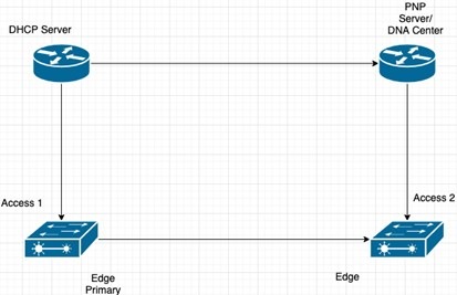
The example shown in the following diagrams illustrates REP ring provisioning on Day Zero, prior to the introduction of REP
ZTP.
Figure 5. Adding Edge Nodes to the REP Ring
Note
The DHCP Server and the PnP Server/DNA Center are not part of the REP ring.
The first set of nodes to be provisioned are Access 1 and Access 2 in the diagram. These are the 2 edge nodes of the REP ring.
Note that PnP has configured the downlink port as primary edge on Access 1 and secondary edge on Access 2.
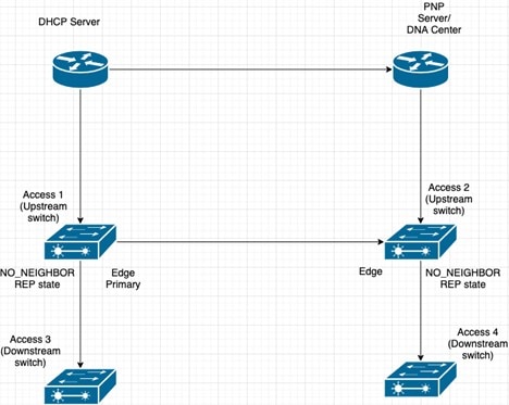
Figure 6. Adding Downstream Nodes
When either Access 3 or Access 4 are powered on, the REP edge primary port starts the REP protocol negotiation and discovers
that the neighbor port is not a REP enabled port. (Recall that the switch will be added to the REP ring only after PnP provisioning,
for which it needs to first contact the DHCP server as explained earlier.) When an upstream switch port has REP configured
and a downstream switch is getting on-boarded with PnP, the REP port goes into the NO_NEIGHBOR state because it is not able
to discover its REP peer. In the NO_NEIGHBOR state, REP blocks all the VLANs on that port. This means that the DHCP discovery
message from the new switch on the PnP startup VLAN is dropped by the upstream switch because its REP state is NO_NEIGHBOR.
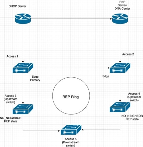
The same sequence of blocked ports continues for all new switches added to the REP ring (see Access 5 in figure below).
Figure 7. NO_NEIGHBOR REP State
REP ZTP Overview
The REP ZTP enhancements require that both the upstream and the downstream switches support the feature. When the new downstream
switch is powered on, it initiates PNP/autoinstall. The upstream switch's interface is configured for REP and blocks the interface
to the downstream switch because the downstream switch is not REP by default (the upstream switch is in REP_NO_NEIGHBOR state).
Even though the interface on the upstream switch is blocked, it will transmit REP LSL packets to the downstream switch. This
is normal. With the enhancement of the REP ZTP feature, the downstream switch will start transmitting REP LSL packets with
a new TLV to inform the upstream switch that its neighbor is attempting PNP provisioning.
When the upstream switch reads this REP LSL with the new TLV, it will unblock the interface for the PNP startup VLAN only.
All other VLANs for which the upstream interface is a member continue to be blocked. Because the upstream switch is forwarding
packets on the PNP startup VLAN for this interface, the downstream switch can complete the PNP process.
The intent of this feature is to allow new switches to join a REP ring with no manual intervention. The interface on the upstream
switch keeps the startup VLAN unblocked until the downstream switch has received its configuration and has configured its
own interface for REP. If there's a failure in the PNP proccess, the interface on the upstream switch reverts to blocking
on the PNP startup VLAN. If the configuration received by the downstream switch does configure the interface for REP, the
upstream switch reverts to blocking the PNP startup VLAN.
The downstream behavior to transmit the REP LSL with new TLV to request the PnP startup VLAN be unblocked is the default behavior
for switches with no startup configuration. For security purposes, the upstream switch must have the interface to the downstream
switch explicitly enabled to put the PnP startup VLAN into unblocked state. The interface level command is rep ztp-enable. See Configuring REP ZTP.
Note
The upstream switch can be part of multiple REP rings and thereby connected to multiple downstream neighbours. The PnP startup
VLAN is unblocked only on the interfaces to which the downstream switch is connected.
REP Segment-ID Autodiscovery
Resilient Ethernet Protocol (REP) Segment-ID Autodiscovery enables automatic configuration and continued static configuration
of segment IDs in REP segments. The feature is supported on Cisco Catalyst IE3x00 Rugged, IE3400 Heavy Duty, and ESS3300 Series
Switches beginning with the Cisco IOS XE Cupertino 17.9.x release.
A REP segment is a chain of ports that are connected to each other and configured with a segment ID. Forming multiple REP
segments statically by configuring each port of the device is a manual task, and any mismatch in configuring the segment ID
leads to convergence issues. However, REP Segment-ID Autodiscovery adds new CLI commands to enable a switch to learn and retain
segment ID information automatically.
You can use REP Segment-ID Autodiscovery in several different scenarios. You can insert a new switch into an existing REP
segment or in a new REP segment that you build yourself. The feature is ideal for multiple REP ring deployments when incorrect
REP Segment IDs might be entered manually. Such errors can occur when deploying multiple REP rings from the same REP seed
node.
See the following sections in this guide for more information:
You can configure REP Segment-ID Autodiscovery when you add a switch to a REP segment or when you create a REP segment. In
either case, the feature reduces the amount of manual configuration that you must do.
Adding a new Switch to an REP Segment
When you add a switch to an existing REP segment, you enable autodiscovery by entering the rep autodisc command on the switch interfaces connecting to the upstream and downstream switches.
When the new switch is connected to the upstream and downstream switches, the upstream and downstream switches send CDP packets
with REP segment ID information to the new switch interfaces. You enter the command rep segment auto on the new switch interfaces so they can learn the segment ID.
Building a new REP Segment
When you build a closed REP segment, you must start with a static REP segment ID configuration from an edge device. The primary
and secondary edge devices in a closed segment are on the same switch. When you build an open REP segment, you must start
a static REP segment ID configuration from both primary and secondary edge devices.
The remaining steps are the same for both closed and open REP segments. You bring up the next node in the REP ring. You then
add any next new node between these two switches for autodiscovery to work correctly.
Building a REP Segment with Uplinks
When you build a ring segment with uplinks (daisy chain), you must start with a static REP segment ID configuration from the
REP edge node. Connect the next device to one of the uplinks to the edge node, and enable autodiscovery on the connected uplink.
Because of port pairing support, the same REP configuration is duplicated on the paired uplink port.
When the next device is connected with the uplink, the process repeats to bring the REP segment in a daisy chain manner. Each
new REP node automatically joins the ring by learning the REP Segment ID from the node above it. For a REP open ring, the
last device on the segment is an edge device with static REP configuration.
REP Segment-ID Autodiscovery Limitations
The following are restrictions for the REP Segment-ID Autodiscovery feature:
The only supported port-pairing is uplinks Gi1/1 and Gi1/2. No predefined port pairing is supported for downlinks.
If you configure a REP segment on a downlink port, the switch receives the segment ID from the upstream switch, and the partner
downlink port is connected to the same segment. However, the switch does not pass the segment ID to its partner port. Instead,
you must explicitly configure the partner port of the downlink pair.
The REP Segment-ID Autodiscovery feature is not supported when you insert an edge node into the existing segment. You must
configure static or manual REP segment ID on primary and secondary edge devices.
If you insert a new switch between two switches that are part of a segment, you must connect the new switch interfaces to
the interfaces of existing switches that transmit the same segment ID. Any incorrect connections to other interfaces of the
existing switches leads to segment failure.
For example, assume gi1/1 of switch1 and gi1/2 of switch2 are connected as a part an existing segment, and switch3 is inserted
between these two switches. In such a case, you must ensure that the interfaces are connected to gi1/1 of switch1 and gi1/2
of switch2 to include switch3 as a part of the same segment.
If you configure REP automatically on an interface with the rep segment auto command, and you remove the REP configuration with the no rep segment command or overwrite it with the rep segment <> command, you cannot configure REP automatically again with the rep segment auto command. Instead, you must shut down the interface, bring it up, and then enter the rep segment auto command.
REP Segment ID Autodiscovery depends on the CDP protocol. The feature does not support EtherChannel links.
How to Configure Resilient Ethernet Protocol
A segment is a collection of ports connected to one another in a chain and configured with a segment ID. To configure REP
segments, configure the REP administrative VLAN (or use the default VLAN 1) and then add the ports to the segment, using interface
configuration mode. You should configure two edge ports in a segment, with one of them being the primary edge port and the
other the secondary edge port by default. A segment should have only one primary edge port. If you configure two ports in
a segment as primary edge ports, for example, ports on different switches, the REP selects one of them to serve as the segment's
primary edge port. If required, you can configure the location to which segment topology change notices (STCNs) and VLAN load
balancing are to be sent.
Default REP Configuration
REP is disabled on all the interfaces. When enabled, the interface is a regular segment port unless it is configured as an
edge port.
When REP is enabled, the task of sending segment topology change notices (STCNs) is disabled, all the VLANs are blocked, and
the administrative VLAN is VLAN 1.
When VLAN load balancing is enabled, the default is manual preemption with the delay timer disabled. If VLAN load balancing
is not configured, the default after manual preemption is to block all the VLANs in the primary edge port.
REP Fast is disabled by default.
REP Zero Touch Provisioning is enabled by default at the global level and disabled at the interface level.
REP Configuration Guidelines
Follow these guidelines when configuring REP:
We recommend that you begin by configuring one port and then configure contiguous ports to minimize the number of segments
and the number of blocked ports.
If more than two ports in a segment fail when no external neighbors are configured, one port goes into a forwarding state
for the data path to help maintain connectivity during configuration. In the showinterfacesrep command output, the Port Role for this port shows as “Fail Logical Open;” and the Port Role for the other failed port shows
as “Fail No Ext Neighbor.” When the external neighbors for the failed ports are configured, the ports go through the alternate
port state transitions and eventually go to an open state or remain as the alternate port, based on the alternate port selection
mechanism.
REP ports must be Layer 2 IEEE 802.1Q or Trunk ports.
We recommend that you configure all trunk ports in the segment with the same set of allowed VLANs.
Be careful when configuring REP through a Telnet connection. Because REP blocks all VLANs until another REP interface sends
a message to unblock it. You might lose connectivity to the router if you enable REP in a Telnet session that accesses the
router through the same interface.
You cannot run REP and STP on the same segment or interface.
If you connect an STP network to a REP segment, be sure that the connection is at the segment edge. An STP connection that
is not at the edge could cause a bridging loop because STP does not run on REP segments. All STP BPDUs are dropped at REP
interfaces.
If REP is enabled on two ports on a switch, both ports must be either regular segment ports or edge ports. REP ports follow
these rules:
There is no limit to the number of REP ports on a switch; however, only two ports on a switch can belong to the same REP segment.
If only one port on a switch is configured in a segment, the port should be an edge port.
If two ports on a switch belong to the same segment, they must be both edge ports, both regular segment ports, or one regular
port and one edge no-neighbor port. An edge port and regular segment port on a switch cannot belong to the same segment.
If two ports on a switch belong to the same segment and one is configured as an edge port and one as a regular segment port
(a misconfiguration), the edge port is treated as a regular segment port.
REP interfaces come up in a blocked state and remain in a blocked state until they are safe to be unblocked. You must be aware
of this status to avoid sudden connection losses.
REP sends all LSL PDUs in untagged frames on the native VLAN. The BPA message sent to the Cisco multicast address is sent
on the administration VLAN, which is VLAN 1 by default.
You can configure how long a REP interface remains up without receiving a hello from a neighbor. You can use the rep lsl-age-timer value interface configuration command to set the time from 120 ms to 10000 ms. The LSL hello timer is then set to the age-timer
value divided by 3. In normal operation, three LSL hellos are sent before the age timer on the peer switch expires and checks
for hello messages.
EtherChannel port channel interfaces do not support LSL age-timer values less than 1000 ms. If you try to configure a value
less than 1000 ms on a port channel, you receive an error message and the command is rejected.
lsl-age-timer is intended to be used when normal link down detection will be too slow for convergence time.
FastEthernet and fiber connections do not need lsl-age-timer. Gigabit copper can use REP Fast instead of lsl-age-timer.
You cannot configure REP ports as one of the following port types:
Switched Port Analyzer (SPAN) destination port
Tunnel port
Access port
REP is supported on EtherChannels, but not on an individual port that belongs to an EtherChannel.
There can be a maximum of 26 REP segments per switch.
There is no limit to the size of a REP ring. REP ring sizes greater than 20 nodes may not achieve sub 50ms convergence. The
use of REP ZTP or REP Segment ID Autodiscovery limits a single node to only three REP segments.
REP Fast
REP fastmode cannot co-exist with MACsec. This restriction applies to the IE3x00 Rugged, IE3400 Heavy Duty, and ESS3300 Series
Switches.
REP fastmode sends a beacon before a link comes up, for faster convergence, and it keeps the port down until the beacon is
detected. MKA negotiation cannot take place before the link is up, and by design MACsec configuration drops everything except
for EAPOL packets until the MKA session is secured. This means that with the combination of REP fastmode and MACsec, REP fast
beacons are dropped and MKA negotiation does not occur.
MACsec with REP works as expected.
REP Zero Touch Provisioning
REP ZTP requires the PnP feature to be present on Cisco Catalyst IE 200, IE3300, and IE3400 series switches.
REP behavior during the NO_NEIGHBOR state is modified beginning in in Cisco IOS XE 17.8.1 and later. This transient state
change in port forwarding behavior in NO_NEIGHBOR state allows a DHCP request message to reach a DHCP server and unblock PnP
provisioning of a new switch. There should not be any impact to the REP state machine after PnP completion.
The changes in REP behavior during the NO_NEIGHBOR state apply only to REP Zero Touch Provisioning (ZTP) in Cisco IOS XE 17.8.1
and later. If the PnP feature is not present, normal REP functionality should work as expected.
The REP ZTP feature coexists with REP bpduleak/negotiated feature on fiber uplink ports.
The REP ZTP feature is not supported on EtherChannel interfaces for day 0 on an upstream switch because EtherChannel is not
present on the downstream interface by default. REP ZTP works only on physical interfaces.
REP ZTP is supported on both copper (downlink) and fiber (uplink) interfaces.
REP ZTP is interoperable only with other IE switching products running IOS XE that claim REP ZTP support.
Configuring REP Administrative VLAN
To avoid the delay created by link-failure messages, and VLAN-blocking notifications during load balancing, REP floods packets
to a regular multicast address at the hardware flood layer (HFL). These messages are flooded to the whole network, and not
just the REP segment. You can control the flooding of these messages by configuring an administrative VLAN.
Follow these guidelines when configuring the REP administrative VLAN:
If you do not configure an administrative VLAN, the default is VLAN 1.
You can configure one admin VLAN on the switch for all segments.
The administrative VLAN cannot be the RSPAN VLAN.
To configure the REP administrative VLAN, follow these steps, beginning in privileged EXEC mode:
Procedure
Command or Action
Purpose
Step 1
enable
Example:
Device> enable
Enables privileged EXEC mode.
Enter your password if prompted.
Step 2
configureterminal
Example:
Device# configure terminal
Enters global configuration mode.
Step 3
repadminvlanvlan-id
Example:
Device(config)# rep admin vlan 2
Specifies the administrative VLAN. The range is from 2 to 4094.
To set the admin VLAN to 1, which is the default, enter the no rep admin vlan global configuration command.
Step 4
end
Example:
Device(config)# end
Exits global configuration mode and returns to privileged EXEC mode.
Step 5
show interface[ interface-id] rep detail
Example:
Device# show interface gigabitethernet1/1 rep detail
(Optional) Verifies the configuration on a REP interface.
Step 6
copy running-config startup config
Example:
Device# copy running-config startup config
(Optional) Saves your entries in the switch startup configuration file.
Configuring a REP Interface
To configure REP, enable REP on each segment interface and identify the segment ID. This task is mandatory, and must be done
before other REP configurations. You must also configure a primary and secondary edge port on each segment. All the other
steps are optional.
Follow these steps to enable and configure REP on an interface:
Procedure
Command or Action
Purpose
Step 1
enable
Example:
Device> enable
Enables privileged EXEC mode.
Enter your password if prompted.
Step 2
configureterminal
Example:
Device# configure terminal
Enters global configuration mode.
Step 3
interfaceinterface-id
Example:
Device(config)# interface gigabitethernet1/1
Specifies the interface, and enters interface configuration mode. The interface can be a physical Layer 2 interface or a port
channel (logical interface).
Enables REP on the interface and identifies a segment number. The segment ID range is from 1 to 1024.
Note
You must configure two edge ports, including one primary edge port, for each segment.
These optional keywords are available:
(Optional) edge—Configures the port as an edge port. Each segment has only two edge ports. Entering the keyword edge without the keyword primary configures the port as the secondary edge port.
(Optional) primary—Configures the port as the primary edge port, the port on which you can configure VLAN load balancing.
(Optional) no-neighbor—Configures a port with no external REP neighbors as an edge port. The port inherits all the properties of an edge port, and
you can configure the properties the same way you would for an edge port.
Note
Although each segment can have only one primary edge port, if you configure edge ports on two different switches and enter
the keyword primary on both the switches, the configuration is valid. However, REP selects only one of these ports as the segment primary edge
port. You can identify the primary edge port for a segment by entering the showreptopology command in privileged EXEC mode.
(Optional) preferred—Indicates that the port is the preferred alternate port or the preferred port for VLAN load balancing.
Note
Configuring a port as preferred does not guarantee that it becomes the alternate port; it merely gives the port a slight
edge over equal contenders. The alternate port is usually a previously failed port.
Device(config-if)# rep block port id 0009001818D68700 vlan 1-100
(Optional) Configures VLAN load balancing on the primary edge port, identifies the REP alternate port in one of three ways
(id port-id, neighbor_offset, preferred), and configures the VLANs to be blocked on the alternate port.
id port-id—Identifies the alternate port by port ID. The port ID is automatically generated for each port in the segment. You can view
interface port IDs by entering the showinterfacetype numberrep [detail] privileged EXEC command.
neighbor_offset—Number to identify the alternate port as a downstream neighbor from an edge port. The range is from -256 to 256, with negative
numbers indicating the downstream neighbor from the secondary edge port. A value of 0 is invalid. Enter -1 to identify the secondary edge port as the alternate port.
Note
Because you enter the rep block port command at the primary edge port (offset number 1), you cannot enter an offset value of 1 to identify an alternate port.
preferred—Selects the regular segment port previously identified as the preferred alternate port for VLAN load balancing.
vlanvlan-list—Blocks one VLAN or a range of VLANs.
vlanall—Blocks all the VLANs.
Note
Enter this command only on the REP primary edge port.
Step 8
reppreemptdelayseconds
Example:
Device(config-if)# rep preempt delay 100
(Optional) Configures a preempt time delay.
Use this command if you want VLAN load balancing to be automatically triggered after a link failure and recovery.
The time delay range is between15 to 300 seconds. The default is manual preemption with no time delay.
Note
Enter this command only on the REP primary edge port.
Step 9
rep lsl-age-timervalue
Example:
Device(config-if)# rep lsl-age-timer 2000
(Optional) Configures a time (in milliseconds) for which the REP interface remains up without receiving a hello from a neighbor.
The range is from 120 to 10000 ms in 40-ms increments. The default is 5000 ms (5 seconds).
Note
EtherChannel port channel interfaces do not support LSL age-timer values that are less than 1000 ms.
Both the ports on the link should have the same LSL age configured in order to avoid link flaps.
Step 10
end
Example:
Device(config-if)# end
Exits global configuration mode and returns to privileged EXEC mode.
Step 11
showinterface[ interface-id] rep [detail]
Example:
Device# show interface gigabitethernet1/1 rep detail
(Optional) Displays the REP interface configuration.
Step 12
copyrunning-configstartup-config
Example:
Device# copy running-config startup-config
(Optional) Saves your entries in the router startup configuration file.
Setting Manual Preemption for VLAN Load Balancing
If you do not enter the rep preempt delay seconds interface configuration command on the primary edge port to configure a preemption time delay, the default is to manually
trigger VLAN load balancing on the segment. Be sure that all the other segment configurations have been completed before manually
preempting VLAN load balancing. When you enter the rep preempt delay segment segment-id command, a confirmation message is displayed before the command is executed because preemption might cause network disruption.
Procedure
Command or Action
Purpose
Step 1
enable
Example:
Device> enable
Enables privileged EXEC mode.
Enter your password if prompted.
Step 2
rep preempt segmentsegment-id
Example:
Device# rep preempt segment 100
The command will cause a momentary traffic disruption.
Do you still want to continue? [confirm]
Manually triggers VLAN load balancing on the segment.
You need to confirm the command before it is executed.
Step 3
show rep topology segmentsegment-id
Example:
Device# show rep topology segment 100
(Optional) Displays REP topology information.
Step 4
end
Example:
Device# end
Exits privileged EXEC mode.
Configuring SNMP Traps for REP
You can configure a router to send REP-specific traps to notify the Simple Network Management Protocol (SNMP) server of link-operational
status changes and port role changes.
Procedure
Command or Action
Purpose
Step 1
enable
Example:
Device> enable
Enables privileged EXEC mode.
Enter your password if prompted.
Step 2
configureterminal
Example:
Device# configure terminal
Enters global configuration mode.
Step 3
snmpmibreptrap-ratevalue
Example:
Device(config)# snmp mib rep trap-rate 500
Enables the switch to send REP traps, and sets the number of traps sent per second.
Enter the number of traps sent per second. The range is from 0 to 1000. The default is 0 (no limit is imposed; a trap is
sent at every occurrence).
Step 4
end
Example:
Device(config)# end
Returns to privileged EXEC mode.
Step 5
showrunning-config
Example:
Device# show running-config
(Optional) Displays the running configuration, which can be used to verify the REP trap configuration.
Step 6
copyrunning-configstartup-config
Example:
Device# copy running-config startup-config
(Optional) Saves your entries in the switch startup configuration file.
Specify the interface and enter interface configuration mode:
interfaceinterface-id
Step 3
Enable REP Fast:
rep fastmode
Step 4
Return to priviledged exec mode:
end
Example
Switch# configure terminal
Switch(config)# int gi 1/4
Switch(config-if#) rep segment 1 edge
Switch(config-if)# rep fastmode
Switch(config-if)# end
Switch# sh run int gi 1/4
interface GigabitEthernet1/4
switchport trunk allowed vlan 1-10
switchport mode trunk
rep segment 1 edge
rep fastmode
Configuring REP ZTP
To configure REP ZTP, you enable or disable it at the global level and the interface level. The default states are:
Global level: Enabled
Interface level: Disabled
You must explicitly enable the feature at the interface level on the upstream device interface connected to the downstream
device. When enabled, only that interface will receive notification from the downstream switch to block or unblock the PnP
startup VLAN.
Note
When applying configuration from DNAC or PNP server user must explicitly add this CLI configuration in the configuration template
for the feature to be enabled.
Procedure
Step 1
Enter global configuration mode:
Switch# configure terminal
Step 2
Globally enable REP ZTP:
Switch(config)# rep ztp
Use the no form of the command to disable REP ZTP: Switch(config)# no rep ztp
Step 3
Enter interface configuration mode on the upstream device interface that is connected to the downstream device:
Switch(config)# interface <interface-name>
Step 4
Enable REP ZTP on the interface:
Switch(config-if)#rep ztp-enable
Use the no form of the command to disable REP ZTP on the interface: Switch(config-if)#no rep ztp-enable
Example
The following example shows the minimum configuration required to enable the REP ZTP feature on the upstream device interface
that is connected to a downstream device.
Switch#show running-config interface gigabitEthernet 1/2
Building configuration...

Current configuration : 93 bytes
!
interface GigabitEthernet1/2
 switchport mode trunk
 rep segment 100
 rep ztp-enable
end
Configuring REP Segment-ID Autodiscovery
You use CLI commands tor REP Segment-ID Autodiscovery. One enables or disables autodiscovery on a REP switch, and one configures
new interfaces so the switch learns the segment-ID. You also use CLI commands to view the status of the feature on the segment.
Enable REP Segment-ID Autodiscovery
REP Segment-ID Autodiscovery is enabled by default. However, you can re-enable it on the switch upstream and downstream interfaces.
Procedure
Enable REP Segment-ID Autodiscovery on the switch.
Example:
switch(config)#rep autodisc
You disable REP Segment-ID Autodiscovery by entering the following command:
switch(config)#no rep autodisc
What to do next
You can check the status of REP Segment-ID Autodiscovery. See the section View Feature Status in this guide.
Configure the Interfaces
Configure the interface on the newly inserted switch so that downstream nodes to participate in the REP segment. The rep segment auto command automatically fetches the segment ID from the upstream switch.
Before you begin
Ensure that the REP segment ID is configured on the primary and secondary edge devices. You configure the segment ID by entering
the command rep segment segment_idedge, in which segment_id is the segment ID of the ring to be propagated through CDP packet to the neighboring device when connected.
Procedure
Enable the switch to learn the segment ID.
Example:
switch(config)#int gig1/1
switch(config-if)#rep seg auto
Note
Cisco IOS XE Cupertino 17.9.1 and later releases support port pairing for uplinks. That is, when you configure rep segment auto on one of the uplinks, the same configuration is made automatically on the other uplink.
However, port pairing is not supported for downlinks. You must configure each downlink separately.
Following example shows the minimum configuration to enable the feature on an interface on the upstream device switch. The
upstream device with an explicit REP segment is typically an edge switch.
switch#show running-config interface gigabitEthernet 1/3
Building configuration...

Current configuration : 93 bytes
!
interface GigabitEthernet1/3
 switchport mode trunk
 rep segment auto 1
The following example shows the minimum configuration to enable the feature on an interface on the downstream switch interface.
Enter the command show running-config interfaceinterface_id to confirm that the downstream switch knows to expect to receive its REP segment through CDP message.
switch#show running-config interface gigabitEthernet 1/2
Building configuration...

Current configuration : 93 bytes
!
interface GigabitEthernet1/2
 switchport mode trunk
 rep segment auto
end
You disable the ability of the switch to learn the segment ID by entering the following command:
switch(config-if)#no rep segment
What to do next
You can check the status of REP Segment-ID Autodiscovery. See the section View Feature Status in this guide.
View Feature Status
You can use CLI commands to check the status of REP Segment-ID Autodiscovery on the segment.
Procedure
Confirm that REP Segment-ID Autodiscovery is globally enabled on the switch.
Example:
switch#show interfaces rep detail
REP Segment Id Auto Discovery Status: Enabled
The following examples show other commands for checking the status of REP Segment-ID Autodiscovery:
The following example shows the command to check if the feature is globally disabled on a device:
switch#show interfaces rep detail
REP Segment Id Auto Discovery Status: Disabled
The following example shows the command to confirm that the segment ID on interface is configured automatically:
switch#show interfaces rep detail
REP Segment Id Type: Auto
The following example shows the command to confirm that the segment ID on the interface is configured manually:
witch#show interfaces rep detail
REP Segment Id Type: Manual
This is an example of the output for the show interface[ interface-id] rep[ detail] command. This display shows the REP configuration and status on an uplink port.
This is an example of the output for the show interface[ interface-id] rep[ detail] command. This display shows the REP configuration and status on a downlink port.
This is an example for the show rep topology[ segmentsegment-id] [ archive] [ detail] command. This display shows the REP topology information for all the segments.
Device# show rep topology

REP Segment 1
BridgeName       PortName     Edge Role
---------------- ----------   ---- ----
10.64.106.63     Gi1/4        Pri  Open
10.64.106.228    Gi1/4             Open
10.64.106.228    Gi1/3             Open
10.64.106.67     Gi1/3             Open
10.64.106.67     Gi1/4             Alt
10.64.106.63     Gi1/4        Sec  Open

REP Segment 3
BridgeName       PortName     Edge Role
---------------- ----------   ---- ----
10.64.106.63     Gi1/1        Pri  Open
SVT_3400_2       Gi1/3             Open
SVT_3400_2       Gi1/4             Open
10.64.106.68     Gi1/2             Open
10.64.106.68     Gi1/1             Open
10.64.106.63     Gi1/2      Sec  Alt
Displaying REP Fast Beacon Information
When REP Fast is enabled, the system sends beacon frames to the neighbor node for link status detection. Use the following
command to display the number of beacon frames sent and received on an interface.
This section explains how to interpret show rep topology output if a link failure occurs.
Here is an example of a REP closed ring:
Figure 8. REP Closed Ring Topology
SWITCHA#sh rep topology
REP Segment 1
BridgeName                       PortName   Edge Role
-------------------------------- ---------- ---- ----
SWITCHA                          Gi1/2      Pri  Open
SWITCHB                          Gi1/25          Open
SWITCHB                          Gi1/26          Open
SWITCHC                          Gi1/26          Open
SWITCHC                          Gi1/6           Open
SWITCHA                          Gi1/3      Sec  Alt
Here is an example where the connection between SwitchB and SwitchC is down:
Figure 9. REP Closed Ring Topology with Link Failure
SWITCHA#sh rep topology
REP Segment 1
Warning: REP detects a segment failure, topology may be incomplete

BridgeName                       PortName   Edge Role
-------------------------------- ---------- ---- ----
SWITCHA                          Gi1/2      Sec  Open
SWITCHB                          Gi1/25          Open
SWITCHB                          Gi1/26          Fail
The show rep topology output relies on a database built using Edge Port Advertisement (EPA) packets. Each node in the ring is expected to receive
two EPA packets, one each from the Primary and Secondary edge ports. Each port adds its own topology information to the topology
information that it received.
If a failure in the topology occurs, depending on where the link failure is in relation to a node's position, the node will
have a limited view of the topology starting from the connected edge port up to the node (as shown in the example show rep topology output above where a failure has occurred). In this case the node fails to transmit the EPA packets, resulting in each node
showing different topology information in the show rep topology output.
Note
This behavior is limited to the show rep topology command output only. The data path is not affected.
Displaying REP ZTP Status
Use the show command to identify the state of REP ZTP on an interface. In the following example, the feature is disabled on interface
GigabitEthernet 1/1 and it is enabled on interface GigabitEthernet 1/2. The status of pnp_startup_vlan is "Blocked".
Use the show command again to display the status of pnp_startup_vlan.
When the downstream device is booted up, it sends notification to the connected upstream switch interface to unblock the pnp_startup_vlan for it to get the DHCP IP address and further establish communication with the PNP server or DNAC. The show command indicates
the status as "Unblocked".
The following syslogs on the upstream switch notify you about FWD and BLK of ports. There are no syslogs in the downstream
switch as PnP takes control of the console and no syslogs can be printed on the console.
REP-6-ZTPPORTFWD: Interface GigabitEthernet1/2 moved to forwarding on ZTP notification
REP-6-ZTPPORTBLK: Interface GigabitEthernet1/2 moved to blocking on ZTP notification
The Cisco Support website provides extensive online resources, including documentation and tools for troubleshooting and resolving
technical issues with Cisco products and technologies.
To receive security and technical information about your products, you can subscribe to various services, such as the Product
Alert Tool (accessed from Field Notices), the Cisco Technical Services Newsletter, and Really Simple Syndication (RSS) Feeds.
Access to most tools on the Cisco Support website requires a Cisco.com user ID and password.


 Feedback