Cisco and Hitachi Adaptive Solutions for Epic Workloads, Design and Benchmark Guide
Available Languages
Bias-Free Language
The documentation set for this product strives to use bias-free language. For the purposes of this documentation set, bias-free is defined as language that does not imply discrimination based on age, disability, gender, racial identity, ethnic identity, sexual orientation, socioeconomic status, and intersectionality. Exceptions may be present in the documentation due to language that is hardcoded in the user interfaces of the product software, language used based on RFP documentation, or language that is used by a referenced third-party product. Learn more about how Cisco is using Inclusive Language.
- US/Canada 800-553-2447
- Worldwide Support Phone Numbers
- All Tools
 Feedback
 Feedback
Published: April 2024
In partnership with:
![]()
About the Cisco Validated Design Program
The Cisco Validated Design (CVD) program consists of systems and solutions designed, tested, and documented to facilitate faster, more reliable, and more predictable customer deployments. For more information, go to: http://www.cisco.com/go/designzone.
Cisco and Hitachi introduced the Adaptive Solutions for Converged Infrastructure Virtual Server Infrastructure (VSI) as a validated reference architecture, and is a Cisco Validated Design (CVD). This CVD presents the VSI architecture as a ready-made environment for Epic workloads. This architecture brings together decades of industry expertise and leading technologies to create a platform that meets the requirements to reliably host various components of Epic’s Electronic Healthcare Record software.
This converged infrastructure design is powered by Hitachi storage and Cisco compute, and is engineered for a robust, high-performance, and scalable healthcare focused data center. Utilized by global customers for critical applications and data, this hybrid cloud platform can accelerate application performance, boost efficiency, and deliver unparalleled data availability, while meeting sustainability goals.
Some of the key advantages within this design are:
• Storage for performance and availability-critical workloads: The VSP 5600 offers a 42 percent improvement in data reduction efficiency, increasing more usable capacity. With end-to-end NVMe, the new VSP 5600 delivers up to 33 million IOPS and as low as 39 microseconds of latency.
• New generation of servers: the 7th generation of Cisco UCS servers is improved with the 4th Gen Intel Xeon Scalable Processors with up to 60 cores per processor and up 8TB of DDR-4800 DIMMs.
• End-to-End 32Gbps Fibre Channel: utilizing the 5th Generation Cisco UCS Virtual Interface Card (VIC) 15231, the 5th Generation Cisco UCS 6536 Fabric Interconnect, and the Cisco UCS X9108-100G Intelligent Fabric Module to deliver 32Gbps of Fibre Channel (SCSI and NVMe) connectivity from the VSP 5600 storage system to the Cisco UCS servers.
• Innovative cloud operations: continuous feature delivery with Cisco Intersight removing the need for maintaining on-premises virtual machines supporting management functions.
• Built for investment protections: design enabled for future technologies such as 64G Fibre Channel, 400G Ethernet, liquid cooling, and high-Wattage CPUs; CXL (Compute Express Link) ready hardware.
This architecture is brought together with VMware vSphere 8.0 U1 as the hypervisor for the Adaptive Solutions VSI. VMware vSphere continues to be the commanding preference amongst enterprise virtualization customers, and this release includes new features increasing operational efficiency, as well as increased metrics to determine energy efficiency.
The library of Adaptive Solutions content can be found here: https://www.cisco.com/c/en/us/solutions/design-zone/data-center-design-guides/data-center-design-guides-all.html#Hitachi
This chapter contains the following:
• Audience
Cisco and Hitachi are in partnership to create Cisco and Hitachi Adaptive Solutions for Epic workloads as a Cisco Validated Design (CVD) to bring further value to customers in creating a modern healthcare data center. For this collaboration, the infrastructure has been benchmarked with the guidance of Epic as detailed in the Epic Performance Benchmarking section. This infrastructure is a data center reference architecture covered in the Adaptive Solutions for Converged Infrastructure (CI) design, for Virtual Server Infrastructure (VSI), which incorporates the components and best practices from both Cisco and Hitachi to deliver the power, scalability, and resiliency to address customer business needs. With Cisco and Hitachi, organizations can confidently take the next step in their modernization journey and prepare themselves to take advantage of new business opportunities enabled by innovative technology.
This document provides a summary of the approach for deploying Cisco and Hitachi technologies as private cloud infrastructure for Epic workloads. The recommended solution architecture consists of Cisco Unified Computing System X-Series (Cisco UCS X-Series), Cisco Nexus 9000 Series Switches, Cisco MDS Fibre Channel Switches, and Hitachi Virtual Storage Platform (VSP). It is based on VMware vSphere 8.0 U1 to meet the most relevant needs of customer deployments and delivers multiple new features for optimizing storage utilization and facilitating private cloud common to these releases.
The intended audience of this document includes but is not limited to IT architects, sales engineers, field consultants, professional services, IT managers, partner engineering, and customers who want to take advantage of an infrastructure built to deliver IT efficiency and enable IT innovation.
This document provides the design and background of the Adaptive Solutions Virtual Server Infrastructure (VSI) as a validated solution which is well suited for electronic healthcare record workloads like Epic. The Adaptive Solutions VSI highlights Cisco Intersight managed Cisco UCS X-Series platform and the Hitachi VSP 5600 as a converged infrastructure. The design and deployment of the architecture covered in this solution is pointed to from previously published documents, and the resulting environment was benchmarked using Epic’s performance testing guidelines to baseline what customers may expect in using the Adaptive Solutions architecture to host Epic workloads.
Adaptive Solutions for Converged Infrastructure is a powerful and scalable architecture, leveraging the strengths of both Cisco and Hitachi, delivered in a unified support model. This infrastructure is positioned to host Epic workloads based upon the specifications Epic provides their customers through their Capacity Assessments and Hardware Configuration Guides. To host these workloads, the infrastructure is brought together as a validated reference architecture using the following components:
• Cisco Unified Computing System featuring Cisco UCS X-Series Servers
• Cisco Nexus family of switches
• Cisco MDS multilayer fabric switches
• Hitachi Virtual Storage Platform featuring the VSP 5600
The Adaptive Solutions architecture presents 100Gbps compute along with a 32Gbps Fibre Channel storage network implemented for VMware vSphere 8.0 U1. The Cisco UCS X-Series compute is implemented and overseen within the cloud by Cisco Intersight, giving an additional operational view of all layers of the infrastructure through the Cisco SaaS platform of Intersight. The Hitachi VSP storage is additionally configured and given greater operational oversight through Hitachi Ops Center.
The Epic benchmark testing was performed on the Adaptive Solutions Virtual Server Infrastructure detailed in Design and Deployment Guides that can be found here:
· VSI Design Guide https://www.cisco.com/c/en/us/td/docs/unified_computing/ucs/UCS_CVDs/hitachi_adaptive_vmware_vsp_design.html
· VSI Deployment Guide https://www.cisco.com/c/en/us/td/docs/unified_computing/ucs/UCS_CVDs/hitachi_adaptive_vmware_vsp.html
Note: This document explains the elements of the design, but for the full details along with optional components to enhance the architecture with, please refer to the links listed above.
This chapter contains the following:
• Cisco and Hitachi Adaptive Solutions
• Cisco Unified Computing System X-Series
• Cisco UCS 6536 Fabric Interconnects
• Cisco Nexus Switching Fabric
• Cisco MDS 9124V 64G Multilayer Fabric Switch
• Hitachi Virtual Storage Platform
Cisco and Hitachi Adaptive Solutions
The Adaptive Solutions Virtual Server Infrastructure (VSI) is a reference architecture comprised of components and best practices from Cisco and Hitachi.
Figure 1. Adaptive Solutions Components
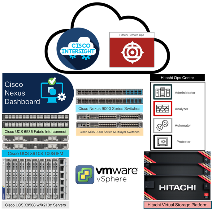
The Cisco and Hitachi components used in Adaptive Solutions designs have been validated within this reference architecture so you have a relevant example you can use to explicitly deploy in your environment or adjust as needed within the respective product compatibility lists of Cisco and Hitachi. The best practices are intended to be relevant across supported product families, but deployment steps may differ when using supported components other than those shown in this design. Each of the component families shown in Figure 1 (Cisco UCS, Cisco Nexus, Cisco MDS, and Hitachi VSP) offers platform and resource options to scale up or scale out the infrastructure while supporting the same features.
The Adaptive Solutions hardware is built with the following components:
• Cisco UCS X9508 Chassis with Cisco UCS X9108-100G Intelligent Fabric Modules and up to eight Cisco UCS X210c M7 Compute Nodes.
• Fifth-generation Cisco UCS 6536 Fabric Interconnects to support 10/25/40/100GbE and 16/32GbFC connectivity from various components.
• High-speed Cisco NX-OS-based Nexus 93600CD-GX switching design to supporting 100GE connectivity with up to 400GE uplink connections.
• Future-proof Cisco MDS 9124V switches to support up to 64G Fibre Channel connectivity.
• Hitachi Virtual Storage Platform 5000 series (VSP 5000 series) represents the industry’s highest performing and most scalable storage solution. Built on over 50 years of Hitachi engineering experience and innovation in the IT sector, VSP 5000 series offers superior performance, resiliency, and agility, featuring response times as low as 39 microseconds, scaling up to 69PB of storage, and all backed up with the industry’s first and most comprehensive 100 percent data availability guarantee.
The software components of the solution consist of:
• Cisco Intersight platform to deploy the Cisco UCS components and maintain and support the infrastructure.
• Cisco Intersight Assist Virtual Appliance to help connect Hitachi VSP, Cisco Nexus switches, Cisco MDS Switches, and VMware vCenter to Cisco Intersight, giving visibility and management capabilities to these elements.
• VMware vSphere 8.0 U1 to incorporate new features to the release, including the Cisco Intersight enabled Hardware Support Manager (HSM) of Cisco UCS firmware.
• Hitachi Ops Center Administrator to provide a unified management platform for Hitachi storage systems that manages and monitors their storage infrastructure from a single console, simplifying management tasks and improving operational efficiency.
• Hitachi Ops Center API Configuration Manager REST enables programmatic management of Hitachi storage systems. It is an independent and lightweight component that includes the CCI (Command Control Interface), which is used as part of the configuration manager REST API. It uses LAN or Fibre Channel network-based communication with the targeted storage system.
• Hitachi Remote Ops monitors, alerts, collects data and provides analytics to customers about Hitachi solutions continuously.
• VMware vCenter to set up and manage the virtual infrastructure as well as Cisco Intersight integration.
Cisco Unified Computing System X-Series
The Cisco UCS X-Series Modular System is designed to take the current generation of the Cisco UCS platform to the next level with its future-ready design and cloud-based management. Decoupling and moving the platform management to the cloud allows Cisco UCS to respond to customer feature and scalability requirements in a much faster and efficient manner. Cisco UCS X-Series state of the art hardware simplifies the data-center design by providing flexible server options. A single server type, supporting a broader range of workloads, results in fewer different data-center products to manage and maintain. The Cisco Intersight cloud-management platform manages Cisco UCS X-Series as well as integrating with third-party devices, including VMware vCenter and Hitachi storage, to provide visibility, optimization, and orchestration from a single platform, thereby driving agility and deployment consistency.
Figure 2. Cisco UCS X9508 Chassis
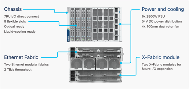
Cisco UCS X9508 Chassis
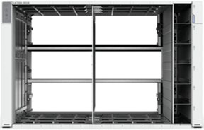
The Cisco UCS X-Series chassis is engineered to be adaptable and flexible. As shown in Figure 3, the Cisco UCS X9508 chassis has only a power-distribution midplane. This midplane-free design provides fewer obstructions for better airflow. For I/O connectivity, vertically oriented compute nodes intersect with horizontally oriented fabric modules, allowing the chassis to support future fabric innovations. Cisco UCS X9508 Chassis’ superior packaging enables larger compute nodes, thereby providing more space for actual compute components, such as memory, GPU, drives, and accelerators. Improved airflow through the chassis enables support for higher power components, and more space allows for future thermal solutions (such as liquid cooling) without limitations.
Figure 3. Cisco UCS X9508 Chassis – Midplane Free Design
The Cisco UCS X9508 7-Rack-Unit (7RU) chassis has eight flexible slots. These slots can house a combination of compute nodes and a pool of current and future I/O resources that includes GPU accelerators, disk storage, and nonvolatile memory. At the top rear of the chassis are two Intelligent Fabric Modules (IFMs) that connect the chassis to upstream Cisco UCS 6400 or 6500 Series Fabric Interconnects. At the bottom rear of the chassis are slots to house X-Fabric modules that can flexibly connect the compute nodes with I/O devices. Six 2800W Power Supply Units (PSUs) provide 54V power to the chassis with N, N+1, and N+N redundancy. A higher voltage allows efficient power delivery with less copper and reduced power loss. Efficient, 100mm, dual counter-rotating fans deliver industry-leading airflow and power efficiency, and optimized thermal algorithms enable different cooling modes to best support the customer’s environment.
Cisco UCS 9108-100G Intelligent Fabric Modules
In the end-to-end 100Gbps Ethernet design, for the Cisco UCS X9508 Chassis, the network connectivity is provided by a pair of Cisco UCS 9108-100G Intelligent Fabric Modules (IFMs). Like the fabric extenders used in the Cisco UCS 5108 Blade Server Chassis, these modules carry all network traffic to a pair of Cisco UCS 6536 Fabric Interconnects (FIs). IFMs also host the Chassis Management Controller (CMC) for chassis management. In contrast to systems with fixed networking components, Cisco UCS X9508’s midplane-free design enables easy upgrades to new networking technologies as they emerge making it straightforward to accommodate new network speeds or technologies in the future.
Figure 4. Cisco UCS 9108-100G Intelligent Fabric Module
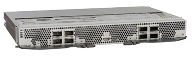
Each IFM supports eight 100Gb uplink ports for connecting the Cisco UCS X9508 Chassis to the FIs and 8 100Gb server ports for the eight compute nodes. IFM server ports can provide up to 200 Gbps of unified fabric connectivity per compute node across the two IFMs. The uplink ports connect the chassis to the Cisco UCS FIs, providing up to 1600Gbps connectivity across the two IFMs. The unified fabric carries management, VM, and Fibre Channel over Ethernet (FCoE) traffic to the FIs, where management traffic is routed to the Cisco Intersight cloud operations platform, FCoE traffic is forwarded to either native Fibre Channel interfaces through unified ports on the FI (to Cisco MDS switches) or to FCoE uplinks (to Cisco Nexus switches supporting SAN switching), and data Ethernet traffic is forwarded upstream to the data center network (using Cisco Nexus switches).
Cisco UCS X210c M7 Compute Node
The Cisco UCS X9508 Chassis is designed to host up to 8 Cisco UCS X210c M7 Compute Nodes. The hardware details of the Cisco UCS X210c M7 Compute Nodes are shown in Figure 5.
Figure 5. Cisco UCS X210c M7 Compute Node
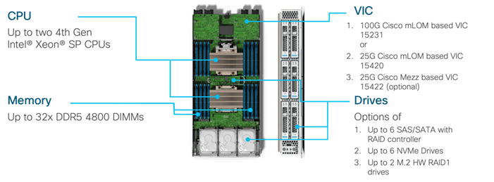
The Cisco UCS X210c M7 features:
• CPU: Up to 2x 4th Gen Intel Xeon Scalable Processors with up to 60 cores per processor and 2.6 MB Level 3 cache per core.
• Memory: Up to 32 x 256 GB DDR5-4800 DIMMs for a maximum of 8 TB of main memory.
• Disk storage: Up to 6 SAS or SATA drives can be configured with an internal RAID controller, or customers can configure up to 6 NVMe drives. 2 M.2 memory cards can be added to the Compute Node with optional RAID 1 mirroring.
• Virtual Interface Card (VIC): Up to 2 VICs including an mLOM Cisco UCS VIC 15231 (100Gbps) or an mLOM Cisco UCS VIC 15420 (50Gbps) and a mezzanine Cisco UCS VIC card 15422 can be installed in a Compute Node to pair with and extend the connectivity of the Cisco UCS VIC 15420 adapter.
• Security: The server supports an optional Trusted Platform Module (TPM). Additional security features include a secure boot FPGA and ACT2 anti-counterfeit provisions.
Cisco UCS VIC 15231
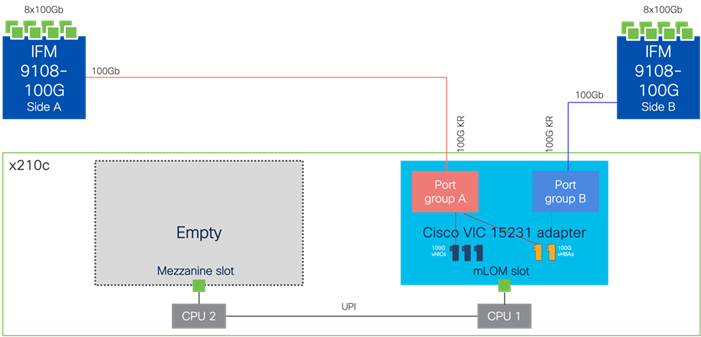
Cisco UCS VIC 15231 fits the mLOM slot in the Cisco UCS X210c Compute Node and enables up to 100 Gbps of unified fabric connectivity to each of the chassis IFMs for a total of 200 Gbps of connectivity per server. Cisco UCS VIC 15231 connectivity to the IFM and up to the fabric interconnects is delivered through 100Gbps. Cisco UCS VIC 15231 supports 512 virtual interfaces (both FCoE and Ethernet) capable of providing 100Gbps, along with the latest networking innovations including NVMeoF over FC or TCP, and VXLAN/NVGRE offload.
Figure 6. Cisco UCS VIC 15231 in Cisco UCS X210c M7
Cisco UCS 6536 Fabric Interconnects
The Cisco UCS Fabric Interconnects (FIs) provide a single point for connectivity and management for the entire Cisco UCS system. Typically deployed as an active/active pair, the system’s FIs integrate all components into a single, highly available management domain controlled by Cisco Intersight (currently, the Cisco UCS 6536 FI does not support Cisco UCS Manager). Cisco UCS FIs provide a single unified fabric for the system, with low-latency, lossless, cut-through switching that supports LAN, SAN, and management traffic using a single set of cables.
Figure 7. Cisco UCS 6536 Fabric Interconnect
The Cisco UCS 6536 FI utilized in the current design is a 36-port Fabric Interconnect. This single RU device includes up to 36 10/25/40/100 Gbps Ethernet ports, 16 8/16/32-Gbps Fibre Channel ports using four 128 Gbps to 4x32 Gbps breakouts on ports 33-36. All 36 ports support breakout cables or QSA interfaces.
Note: The Cisco UCS 6536 FI was initially released to only support Intersight Managed Mode (IMM). This has changed and Cisco UCS Manager (UCSM) mode is now supported on the Cisco UCS 6536 Fabric Interconnects to include Cisco UCS X-Series, Cisco UCS B-Series Blade Servers, Cisco UCS C-Series Rack Servers, Cisco UCS S-Series Storage Servers, as well as the associated storage resources and networks.
The Cisco Intersight platform is a Software-as-a-Service (SaaS) infrastructure lifecycle management platform that delivers simplified configuration, deployment, maintenance, and support. The Cisco Intersight platform is designed to be modular, so you can adopt services based on their individual requirements. The platform significantly simplifies IT operations by bridging applications with infrastructure, providing visibility and management from bare-metal servers and hypervisors to serverless applications, thereby reducing costs and mitigating risk. This unified SaaS platform uses a unified Open API design that natively integrates with third-party platforms and tools.
Figure 8. Cisco Intersight Overview
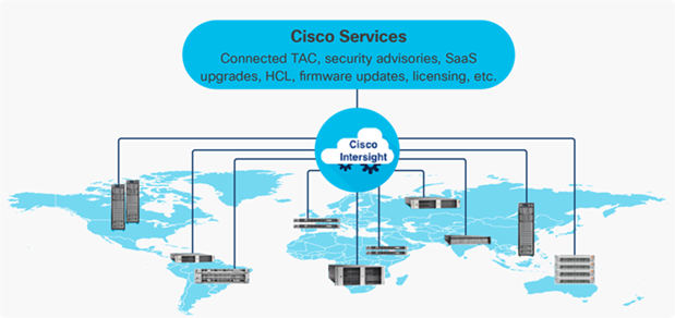
The main benefits of Cisco Intersight infrastructure services are as follows:
• Stay ahead of problems with global visibility and accelerate trouble resolution through proactive support capabilities.
• Provide role-based access control (RBAC) to resources within the data center through a single platform.
• Intersight Cloud Orchestrator (ICO) provides a task based “low code” workflow approach to executing storage operations.
• Combine the convenience of a SaaS platform with the capability to connect from anywhere and manage infrastructure through a browser or mobile app.
• Elimination of silos for managing datacenter ecosystem as all components, including Hitachi storage can be managed using Intersight.
• Upgrade to add workload optimization and Kubernetes services when needed.
The Cisco Nexus 9000 Series Switches offer both modular and fixed 1/10/25/40/100/400 Gigabit Ethernet switch configurations with scalability up to 115 Tbps of nonblocking performance with less than five-microsecond latency, wire speed VXLAN gateway, bridging, and routing support.
Figure 9. Cisco Nexus 93600CD-GX Switch
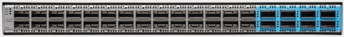
The Cisco Nexus 9000 series switch featured in this design is the Cisco Nexus 93600CD-GX configured in NX-OS standalone mode. NX-OS is a purpose-built data-center operating system designed for performance, resiliency, scalability, manageability, and programmability at its foundation. It provides a robust and comprehensive feature set that meets the demanding requirements of virtualization and automation.
The Cisco Nexus 93600CD-GX Switch is a 1RU switch that supports 12 Tbps of bandwidth and 4.0 bpps across 28 fixed 40/100G QSFP-28 ports and 8 fixed 10/25/40/50/100/200/400G QSFP-DD ports. Breakout supported on ports, 25-36: 2x200, 4x100, 2x100, 8x50, 4x50, 2x50, 4x25, 4x10, and 10G w/QSA. This switch was chosen for this solution because of its robust uplink capabilities in a 1RU format, and future-proofness of 400G capacity.
Port groups within the 93600CD-GX switches follow specific requirements when configuring breakout ports, which is explained in the hardware installation guide, here: https://www.cisco.com/c/en/us/td/docs/switches/datacenter/nexus9000/hw/n93600cd-gx-hig/guide/b_c93600cd-gx-nxos-mode-hardware-installation-guide/m_overview1.html
Cisco MDS 9124V 64G Multilayer Fabric Switch
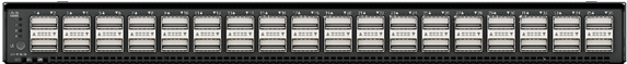
The next-generation Cisco MDS 9124V 64-Gbps 24-Port Fibre Channel Switch (Figure 10) supports 64, 32, and 16 Gbps Fibre Channel ports and provides high-speed Fibre Channel connectivity for all-flash arrays and high-performance hosts. This switch offers state-of-the-art analytics and telemetry capabilities built into its next-generation Application-Specific Integrated Circuit (ASIC) chipset. This switch allows seamless transition to Fibre Channel Non-Volatile Memory Express (NVMe/FC) workloads whenever available without any hardware upgrade in the SAN. It empowers small, midsize, and large enterprises that are rapidly deploying cloud-scale applications using extremely dense virtualized servers, providing the benefits of greater bandwidth, scale, and consolidation.
Figure 10. Cisco MDS 9124V 64G Multilayer Fabric Switch
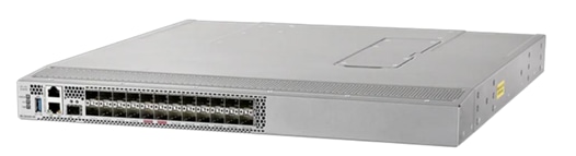
The Cisco MDS 9124V delivers advanced storage networking features and functions with ease of management and compatibility with the entire Cisco MDS 9000 family portfolio for reliable end-to-end connectivity. This switch also offers state-of-the-art SAN analytics and telemetry capabilities that have been built into this next-generation hardware platform. This new state-of-the-art technology couples the next-generation Cisco port ASIC with a fully dedicated network processing unit designed to complete analytics calculations in real time. The telemetry data extracted from the inspection of the frame headers are calculated on board (within the switch) and, using an industry-leading open format, can be streamed to any analytics-visualization platform. This switch also includes a dedicated 10/100/1000BASE-T telemetry port to maximize data delivery to any telemetry receiver including the Cisco Nexus Dashboard Fabric Controller. The Cisco MDS 9148V 48-Port Fibre Channel Switch is also available when more ports are needed.
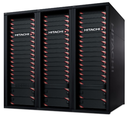
Hitachi Virtual Storage Platform
Hitachi Virtual Storage Platform is a highly scalable, true enterprise-class storage system that can virtualize external storage and provide virtual partitioning and quality of service for diverse workload consolidation. With the industry’s only 100 percent data availability guarantee, Virtual Storage Platform delivers the highest uptime and flexibility for your block-level storage needs.
Figure 11. Hitachi Virtual Storage Platform
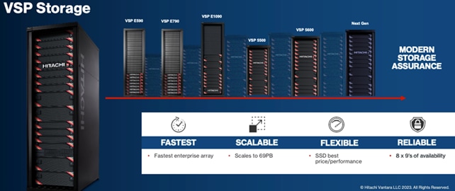
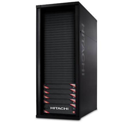
Hitachi Virtual Storage Platform 5000 Series
The VSP 5200 and VSP 5600 models provide enhanced capacity efficiency with improved data reduction performance along with SCM tiering and full end-to-end NVMe. Hitachi Virtual Storage Platform 5000 series storage systems reliably deliver more data faster than ever for open-systems and mainframe applications. These enterprise-level storage systems are available in configurations with up to 69 PB of raw capacity and with scalability to manage up to 33 million IOPS with latency as low as 39 µs accelerates application response and increases application consolidation, making these models the most powerful and most responsive storage systems available. The Hitachi Remote Ops monitoring system and Hitachi Ops Center Analyzer software enable superior uptime. To ensure that operations are always up and running, VSP 5000 series models can optionally be backed by a 100 percent data availability guarantee.
Hardware-assisted data reduction technology offers up to a 40 percent performance improvement over existing VSP 5000 series models. Nondisruptive data-in-place (DIP) migration is provided when upgrading from VSP 5100 to VSP 5600 or from VSP 5500 to VSP 5600.
VSP 5000 series provides high performance, high availability, and reliability for enterprise-class data centers and features the industry’s most comprehensive suite of local and remote data protection capabilities, including true active-active metro-clustering. When combined with server virtualization, storage virtualization supports applications at cloud scale while reducing complexity.
VSP 5000 series is the first storage in the industry to offer a mixed NVMe, SCM solid-state disk (SSD), serial-attached SCSI (SAS) SSD, and HDD environment that can not only scale up in capacity but also scale out for performance. VSP 5000 series models include the industry leading VSP 5100 and VSP 5500 models and the newest VSP 5200 and VSP 5600 models.
Figure 12. Hitachi Virtual Storage Platform 5600
Hitachi VSP 5000 Key Features
• Agility and scalability
VSP 5100 and VSP 5200 all-flash arrays (AFAs) are scale-up enterprise storage platforms with one pair of controller nodes supporting open and mainframe workloads. VSP 5500 and VSP 5600 AFAs start with a single node pair and can scale out to three node pairs. All of these models are also available as hybrid arrays (VSP 5100H, VSP 5200H, VSP 5500H, VSP 5600H) that support the following drive types:
◦ NVMe SCM
◦ NVMe SSD
◦ SAS SSD
◦ SAS FMD (available only when upgrading to VSP 5600)
◦ SAS HDD
Note: The VSP 5100 and VSP 5200 models support either SAS or NVMe configurations, while VSP 5500 and VSP 5600 support mixed SAS and NVMe backend configurations.
• All-flash performance accelerated by NVMe technology
NVMe drives provide high throughput and low latency to achieve high response performance, enabling large volumes of data to be processed rapidly with response times as low as 39 microseconds. NVMe storage class memory (SCM) drives provide significantly quicker access to data, up to 10 times faster than flash drives, and are more durable than flash drives.
• Capacity efficiency
The advanced adaptive data reduction (ADR) technologies of the VSP 5000 series provide a guaranteed effective capacity of 4:1 to improve storage utilization and reduce the storage footprint. Compression and also deduplication, if desired, can be enabled for all internal and external storage media at the volume level for enhanced tunability.
• Reliability and resiliency
Leveraging hot-swappable components, nondisruptive maintenance and upgrades, and outstanding data protection, VSP 5000 series offers complete system redundancy and is backed by a 100 percent data availability guarantee. The active-active controller architecture of VSP 5000 series protects against local faults and performance issues, and hardware redundancy eliminates all active single points of failure, no matter how unlikely, to provide the highest level of reliability and data availability.
• Artificial-intelligence-based solutions
All VSP 5000 series models come with Hitachi Ops Center Analyzer, which analyzes telemetry to optimize application performance and prevent extended outages. Manual administrative tasks are streamlined and implemented with fewer errors, facilitating the addition of new applications and the expansion of existing applications. In addition, Hitachi Ops Center Analyzer works with Hitachi Ops Center Automator to maintain best practices and quality of service (QoS).
• Simple, easy-to-use management
VSP 5000 series can be set up quickly and managed with ease using Hitachi Ops Center Administrator. Ops Center Administrator reduces the complexity of steps needed to deploy, monitor, and reconfigure storage resources. Additionally, REST APIs allow integration with existing toolsets and automation templates to further consolidate management tasks.
Hitachi Ops Center Suite delivers enhanced AIOps capabilities using AI/ML to provide real-time monitoring and to increase performance and tuning of your storage environment. For more information about Hitachi Virtual Storage Platform 5000 Series, see: https://www.hitachivantara.com/en-us/products/storage-platforms/primary-block-storage/vsp-5000-series.html
Hitachi Virtual Storage Platform E1090
The Hitachi Virtual Storage Platform E series builds on over 50 years of proven Hitachi engineering experience, offering you a superior range of business continuity options that provide the best reliability in the industry. As a result, 85 percent of Fortune 100 financial services companies trust Hitachi storage systems with their mission-critical data.
The Hitachi Virtual Storage Platform E1090 (VSP E1090) storage system is a high-performance, large-capacity data storage system. The VSP E1090 all-flash arrays (AFAs) support NVMe and SAS solid-state drives (SSDs). The VSP E1090H hybrid models can be configured with both SSDs and hard disk drives (HDDs).
The NVMe flash architecture delivers consistent, low-microsecond latency, which reduces the transaction costs of latency-critical applications and delivers predictable performance to optimize storage resources.
The hybrid architecture allows for greater scalability and provides data-in-place migration support.
The storage systems offer superior performance, resiliency, and agility, featuring response times as low as 41μ, all backed up with the industry’s first and most comprehensive 100% data availability guarantee.
The Hitachi Virtual Storage Platform E series innovative active-active controller architecture protects your business against local faults while mitigating performance issues as well as providing all enterprise features of the VSP 5000 series in a lower cost form factor to satisfy midrange customer needs and business requirements.
Hitachi VSP E1090 Key Features
• High performance
◦ Multiple controller configuration distributes processing across controllers
◦ High-speed processing facilitated by up to 1,024 GiB of cache
◦ I/O processing speed increased by NVMe flash drives
◦ High-speed front-end data transfer up to 32 Gbps for FC and 10 Gbps for iSCSI
◦ I/O response times as low as low as 41 μ
◦ Integrated with Hitachi Ops Center to improve IT operational efficiencies
• High reliability
◦ Service continuity for all main components due to redundant configuration
◦ RAID 1, RAID 5, and RAID 6 support (RAID 6 including 14D+2P)
◦ Data security by transferring data to cache flash memory in case of a power outage
• Scalability and versatility
◦ Scalable capacity up to 25.9 PB, 287 PB (external), and 8.4M IOPS
◦ The hybrid architecture allows for greater scalability and provides data-in-place migration support
• Performance and Resiliency Enhancements
◦ Upgraded controllers with 14 percent more processing power than VSP E990 and 53 percent more processing power than VSP F900
◦ Significantly improved adaptive data reduction (ADR) performance through Compression Accelerator Modules
◦ An 80 percent reduction in drive rebuild time compared to earlier midsized enterprise platforms
◦ Smaller access size for ADR metadata reduces overhead
◦ Support for NVMe allows extremely low latency with up to 5 times higher cache miss IOPS per drive
• Reliability and serviceability
The Virtual Storage Platform (VSP) E1090 storage system is designed to deliver industry-leading performance and availability. The VSP E1090 features a single, flash-optimized Storage Virtualization Operating System (SVOS) image running on 64 processor cores, sharing a global cache of 1 TiB. The VSP E1090 offers higher performance with fewer hardware resources than competitors. The VSP E1090 was upgraded to an advanced Cascade Lake CPU, permitting read response times as low as 41 microseconds and data reduction throughput was improved up to 2X by the new Compression Accelerator Module. Improvements in reliability and serviceability allow the VSP E1090 to claim an industry-leading 99.9999% availability (on average, 0.3 seconds per year of downtime expected).
• Advanced AIOps and easy-to-use management
The Hitachi Virtual Storage Platform E series achieves greater efficiency and agility with Hitachi Ops Center’s advanced AIOps which provide real-time monitoring for VSP E series systems located on-premises or in a colocation facility. Hitachi’s advanced AIOps provides unique integration of IT analytics and automation that identifies issues and, through automation, quickly resolves issues before they impact your critical workloads. Ops Center uses the latest AI and machine learning (ML) capabilities to improve IT operations through an Ops Center simplifies day-to-day administrative, optimization and management orchestration for VSP E-Series, freeing you to focus on innovation and strategic initiatives.
Figure 13. Hitachi Virtual Storage Platform E1090
For more information about Hitachi Virtual Storage Platform E series, see: https://www.hitachivantara.com/en-us/products/storage-platforms/primary-block-storage/vsp-e-series.html
Hitachi Virtual Storage Platform Software Components and Features
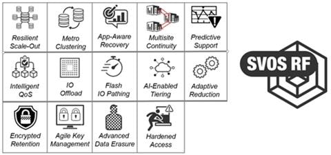
Hitachi Storage Virtualization Operating System RF
Hitachi Storage Virtualization Operating System (SVOS) RF (Resilient Flash) delivers best-in-class business continuity and data availability and simplifies storage management of all Hitachi VSP storage systems by sharing a common operating system. Flash performance is optimized with a patented flash-aware I/O stack to further accelerate data access. Adaptive inline data reduction increases storage efficiency while enabling a balance of data efficiency and application performance. Industry-leading storage virtualization allows Hitachi Storage Virtualization Operating System RF to use third-party all-flash and hybrid arrays as storage capacity, consolidating resources and extending the life of storage investments.
Hitachi Storage Virtualization Operating System RF works with the virtualization capabilities of the Hitachi VSP storage systems to provide the foundation for global storage virtualization. SVOS RF delivers software-defined storage by abstracting and managing heterogeneous storage to provide a unified virtual storage layer, resource pooling, and automation. Hitachi Storage Virtualization Operating System RF also offers self-optimization, automation, centralized management, and increased operational efficiency for improved performance and storage utilization. Optimized for flash storage, Hitachi Storage Virtualization Operating System RF provides adaptive inline data reduction to keep response times low as data levels grow, and selectable services enable data-reduction technologies to be activated based on workload benefit.
Hitachi Storage Virtualization Operating System RF integrates with Hitachi base and advanced software packages to deliver superior availability and operational efficiency. You gain active-active clustering, data-at-rest encryption, insights via machine learning, and policy-defined data protection with local and remote replication.
Figure 14. Hitachi Storage Virtualization Operating System RF Features
For more information about Hitachi Storage Virtualization Operating System RF, see: https://www.hitachivantara.com/en-us/products/storage-platforms/primary-block-storage/virtualization-operating-system.html
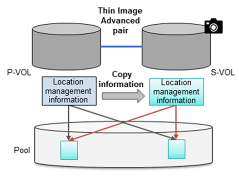
Hitachi Thin Image Provisioning Advanced
Hitachi Thin Image Advanced (HTI Advanced) enables you to perform cost-effective replication by storing only the differential data between the primary volumes (P-VOLs) and secondary volumes (S-VOLs). Thin Image Advanced stores snapshots in a Hitachi Virtual Storage Platform (VSP) family storage system. If a logical data failure occurs in the storage system due to erroneous data update or virus infection, you can restore it using the stored snapshot of the data. Pairs created by using Thin Image Advanced are called Thin Image Advanced pairs.
The high-speed, nondisruptive snapshot technology of Hitachi Thin Image Advanced snapshot software rapidly creates up to one million point-in-time copies of mission-critical information within any Hitachi storage system or virtualized storage pool, without impacting host service or performance levels. Because snapshots store only the changed data, the volume of storage capacity required for each snapshot copy volume is greatly reduced. As a result, Hitachi Thin Image Advanced can provide significant savings over full-volume cloning methods. These snapshot copies are fully read/write compatible with other hosts and can be used for system backups, application testing, and data mining applications while the business continues to run at full capacity.
• Thin Image Advanced snapshots rapidly create up to 1,024 instant point-in-time copies for data protection or application testing.
• Saves up to 90 percent or more disk space by storing only changed data blocks.
• Speeds backups from hours to a few minutes, virtually eliminating traditional backup windows.
• Near-instant restoration of critical data to increase business continuity.
• Application- and OS-independent but can be integrated with application backup triggers.
• Fast, simple, and reliable snapshot software.
Figure 15. Hitachi Thin Image Provisioning Advanced
For more information on Hitachi Thin Image Advanced, see: https://knowledge.hitachivantara.com/Documents/Management_Software/SVOS/9.8.7/Local_Replication/Thin_Image_Advanced/01_Overview_of_Thin_Image_Advanced
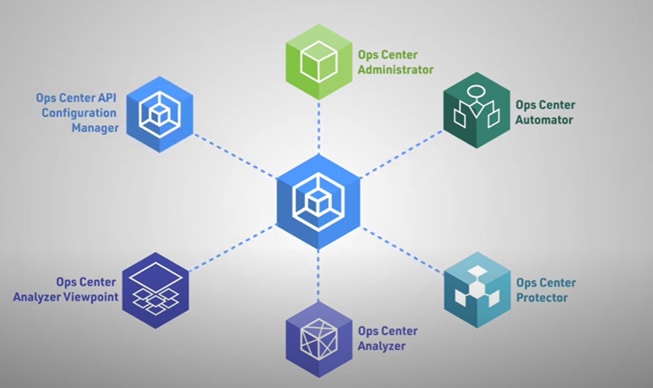
Hitachi Ops Center is an integrated suite of applications that enable you to optimize your data center operations through integrated configuration, analytics, automation, and copy data management. These features allow you to administer, automate, optimize, and protect your Hitachi storage infrastructure.
The following modules are included in Hitachi Ops Center:
• Ops Center Administrator
• Ops Center Analyzer
• Ops Center Automator
• Ops Center Protector
• Ops Center API Configuration Manager
• Ops Center Analyzer Viewpoint
Figure 16. Hitachi Ops Center Products
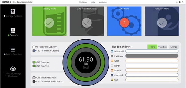
Hitachi Ops Center Administrator
Hitachi Ops Center Administrator is an infrastructure management solution that unifies storage provisioning, data protection, and storage management across the entire Hitachi Virtual Storage Platform family.
Figure 17. Hitachi Ops Center Administrator UI Console
The Hitachi Ops Center Administrator key benefits are:
• Reduction in administration time and effort to efficiently deploy and manage new storage resources via an easy to use interface.
• Utilization of common configurations to centrally manage multiple Hitachi Virtual Storage Platform systems.
• Standard based APIs which enable fast storage provisioning operations and integration with external tools.
• Utilization of common administrative workflows to manage highly available storage volumes.
• Integration with Hitachi Ops Center management to incorporate analytics, automation, and data protection.
For more information on Hitachi Ops Center Administrator, see: https://www.hitachivantara.com/en-us/products/storage-software/ai-operations-management/ops-center/administrator.html
Ops Center Analyzer
Ops Center Analyzer provides a comprehensive application service-level and storage performance management solution that enables you to quickly identify and isolate performance problems, determine the root cause, and provide solutions. It enables proactive monitoring from the application level through server, network, and storage resources for end-to-end visibility of your monitored environment. It also increases performance and storage availability by identifying problems before they can affect applications.
Figure 18. Hitachi Ops Center Analyzer UI Console
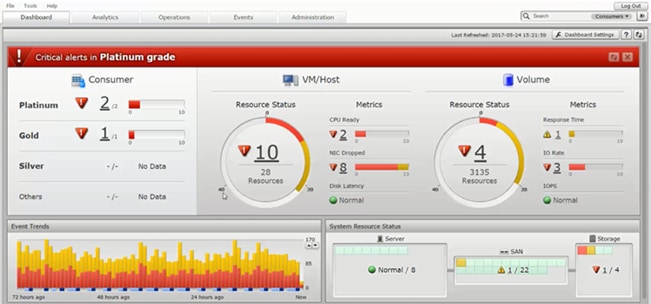
The Ops Center Analyzer collects and correlates data from these sources:
• Storage systems
• Fibre Channel switches
• Hypervisors
• Hosts
For more information about Hitachi Ops Center Analyzer, see: https://www.hitachivantara.com/en-us/products/storage-software/ai-operations-management/ops-center/analyzer.html
Ops Center Analyzer Viewpoint
Ops Center Analyzer viewpoint displays the operational status of data centers around the world in a single window allowing comprehensive insight to global operations.
Figure 19. Hitachi Ops Center Analyzer Viewpoint
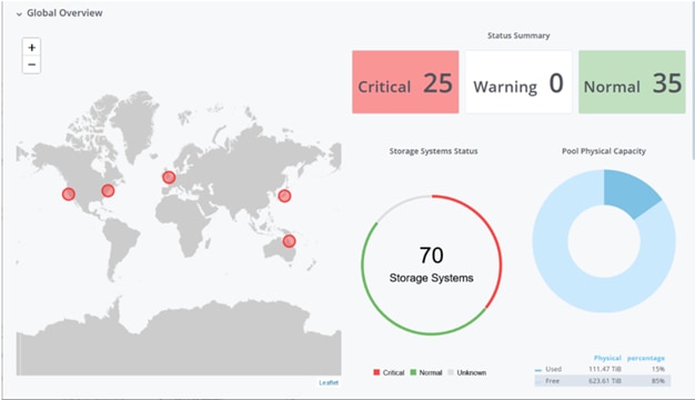
With Hitachi Ops Center Analyzer viewpoint, the following information can be utilized:
• Check the overall status of multiple data centers: By accessing Analyzer viewpoint from a web browser, you can collectively display and view information about supported resources in the data centers. Even for a large-scale system consisting of multiple data centers, you can check the comprehensive status of all data centers.
• Easily analyze problems related to resources: By using the UI, you can display information about resources in a specific data center in a drill-down view and easily identify where a problem occurred. Additionally, because you can launch the Ops Center Analyzer UI from the Analyzer viewpoint UI, you can quickly perform the tasks needed to resolve the problem.
For more Information about Ops Center, see: https://www.hitachivantara.com/en-us/products/storage-software/ai-operations-management/ops-center.html
Hitachi Ops Center Protector
With Hitachi Ops Center Protector you can easily configure in-system or remote-replication for the Hitachi VSP. Protector as a enterprise data copy management platform that provides business-defined data protection, which simplifies the creation and management of complex, business-defined policies to meet service-level objectives for availability, recoverability, and retention.
Figure 20. Hitachi Ops Center Protector UI Console
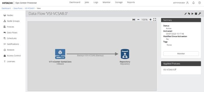
For more information about Hitachi Ops Center Protector, see: https://www.hitachivantara.com/en-us/products/storage-software/data-protection-cyber-resiliency/ops-center-protector.html
Hitachi Ops Center Automator
Hitachi Ops Center Automator is a software solution that provides automation to simplify end-to-end data management tasks such as storage provisioning for storage and data center administrators. The building blocks of the product are prepackaged automation templates known as service templates that can be customized and configured for other people in the organization to utilize as a self-service model therefore reducing the load on traditional administrative staff.
Figure 21. Hitachi Ops Center Automator UI Console
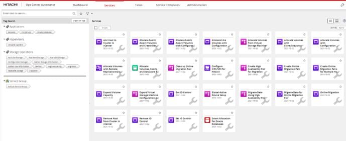
For more information on Hitachi Ops Center Automator, see: https://www.hitachivantara.com/en-us/products/storage-software/ai-operations-management/ops-center/automator.html
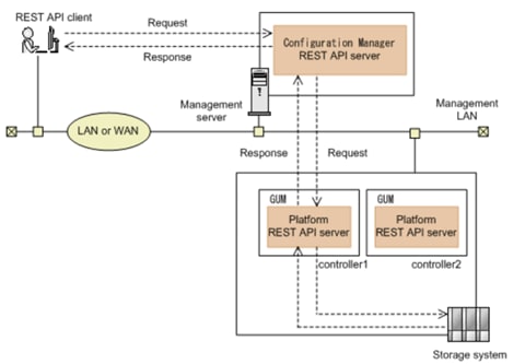
Hitachi Ops Center API Configuration Manager
Hitachi Ops Center API Configuration Manager REST is an independent and lightweight binary that enables programmatic management of Hitachi VSP storage systems using restful APIs. This component can be deployed stand-alone or as a part of Hitachi Ops Center.
The REST API supports the following storage systems:
• VSP 5000 series
• VSP E Series
• VSP F Series
• VSP G Series
Figure 22. Hitachi Ops Center API Configuration Manager
VMware vSphere is the enterprise workload platform that brings the benefits of cloud to on-premises workloads. VMware vSphere aggregates the infrastructure of an entire data center to create a single powerhouse with resources that can be allocated quickly and dynamically to any application in need.
VMware vSphere 8.0 Update 1 is validated in this release and officially launches vSphere Configuration Profiles, which allow you to manage ESXi cluster configurations by specifying a desired host configuration at the cluster level, automate the scanning of ESXi hosts for compliance to the specified Desired Configuration and remediate any host that is not compliant.
VMware vSphere Configuration Profiles are featured along with the Intersight enabled Hardware Support Manager, this will require that you use vSphere Lifecycle Manager images to manage your cluster lifecycle, a vSphere 8.0 Update 1 environment, and Enterprise Plus or vSphere+ license.
For additional features enabled by VMware vSphere 8.0 U1, refer to the release notes: https://docs.vmware.com/en/VMware-vSphere/8.0/rn/vsphere-vcenter-server-801-release-notes/index.html
This chapter contains the following:
• Physical End-to-End Connectivity
• Cisco UCS X-Series – Cisco Intersight Managed Mode
The Adaptive Solutions architecture delivers a validated reference architecture that is well suited for platforms handling electronic healthcare record (EHR) workloads like Epic with a cloud-managed infrastructure solution on the latest Cisco UCS hardware featuring the Cisco UCS 6536 Fabric Interconnect and the Cisco UCS X210c M7 Compute nodes. The Virtual Server Infrastructure architecture is built to deliver the VMware vSphere 8.0 U1 hypervisor with the Hitachi Virtual Storage Platform (VSP) providing the storage infrastructure serving stateless compute through SAN boot, as well as high performance block storage for the application. The Cisco Intersight cloud-management platform is utilized to configure and manage the infrastructure, with visibility at all layers of the architecture.
This release of the Adaptive Solutions architecture uses a high-speed Fibre Channel (FC)—based storage access design, with 100G Ethernet available for the compute layer for supporting the application. In this design, the Hitachi VSP 5600 and the Cisco UCS X-Series are connected through Cisco MDS 9124V Fibre Channel Switches providing boot from SAN over the FC network, with both FC and optional FC-NVMe validated for VMFS datastores. For the Epic benchmark testing that is discussed later in this document, FC based raw device mappings (RDM) were associated with the workload VMs.
The physical connectivity details of the topology are shown in Figure 23.
Figure 23. Adaptive Solutions VSI for vSphere 8.0 U1 Physical Topology
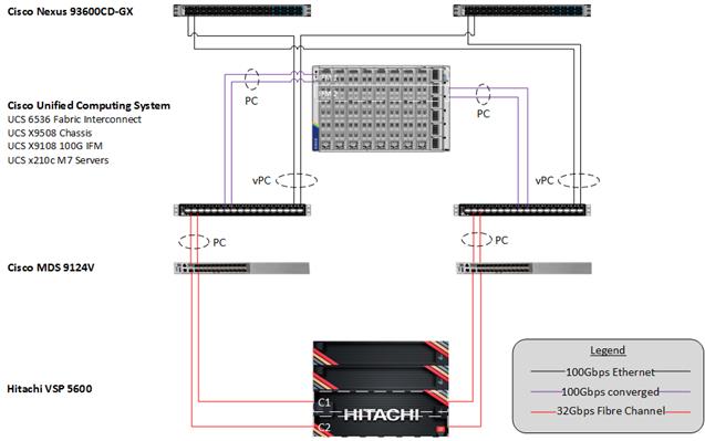
To validate the configuration, the components are set up as follows:
• Cisco UCS 6536 Fabric Interconnects provide the chassis and network connectivity.
• The Cisco UCS X9508 Chassis connects to fabric interconnects using Cisco UCS 9108-100G intelligent fabric modules (IFMs), where two 100 Gigabit Ethernet ports are used on each IFM to connect to the appropriate FI. If additional bandwidth is required, up to eight 100G ports can be utilized to the chassis.
• Cisco UCS X210c M7 Compute Nodes contain the fifth-generation Cisco 15231 virtual interface cards (VICs).
• Cisco UCS 6536 Fabric Interconnects are connected to the Cisco MDS 9124V switches using multiple 32-Gbps Fibre Channel connections (utilizing breakouts) configured as a single port channel for SAN connectivity.
• Cisco Nexus 93600CD-GX Switches in Cisco NX-OS mode provide the switching fabric.
• Cisco UCS 6536 Fabric Interconnect 100-Gigabit Ethernet uplink ports connect to Cisco Nexus 93600CD-GX Switches in a Virtual Port Channel (vPC) configuration.
• The Hitachi VSP 5600 is connected to the Cisco MDS 9124V using multiple 32Gbps Fibre Channel connections.
• VMware 8.0 U1 ESXi software is installed on Cisco UCSX-210c M7 Compute Nodes to validate the infrastructure.
In the Adaptive Solutions deployment, each Cisco UCS server equipped with a Cisco Virtual Interface Card (VIC) is configured for multiple virtual Network Interfaces (vNICs) and virtual Host Based Adapters(vHBAs), which appear as standards-compliant PCIe endpoints to the OS. The end-to-end logical connectivity delivers multi-pathing for the VLAN/VSAN connectivity between the server profile for an ESXi host and the storage configuration on the Hitachi VSP 5600 is described below.
Figure 24 illustrates the end-to-end connectivity design.
Figure 24. Logical End-to-End Connectivity
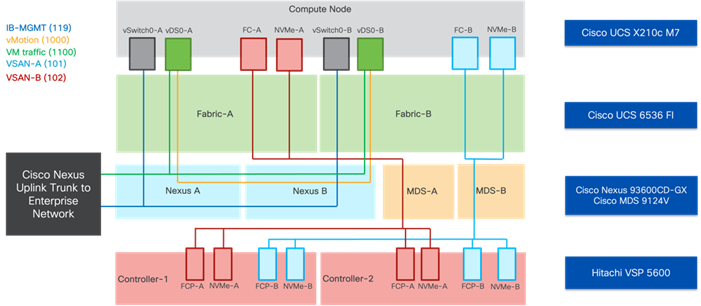
Each ESXi server profile supports:
• Managing the ESXi hosts using a common management segment.
• Diskless SAN boot using FC with persistent operating system installation for true stateless computing.
• The vNICs are:
◦ Two redundant vNICs (vSwitch0-A and vSwitch0-B) carry the management VLAN which is pinned to fabric A to keep ESXi management traffic primarily within fabric A. The MTU value for these vNICs is set as a Jumbo MTU (9000), but management interfaces with MTU 1500 can be placed on these vNICs.
◦ Two redundant vNICs (vDS0-A and vDS0-B) are used by vDS0 and carry VMware vMotion traffic and customer application data traffic. Like the management traffic, the vMotion traffic is pinned to fabric B to keep it contained within fabric B. The MTU for the vNICs is set to Jumbo MTU (9000), but interfaces that require MTU 1500 can be placed on these vNICs.
• Four vHBAs are (FC-NVMe vHBAs listed were not active in the Epic benchmark testing):
◦ Two vHBAs (one for FC and one for FC-NVMe) defined on Fabric A to provide access to SAN-A path.
◦ Two vHBAs (one for FC and one for FC-NVMe) defined on Fabric B to provide access to SAN-B path.
• Each ESXi host (compute node) mounts VMFS datastores and vVols from the Hitachi VSP 5600 for deploying virtual machines.
VLAN Configuration
Table 1 lists VLANs configured for setting up the environment along with their usage.
| VLAN ID |
Name |
Usage |
| 2 |
Native-VLAN |
Use VLAN 2 as native VLAN instead of default VLAN (1) |
| 19 |
OOB-MGMT-VLAN |
Out-of-band management VLAN to connect management ports for various devices |
| 119 |
IB-MGMT-VLAN |
In-band management VLAN utilized for all in-band management connectivity - for example, ESXi hosts, VM management, and so on. |
| 1000 |
vMotion |
VMware vMotion traffic |
| 1100 |
VM-Traffic |
VM data traffic VLAN |
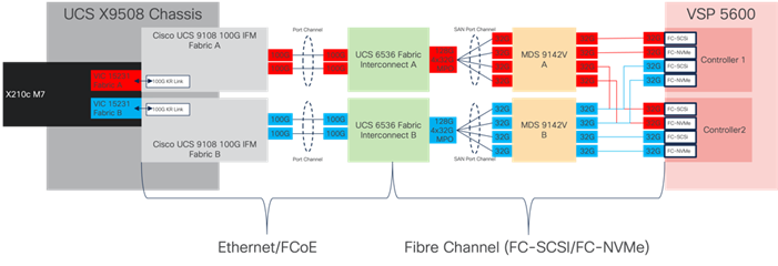
Physical End-to-End Connectivity
The physical end-to-end connectivity specific to the storage traffic is shown in Figure 25. The Fabric Interconnects create a demarcation of FCoE handling from the compute side as the VICs talk to the IFM and connect to the FIs. The server to IFM connection that the VICs participate in is a direct physical connection of KR links between the server and the IFM, differing from the previous generation of Cisco UCS 5108 Chassis where a physical KR lane structure mediated the traffic between the servers and the respective Cisco UCS IOMs.
Leaving the FIs, the traffic is converted to direct Fibre Channel packets carried within dedicated SAN port channels to the MDS. After being received by the MDS, the zoning within each MDS isolates the intended initiator to target connectivity between FC-SCSI and FC-NVMe as it proceeds to the VSP.
The specific connections as the storage traffic flows from a Cisco UCS X210c M7 server in a UCS environment to a Hitachi VSP 5600 storage system is as follows:
• Each Cisco UCS X210c M7 server is equipped with a Cisco UCS VIC 15231 adapter that connects to each fabric at a link speed of 100Gbps.
• The link from the Cisco UCS VIC 15231 is physically connected into the Cisco UCS 9108 100G IFM as they both reside in the Cisco UCS X9508 chassis.
• Connecting from each IFM to the Fabric Interconnect with pairs of 100Gb uplinks (can be increased to up to 8 100GB connections per IFM) that are automatically configured as port channels during chassis association, which carry the FC frames as FCoE along with the Ethernet traffic coming from the chassis.
• Continuing from the Cisco UCS 6536 Fabric Interconnects, a breakout MPO transceiver that presents multiple 32G FC ports configured as a port channel into the Cisco MDS 9124V, carrying FC-SCSI and FC-NVMe traffic, for increased aggregate bandwidth and link loss resiliency.
• Ending at the Hitachi VSP 5600 Fibre Channel controller ports with dedicated F_Ports on the Cisco MDS 9124V for each N_Port WWPN of the VSP controller, with each channel board (CHB).
Figure 25. Adaptive Solutions End-to-End Physical Multi-Pathing for Fibre Channel
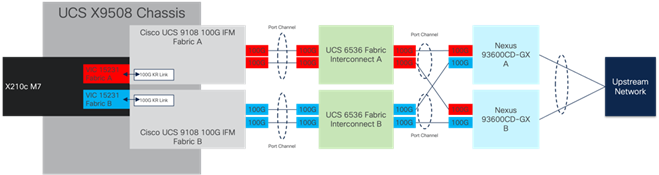
The dedicated Ethernet traffic utilizes the same links coming from the IFM into the FIs as shown in Figure 26, but will communicate beyond the FIs within a pair of port channels that are received across the upstream Nexus as two separate Virtual Port Channels (vPC) that each Nexus will participate in.
As with the FC storage traffic, the Ethernet data traffic follows similar paths as follows:
• Each Cisco UCS X210c M7 server is equipped with a VIC 15231 adapter that connects to each fabric at a link speed of 100Gbps.
• The link from the VIC 15231 is physically connected into the Cisco UCS Cisco UCS 9108 100G IFM as they both reside in the X9508 chassis.
• Connecting from each IFM to a dedicated Fabric Interconnect with pairs of 100Gb uplinks (can be increased to up to 8 100GB connections per IFM) that are automatically configured as port channels during chassis association.
• Connecting out of the Fabric Interconnects, the port channels are configured with two 100Gb uplinks to the Nexus that can be expanded as needed.
Figure 26. Adaptive Solutions End-to-End Physical Multi-Pathing for Ethernet
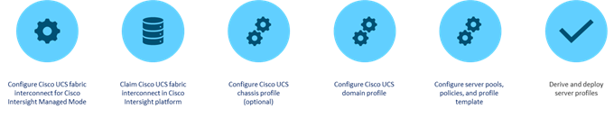
Cisco UCS X-Series - Cisco Intersight Managed Mode
Cisco Intersight Managed Mode standardizes policy and operation management for Cisco UCS X-Series and the remaining UCS hardware used in this CVD. The Cisco UCS compute nodes are configured using server profiles defined in Cisco Intersight. These server profiles derive all the server characteristics from various policies and templates. At a high level, configuring Cisco UCS using Intersight Managed Mode consists of the steps shown in Figure 27.
Figure 27. Configuration Steps for Cisco Intersight Managed Mode
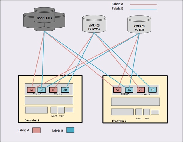
Each VSP storage system is comprised of multiple controllers and Fibre Channel adapters that control connectivity to the Fibre Channel fabrics via the MDS FC switches. Channel boards (CHBs) are used within the VSP 5600 models and have two controllers contained within the storage system. The multiple CHBs within each storage system allow for designing multiple layers of redundancy within the storage architecture, increasing availability, and maintaining performance during a failure event.
The VSP 5600 CHBs each contain up to four individual Fibre Channel ports, allowing for redundant connections to each fabric in the Cisco UCS infrastructure. The VSP CHBs each contain up to four individual Fibre Channel ports, allowing for redundant connections to each fabric in the Cisco UCS infrastructure. In this deployment 4 ports are configured for FC-SCSI protocol, one from controller 1 (CL1-A) and one from controller 2 (CL2-A) going into MDS fabric A, as well as one from controller 1 (CL3-A) and one from controller 2 (CL4-A) going into MDS fabric B for a total of 4 connections. These connections provide the data path to boot LUNs and VMFS datastores that utilize FC-SCSI protocol. Additionally, 4 ports are configured for FC-NVMe, one from controller 1 (CL1-B) and one from controller 2 (CL2-B) going into MDS fabric A, and one from controller 1 (CL3-B) and one from controller 2 (CL4-B) going into MDS fabric B to provide an additional data path for VMFS datastores that utilize the FC-NVMe protocol.
With the Cisco UCS ability to provide alternate data paths each, Fibre Channel fabric provides total of 16 paths, with four paths to each host which hold boot LUN as well as for VMFS datastores per host, comprised of two paths on each fabric. If you plan to deploy VMware ESXi hosts, each host’s WWN should be in its own host group. This approach provides granular control over LUN presentation to ESXi hosts. This is the best practice for SAN boot environments such as Cisco UCS, because ESXi hosts do not have access to other ESXi hosts’ boot LUNs.
Figure 28. Logical View of LUNs to VSP 5600 Port Association
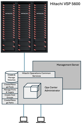
Hitachi Ops Center Administrator
Within this design, Hitachi Ops Center Administrator was used to configure the VSP 5600 to provide boot LUNs and VMFS datastores to the VSI infrastructure hosted on the Cisco UCS.
You can perform the following operations from the Hitachi Ops Center Administrator (Figure 29):
Figure 29. Hitachi Ops Center Administrator
The following are the operations performed through Hitachi Ops Center Administrator:
• Initialization of parity groups
Parity groups are the basic units of storage capacity. Creating parity groups converts the raw disk capacity in your storage system into usable capacity. Using Administrator the parity group can be initialized to a basic LDEV which can be now used for pool creation of HDP or HDT.
Note: For VSP 5600 series, Parity groups cannot be created via Ops Center Administrator, but can be initialized in Ops Center Administrator.
If you choose to use the basic method to create parity groups, Ops Center Administrator automatically reviews the available spare disks and allocates more spare disks if needed. If you choose to create parity groups using the advanced method, you should review the number of spare disks in the parity groups inventory summary. To assign more or fewer spare disks, use disk management.
• Creating a boot and application pool
When parity groups have been initialized, pools can be created to provide thin provisioned volumes for host or application use, there are two different options to create a pool, that is, basic and advanced. When creating a pool, use the basic option to take advantage of tiers that are based on best practices. If you want more flexibility and do not need to take advantage of best practices, you can use the advanced option to select specific parity groups.
The pool types are as follows:
• HDP (Dynamic Provisioning), which allocates virtual volumes to a host and uses the physical capacity that is necessary according to the data write request.
• Tiered, which is used with Dynamic Provisioning and places data in a hardware tier according to the I/O load. For example, a data area that has a high I/O load is placed in a high-speed hardware tier, and a data area that has a low I/O load is placed in a low-speed hardware tier.
• Optional: HTI (Thin Image), which stores snapshot data in pools. A pool consists of multiple pool-VOLs. The pool-VOLs contain the snapshot data. A pool can contain up to 1,024 pool-VOLs.
Within this design, HDP pools were utilized to provide both boot LUNs and VMFS datastores to the VSI infrastructure.
• Managing port security and settings
Before Ops Center Administrator can create a host storage domain (HSD) on a port, you may need to change the port security and settings such as port attributes. For example, port security must be enabled for Fibre or iSCSI ports. By default, security is disabled on supported storage systems. If port security is disabled, Ops Center Administrator does not select the port for host storage domain (HSD) creation.
To provision volumes based on FC-SCSI and FC-NVMe ports in Ops Center Administrator, set the following:
◦ For Fibre with SCSI mode ports: Enable Security
◦ For Fibre with NVMe mode ports: Disable Security
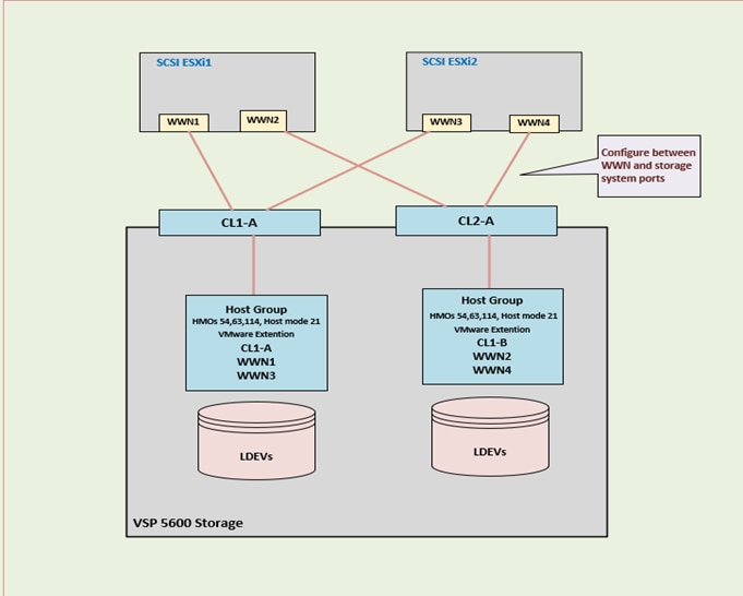
• Server and server groups inventory
With Hitachi Ops Center Administrator, you can utilize the concept of servers to onboard the Cisco UCS servers used to support VSI. Servers can be added by defining their HBA WWNs related to fabric A and fabric B for both FC-SCSI and FC-NVMe, as well as in the case of FC-NVMe host NQN identifier. This definition will create the traditional host group on the Hitachi VSP as well as namespace used for the FC-NVMe protocol. After servers have been onboarded, they can be placed in server groups for easy one click allocation of boot LUNs for VMFS datastores to the entire cluster.
While attaching volumes to Server or Server groups, the following settings for Host mode options (HMOs) and Host mode need to be selected with the protocol as FC-SCSI:
◦ Host mode: 63 ((VAAI) Support Option for vStorage APIs based on T10 standards) must be enabled
◦ Host mode: 21 VMware Extension since Host operating system is VMware server with LUSE volume support.
Figure 30. FC-SCSI Storage Logical Provisioning
This chapter contains the following:
Epic is in use across a broad range of practices, from community hospitals and independent practices to multi-specialty hospital groups and hospice care providers. The Adaptive Solutions reference architecture is a reliable choice for Epic deployments, delivering performance, which is both resilient and scalable to meet customer needs.
The performance of Epic’s operational database (ODB) is critical in Epic deployments. To benchmark the performance of running Epic workloads within the Adaptive Solutions architecture, Cisco and Hitachi have followed Epic best practices to run their IO simulator GenerateIO (GenIO) within the solution architecture described in this paper. Epic developed their GenIO simulator to simulate workload scenarios that are commonly seen in real-world Epic production environments to ensure that a storage solution meets the critical service level objectives. For a storage system to meet the necessary performance for supporting Epic workloads, it must meet critical service level objectives (SLO).
The benchmarking was conducted within the infrastructure resources detailed in the Adaptive Solutions Virtual Server Infrastructure CVD. Table 2 lists the physical and logical components required to execute the GenIO simulator.
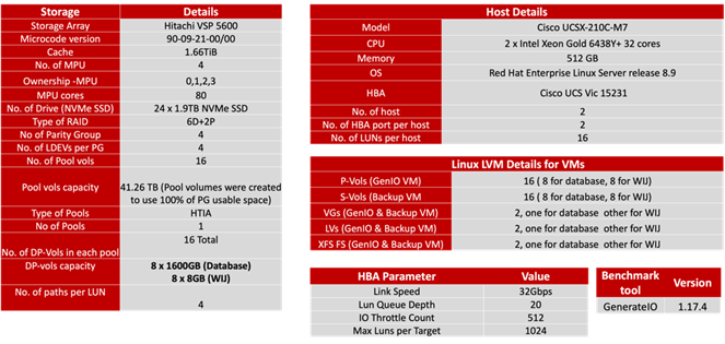
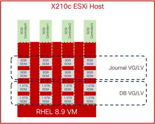
Within this infrastructure environment, two RHEL systems were provisioned and associated with a dedicated UCSX-210-M7 ESXi host. vSphere RDM LUNs were configured on each RHEL system for GenIO testing. Figure 31 shows the storage allocation layout for the RHEL 8.9 VMs used for GenIO and backup benchmarking:
Figure 31. GenIO VM Storage Layout
The GenIO simulator was used to benchmark the system characteristics of the Cisco and Hitachi Adaptive Solutions Virtual Server Infrastructure. The objective of the GenIO simulator testing was to determine an Epic benchmark reference point for a standard Cisco and Hitachi Adaptive Solutions Virtual Server Infrastructure solution. This GenIO reference point could be used for comparison against a customer’s Epic requirements.
The GenIO simulator was run on a single vSphere VM and simulated workload traffic on a Hitachi VSP 5600 configured with the Hitachi Thin Image Advanced (HTI Advanced) feature. HTI Advanced is a new snapshot mechanism that uses Redirect on Write (RoW) snapshot technology. It is used for logical backup, repurposing data, data warehouse and recovery against logical corruption or ransomware. HTI Advanced is implemented with Primary-Volumes (P-Vols) and Secondary-Volumes (S-Vols) in Paired State. When an array level Snapshot is executed, the Paired State Volumes are split. GenIO was used to performance test HTI Advanced with Paired Volumes to establish a steady state benchmark. Subsequently, GenIO was used to establish a benchmark during the execution of an array level Snapshot. The GenIO Steady State benchmark maintained a consistent IOPs rate of 133K to demonstrate the efficiency of HTI Advanced with P-Vols and S-Vols in Paired State.
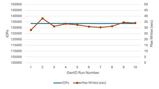
GenIO Benchmarking for HTI Advanced Paired Volumes
GenIO benchmarking was performed with HTI Advanced Primary-Volumes (P-Vols) and Secondary-Volumes (S-Vols) in Paired State with a consistent IOPs rate for the duration of the GenIO test execution. Figure 32 documents the consistent GenIO benchmark IOPs rate and the maximum number of writes completed per second with the Hitachi VSP 5600.
Figure 32. GenIO Benchmark w/Hitachi VSP 5600 in HTI Advanced Paired State
GenIO Benchmarking for HTI Advanced Snapshot
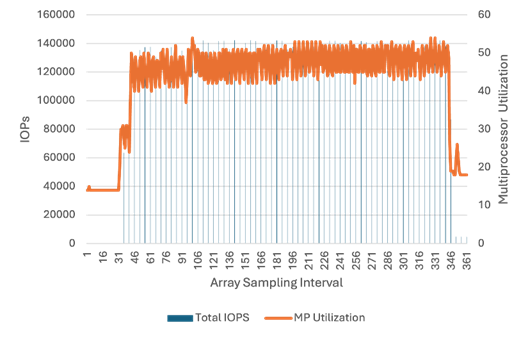
GenIO benchmarking was initiated with HTI Advanced P-Volumes and S-Volumes in Paired State. After GenIO had been running for one hour, Hitachi Storage Navigator was used to create a snapshot on the HTI Advanced Paired Volumes on the Hitachi VSP 5600 during GenIO Run Number 2. Snapshot creation on the Hitachi VSP 5600 did not incur a performance penalty on the Hitachi VSP 5600. The GenIO test execution continued with the HTI Advanced P-Vols and S-Vols in Split State. The GenIO IOPs rate continued to be supported at 133K IOPs. For the same GenIO test, the first graph below depicts the GenIO Benchmark IOPs and Max Writes per second, while the second graph depicts Hitachi VSP 5600 IOPs vs Multiprocessor utilization. The following data documents the GenIO performance with consistent IOPs vs Max Writes (sec) performance during an array level snapshot:
Figure 33. GenIO Benchmark IOPs vs Max Writes (sec) w/ Hitachi VSP 5600 Snapshot
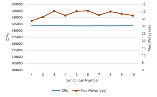
Figure 34. Hitachi VSP 5600 HTI Advanced Snapshot w/GenIO IOPs vs Multiprocessor Utilization
Additional information for Hitachi VSP 5600 with Epic GenIO testing results can be found at the following URL with a partner id:
Deployment Hardware and Software
This chapter contains the following:
• Hardware and Software Revisions
Hardware and Software Revisions
Table 3 lists the hardware and software used in this solution.
Table 3. Hardware and Software Revisions
| Component |
Software |
|
| Network |
Cisco Nexus 93600CD-GX |
10.2(5)M |
| Cisco MDS 9124V |
9.3(2) |
|
| Nexus Dashboard |
2.3(2d) |
|
| Nexus Dashboard Fabric Controller |
12.1.2e |
|
| Compute |
Cisco UCS Fabric Interconnect 6536 and UCS 9108-100G IFM |
4.3(2b) |
| Cisco UCS X210c with Cisco UCS VIC 15231 |
5.1(1.230052) |
|
| Cisco UCS Tools |
1.3.3-1OEM |
|
| Cisco VIC nenic Driver for ESXi |
2.0.11.0 |
|
| Cisco VIC nfnic Driver for ESXi |
5.0.0.41 |
|
| VMware ESXi |
Cisco Custom 8.0 U1a (with 8.0 U1c patch) |
|
| VMware vCenter Appliance |
8.0 U1c |
|
| Cisco Intersight Assist Virtual Appliance |
1.0.9-588 (automatically upgrades to current release) |
|
|
|
Epic GenerateIO |
1.17.4 |
| Storage |
Hitachi VSP 5600 |
SVOS 90-09-21-00/01 |
| Ops Center Administrator/CM Rest |
10.9.3 |
|
Ramesh Isaac, Technical Marketing Engineer, Cisco Systems, Inc.
Ramesh Isaac is a Technical Marketing Engineer in the Cisco UCS Data Center Solutions Group. Ramesh has worked in the data center and mixed-use lab settings for over 25 years. He started in information technology supporting UNIX environments and focused on designing and implementing multi-tenant virtualization solutions in Cisco labs before entering Technical Marketing where he has supported converged infrastructure and virtual services as part of solution offerings as Cisco. Ramesh has held certifications from Cisco, VMware, and Red Hat.
Gilberto Pena Jr., Virtualization Solutions Architect, Hitachi Vantara
Gilberto Pena Jr. Is a Virtualization Solution Architect in the Hitachi Vantara in the Engineering Converged UCP Group. Gilberto has over 25 years of experience with Enterprise financial customers focusing on LAN and WAN design and most recently converged and hyperconverged virtualization designs. Gilberto has held certifications from Cisco.
Acknowledgements
For their support and contribution to the design, review, and creation of this Cisco Validated Design, the authors would like to thank:
• Jeff Nichols, Leader, Technical Marketing, Cisco Systems, Inc.
• Arvin Jami, Solutions Architect, Hitachi Vantara
This appendix contains the following:
• Compute
• Network
• Storage
• Epic
Cisco Intersight: https://www.intersight.com
Cisco Intersight Managed Mode: https://www.cisco.com/c/en/us/td/docs/unified_computing/Intersight/b_Intersight_Managed_Mode_Configuration_Guide.html
Cisco Unified Computing System: https://www.cisco.com/site/us/en/products/computing/servers-unified-computing-systems/index.html
Cisco UCS 6536 Fabric Interconnects: https://www.cisco.com/c/en/us/products/collateral/servers-unified-computing/ucs6536-fabric-interconnect-ds.html
Cisco Nexus 9000 Series Switches: http://www.cisco.com/c/en/us/products/switches/nexus-9000-series-switches/index.html
Cisco MDS 9124V Switches: https://www.cisco.com/c/en/us/products/collateral/storage-networking/mds-9100-series-multilayer-fabric-switches/mds-9124v-fibre-channel-switch-ds.html
Cisco Nexus Dashboard Fabric Controller: https://www.cisco.com/c/en/us/products/collateral/cloud-systems-management/prime-data-center-network-manager/nb-06-ndfc-ds-cte-en.html
Hitachi Virtual Storage Platform E series: https://www.hitachivantara.com/en-us/products/storage-platforms/primary-block-storage/vsp-e-series.html
Hitachi Virtual Storage Platform 5000 series: https://www.hitachivantara.com/en-us/products/storage-platforms/primary-block-storage/vsp-5000-series.html
Hitachi SVOS: https://www.hitachivantara.com/en-us/products/storage-platforms/primary-block-storage/virtualization-operating-system.html
Hitachi Ops Center: https://www.hitachivantara.com/en-us/products/storage-software/ai-operations-management/ops-center.html
VMware vCenter Server: http://www.vmware.com/products/vcenter-server/overview.html
VMware vSphere: https://www.vmware.com/products/vsphere
Epic: https://www.epic.com
Cisco UCS Hardware Compatibility Matrix: https://ucshcltool.cloudapps.cisco.com/public/
VMware and Cisco Unified Computing System: http://www.vmware.com/resources/compatibility
Hitachi Product Compatibility Guide: https://compatibility.hitachivantara.com/
For comments and suggestions about this guide and related guides, join the discussion in the Cisco Community at https://cs.co/en-cvds.
CVD Program
ALL DESIGNS, SPECIFICATIONS, STATEMENTS, INFORMATION, AND RECOMMENDATIONS (COLLECTIVELY, "DESIGNS") IN THIS MANUAL ARE PRESENTED "AS IS," WITH ALL FAULTS. CISCO AND ITS SUPPLIERS DISCLAIM ALL WARRANTIES, INCLUDING, WITHOUT LIMITATION, THE WARRANTY OF MERCHANTABILITY, FITNESS FOR A PARTICULAR PURPOSE AND NONINFRINGEMENT OR ARISING FROM A COURSE OF DEALING, USAGE, OR TRADE PRACTICE. IN NO EVENT SHALL CISCO OR ITS SUPPLIERS BE LIABLE FOR ANY INDIRECT, SPECIAL, CONSEQUENTIAL, OR INCIDENTAL DAMAGES, INCLUDING, WITHOUT LIMITATION, LOST PROFITS OR LOSS OR DAMAGE TO DATA ARISING OUT OF THE USE OR INABILITY TO USE THE DESIGNS, EVEN IF CISCO OR ITS SUPPLIERS HAVE BEEN ADVISED OF THE POSSIBILITY OF SUCH DAMAGES.
THE DESIGNS ARE SUBJECT TO CHANGE WITHOUT NOTICE. USERS ARE SOLELY RESPONSIBLE FOR THEIR APPLICATION OF THE DESIGNS. THE DESIGNS DO NOT CONSTITUTE THE TECHNICAL OR OTHER PROFESSIONAL ADVICE OF CISCO, ITS SUPPLIERS OR PARTNERS. USERS SHOULD CONSULT THEIR OWN TECHNICAL ADVISORS BEFORE IMPLEMENTING THE DESIGNS. RESULTS MAY VARY DEPENDING ON FACTORS NOT TESTED BY CISCO.
CCDE, CCENT, Cisco Eos, Cisco Lumin, Cisco Nexus, Cisco StadiumVision, Cisco TelePresence, Cisco WebEx, the Cisco logo, DCE, and Welcome to the Human Network are trademarks; Changing the Way We Work, Live, Play, and Learn and Cisco Store are service marks; and Access Registrar, Aironet, AsyncOS, Bringing the Meeting To You, Catalyst, CCDA, CCDP, CCIE, CCIP, CCNA, CCNP, CCSP, CCVP, Cisco, the Cisco Certified Internetwork Expert logo, Cisco IOS, Cisco Press, Cisco Systems, Cisco Systems Capital, the Cisco Systems logo, Cisco Unified Computing System (Cisco UCS), Cisco UCS B-Series Blade Servers, Cisco UCS C-Series Rack Servers, Cisco UCS S-Series Storage Servers, Cisco UCS X-Series, Cisco UCS Manager, Cisco UCS Management Software, Cisco Unified Fabric, Cisco Application Centric Infrastructure, Cisco Nexus 9000 Series, Cisco Nexus 7000 Series. Cisco Prime Data Center Network Manager, Cisco NX-OS Software, Cisco MDS Series, Cisco Unity, Collaboration Without Limitation, EtherFast, EtherSwitch, Event Center, Fast Step, Follow Me Browsing, FormShare, GigaDrive, HomeLink, Internet Quotient, IOS, iPhone, iQuick Study, LightStream, Linksys, MediaTone, MeetingPlace, MeetingPlace Chime Sound, MGX, Networkers, Networking Academy, Network Registrar, PCNow, PIX, PowerPanels, ProConnect, ScriptShare, SenderBase, SMARTnet, Spectrum Expert, StackWise, The Fastest Way to Increase Your Internet Quotient, TransPath, WebEx, and the WebEx logo are registered trade-marks of Cisco Systems, Inc. and/or its affiliates in the United States and certain other countries. (LDW_P1)
All other trademarks mentioned in this document or website are the property of their respective owners. The use of the word partner does not imply a partnership relationship between Cisco and any other company. (0809R)