Cisco Data Intelligence Platform with Cloudera Data Platform
Available Languages
Bias-Free Language
The documentation set for this product strives to use bias-free language. For the purposes of this documentation set, bias-free is defined as language that does not imply discrimination based on age, disability, gender, racial identity, ethnic identity, sexual orientation, socioeconomic status, and intersectionality. Exceptions may be present in the documentation due to language that is hardcoded in the user interfaces of the product software, language used based on RFP documentation, or language that is used by a referenced third-party product. Learn more about how Cisco is using Inclusive Language.
- US/Canada 800-553-2447
- Worldwide Support Phone Numbers
- All Tools
 Feedback
 Feedback
In partnership with:
![]()

About the Cisco Validated Design Program
The Cisco Validated Design (CVD) program consists of systems and solutions designed, tested, and documented to facilitate faster, more reliable, and more predictable customer deployments. For more information, go to: http://www.cisco.com/go/designzone.
In today's rapidly evolving digital landscape, businesses are increasingly reliant on data-driven insights and innovative technologies to drive productivity, automated processes, enhanced decision making and stay competitive. Leveraging enterprise data for generative AI (genAI) enables customized content generation, personalized recommendations, automated document creation, and improved natural language understanding. These models can also analyze data for insights, summarize content, assist in data labeling, and aid in risk management and compliance.
Integrating generative AI into enterprise data management architecture for model training and inference demands a robust infrastructure capable of handling diverse data sources, scalable storage, and processing. This includes dedicated resources like GPUs and high-performance computing for efficient model training and inferencing, alongside strong data governance practices ensuring compliance and privacy. Flexibility is essential to accommodate varying data sources and training techniques, while experimentation and version control facilitate reproducibility and collaboration.
Machine learning is integral to leveraging enterprise data for creating business-specific models creation and inferences. This process involves collecting and preparing data, engineering features, selecting, and training models, evaluating their performance, deploying them for inferencing, and monitoring their ongoing performance.
Establishing feedback mechanisms and data pipelines enables continuous improvement by collecting and integrating user feedback into model updates. Automated testing and validation processes help maintain model accuracy and reliability before deployment, ensuring the effectiveness of generative AI and LLMs in delivering business value.
Adoption of artificial intelligence (AI) and machine learning (ML) related tools and use cases for business-specific use cases comes with several challenges. Firstly, ensuring the quality and integrity of data is crucial, as ML models heavily rely on clean and relevant data. Data privacy and security concerns also need to be addressed, especially when dealing with sensitive information. Additionally, acquiring and retaining skilled personnel proficient in AI and ML is a challenge, as these fields require specialized knowledge.
Integrating AI and ML into existing systems can be complex and may require significant changes to infrastructure. Moreover, validating and explaining the decisions made by AI and ML models is important for gaining trust and regulatory compliance. With the rapid advancements in AI and ML technologies requires continuous learning and adaptation. Overcoming these challenges is essential to successfully harnessing the potential of AI and ML in enterprise data management.
Successful adoption of generative AI tools in an enterprise requires defining clear objectives, preparing high-quality data, selecting the right model architecture, training, and fine-tuning the model, setting up deployment infrastructure, integrating with existing systems, providing user training and support, continuous monitoring, and improving the model, ensuring ethical and regulatory compliance, and measuring success and ROI.
This Cisco Validated Design explains the implementation of Cisco Data Intelligence platform with Cloudera Data Platform Private Cloud Base (CDP Private Cloud) 7.1.9 and Cloudera Private Cloud Data Services 1.5.3. Cisco Data Intelligence platform leveraging Cisco UCS and Cisco Nexus switch-based infrastructure with the Cloudera Data Platform (CDP) Private Cloud provides a scalable, high-performance, and secure environment for deploying generative AI and MLOps solutions. Cisco UCS rack and modular blade servers combined with Cisco Nexus switches' high-speed, low-latency connectivity, ensure optimal performance for training AI models. CDP's data management and governance capabilities, integrated with Cisco infrastructure, ensure the security and compliance of enterprise data. Furthermore, CDP supports MLOps practices with tools for model deployment, monitoring, and automation, while Cisco's reliability features and centralized management enhance infrastructure resilience and efficiency. This integration fosters collaboration and streamlines the end-to-end AI lifecycle, making it suitable for deploying and managing AI workloads in enterprise environments.
This chapter contains the following:
● Audience
Today, most enterprises are re-evaluating their data strategy in recognition of the transformative potential of AI technologies. The landscape is changing rapidly as more AI tools are available to address various needs for the organizations. There is a deeper integration of AI/ML in various systems, workflows, and applications as enterprises gain more experience through adoption of AI-Native or AI-first approach.
AI-First
Enterprises can leverage AI to enhance existing operations, address specific business challenges, and drive innovation without requiring massive architectural changes or disruptions. Due to evolutionary nature of AI adoption, use-case specificity and challenges associated with data quality, availability, and governance, resource constraints, and regulatory compliance, AI-First can be strategic approach to incorporate AI tools and technologies into existing systems and processes to leverage current infrastructure investment. This strategy enables firms to progressively develop AI capabilities, experiment with new technologies, and scale up as they acquire expertise.
AI-Native
Enterprise’s data strategy to be AI-Native involves seamless integration of artificial intelligence into all aspects of data processes. From data gathering and management to meet the requirement suited for AI processing. Continuous learning and development are vital for ensuring that AI models grow in response to new data and feedback. AI is deeply integrated into existing or new emerging business processes, with a focus on ethics, transparency, scalability, and flexibility, ensuring fair and accountable AI usage while supporting the organization's growth and innovation.
Cisco Data Intelligence Platform (CDIP) with Cloudera Data Platform Private cloud offers a powerful solution for enterprises looking to leverage advanced AI capabilities from either AI-First or AI-Native approach defined above. A unified platform for managing and analyzing data, making it well-suited for deploying and scaling generative AI workloads.
● Data Management: A unified platform for storing and managing data from various sources, ensuring data quality and governance.
● Scalable Infrastructure: A scalable infrastructure for training and deploying generative AI models, allowing for efficient resource utilization.
● Model Development: CML's Jupyter notebook environment enables data scientists to experiment with different generative models and frameworks, leveraging CDIP's data for training.
● Model Deployment: Deploy trained generative models as REST APIs or batch inference jobs on Cloudera Private Cloud, enabling integration with business applications.
● Monitoring and Management: Monitor model performance and resource utilization in real-time using Cisco Intersight and Cloudera Management portal for monitoring capabilities, ensuring reliability and scalability.
● Security and Compliance: Ensure data security and compliance with regulatory requirements
The architecture supports existing and new generative AI use cases and applications such as:
Natural Language Processing (NLP)
● Text Generation: Use generative models like GPT (Generative Pre-trained Transformer) to generate human-like text for tasks such as content creation, chatbots, and conversational interfaces.
● Language Translation: Employ models like Transformer-based architectures for language translation tasks, allowing for more accurate and context-aware translations.
Computer Vision
● Image Synthesis: Utilize generative adversarial networks (GANs) to synthesize images, enabling applications like style transfer, image inpainting, and image super-resolution.
● Anomaly Detection: Train anomaly detection models to identify unusual patterns or objects in images, useful for quality control and surveillance.
Recommendation Systems
● Content Generation: Develop generative models to create personalized content recommendations, such as movie recommendations, product recommendations, or personalized news articles.
● Personalized marketing: businesses can develop generative models to create personalized product recommendations, tailored marketing content, and chatbots for enhanced customer engagement.
Risk Analysis
● Data Augmentation: Use generative models to augment time series data, creating synthetic data for training forecasting models, which can enhance model generalization and robustness. Simulate different scenarios for risk analysis or generate alternative strategies for decision support.
Financial Services
● Fraud Prevention: Employ generative models to generate synthetic data for training fraud detection models, improving the prevention of fraudulent activities in financial transactions.
● Anomaly Detection: Train generative models to recognize anomalies based on historic data and patterns, allowing for early detection of unusual patterns in systems like network traffic, sensor data, or financial transactions.
● Portfolio Optimization: Use generative models to simulate different market scenarios and generate synthetic financial data for portfolio optimization strategies.
Healthcare
● Medical Image Generation: generate medical images for tasks such as MRI, CT, or X-ray imaging, aiding in data augmentation and anomaly detection.
● Drug Discovery: Utilize generative models to generate novel molecular structures for drug discovery, accelerating the process of identifying potential drug candidates.
The intended audience for this document includes, but is not limited to, sales engineers, field consultants, professional services, IT managers, IT engineers, partners, and customers who are interested in learning about and deploying the Cloudera Data Platform Private Cloud (CDP Private Cloud) on the Cisco Data Intelligence Platform on Cisco UCS M7 Rack-Mount servers and Cisco UCS X-Series for digital transformation through cloud-native modern data analytics and AI/ML.
This document describes the architecture, installation, configuration, and validated use cases for the Cisco Data Intelligence Platform using Cloudera Data Platform Private Cloud (Cloudera Data Platform Private Cloud Base and Cloudera Data Platform Private Cloud Data Services) on Cisco UCS M7 Rack-Mount servers. A reference architecture is provided to configure the Cloudera Data Platform on Cisco UCS C240 M7 with Nvidia H100, L40S and A100 GPU.
This solution extends the Cisco’s AI-native portfolio with Cisco Data Intelligence Platform (CDIP) comprised of Cisco UCS Infrastructure and Cloudera Data Platform Private Cloud, a state-of-the-art platform, providing a data cloud for demanding workloads that is easy to deploy, scale and manage. Furthermore, as the enterprise’s requirements and needs changes overtime, the platform can grow to thousands of servers, at exabytes of storage and tens of thousands of cores to process this data.
The following will be implemented in this validated design:
● Cisco UCS C240 M7 Rack Server with option to add GPUs
● Cisco UCS X210c M7 compute node with Cisco UCS X440p PCIe node
● Solution deployment with end-end 100G connectivity
● Automated OS deployment through Cisco Intersight
● Cloudera Data Platform Private Cloud Data Services with Embedded Container Service
● Cloudera Data Platform Private Cloud based on-prem Generative AI deployment
● NVIDIA H100 and L40S GPU for generative AI model training and inferencing
In this release, you will be exploring Cloudera Data Platform Private Cloud with GPU to deploy LLM, LLAMA and various use cases for model training and inferencing through Cloudera Machine Learning.
This chapter contains the following:
● Cisco Data Intelligence Platform
This CVD details the process of installing CDP Private Cloud on Cisco UCS Server and configuration details of fully tested and validated generative AI workloads in the cluster.
Cisco Data Intelligence Platform
Cisco Data Intelligence Platform (CDIP) is a cloud-scale architecture, primarily for a private cloud data lake which brings together big data, AI/compute farm, and storage tiers to work together as a single entity while also being able to scale independently to address the IT needs in the modern data center.
Deploying Large Language Models (LLMs) like GPT or Llama on the Cisco Data Intelligence Platform offers a powerful solution for enterprises looking to leverage advanced AI capabilities. The CDIP provides a unified platform for managing and analyzing data with centralized management and fully supported software stack (in partnership with industry leaders in the space) making it well-suited for deploying and scaling LLMs.
Scalable Infrastructure: A scalable infrastructure, leveraging Cisco UCS servers and Cisco Nexus switches, to handle the computational demands of training and inference for LLMs. This ensures that organizations can deploy LLMs of varying sizes and complexities without worrying about infrastructure constraints.
Unified Data Management: A unified platform for managing and processing data, including structured and unstructured data, which is crucial for training and fine-tuning LLMs. The platform supports data ingestion, preprocessing, and storage, enabling seamless integration of diverse data sources into LLM workflows.
Integration with Machine Learning Frameworks: Integration with popular machine learning frameworks such as TensorFlow and PyTorch, allowing data scientists to develop and train LLMs using their preferred tools and workflows. This integration streamlines the model development process and enables efficient experimentation and iteration.
Model Deployment and Monitoring: Support for model deployment and monitoring, allowing organizations to deploy trained LLMs into production environments and monitor their performance in real-time. This ensures that deployed models are functioning optimally and enables quick response to any issues or changes in data patterns.
Security and Governance: A comprehensive set of features and capabilities to address security and governance challenges in the deployment of generative AI and LLMs.
Collaboration and Integration: Facilitate collaboration among data scientists, developers, and IT operations teams involved in LLM deployment. It provides a centralized platform for sharing code, models, and insights, fostering collaboration and knowledge sharing across the organization.
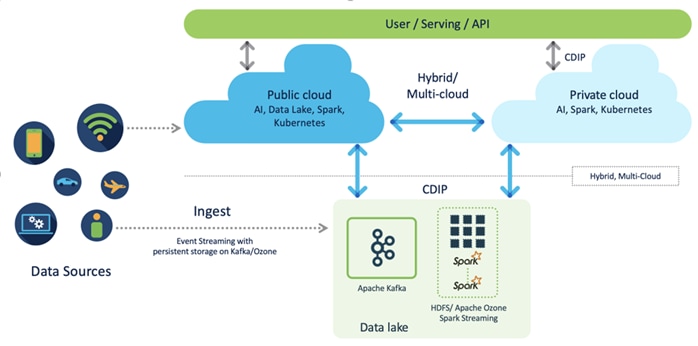
CDIP offers private cloud which enables it to become a hybrid cloud for the data lakes and apps which provides unified user experiences with common identity, single API framework that stretches from private cloud to public cloud, auto-scales when app demand grows. Further, implement tighter control over sensitive data with data governance and compliance, and integrate common data serving layer for data analytics, business intelligence, AI inferencing, and so on.
CDIP with CDP Private Cloud is built to meet the needs of enterprises for their AI-native, hybrid cloud with unmatched choices such as any data, any analytics, and engineering anywhere. This solution includes:
● Flexibility to run workload anywhere for quick and easy insights.
● Security that is consistent across all clouds provided by Cloudera’s SDX. Write centrally controlled compliance and governance policies once and apply everywhere, enabling safe, secure, and compliant end-user access to data and analytics.
● Performance and scale to optimize TCO across your choices. It brings unparalleled scale and performance to your mission-critical applications while securing future readiness for evolving data models.
● Single pane of glass visibility for your infrastructure and workloads. Register multi-cloud, including public and private in a single management console and launch virtual analytic workspaces or virtual warehouses within each environment as needed.
● Secure data and workload migration to protect your enterprise data and deliver it where is needed. Securely manage data and meta-data migration across all environments.
● Unified and multi-function Analytics for cloud-native workloads whether real-time or batch. Integrates data management and analytics experiences across the entire data lifecycle for data anywhere.
● Hybrid and multi-cloud data warehouse service for all modern, self-service, and advanced analytics use cases, at scale.
● Track and Audit everything across entire ecosystem of CDIP deployments.
CDIP with CDP Private Cloud Hybrid Uses Cases
With the increasing hybrid cloud adoption due to increasing data volume and variety, CDIP addresses use cases that caters to the needs of today’s demand of hybrid data platforms, such as the following:
● Hybrid Workload – Offload workload on-premises to cloud or vice-versa as per the requirements or auto-scale during peak hours due to real-time urgency.
● Hybrid Pipelines – Implement and optimize data pipelines for easier management. Automate and orchestrate your data pipelines as per demand or where it is needed the most. Implement secure data exchange between choice of your cloud and on-premises data hub at scale
● Hybrid Data Integration – Integrate data sources among clouds. Simplify application development or ML model training that needs on-premises data sources or cloud-native data stores
● Hybrid DevOps – Accelerate development with dev sandboxes in the cloud, however, production runs on-premises
● Hybrid Data Applications – Build applications that runs anywhere for cost, performance, and data residency
Cisco Data Intelligence Platform with Cloudera Data Platform
Cisco developed numerous industry leading Cisco Validated Designs (reference architectures) in the area of Big Data, compute farm with Kubernetes (CVD with RedHat OpenShift Container Platform) and Object store.
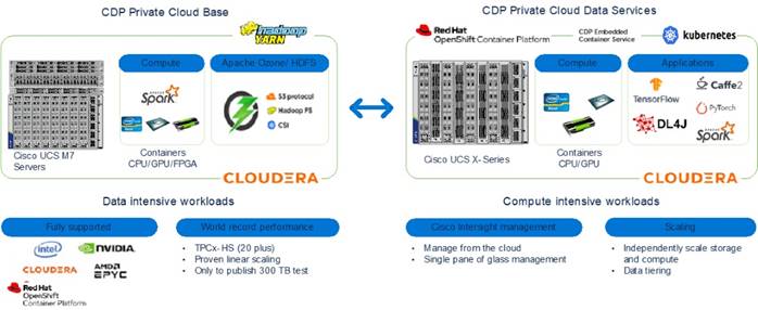
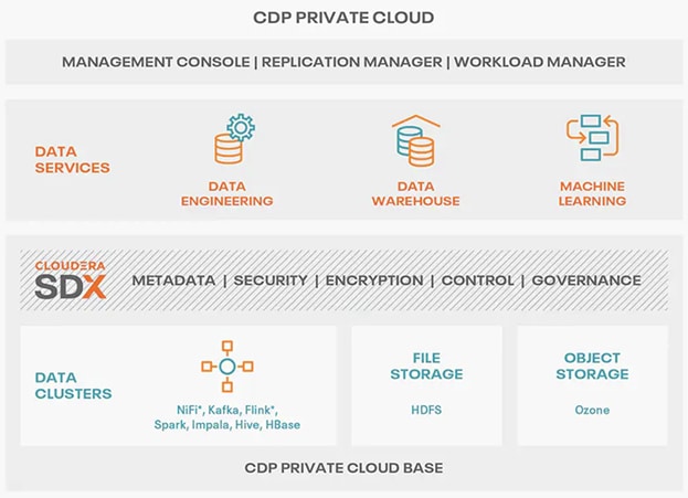
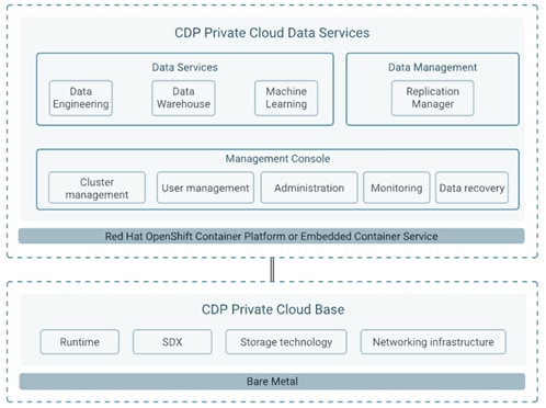
A CDIP architecture as a private cloud can be fully enabled by the Cloudera Data Platform with the following components:
● Data Lakehouse enabled through CDP Private Cloud Base
● Containerized AI/Compute can be enabled through CDP Private Cloud Data Services
● Exabyte storage enabled through Apache Ozone
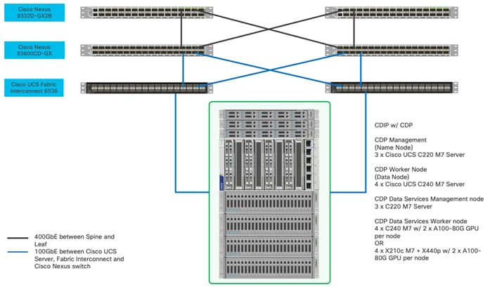
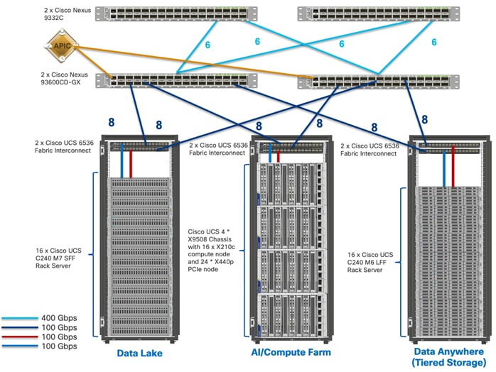
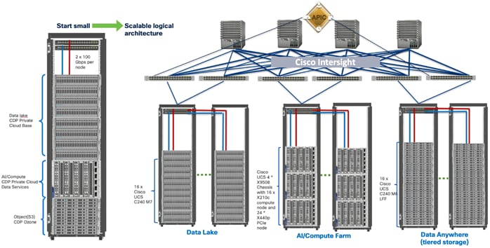
This architecture can start from a single rack (Figure 2) and scale to thousands of nodes with a single pane of glass management with Cisco Application Centric Infrastructure (ACI) (Figure 3).
Cisco Data Intelligence Platform reference architectures are carefully designed, optimized, and tested with the leading big data and analytics software distributions to achieve a balance of performance and capacity to address specific application requirements. You can deploy these configurations as is or use them as templates for building custom configurations. You can scale your solution as your workloads demand, including expansion to thousands of servers using Cisco Nexus 9000 Series Switches. The configurations vary in disk capacity, bandwidth, price, and performance characteristics.
Data Lake (CDP Private Cloud Base) Reference Architecture
Table 1 lists the CDIP with CDP Private Cloud data lake and dense storage with Apache Ozone reference architecture.
Table 1. Cisco Data Intelligence Platform with CDP Private Cloud Base Configuration on Cisco UCS M7
|
|
High Performance |
Performance |
Capacity |
| Server |
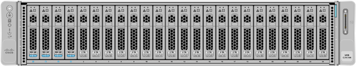
16 x Cisco UCS C240 M7SN Rack Servers with small-form-factor (SFF) drives |
16 x Cisco UCS C240 M7SX Rack Servers with small-form-factor (SFF) drives |
16 x Cisco UCS C240 M6 Rack Servers with large-form-factor (LFF) drives |
| CPU |
2 x 4th Gen Intel Xeon Scalable Processors 6448H processors (2 x 32 cores, at 2.4 GHz) |
2 x 4th Gen Intel Xeon Scalable Processors 6448H processors (2 x 32 cores, at 2.4 GHz) |
2 x 3rd Gen Intel Xeon Scalable Processors 6338 processors (2 x 32 cores, at 2.0 GHz) |
| Memory |
16 x 32 GB RDIMM @4800 MHz (512 GB) |
16 x 32 GB RDIMM @4800 MHz (512 GB) |
16 x 32 GB RDIMM DRx4 3200 MHz (512 GB) |
| Boot |
M.2 with 2 x 960-GB SSDs |
M.2 with 2 x 960-GB SSDs |
M.2 with 2 x 960-GB SSDs |
| Storage |
14 x 3.8TB 2.5in U2 NVMe and 2 x 3.2TB NVMe |
24 x 2.4TB 12G SAS 10K RPM SFF HDD (4K) (or 24 x 3.8TB Enterprise Value 12G SATA SSDs) and 2 x 3.2TB NVMe |
16 x 16TB 12G SAS 7.2K RPM LFF HDD(4K) and 2 x 3.2TB NVMe |
| Virtual Interface Card (VIC) |
Cisco VIC 15238 (2x 40/100/200G) |
Cisco VIC 15238 (2x 40/100/200G) |
Cisco VIC 15238 (2x 40/100/200G) |
| Storage Controller |
NA |
Cisco Tri-Mode 24G SAS RAID Controller w/4GB Cache |
Cisco 12-Gbps SAS modular RAID controller with 4-GB FBWC |
| Network Connectivity |
Cisco UCS 6536 Fabric Interconnect |
Cisco UCS 6536 Fabric Interconnect |
Cisco UCS 6536 Fabric Interconnect |
| GPU (optional) |
NVIDIA Tesla GPU |
NVIDIA Tesla GPU |
|
Note: The reference architecture highlighted here is the sizing guide for Apache Ozone based deployment. When sizing data lake for HDFS, Cloudera doesn’t support exceeding 100 TB per data node and drives larger than 8 TB. For more information, visit HDFS and Ozone section in CDP Private Cloud Base hardware requirement: https://docs.cloudera.com/cdp-private-cloud-base/7.1.9/installation/topics/cdpdc-runtime.html
Compute Farm (CDP Private Cloud DS) Reference Architecture
Table 2 lists the reference architecture for CDIP with CDP Private Cloud Data Services configuration for master and worker nodes.
Table 2. Cisco Data Intelligence Platform with CDP Private Cloud Data Services configuration
|
|
High Core Option |
High Core Option |
| Servers |
Cisco UCS C240 M7SN (SFF 2U Rack Server) |
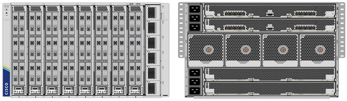
Cisco UCS X-Series 9508 chassis with X210C M7 Compute Node (Up to 8 Per chassis) |
| CPU |
2 x 4th Gen Intel Xeon Scalable Processors 6448H processors (2 x 32 cores, at 2.4 GHz) |
2 x 4th Gen Intel Xeon Scalable Processors 6448H processors (2 x 32 cores, at 2.4 GHz) |
| Memory |
16 x 64GB RDIMM DRx4 3200 MHz (1TB) |
16 x 64GB RDIMM DRx4 3200 MHz (1TB) |
| Boot |
M.2 with 2 x 960GB SSD |
M.2 with 2 x 960GB SSD |
| Storage |
Up to 24 x NVMe |
Up to 6 x NVMe |
| VIC |
Cisco VIC 15238 (2x 40/100/200G) |
Cisco UCS VIC 15231 2x100G mLOM for X Compute Node |
| Storage controller |
NA |
Cisco UCS X210c Compute Node compute pass through controller for up to 6 NVMe drives |
| Network connectivity |
Cisco UCS 6536 Fabric Interconnect |
Cisco UCS 6536 Fabric Interconnect |
| GPU (optional) |
NVIDIA Tesla GPU |
Cisco UCS X440p with NVIDIA Tesla GPU |
Note: For list of GPU supported on Cisco UCS X210c M7 Compute Node, go to: https://www.cisco.com/c/dam/en/us/products/collateral/servers-unified-computing/ucs-x-series-modular-system/x210cm7-specsheet.pdf#G3.1670569
Note: NVMe storage capacity and quantity needs to be updated based on the dataset requirement. For more information, go to CDP Private Cloud DS hardware requirements: https://docs.cloudera.com/cdp-private-cloud-data-services/1.5.3/installation-ecs/topics/cdppvc-installation-ecs-hardware-requirements.html
Note: For the list of support NVIDIA GPU on C240 M7 and X210c M7, refer to the spec sheet with supported GPU.
Note: Cisco UCS C240 M7 SFF Rack Server spec sheet: https://www.cisco.com/c/dam/en/us/products/collateral/servers-unified-computing/ucs-c-series-rack-servers/c240m7-sff-specsheet.pdf
Note: Cisco UCS X210c M7 compute node spec sheet: https://www.cisco.com/c/dam/en/us/products/collateral/servers-unified-computing/ucs-x-series-modular-system/x210cm7-specsheet.pdf
As illustrated in Figure 3, this CVD was designed with the following:
● Cisco Intersight managed Cisco UCS Server
● Cisco UCS Server network connectivity with Cisco Nexus Switch
● Cloudera Data Private Cloud Base 7.1.9
● Cloudera Data Private Data Services 1.5.3
● Cisco UCS Server with NVIDIA GPU for GenAI workload/application(s).
Note: This deployment guide was tested with NVIDIA H100, L40S and A100 installed in Cisco UCS C240 M7 and Cisco UCS X210c M7 with Cisco UCS X440p PCIE node. For more details on supported NVIDIA GPU and installation steps, refer to the spec sheet and server installation and service guide for Cisco UCS Server.
Scale the Architecture
As illustrated in Figure 4, the reference architecture highlighted in the deployment guide can be further extended to multiple racks catering to specific data storage, processing and generative AI model training and inferencing for the large-scale enterprise deployment with healthy data-movement.
This chapter contains the following:
● Cisco Data Intelligence Platform
● Cisco Unified Computing System
● Cloudera Data Platform (CDP)
● Cloudera Machine Learning (CML)
Cisco Data Intelligence Platform
This section describes the components used to build Cisco Data Intelligence Platform, a highly scalable architecture designed to meet a variety of scale-out application demands with seamless data integration and management integration capabilities.
Cisco Data Intelligence Platform powered by Cloudera Data Platform delivers:
● Latest generation of CPUs from Intel (3rd generation Intel Scalable family, with Ice Lake CPUs).
● Cloud scale and fully modular architecture where big data, AI/compute farm, and massive storage tiers work together as a single entity and each CDIP component can also scale independently to address the IT issues in the modern data center.
● World record Hadoop performance both for MapReduce and Spark frameworks published at TPCx-HS benchmark.
● AI compute farm offers different types of AI frameworks and compute types (GPU, CPU, FPGA) for model training, inferencing and analytics.
● A massive storage tier enables to gradually archive data and quick retrieval when needed on a storage dense sub-system with a lower $/TB providing a better TCO.
● Seamlessly scale the architecture to thousands of nodes.
● Single pane of glass management with Cisco Intersight.
● ISV Partner ecosystem – Top notch ISV partner ecosystem, offering best of the breed end-to-end validated architectures.
● Pre-validated and fully supported platform.
● Disaggregate Architecture supports separation of storage and compute for a data lake.
● Container Cloud, Kubernetes, compute farm backed by the industry leading container orchestration engine and offers the very first container cloud plugged with data lake and object store.
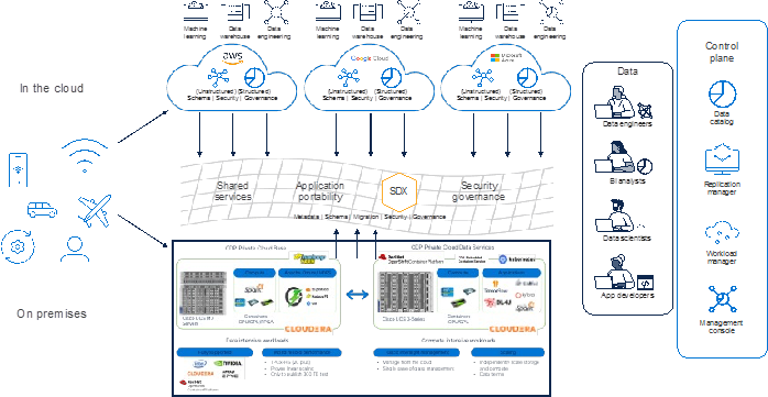
CDIP with CDP Hybrid Cloud Architecture
Cisco Data Intelligent Platform (CDIP) with Cloudera Data Platform (CDP) integrates different domains, such as specific layers of compute infrastructure between on-premises environments and public clouds. Integrations can include moving a Kubernetes-based application to establish secure connectivity, user access, or policies per workloads between environments. These hybrid cloud architecture frameworks and operating models are better defined with the more encompassing term hybrid IT, which also includes multi-cloud scenarios enabling distributed nature of the infrastructure that can assure elasticity, scalability, performance, and efficiency as well as bring apps closer to their intended users with ability to cloud burst.
Red Hat OpenShift or Embedded Container Service (ECS) being the preferred container cloud platform for CDP private cloud and so is for CDIP, is the market leading Kubernetes powered container platform. This combination is the first enterprise data-cloud hybrid architecture that decouples compute and storage for greater agility, ease-of-use, and more efficient use of private and multi-cloud infrastructure resources. With Cloudera’s Shared Data Experience (SDX), security and governance policies can be easily and consistently enforced across data and analytics in private as well as multi-cloud deployments. This hybridity will open myriad opportunities for seamless portability of workloads and applications for multi-function integration with other frameworks such as streaming data, batch workloads, analytics, data pipelining/engineering, and machine learning.
Cloud Native Architecture for Data Lake and AI
Cisco Data Intelligence Platform with CDP private cloud accelerates the process of becoming cloud-native for your data lake and AI/ML workloads. By leveraging Kubernetes powered container cloud, enterprises can now quickly break the silos in monolithic application frameworks and embrace a continuous innovation of micro-services architecture with CI/CD approach. With cloud-native ecosystem, enterprises can build scalable and elastic modern applications that extends the boundaries from private cloud to hybrid.
Containerization
The containerized deployment of applications in CDP Private Cloud ensures that each application is sufficiently isolated and can run independently from others on the same Kubernetes infrastructure, in order to eliminate resource contention. Such a deployment also helps in independently upgrading applications based on your requirements. In addition, all these applications can share a common Data Lake instance.
CDP Private Cloud ensures a much faster deployment of applications with a shared Data Lake compared to monolithic clusters where separate copies of security and governance data would be required for each separate application. In situations where you need to provision applications on an arbitrary basis, for example, to deploy test applications or to allow for self-service, transient workloads without administrative or operations overhead, CDP Private Cloud enables you to rapidly perform such deployments.
Cisco Unified Computing System
Cisco Unified Computing System (Cisco UCS) is a next-generation data center platform that integrates computing, networking, storage access, and virtualization resources into a cohesive system designed to reduce total cost of ownership and increase business agility. The system integrates a low-latency, lossless 10-100 Gigabit Ethernet unified network fabric with enterprise-class, x86-architecture servers. The system is an integrated, scalable, multi-chassis platform with a unified management domain for managing all resources.
Cisco Unified Computing System is revolutionizing the way servers are managed in the datacenter. The unique differentiators of Cisco Unified Computing System and Cisco UCS Manager are as follows:
● Embedded Management—In Cisco UCS, the servers are managed by the embedded firmware in the Fabric Inter-connects, eliminating the need for any external physical or virtual devices to manage the servers.
● Unified Fabric—In Cisco UCS, from blade server chassis or rack servers to FI, there is a single Ethernet cable used for LAN, SAN, and management traffic. This converged I/O results in reduced cables, SFPs and adapters – reducing capital and operational expenses of the overall solution.
● Auto Discovery—By simply inserting the blade server in the chassis or connecting the rack server to the fabric interconnect, discovery and inventory of compute resources occurs automatically without any management intervention. The combination of unified fabric and auto-discovery enables the wire-once architecture of Cisco UCS, where compute capability of Cisco UCS can be extended easily while keeping the existing external connectivity to LAN, SAN, and management networks.
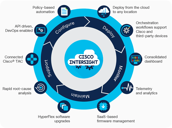
Cisco Intersight is a lifecycle management platform for your infrastructure, regardless of where it resides. In your enterprise data center, at the edge, in remote and branch offices, at retail and industrial sites—all these locations present unique management challenges and have typically required separate tools. Cisco Intersight Software as a Service (SaaS) unifies and simplifies your experience of the Cisco Unified Computing System (Cisco UCS). See Figure 7.
The Cisco UCS Fabric Interconnect (FI) is a core part of the Cisco Unified Computing System, providing both network connectivity and management capabilities for the system. Depending on the model chosen, the Cisco UCS Fabric Interconnect offers line-rate, low-latency, lossless 10/25/40/100 Gigabit Ethernet, Fibre Channel over Ethernet (FCoE) and Fibre Channel connectivity. Cisco UCS Fabric Interconnects provide the management and communication backbone for the Cisco UCS C-Series, B-Series and X-Series Blade Servers, and 9508 Series Blade Server Chassis. All servers and chassis, and therefore all blades, attached to the Cisco UCS Fabric Interconnects become part of a single, highly available management domain. In addition, by supporting unified fabrics, the Cisco UCS Fabric Interconnects provide both the LAN and SAN connectivity for all servers within its domain.
The Cisco UCS 6536 36-Port Fabric Interconnect (Figure 8) is a One-Rack-Unit (1RU) 10/25/40/100 Gigabit Ethernet, FCoE, and Fibre Channel switch offering up to 7.42 Tbps throughput and up to 36 ports. The switch has 32 40/100-Gbps Ethernet ports and 4 unified ports that can support 40/100-Gbps Ethernet ports or 16 Fiber Channel ports after break-out at 8/16/32-Gbps FC speeds. The 16 FC ports after breakout can either operate as an FC uplink port or as an FC storage port. The switch supports 2 1-Gbps speed after breakout and all 36 ports can breakout for 10/25-Gbps Ethernet connectivity. All Ethernet ports are capable of supporting FCoE.

Cisco UCS C-Series Rack-Mount Servers
Cisco UCS C-Series Rack-Mount Servers keep pace with Intel Xeon processor innovation by offering the latest processors with increased processor frequency and improved security and availability features. With the increased performance provided by the Intel Xeon Scalable Family Processors, Cisco UCS C-Series servers offer an improved price-to-performance ratio. They also extend Cisco UCS innovations to an industry-standard rack-mount form factor, including a standards-based unified network fabric, Cisco VN-Link virtualization support, and Cisco Extended Memory Technology.
It is designed to operate both in standalone environments and as part of Cisco UCS managed configuration, these servers enable organizations to deploy systems incrementally—using as many or as few servers as needed—on a schedule that best meets the organization’s timing and budget. Cisco UCS C-Series servers offer investment protection through the capability to deploy them either as standalone servers or as part of Cisco UCS. One compelling reason that many organizations prefer rack-mount servers is the wide range of I/O options available in the form of PCIe adapters. Cisco UCS C-Series servers support a broad range of I/O options, including interfaces supported by Cisco and adapters from third parties.
Cisco UCS C240 M7 Rack-Mount Server
The Cisco UCS C240 M7 Rack Server extends the capabilities of the Cisco UCS rack server portfolio with up to two 4th or 5th Gen Intel Xeon Scalable CPUs, with up to 60 cores per socket. The maximum memory capacity for 2 CPUs is 4 TB (32 x 128 GB DDR5 4800/5600 MT/s DIMMs). The Cisco UCS C240 M7 has a 2-Rack-Unit (RU) form and supports up to 8 PCIe 4.0 slots or up to 4 PCIe 5.0 slots plus a modular LAN on motherboard (mLOM) slot. Up to three double-wide (full height full length FHFL) or eight single-wide (half height half length HHHL) GPUs are supported. The server delivers significant performance and efficiency gains that will improve your application performance.
For more details, go to: Cisco UCS C240 M7 Rack Server Data Sheet.
Cisco UCS X-Series Modular System
The Cisco UCS X-Series is a modular system, engineered to be adaptable and future ready. It is a standard, open system designed to deploy and automate faster in concert with your hybrid cloud environment. It is designed to meet the needs of modern applications and improve operational efficiency, agility, and scale through an adaptable, future-ready, modular design.
Designed to deploy and automate hybrid cloud environments:
● Simplify with cloud-operated infrastructure
● Simplify with an adaptable system designed for modern applications
● Simplify with a system engineered for the future
For more details, go to: https://www.cisco.com/c/dam/en/us/products/collateral/servers-unified-computing/ucs-x-series-modular-system/x9508-specsheet.pdf
Cisco UCS X210c Compute Node
The Cisco UCS X210c M7 Compute Node is the computing device to integrate into the Cisco UCS X-Series Modular System. Up to eight compute nodes can reside in the 7-Rack-Unit (7RU) Cisco UCS X9508 Chassis, offering one of the highest densities of compute, IO, and storage per rack unit in the industry. It reduces the number of server types to maintain, helping to improve operational efficiency and agility as it helps reduce complexity. Powered by the Cisco Intersight™ cloud operations platform, it shifts your thinking from administrative details to business outcomes with hybrid cloud infrastructure that is assembled from the cloud, shaped to your workloads, and continuously optimized
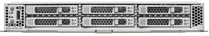
A unified fabric interconnects all devices in the system. It securely carries all traffic to the fabric interconnects where it can be broken out into IP networking, Fibre Channel SAN, and management connectivity.
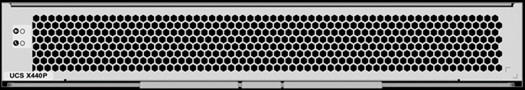
Cisco UCS X440p PCIe Node
The Cisco UCS X440p PCIe Node is the first PCIe resource node to integrate into the Cisco UCS X-Series Modular System. The Cisco UCS X9508 Chassis has eight node slots, up to four of which can be X440p PCIe nodes when paired with a Cisco UCS X210c Compute Node. The Cisco UCS X440p PCIe Node supports two x16 full-height full-length (FHFL) dual slot PCIe cards, or four x8 half-height half-length (HHHL) single slot PCIe cards and requires both Cisco UCS 9416 X-Fabric modules for PCIe connectivity. This provides up to 16 GPUs per chassis to accelerate your applications with the Cisco UCS X440p Nodes. If your application needs even more GPU acceleration, up to two additional GPUs can be added on each Cisco UCS X210c compute node.
Benefits include:
● Accelerate more workloads with up to four GPUs
● Make it easy to add, update, and remove GPUs to Cisco UCS X210c M7 Compute Nodes
● Get a zero-cable solution for improved reliability and ease of installation
● Have industry standard PCIe Gen 4 connections for compatibility
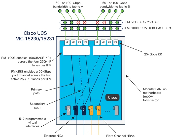
Cisco UCS Virtual Interface Cards
The Cisco UCS Virtual Interface Card (VIC) extends the network fabric directly to both servers and virtual machines so that a single connectivity mechanism can be used to connect both physical and virtual servers with the same level of visibility and control. Cisco® VICs provide complete programmability of the Cisco UCS I/O infrastructure, with the number and type of I/O interfaces configurable on demand with a zero-touch model.
Cisco VICs support Cisco SingleConnect technology, which provides an easy, intelligent, and efficient way to connect and manage computing in your data center. Cisco SingleConnect unifies LAN, SAN, and systems management into one simplified link for rack servers, blade servers, and virtual machines. This technology reduces the number of network adapters, cables, and switches needed and radically simplifies the network, reducing complexity. Cisco VICs can support 512 PCI Express (PCIe) virtual devices, either virtual network interface cards (vNICs) or virtual Host Bus Adapters (vHBAs), with a high rate of I/O operations per second (IOPS), support for lossless Ethernet, and 10/25/50/100/200-Gbps connection to servers. The PCIe Generation 4 x16 interface helps ensure optimal bandwidth to the host for network-intensive applications, with a redundant path to the fabric interconnect. Cisco VICs support NIC teaming with fabric failover for increased reliability and availability. In addition, it provides a policy-based, stateless, agile server infrastructure for your data center.
For more details, go to: https://www.cisco.com/c/en/us/products/interfaces-modules/unified-computing-system-adapters/index.html
Cisco Intersight is Cisco’s systems management platform that delivers intuitive computing through cloud-powered intelligence. This platform offers a more intelligent level of management that enables IT organizations to analyze, simplify, and automate their environments in ways that were not possible with prior generations of tools. This capability empowers organizations to achieve significant savings in Total Cost of Ownership (TCO) and to deliver applications faster, so they can support new business initiatives.
Cisco Intersight offers flexible deployment either as Software as a Service (SaaS) on Intersight.com or running on your premises with the Cisco Intersight virtual appliance. The virtual appliance provides users with the benefits of Cisco Intersight while allowing more flexibility for those with additional data locality and security requirements.
● Define desired system configurations based on policies that use pools of resources provided by the Cisco UCS X-Series. Let Cisco Intersight assemble the components and set up everything from firmware levels to which I/O devices are connected. Infrastructure is code, so your IT organization can use the Cisco Intersight GUI, and your DevOps teams can use the Intersight API, the Intersight Service for HashiCorp Terraform, or the many API bindings from languages such as Python and PowerShell.
● Deploy from the cloud to any location. Anywhere the cloud reaches, Cisco Intersight can automate your IT processes. We take the guesswork out of implementing new services with a curated set of services we bundle with the Intersight Kubernetes Service, for example.
● Visualize the interdependencies between software components and how they use the infrastructure that supports them with Intersight Workload Optimizer.
● Optimize your workload by analyzing runtime performance and make resource adjustments and workload placements to keep response time within a desired range. If your first attempt at matching resources to workloads doesn’t deliver the results you need, you can reshape the system quickly and easily. Cisco Intersight facilitates deploying workloads into your private cloud and into the public cloud. Now one framework bridges your core, cloud, and edge infrastructure, managing infrastructure and workloads wherever they are deployed.
● Maintain your infrastructure with a consolidated dashboard of infrastructure components regardless of location. Ongoing telemetry and analytics give early detection of possible failures. Reduce risk of configuration drift and inconsistent configurations through automation with global policy enforcement.
● Support your infrastructure with AI-driven root-cause analysis and automated case support for the always-connected Cisco Technical Assistance Center (Cisco TAC). Intersight watches over you when you update your solution stack, helping to prevent incompatible hardware, firmware, operating system, and hypervisor configurations.
Cisco Intersight provides the following features for ease of operations and administration for the IT staff:
● Connected TAC
● Security Advisories
● Hardware Compatibility List (HCL)
To learn more about all the features of Cisco Intersight, go to: https://www.cisco.com/c/en/us/products/servers-unified-computing/intersight/index.html
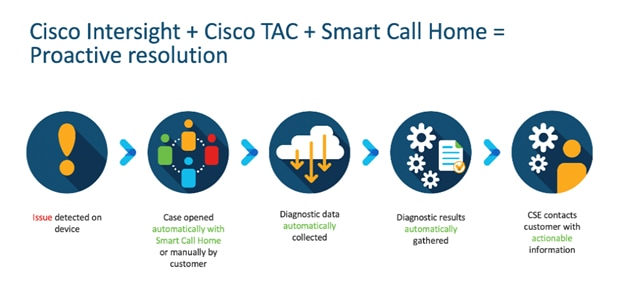
Connected TAC is an automated transmission of technical support files to the Cisco Technical Assistance Center (TAC) for accelerated troubleshooting.
Cisco Intersight enables Cisco TAC to automatically generate and upload Tech Support Diagnostic files when a Service Request is opened. If you have devices that are connected to Intersight but not claimed, Cisco TAC can only check the connection status and will not be permitted to generate Tech Support files. When enabled, this feature works in conjunction with the Smart Call Home service and with an appropriate service contract. Devices that are configured with Smart Call Home and claimed in Intersight can use Smart Call Home to open a Service Request and have Intersight collect Tech Support diagnostic files.
Procedure 1. Enable Connected TAC
Step 1. Log into Intersight.com.
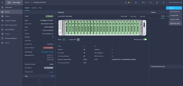
Step 2. Click the Servers tab. Go to Server > Actions tab. From the drop-down list, click Open TAC Case.
Step 3. Click Open TAC Case to launch the Cisco URL for the support case manager where associated service contracts for Server or Fabric Interconnect is displayed.
Step 4. Click Continue.
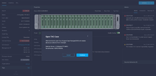
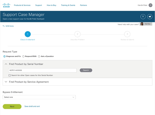
Step 5. Follow the procedure to Open TAC Case.
Cisco Intersight Integration for HCL
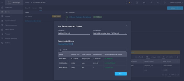
Cisco Intersight evaluates the compatibility of your Cisco UCS and HyperFlex systems to check if the hardware and software have been tested and validated by Cisco or Cisco partners. Cisco Intersight reports validation issues after checking the compatibility of the server model, processor, firmware, adapters, operating system, and drivers, and displays the compliance status with the Hardware Compatibility List (HCL).
You can use Cisco UCS Tools, a host utility vSphere Installation Bundle (VIB), or OS Discovery Tool, an open-source script to collect OS and driver information to evaluate HCL compliance.
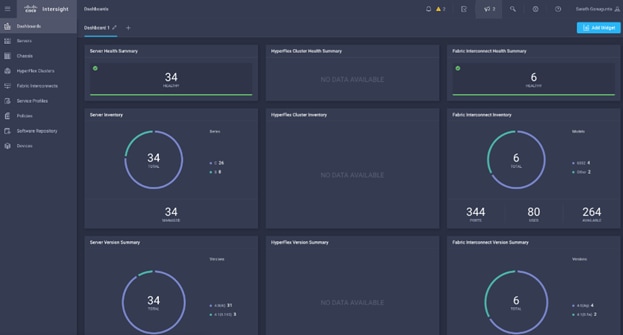
In Cisco Intersight, you can view the HCL compliance status in the dashboard (as a widget), the Servers table view, and the Server details page.
For more information, go to: https://www.intersight.com/help/features#compliance_with_hardware_compatibility_list_(hcl)
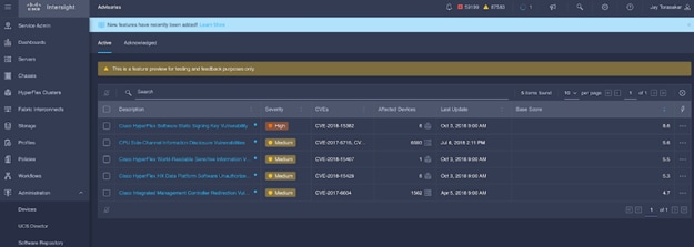
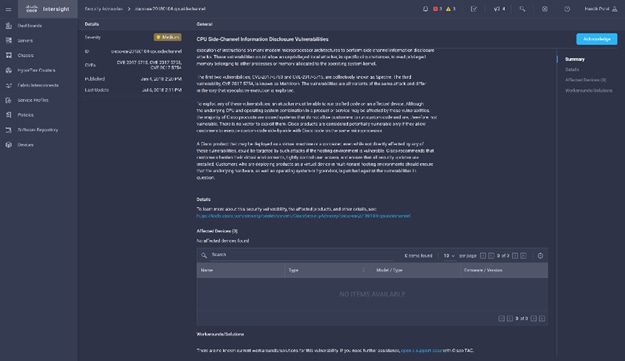
Cisco Intersight sources critical security advisories from the Cisco Security Advisory service to alert users about the endpoint devices that are impacted by the advisories and deferrals. These alerts are displayed as Advisories in Intersight. The Cisco Security Advisory service identifies and monitors and updates the status of the advisories to provide the latest information on the impacted devices, the severity of the advisory, the impacted products, and any available workarounds. If there are no known workarounds, you can open a support case with Cisco TAC for further assistance. A list of the security advisories is shown in Intersight under Advisories.
Cloudera Data Platform Private Cloud (CDP Private Cloud) is the on-premises version of Cloudera Data Platform. CDP Private Cloud delivers powerful analytic, transactional, and machine learning workloads in a hybrid data platform, combining the agility and flexibility of public cloud with the control of the data center. With a choice of traditional as well as elastic analytics and scalable object storage, CDP Private Cloud modernizes traditional monolithic cluster deployments into a powerful and efficient platform.
An integral part of CDP Hybrid Cloud, CDP Private Cloud provides the first step for data center customers toward true data and workload mobility, managed from a single pane of glass and with consistent data security and governance across all clouds, public and private.
With CDP Private Cloud, organizations benefit from:
● Unified Distribution: CDP offers rapid time to value through simplified provisioning of easy-to-use, self-service analytics enabling onboarding of new use cases at higher velocity.
● Hybrid and On-prem: Hybrid and multi-cloud experience, on-prem it offers best performance, cost, and security. It is designed for data centers with optimal infrastructure.
● Management: It provides consistent management and control points for deployments.
● Consistency: Security and governance policies can be configured once and applied across all data and workloads.
● Portability: Policies stickiness with data, even if it moves across all supported infrastructure.
● Improved cost efficiency with optimized resource utilization and the decoupling of compute and storage, lowering data center infrastructure costs up to 50%.
● Predictable performance thanks to workload isolation and perfectly managed multi-tenancy, eliminating the impact of spikes on critical workloads and resulting missed SLAs and SLOs.
Cloudera is integrating NVIDIA NIM and CUDA-X microservices to Cloudera Machine Learning to deliver powerful generative AI capabilities and performance. This integration will empower enterprises to make more accurate and timely decisions while also mitigating inaccuracies, hallucinations, and errors in predictions — all critical factors for navigating today’s data landscape. To learn more about Cloudera Enterprise AI go to: https://www.cloudera.com/why-cloudera/enterprise-ai.html
Cloudera Data Platform Private Cloud Base (CDP Private Cloud Base)
CDP Private Cloud Base is the on-premises version of Cloudera Data Platform. This new product combines the best of Cloudera Enterprise Data Hub and Hortonworks Data Platform Enterprise along with new features and enhancements across the stack. This unified distribution is a scalable and customizable platform where you can securely run many types of workloads.
CDP Private Cloud Base supports a variety of hybrid solutions where compute tasks are separated from data storage and where data can be accessed from remote clusters, including workloads created using CDP Private Cloud Data Services. This hybrid approach provides a foundation for containerized applications by managing storage, table schema, authentication, authorization, and governance.
CDP Private Cloud Base is comprised of a variety of components such as Apache HDFS, Apache Hive, Apache HBase, and Apache Impala, along with many other components for specialized workloads. You can select any combination of these services to create clusters that address your business requirements and workloads. Several pre-configured packages of services are also available for common workloads.
Cloudera Data Platform Private Cloud Data Services (CDP Private Cloud DS)
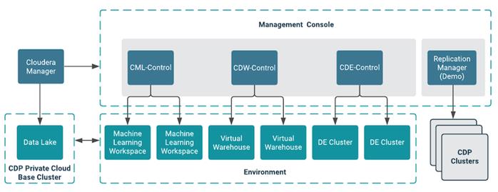
Cloudera Data Platform (CDP) Private Cloud (Figure 21) is the newest on-prem offering of CDP that brings many of the benefits of the public cloud deployments to the on-prem CDP deployments.
CDP Private Cloud provides a disaggregation of compute and storage and allows independent scaling of compute and storage clusters. Using containerized applications deployed on Kubernetes, CDP Private Cloud brings both agility and predictable performance to analytic applications. CDP Private Cloud gets unified security, governance, and metadata management through Cloudera Shared Data Experience (SDX), which is available on a CDP Private Cloud Base cluster.
CDP Private Cloud users can rapidly provision and deploy Cloudera Data Engineering (CDE), Cloudera Data Warehousing (CDW) and Cloudera Machine Learning (CML) services through the Management Console, and easily scale them up or down as required.
A CDP Private Cloud deployment requires you to have a Private Cloud Base cluster and a RedHat OpenShift Kubernetes cluster. The OpenShift cluster is set up on a Bare Metal deployment. The Private Cloud deployment process involves configuring the Management Console on the OpenShift cluster, registering an environment by providing details of the Data Lake configured on the Base cluster, and then creating the workloads.
Benefits of CDP Private Cloud Data Services
● Simplified multitenancy and isolation
The containerized deployment of applications in CDP Private Cloud ensures that each application is sufficiently isolated and can run independently from others on the same Kubernetes infrastructure, to eliminate resource contention. Such a deployment also helps in independently upgrading applications based on your requirements. In addition, all these applications can share a common Data Lake instance.
● Simplified deployment of applications
CDP Private Cloud ensures a much faster deployment of applications with a shared Data Lake compared to monolithic clusters where separate copies of security and governance data would be required for each separate application. In situations where you need to provision applications on an arbitrary basis, for example, to deploy test applications or to allow for self-service, transient workloads without administrative or operations overhead, CDP Private Cloud enables you to rapidly perform such deployments.
● Better utilization of infrastructure
CDP Private Cloud enables resource provisioning in real time when deploying applications. In addition, the ability to scale or suspend applications on a need basis ensures that on-premises infrastructure is utilized optimally.
Cloudera Shared Data Experience (SDX)
SDX is a fundamental part of Cloudera Data Platform architecture, unlike other vendors’ bolt-on approaches to security and governance. Independent from compute and storage layers, SDX delivers an integrated set of security and governance technologies built on metadata and delivers persistent context across all analytics as well as public and private clouds. Consistent data context simplifies the delivery of data and analytics with a multi-tenant data access model that is defined once and seamlessly applied everywhere.
SDX reduces risk and operational costs by delivering consistent data context across deployments. IT can deploy fully secured and governed data lakes faster, giving more users access to more data, without compromise.
Key benefit and feature of SDX includes:
● Insightful metadata - Trusted, reusable data assets and efficient deployments need more than just technical and structural metadata. CDP’s Data Catalog provides a single pane of glass to administer and discover all data, profiled, and enhanced with rich metadata that includes the operational, social, and business context, and turns data into valuable information.
● Powerful security - Eliminate business and security risks and ensure compliance by preventing unauthorized access to sensitive or restricted data across the platform with full auditing. SDX enables organizations to establish multi-tenant data access with ease through standardization and seamless enforcement of granular, dynamic, role- and attribute-based security policies on all clouds and data centers.
● Full encryption - Enjoy ultimate protection as a fundamental part of your CDP installation. Clusters are deployed and automatically configured to use Kerberos and for encrypted network traffic with Auto-TLS. Data at rest, both on-premises and in the cloud, is protected with enterprise-grade cryptography, supporting best practice tried and tested configurations.
● Hybrid control - Meet the ever-changing business needs to balance performance, cost, and resilience. Deliver true infrastructure independence. SDX enables it all with the ability to move data, together with its context, as well as workloads between CDP deployments. Platform operational insight into aspects like workload performance deliver intelligent recommendations for optimal resource utilization.
● Enterprise-grade governance - Prove compliance and manage the complete data lifecycle from the edge to AI and from ingestion to purge with data management across all analytics and deployments. Identify and manage sensitive data, and effectively address regulatory requirements with unified, platform-wide operations, including data classification, lineage, and modeling.
CDP Private Cloud Management Console
The Management Console is a service used by CDP administrators to manage environments, users, and services.
The Management Console allows you to:
● Enable user access to CDP Private Cloud Data Services, onboard and set up authentication for users, and determine access rights for the various users to the available resources.
● Register an environment, which represents the association of your user account with compute resources using which you can manage and provision workloads such as Data Warehouse and Machine Learning. When registering the environment, you must specify a Data Lake residing on the Private Cloud base cluster to provide security and governance for the workloads.
● View information about the resources consumed by the workloads for an environment.
● Collect diagnostic information from the services for troubleshooting purposes.
Figure 22 shows a basic architectural overview of the CDP Private Cloud Management Console.
Apache Ozone
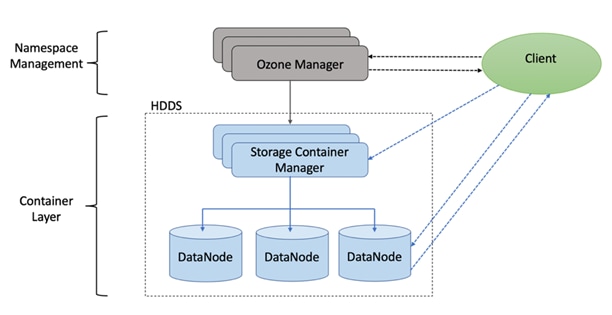
Apache Ozone is a scalable, redundant, and distributed object store for Hadoop. Apart from scaling to billions of objects of varying sizes, Ozone can function effectively in containerized environments such as Kubernetes and YARN. Applications using frameworks like Apache Spark, YARN, and Hive work natively without any modifications. Ozone is built on a highly available, replicated block storage layer called Hadoop Distributed Data Store (HDDS).
Ozone is a scale-out architecture with minimal operational overheads and long-term maintenance efforts. Ozone can be co-located with HDFS with single security and governance policies for easy data exchange or migration and also offers seamless application portability. Ozone enables separation of compute and storage via the S3 API as well as similar to HDFS, it also supports data locality for applications that choose to use it.
Apache Ozone is a scalable, redundant, and distributed object store. Apart from scaling to billions of objects of varying sizes, Ozone can function effectively in containerized environments such as Kubernetes and YARN. Applications using frameworks like Apache Spark, YARN, and Hive work natively without any modifications. Apache Ozone is built on a highly available, replicated block storage layer called Hadoop Distributed Data Store (HDDS).
Apache Ozone consists of volumes, buckets, and keys:
● Volumes are similar to user accounts. Only administrators can create or delete volumes.
● Buckets are similar to directories. A bucket can contain any number of keys, but buckets cannot contain other buckets.
● Keys are similar to files. Each key is part of a bucket, which, in turn, belongs to a volume. Ozone stores data as keys inside these buckets.
When a key is written to Apache Ozone, the associated data is stored on the Data Nodes in chunks called blocks. Therefore, each key is associated with one or more blocks. Within the Data Nodes, a series of unrelated blocks is stored in a container, allowing many blocks to be managed as a single entity.
Apache Ozone separates management of namespaces and storage, helping it to scale effectively. Apache Ozone Manager manages the namespaces while Storage Container Manager handles the containers.
Apache Ozone is a distributed key-value store that can manage both small and large files alike. While HDFS provides POSIX-like semantics, Apache Ozone looks and behaves like an Object Store.
Apache Ozone has the following cost savings and benefits due to storage consolidation:
● Lower Infrastructure cost
● Lower software licensing and support cost
● Lower lab footprint
● Newer additional use cases with support for HDFS and S3 and billions of objects supporting both large and small files in a similar fashion.
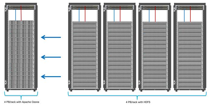
For more information about Apache Ozone, go to: https://blog.cloudera.com/apache-ozone-and-dense-data-nodes/
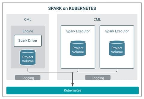
Apache Spark 3.0
Apache Spark 3.0 delivered many new capabilities, performance gains, and extended compatibility for the Spark ecosystem such as accelerator-aware scheduling, adaptive query execution, dynamic partition pruning, join hints, new query explain, better ANSI compliance, observable metrics, new UI for structured streaming, new UDAF and built-in functions, new unified interface for Pandas UDF, and various enhancements in the built-in data sources.
Apache Spark 3.0's enhancements in container support and GPU acceleration provide significant benefits in terms of deployment flexibility, resource utilization, and performance. These features empower users to leverage containerized environments and GPUs to accelerate data processing workflows and achieve better scalability and efficiency. For more information, see: Cisco Blog on Apache Spark 3.0
Cloudera Machine Learning (CML)
Cloudera Machine Learning (CML) is a comprehensive platform designed to simply the process of build, train, deploy and manage machine learning and AI capabilities for business at scale, efficiently and securely. Cloudera Machine Learning on Private Cloud is built for the agility and power of cloud computing but operates inside your private and secure data center.
Unified Data Platform: Cloudera Machine Learning integrates with Cloudera Data Platform (CDP), providing a unified data platform that enables data engineers, data scientists, and data analysts to work collaboratively on data-driven projects.
Collaborative Environment: CML offers a collaborative environment where teams can work together on data science projects. It provides features like version control, shared notebooks, and collaboration tools to enhance productivity.
Data Access and Management: CML allows users to access and manage data from various sources including Hadoop Distributed File System (HDFS), Apache Hive, Apache HBase, and cloud storage services.
Model Development and Training: Data scientists can leverage CML's integrated Jupyter notebooks to develop and prototype machine learning models using popular libraries such as TensorFlow, PyTorch, scikit-learn, and Spark MLlib.
Model Versioning and Experiment Tracking: CML enables versioning of machine learning models and tracking of experiments, making it easier to reproduce results and track the performance of different model iterations.
Scalability and Performance: CML is built on Cloudera's enterprise-grade infrastructure, allowing users to scale their machine learning workloads as needed. It supports distributed computing frameworks like Apache Spark for handling large datasets and complex computations.
Model Deployment: Once models are trained and validated, CML facilitates the deployment of models into production environments. It provides options for deploying models as REST APIs or batch inference jobs, allowing seamless integration with existing applications.
Monitoring and Management: CML includes monitoring and management capabilities to track the performance of deployed models in real-time, monitor resource utilization, and ensure the reliability and scalability of deployed applications.
Security and Governance: Security is a key focus of CML, with features such as role-based access control (RBAC), encryption, and integration with enterprise security systems to ensure data privacy and compliance with regulatory requirements.
Integration with Ecosystem Tools: CML integrates with a wide range of ecosystem tools and services, including Cloudera Data Warehouse, Cloudera Data Flow, and third-party tools like Git, Jenkins, and Kubernetes.
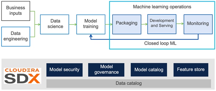
As shown in Figure 26, an end-to-end production workflow in Cloudera Machine Learning (CML) encompasses the entire AI/ML life-cycle, from data preparation to model deployment and monitoring.
This chapter contains the following:
This CVD was designed with the following:
● Cisco Intersight managed Cisco UCS C240 M7 Rack Server with two NVIDIA H100/L40S/A100 GPU Installed per node
● Cloudera Data Platform Private Cloud Base 7.1.9
● Cloudera Data Platform Data Services 1.5.3
Table 3 lists the required physical components and hardware.
Table 3. CDIP with CDP Private Cloud hardware Components
| Component |
Hardware |
| Fabric Interconnects |
2 x Cisco UCS 6536 Fabric Interconnects |
| Servers |
3 x Cisco UCS C220 M7 (admin node – CDP Private Cloud Base) 8 x Cisco UCS C240 M7 (data node/worker node – CDP Private Cloud Base) 3 x Cisco UCS C220 M7 (ECS mgmt. node - CDP Private Cloud Data Services) 4 x C240 M7/X210c M7 w/ NVIDIA GPU (ECS worker node - CDP Private Cloud Data Services) |
Software Components
Table 4 lists the software components and the versions required for a single cluster of the Cohesity Helios Platform running in Cisco UCS, as tested, and validated in this document.
Table 4. Software Distributions and Firmware Versions
| Layer |
Component |
Version or Release |
| Compute |
Cisco UCS C240 M7 rack server |
4.3(3.240022) |
| Cisco UCS X210c M7 compute node |
5.2(0.230092) |
|
| Network
|
Cisco UCS Fabric Interconnect 6536 (Intersight mode) |
4.3(2.240002) |
| Cisco UCS VIC 15238 |
5.3(2.46) |
|
| Cisco UCS VIC 15231 |
5.3(2.40) |
|
| Software |
Cloudera Manager |
7.11.3 |
| Cloudera Private Cloud Base |
7.1.9 |
|
| Cloudera Private Cloud Data Services |
1.5.3 |
|
| CDP Parcel |
7.1.9-1.cdh7.1.9.p0.44702451 |
|
| Spark3 |
3.3.2.3.3.7190.0-91 CDS |
|
| Postgres |
14.11 |
|
| Hadoop (Includes YARN and HDFS) |
3.1.1.7.1.9.0-387 |
|
| Spark2 |
2.4.8.7.1.9.0-387 |
|
| Ozone |
1.3.0.7.1.9.0-387 |
|
| Red Hat Enterprise Linux Server |
9.1 |
The Cisco latest drivers can be downloaded here: https://software.cisco.com/download/home.
Refer to the Cisco UCS HCL for recommendation on server firmware, OS support and driver version, here: https://ucshcltool.cloudapps.cisco.com/public/
Check the CDP Private Cloud requirements and supported versions for information about hardware, operating system, and database requirements, as well as product compatibility matrices, here: https://supportmatrix.cloudera.com/ and here: https://docs.cloudera.com/cdp-private-cloud-upgrade/latest/release-guide/topics/cdpdc-requirements-supported-versions.html
For Cloudera Private Cloud Base and Experiences versions and supported features, go to: https://docs.cloudera.com/cdp-private-cloud-base/7.1.9/runtime-release-notes/topics/rt-pvc-runtime-component-versions.html
For Cloudera Private Cloud Base requirements and supported version, go to: https://docs.cloudera.com/cdp-private-cloud-base/7.1.9/installation/topics/cdpdc-requirements-supported-versions.html
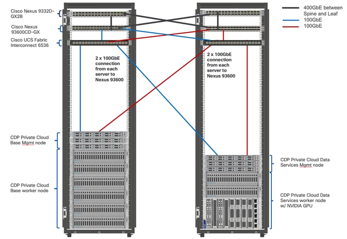
Physical Topology
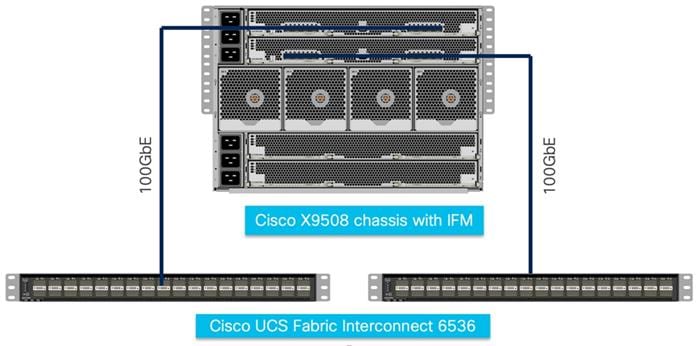
Two rack consists of two vertical PDUs per rack and two Cisco UCS Fabric Interconnect with 6 x Cisco UCS C220 M7, 10 x Cisco UCS C240 M7 Rack Servers and Cisco UCS X9508 chassis with 100G IFM and Cisco UCS X210c M7 node with NVIDIA GPU installed in X440p PCIe node installed and cabled as illustrated in Figure 27. 100Gigabit Ethernet link from each rack server and IFM connected to both Fabric Interconnects. (Port 0 connected to FI - A and port 1 connected to FI – B).
Note: Contact your Cisco representative for country-specific information.
Note: X440p PCIe node based GPU installation requires Cisco UCS 9416 X-Fabric module (UCSX-F-9416) for Cisco UCS 9508 chassis and Cisco UCS PCI Mezz Card (UCSX-V4-PCIME) for Cisco UCS X210c M7 compute node. Review the spec sheet for the Cisco UCS X9508 chassis and Cisco UCS X210c M7 compute node for more details.
Note: Dedicated NVMe drives are recommended to store ozone metadata and ozone mgmt. configuration for the admin/mgmt. nodes and worker/data nodes.
Note: The minimum starter configuration is 3 master/admin nodes for HA (high availability) and 9 data/worker Nodes. This will support erasure coding rs(6,3) if intended to enable erasure coding. Additional nodes can be added to increase storage and/or compute for CDP Private Cloud cluster.
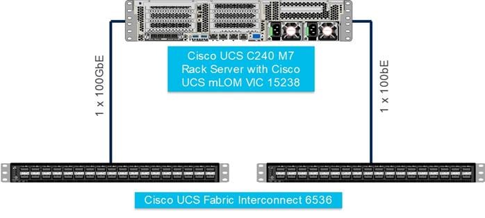
Figure 28 and Figure 29 show the logical topology for server connection.
Cisco UCS Install and Configure
This chapter contains the following:
This section details the Cisco Intersight deployed Cisco UCS C240 M7 rack server connected to Cisco UCS Fabric Interconnect 64108 as part of the infrastructure build out. The racking, power, and installation of the Cisco UCS Rack Server for Cloudera Private Cloud Base can be found at Cisco Data Intelligence Platform Design Zone page. For detailed installation information, refer to the Cisco Intersight Managed Mode Configuration Guide.
Install Cisco UCS
This section contains the following procedures:
● Claim a Cisco UCS Fabric Interconnect in the Cisco Intersight Platform
● Configure Cisco Intersight Pools and Policies
● Configure UCS Domain Policies
● Create Cisco Intersight Policy
● Create Ethernet Adapter Policy
● Derive and Deploy the Server Profiles
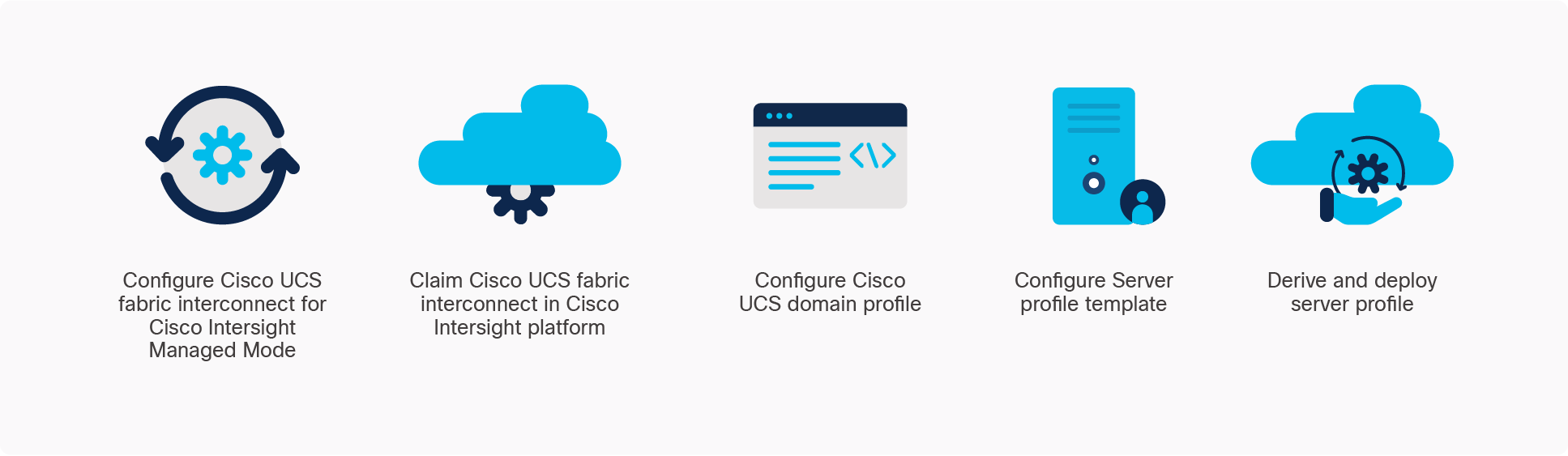
Cisco Intersight Managed Mode standardizes policy and operation management for Cisco UCS X-Series. The compute nodes in Cisco UCS X-Series are configured using server profiles defined in Cisco Intersight. These server profiles derive all the server characteristics from various policies and templates. At a high level, configuring Cisco UCS using Intersight Managed Mode consists of the steps shown in Figure 30.
See the Initial Configuration section of the Cisco UCS Manager Getting Started Guide, Release 4.3, for more details about setting up Cisco UCS Fabric Interconnect.
Procedure 1. Claim a Cisco UCS Fabric Interconnect in the Cisco Intersight Platform
Note: After setting up the Cisco UCS fabric interconnect for Cisco Intersight Managed Mode, FIs can be claimed to a new or an existing Cisco Intersight account. When a Cisco UCS fabric interconnect is successfully added to the Cisco Intersight platform, all subsequent configuration steps are completed in the Cisco Intersight portal.
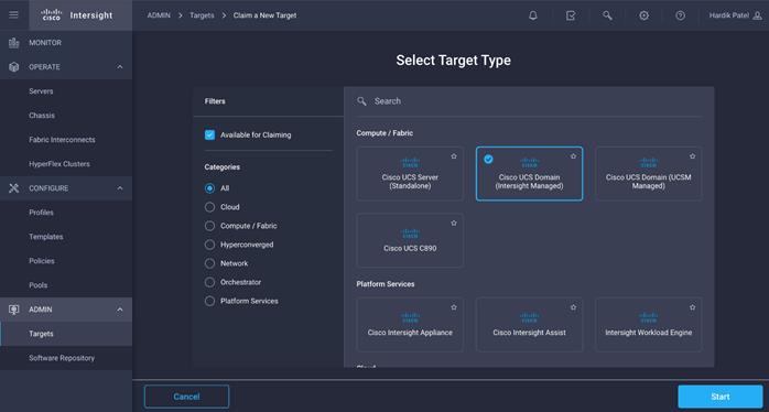
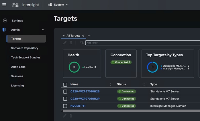
Step 1. To claim FI in IMM node, go to Targets > Claim a New Target.
Step 2. Select Cisco UCS Domain (Intersight Managed).
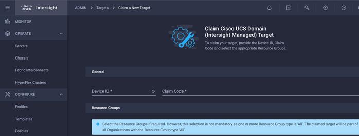
Step 3. Enter Device ID and Claim Code from one of the FI to be claimed. Click Claim.
Step 4. Review the newly claimed Cisco UCS Domain.
For more information, go to: https://intersight.com/help/saas/getting_started/claim_targets
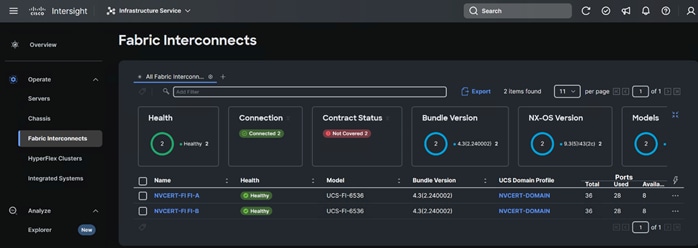
Step 5. Cisco UCS fabric interconnect in OPERATE tab shows details and Management Mode as shown below:
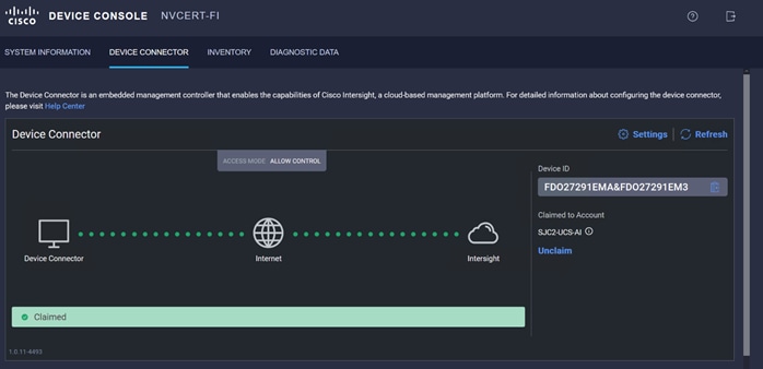
Step 6. Cisco UCS fabric interconnect Device Console WebUI > Device Connector tab shows claimed account name as shown below:
Procedure 2. Configure Cisco Intersight account settings
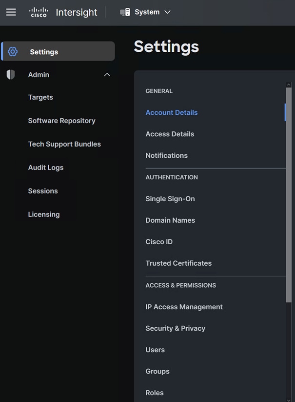
Step 1. To configure or display account specific parameters or edit license subscription; go to System > Admin. For more details: https://intersight.com/help/saas/system/settings
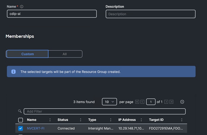
Step 2. In access & Permissions section, select Resource Group. Create New resource group.
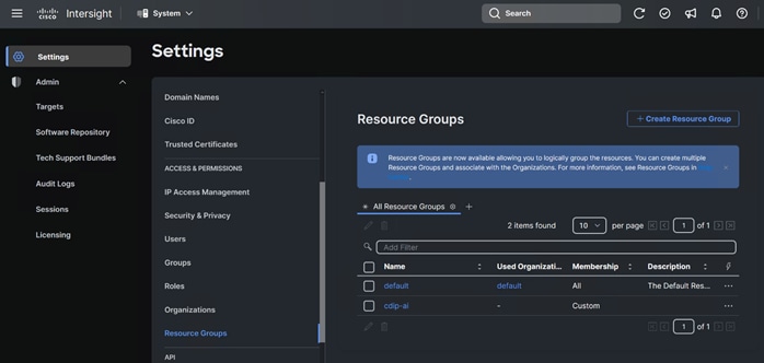
Step 3. Select Target to be part of the resource group and click Create.
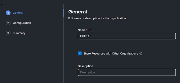
Step 4. In access & Permissions section, select Organizations then click Create Organization
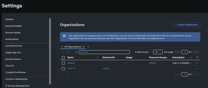
Step 5. Enter the details for the new Organization creation. (Optional) Check the box to share resources with other organizations. Click Next.
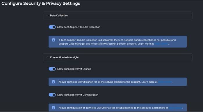
Step 6. In Security & Privacy settings click Configure to enable allow Tunneled vKVM Launch and configuration. Click Save.
Procedure 3. Configure Cisco Intersight Pools, Policies, and Profiles
Note: Cisco Intersight requires different pools and policies which can be created at the time of profile creation or can be pre-populated and attached to the profile.
Step 1. To create the required set of pools, go to Configure > Pools. Click Create Pool.
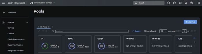
Step 2. Select one of the pool type creations and provide a range for the pool creation.
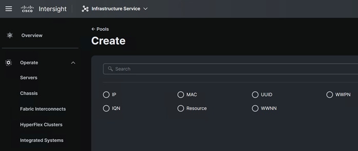
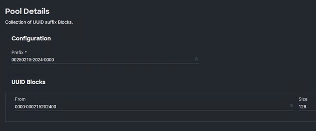
Step 3. Select UUID and click Create. Enter name for UUID pool.
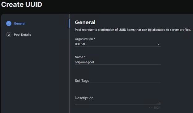
Step 4. Enter the Prefix and range for UUID block.
Step 5. Follow the steps to create IP Pool to access vKVM, MAC pool, Resource Pool.
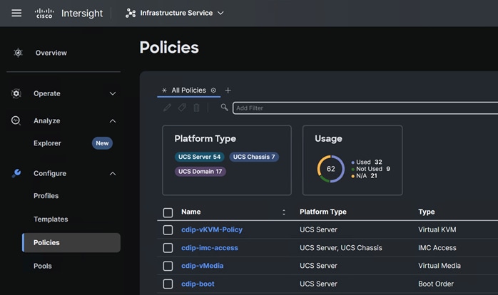
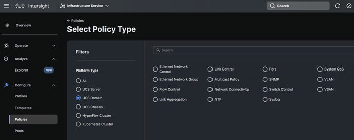
Step 6. To create the required set of policies, go to Configure > Policies. Click Create Policy.
Cisco UCS Domain Profile
A Cisco UCS domain profile configures a pair of fabric interconnect through reusable policies, allows configuration of the ports and port channels, and configures the VLANs to be used in the network. It defines the characteristics of and configures the ports on the fabric interconnects. One Cisco UCS domain profile can be assigned to one fabric interconnect domain, and the Cisco Intersight platform supports the attachment of one port policy per Cisco UCS domain profile.
Some of the characteristics of the Cisco UCS domain profile environment are:
● A single domain profile is created for the pair of Cisco UCS fabric interconnects.
● Unique port policies are defined for the two fabric interconnects.
● The VLAN configuration policy is common to the fabric interconnect pair because both fabric interconnects are configured for same set of VLANs.
● The Network Time Protocol (NTP), network connectivity, and system Quality-of-Service (QoS) policies are common to the fabric interconnect pair.
After the Cisco UCS domain profile has been successfully created and deployed, the policies including the port policies are pushed to Cisco UCS fabric interconnects. Cisco UCS domain profile can easily be cloned to install additional Cisco UCS systems. When cloning the UCS domain profile, the new UCS domains utilize the existing policies for consistent deployment of additional UCS systems at scale.
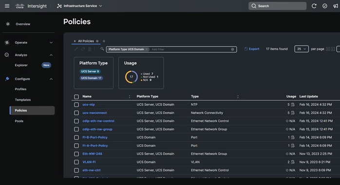
Procedure 1. Configure UCS Domain Policies
Step 1. Create policies for UCS Domain which will be applied to fabric interconnects.
Step 2. Go to Configure > Profiles. Click Create UCS Domain Profile.
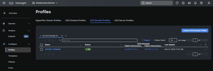
Step 3. Click Start.
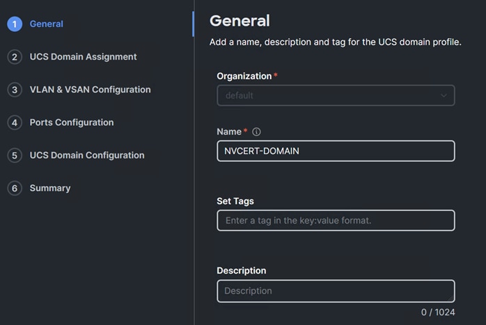
Step 4. Select organization, add name, description, and tag for the UCS Domain Profile.
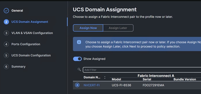
Step 5. Select UCS Domain to assign UCS Domain Profile.
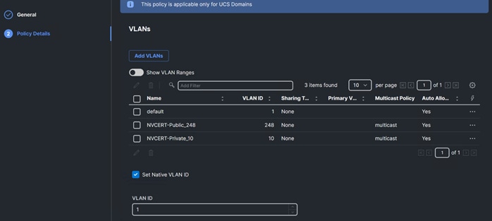
Step 6. Select the policy for the VLAN and VSAN configuration as applicable.
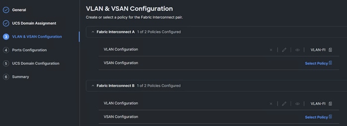
Step 7. A sample VLAN policy configuration is shown below. Configure the VLAN policy as required for your environment.
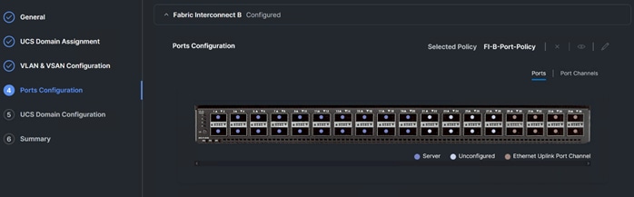
Step 8. Select Ports Configuration for FI – A and FI – B.
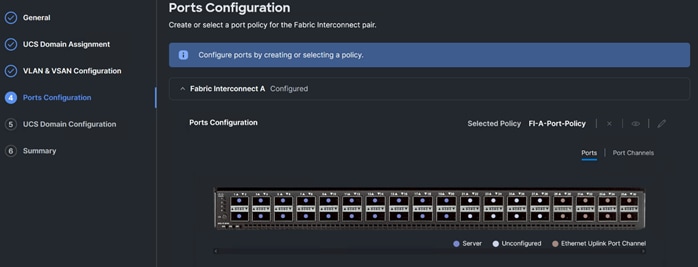
Step 9. Port Configuration policy creation allows you to configure port roles based on the requirement such as Server ports, uplink port, Port channel configuration, Unified ports, and breakout options.
Step 10. Create Port role as Server for ports connected to Cisco UCS servers.
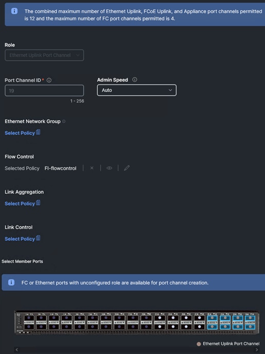
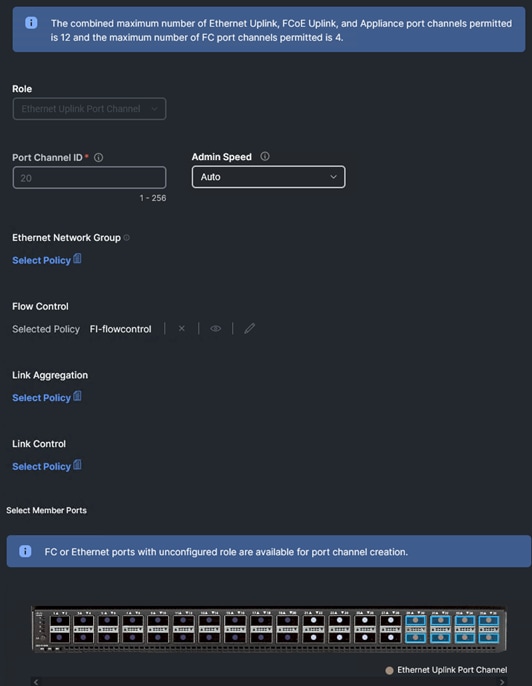
Step 11. Create Ethernet Uplink Port Channel for ports connected to pair of Nexus 9000 switch. Create or assign policies to attach with Ethernet Uplink Port Channel.
● Flow Control
● Link Aggregation
● Link Control
● Ethernet Network Group
Note: The Ethernet Network Group Policy specifies a set of VLANs to allow on the uplink port. The specified VLAN set must be either identical or disjoint from those specified on other uplink interfaces. Ensure that the VLANs are defined in the VLAN Policy, and 'Auto Allow on Uplinks' option is disabled. the default VLAN-1 is auto allowed and can be specified as the native VLAN.
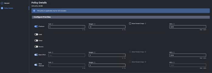
Step 12. Select the compute and management policies to be associated with the fabric interconnects in UCS Domain configuration.
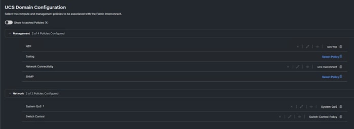
The System QoS policy with the following configuration was deployed:
Step 13. Review the Domain profile summary. Click Deploy.
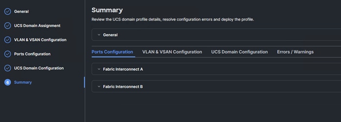
Step 14. After a successful deployment of the domain profile chassis, the server discovery will start according to the connection between Cisco UCS hardware.
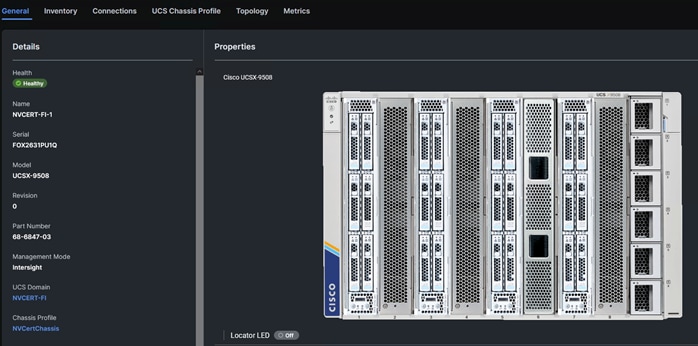
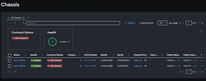
Cisco UCS Chassis Profile
The Cisco UCS X9508 Chassis and Cisco UCS X210c M7 Compute Nodes are automatically discovered when the ports are successfully configured using the domain profile, as shown in the following figures.
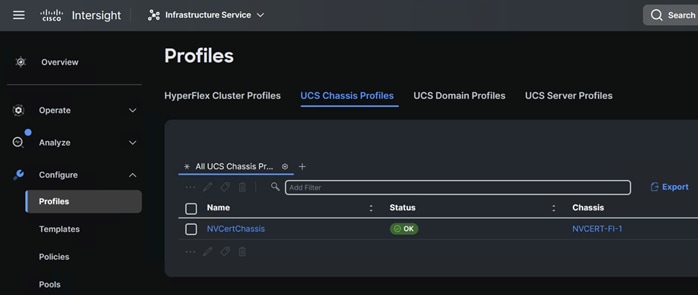
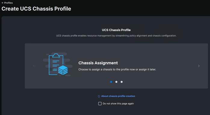
Procedure 1. Create UCS Chassis Profile
Step 1. To create UCS Chassis profile, go to Configure > Profiles > UCS Chassis Profiles. Click Create UCS Chassis Profile.
Step 2. Click Start.
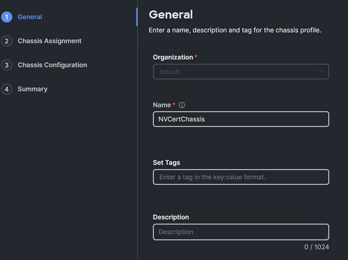
Step 3. Select organization, enter name, tags, and description for the UCS Chassis profile.
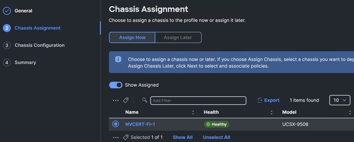
Step 4. Select chassis assignment.
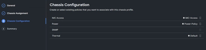
Step 5. Select chassis configuration policies.
Step 6. Review the chassis profile summary.
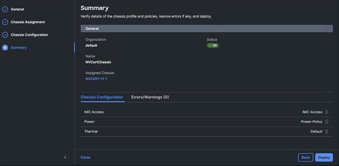
Step 7. Click Deploy Chassis Profile.
Cisco UCS Server Profile
In Cisco Intersight, a Server Profile enables resource management by streamlining policy alignment, and server configuration. After creating Server Profiles, you can edit, clone, deploy, attach to a template, create a template, detach from template, or unassign them as required. From the Server Profiles table view, you can select a profile to view details in the Server Profiles Details view.
Procedure 1. Create Cisco BIOS Policy
Step 1. Go to Configure > Policies > Create Policy.
Step 2. Select policy type as BIOS.
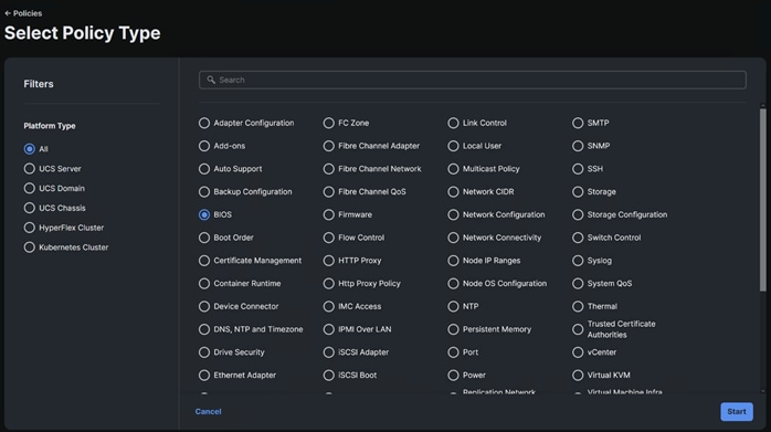
Step 3. Add a name, description, and tag for the BIOS Policy. Click Next.
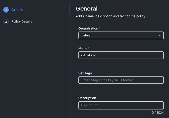
Step 4. Edit BIOS options by click the + sign and edit required value for each of the BIOS settings. A sample BIOS configuration is shown below:
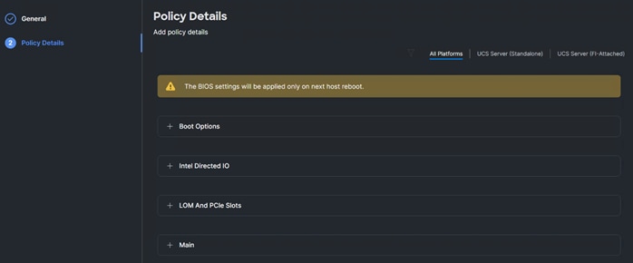
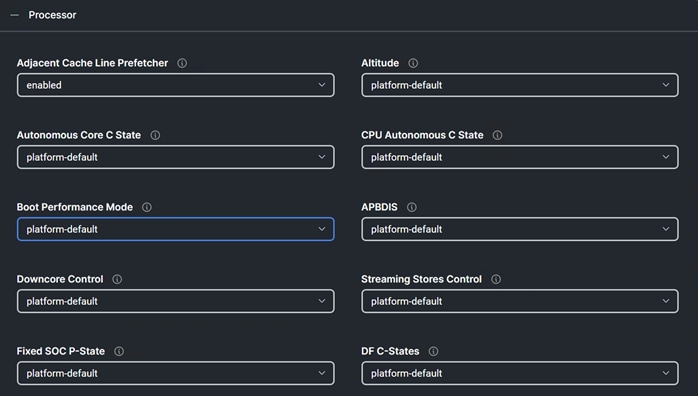
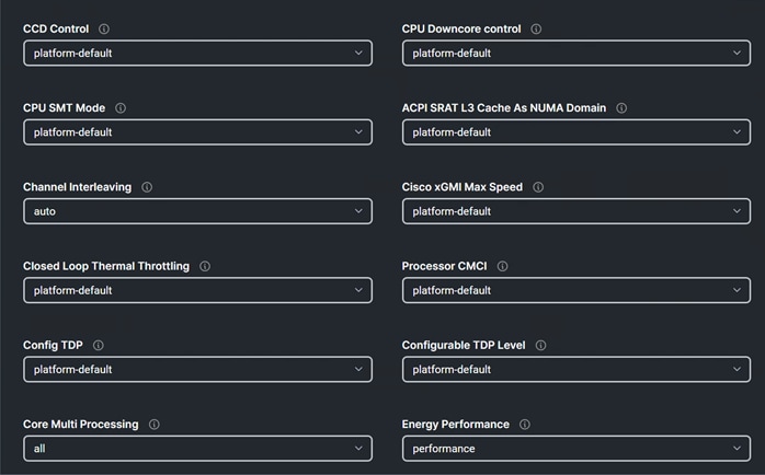
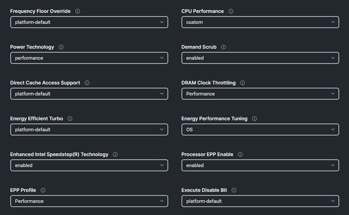
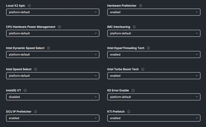
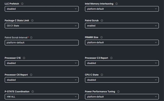
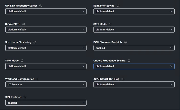
Note: BIOS settings can have a significant performance impact, depending on the workload and the applications. The BIOS settings listed in this section is for configurations optimized for best performance which can be adjusted based on the application, performance, and energy efficiency requirements.
For more information, go to: Performance Tuning Guide.
Procedure 2. Create Boot Order Policy
Step 1. Go to Configure > Policies > Create Policy.
Step 2. Select the policy type as Boot Order.
Step 3. Add a name, description, and tag for the Boot Order policy. Click Next.
Step 4. Configure UEFI Boot Mode with Enable Secure Boot. Enable Local Disk with M.2 drive installed in “MSTOR-RAID” slot and CIMC Mapped DVD. Additional boot devices can be added, or boot order can be adjusted as required.
Note: UEFI Boot Mode with Enable Secure Boot required Trusted Execution Technology (TXT) Support Enabled in BIOS policy.
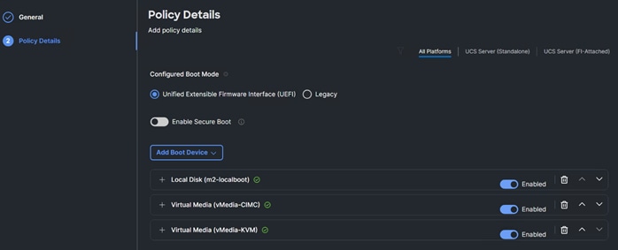
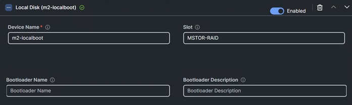
Procedure 3. Create Virtual Media Policy
Step 1. Go to Configure > Policies > Create Policy.
Step 2. Select the policy type as Virtual Media.
Step 3. Enter a name for vMedia Policy.
Step 4. Click Add Virtual Media. Select Virtual Media Type and protocol. Enter the required field value.
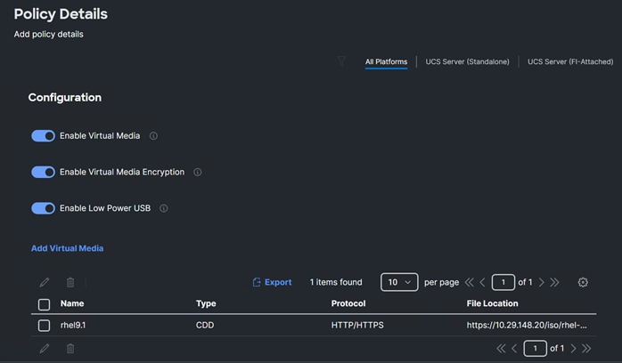
Procedure 4. Create IMC Access Policy
Step 1. Go to Configure > Policies > Create Policy.
Step 2. Select the policy type as IMC Access.
Step 3. Enable In-Band or Out-Of-Band Configuration and select IP Pool to assign as range of IP address for Virtual KVM access.
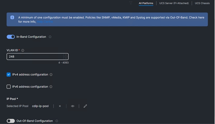
Procedure 5. Create Virtual KVM Policy
Step 1. Go to Configure > Policies > Create Policy.
Step 2. Select the policy type as Virtual KVM.
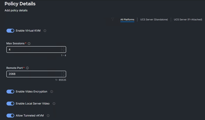
Procedure 6. Create Storage Policy
Step 1. Go to Configure > Policies > Create Policy.
Step 2. Select the policy type as Storage.
Step 3. Enter a name for the storage policy.
Step 4. Enable JBOD drives for virtual drive creation, select state of the unused drive. Enable configuration for M.2 RAID configuration, MRAID/RAID Controller configuration or MRAID/RAID Single Drive RAID0 Configuration as applicable.
Step 5. Enable M.2 configuration and select Slot of the M.2 RAID controller for virtual drive creation as “MSTOR-RAID-1 (MSTOR-RAID).”
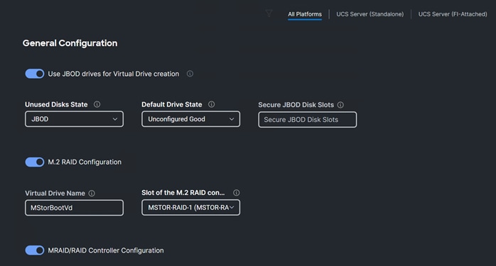
Step 6. Enter the details for data node/storage node configuration according to disk slot populated in the server. Please refer to the server inventory > storage controllers > RAID controller > Physical Drives for disk slot details.
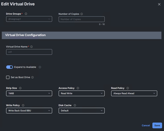
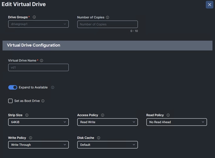
Step 7. Create the storage policy for master/mgmt node:
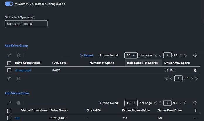
Procedure 7. Create Ethernet Adapter Policy
Step 1. Go to Configure > Policies > Create Policy.
Step 2. Select the policy type as Ethernet Adapter.
Step 3. Add the policy details as follows:
◦ Interrupts – 70
◦ Receive Queue Count – 64
◦ Receive Ring Size - 16384
◦ Transmit Queue Count – 8
◦ Transmit Ring Size – 16384
◦ Completion Queue Count – 72
◦ Receive Side Scaling - Enabled
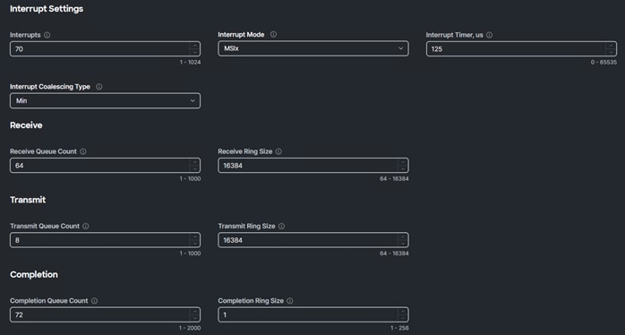
Procedure 8. Create Ethernet QoS Policy
Step 1. Go to Configure > Policies > Create Ehternet QoS.
Step 2. Enter a policy name.
Step 3. Configure MTU 9000 and Rate Limit as 100000 Mbps for 100G network adapter, Class of Service as 5 to match with priority as platinum.
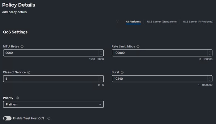
Procedure 9. Create LAN Connect Policy
Step 1. Go to Configure > Policies > Create Policy.
Step 2. Select the policy type as LAN Connectivity.
Step 3. Enter a policy name and select Target Platform as UCS Server (FI-Attached).
Step 4. Click Add vNIC.
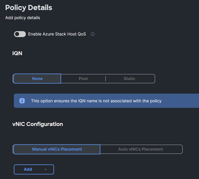
Step 5. Enter or select an existing policy for vNIC creation (the screenshot shows placement with mLOM Cisco UCS VIC 1467):
◦ vNIC name
◦ select MAC Pool
◦ Placement
◦ Consistent Device Naming (CDN)
◦ Failover – Enabled
◦ Ethernet Network Group Policy
◦ Ethernet Network Control Policy
◦ Ethernet QoS
◦ Ethernet Adapter
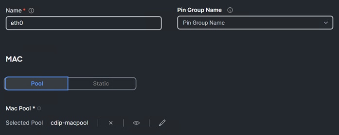
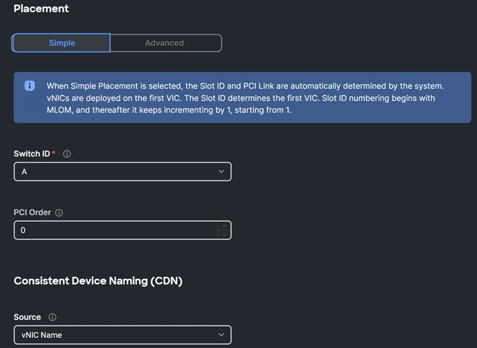
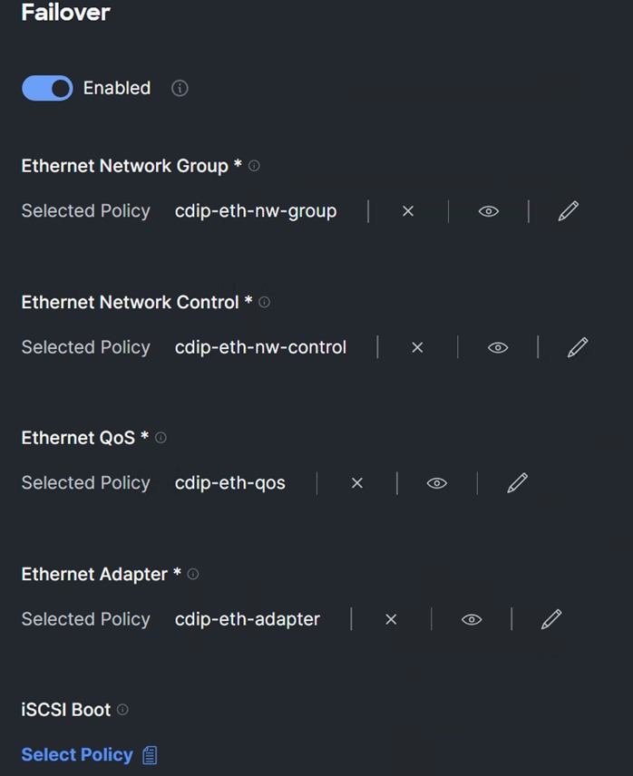
Server Profile Template
A server profile template enables resource management by simplifying policy alignment and server configuration. A server profile template is created using the server profile template wizard. The server profile template wizard groups the server policies into the following four categories to provide a quick summary view of the policies that are attached to a profile:
Derive and Deploy Server Profiles from the Cisco Intersight Server Profile Template
The Cisco Intersight server profile allows server configurations to be deployed directly on the server based on polices defined in the server profile template. After a server profile template has been successfully created, server profiles can be derived from the template and associated with the Cisco UCS Servers as shown in Figure 42.
Procedure 1. Derive and Deploy the Server Profiles
Step 1. Go to Configure > Templates > Select existing Server Profile Template. Click Derive Profiles.
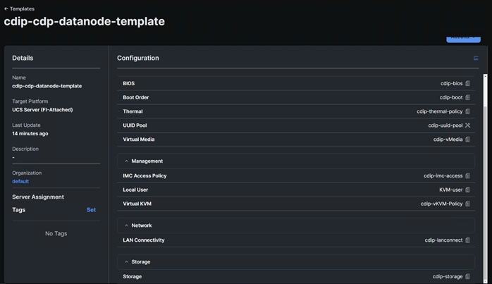
Step 2. Select Server Assignment to derive profiles from template. Select Assign Now, Assign Server from a Resource Pool or Assign Later.
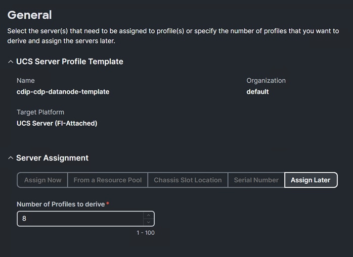
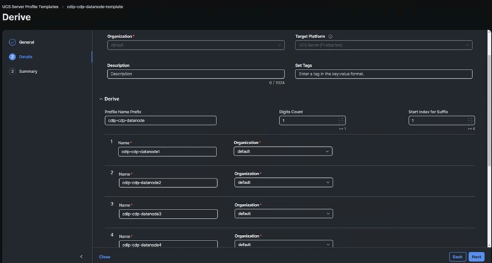
Step 3. Review Derive Profile from the template. Click Derive.
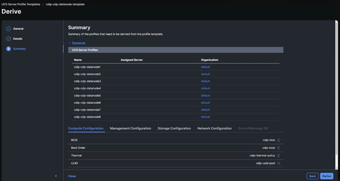
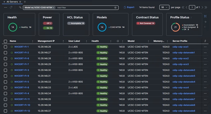
Install Red Hat Enterprise Linux 9.1
This chapter contains the following:
● Install Red Hat Enterprise Linux (RHEL) 9.1
This chapter provides detailed procedures for installing Red Hat Enterprise Linux Server using Software RAID (OS based Mirroring) on Cisco UCS C240 M5 servers. There are multiple ways to install the RHEL operating system. The installation procedure described in this deployment guide uses KVM console and virtual media from Cisco UCS Manager.
Note: In this study, Red Hat Enterprise Linux version 9.1 DVD/ISO was utilized for OS the installation via CIMC mapped vMedia on Cisco UCS C240 M7 Rack Server.
Install Red Hat Enterprise Linux (RHEL) 9.1
Procedure 1. Install Red Hat Enterprise Linux 9.1
Step 1. Log into Cisco Intersight.
Step 2. Select THE server(s) to install operating system. Select Installation Operating System.
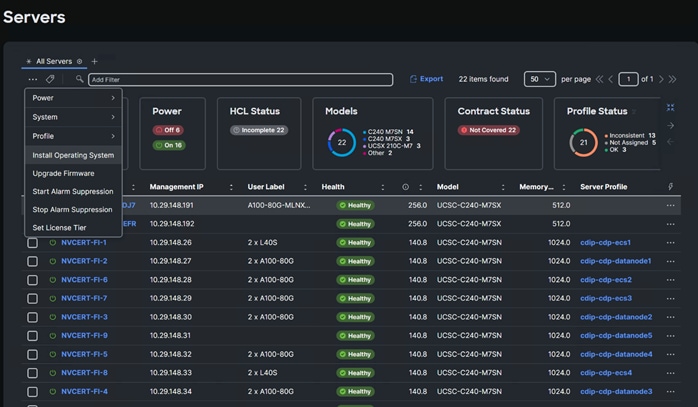
Step 3. Review the system selected for Operating system installation.
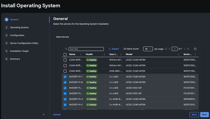
Step 4. Select OS image or click Add OS Image Link to add the OS to be installed.
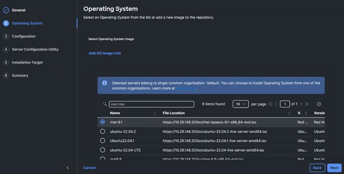
Step 5. Enter the OS configuration details, click Next.
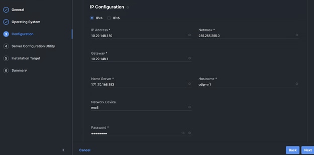
Step 6. Select the SCU image.
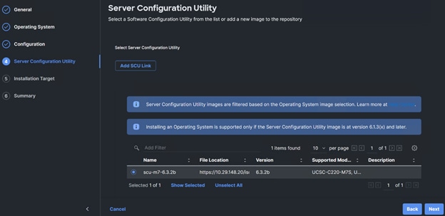
Step 7. Select Installation Target.
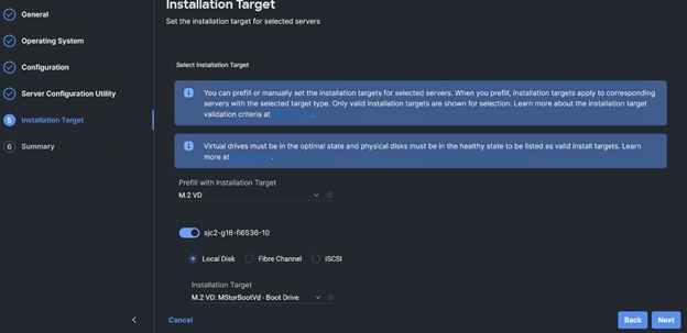
Step 8. (Optional) the manual installation of OS can be performed through virtual KVM console. Go to Operate > Servers > click the ellipses and select Launch vKVM or Tunneled vKVM.
Step 9. From the virtual KVM console check Virtual Media tab for the image in use. Click Continue the Welcome screen for RHEL 9.1 installation.
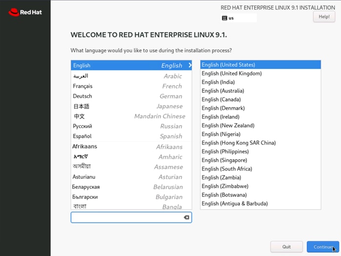
Step 10. Select Time & Date.
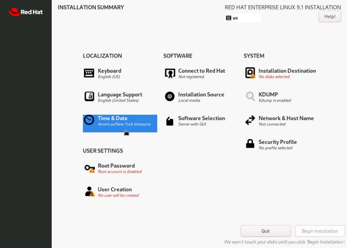
Step 11. Select Region and City.
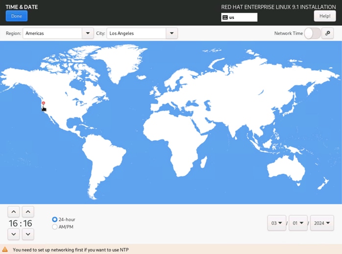
Step 12. Select Software Selection. Select “Server for the Bare Environment” and add the required software:
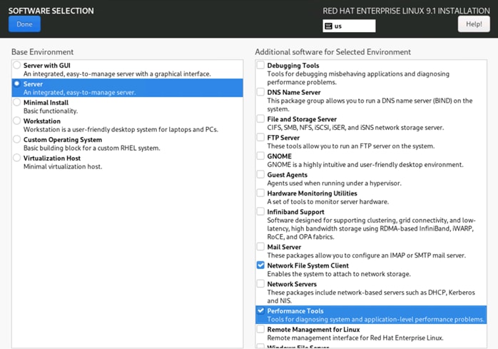
Step 13. Click Installation Destination > select storage device ATA CISCO VD (M.2 Hardware RAID controller provisioned RAID 1 virtual disk). Select Custom storage configuration. Click Done.
Step 14. Click the + sign to add new mount point. Click Done after creating the new mount points as follows:
◦ /boot/efi
◦ /boot
◦ Swap
◦ /
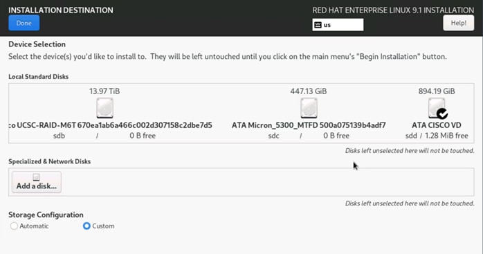
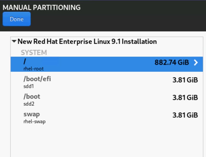
Step 15. Click Accept Changes.
Step 16. Select Network & Host Name. Enter host name and configure network adapter with static IP address.
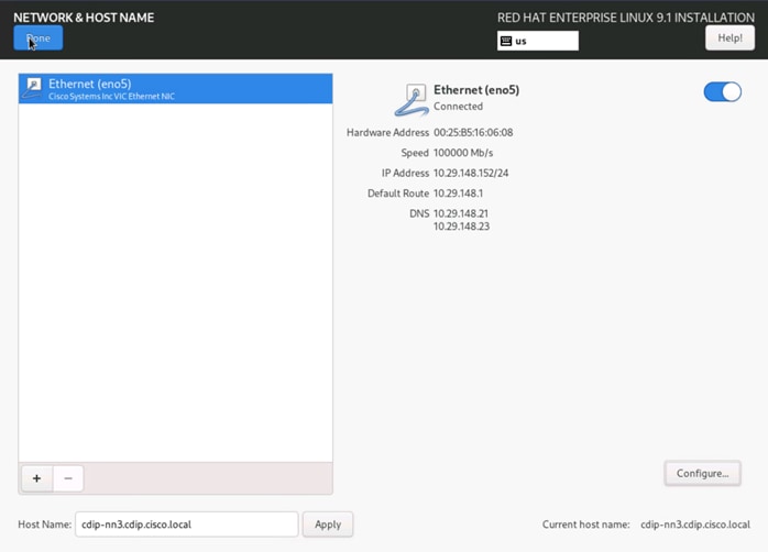
Step 17. Select Root Password. Enter the root password and confirm.
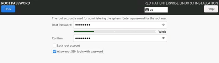
Step 18. Click Begin Installation.
Step 19. Reboot after successful OS installation.
Choose one of the nodes of the cluster or a separate node as the Admin Node for management, such as CDP DC installation, Ansible, creating a local Red Hat repo, and others.
Note: In this document, we configured cdip-nn1 for this purpose.
Procedure 1. Configure /etc/hosts
Step 1. Setup /etc/hosts on the Admin node; this is a pre-configuration to setup DNS as shown in the next section.
Note: For the purpose of simplicity, /etc/hosts file is configured with hostnames in all the nodes. However, in large scale production grade deployment, DNS server setup is highly recommended.
Step 2. To create the host file on the admin node, log into the Admin Node (cdip-nn1).
# ssh 10.29.148.150
Step 3. Populate the host file with IP addresses and corresponding hostnames on the Admin node (cdip-nn1) and other nodes as follows:
vi /etc/hosts
10.29.148.150 cdip-nn1.cdip.cisco.local cdip-nn1
10.29.148.151 cdip-nn2.cdip.cisco.local cdip-nn2
10.29.148.152 cdip-nn3.cdip.cisco.local cdip-nn3
10.29.148.153 cdip-dsms1.cdip.cisco.local cdip-dsms1
10.29.148.154 cdip-dsms2.cdip.cisco.local cdip-dsms2
10.29.148.155 cdip-dsms3.cdip.cisco.local cdip-dsms3
10.29.148.156 cdip-dn1.cdip.cisco.local cdip-dn1
10.29.148.157 cdip-dn2.cdip.cisco.local cdip-dn2
10.29.148.158 cdip-dn3.cdip.cisco.local cdip-dn3
10.29.148.159 cdip-dn4.cdip.cisco.local cdip-dn4
10.29.148.160 cdip-dn5.cdip.cisco.local cdip-dn5
10.29.148.161 cdip-dn6.cdip.cisco.local cdip-dn6
10.29.148.162 cdip-dn7.cdip.cisco.local cdip-dn7
10.29.148.163 cdip-dn8.cdip.cisco.local cdip-dn8
10.29.148.164 cdip-ecs1.cdip.cisco.local cdip-ecs1
10.29.148.165 cdip-ecs2.cdip.cisco.local cdip-ecs2
10.29.148.166 cdip-ecs3.cdip.cisco.local cdip-ecs3
10.29.148.167 cdip-ecs4.cdip.cisco.local cdip-ecs4
Procedure 2. Set Up Password-less Login
To manage all the nodes in a cluster from the admin node, password-less login needs to be setup. It assists in automating common tasks with Ansible, and shell-scripts without having to use passwords.
Enable the passwordless login across all the nodes when Red Hat Linux is installed across all the nodes in the cluster.
Step 1. Log into the Admin Node (cdip-nn1).
# ssh 10.29.148.150
Step 2. Run the ssh-keygen command to create both public and private keys on the admin node.
# ssh-keygen -N '' -f ~/.ssh/id_rsa
Step 3. Run the following command from the admin node to copy the public key id_rsa.pub to all the nodes of the cluster. ssh-copy-id appends the keys to the remote-hosts .ssh/authorized_keys.
# for i in {1..3}; do echo "copying cdip-nn$i.cdip.cisco.local"; ssh-copy-id -i ~/.ssh/id_rsa.pub root@cdip-nn$i.cdip.cisco.local; done;
# for i in {1..8}; do echo "copying cdip-dn$i.cdip.cisco.local"; ssh-copy-id -i ~/.ssh/id_rsa.pub root@cdip-dn$i.cdip.cisco.local; done;
# for i in {1..3}; do echo "copying cdip-dsms$i.cdip.cisco.local"; ssh-copy-id -i ~/.ssh/id_rsa.pub root@cdip-dsms$i.cdip.cisco.local; done;
# for i in {1..4}; do echo "copying cdip-ecs$i.cdip.cisco.local"; ssh-copy-id -i ~/.ssh/id_rsa.pub root@cdip-ecs$i.cdip.cisco.local; done;
Step 4. Enter yes for Are you sure you want to continue connecting (yes/no)?
Step 5. Enter the password of the remote host.
Step 6. Enable RHEL subscription and install EPEL
# sudo subscription-manager register –username <password> --password <password> --auto-attach
# sudo subscription-manager repos --enable codeready-builder-for-rhel-9-$(arch)-rpms
# sudo dnf install https://dl.fedoraproject.org/pub/epel/epel-release-latest-9.noarch.rpm -y
Procedure 3. Create a Red Hat Enterprise Linux (RHEL) 9.1 Local Repository
To create a repository using RHEL DVD or ISO on the admin node, create a directory with all the required RPMs, run the “createrepo” command and then publish the resulting repository.
Note: Based on this repository file, yum requires httpd to be running on cdip-nn1 for other nodes to access the repository.
Note: This step is required to install software on Admin Node (cdip-nn1) using the repo (such as httpd, create-repo, and so on.)
Step 1. Log into cdip-nn1.
Step 2. Copy RHEL 9.1 iso from remote repository.
# scp rhel-baseos-9.1-x86_64-dvd.iso cdip-nn1:/root/
Step 3. Create a directory that would contain the repository.
# mkdir -p /var/www/html/rhelrepo
Step 4. Create mount point to mount RHEL ISO
# mkdir -p /mnt/rheliso
# mount -t iso9660 -o loop /root/rhel-baseos-9.1-x86_64-dvd.iso /mnt/rheliso/
Step 5. Copy the contents of the RHEL 9.1 ISO to /var/www/html/rhelrepo
# cp -r /mnt/rheliso/* /var/www/html/rhelrepo
Step 6. Create a .repo file to enable the use of the yum command on cdip-nn1
# vi /var/www/html/rhelrepo/rheliso.repo
[rhel9.1]
name= Red Hat Enterprise Linux 9.1
baseurl=http://10.29.148.150/rhelrepo/BaseOS/
gpgcheck=0
enabled=1
Step 7. Copy the rheliso.repo file from /var/www/html/rhelrepo to /etc/yum.repos.d on cdip-nn1.
# cp /var/www/html/rhelrepo/rheliso.repo /etc/yum.repos.d/
Step 8. To make use of repository files on cdip-nn1 without httpd, edit the baseurl of repo file /etc/yum.repos.d/rheliso.repo to point repository location in the file system.
# vi /etc/yum.repos.d/rheliso.repo
[rhel9.1]
name=Red Hat Enterprise Linux 9.1
baseurl=file:///var/www/html/rhelrepo/BaseOS/
gpgcheck=0
enabled=1
Procedure 4. Create the Red Hat Repository Database
Step 1. Install the createrepo package on admin node (cdip-nn1). Use it to regenerate the repository database(s) for the local copy of the RHEL DVD contents.
# dnf install -y createrepo
Step 2. Run createrepo on the RHEL repository to create the repo database on admin node.
# cd /var/www/html/rhelrepo/BaseOS/
# createrepo .
Procedure 5. Set up Ansible
Step 1. Install ansible-core
# dnf install -y ansible-core ansible
# # ansible --version
ansible [core 2.14.9]
config file = /etc/ansible/ansible.cfg
configured module search path = ['/root/.ansible/plugins/modules', '/usr/share/ansible/plugins/modules']
ansible python module location = /usr/lib/python3.9/site-packages/ansible
ansible collection location = /root/.ansible/collections:/usr/share/ansible/collections
executable location = /usr/bin/ansible
python version = 3.9.14 (main, Sep 21 2022, 00:00:00) [GCC 11.3.1 20220421 (Red Hat 11.3.1-2)] (/usr/bin/python3)
jinja version = 3.1.2
libyaml = True
Step 2. Prepare the host inventory file for Ansible as shown below. Various host groups have been created based on any specific installation requirements of certain hosts.
# vi /etc/ansible/hosts
[admin]
cdip-nn1.cdip.cisco.local
[namenodes]
cdip-nn1.cdip.cisco.local
cdip-nn2.cdip.cisco.local
cdip-nn3.cdip.cisco.local
[datanodes]
cdip-dn1.cdip.cisco.local
cdip-dn2.cdip.cisco.local
cdip-dn3.cdip.cisco.local
cdip-dn4.cdip.cisco.local
cdip-dn5.cdip.cisco.local
cdip-dn6.cdip.cisco.local
cdip-dn7.cdip.cisco.local
cdip-dn8.cdip.cisco.local
[dsmasternodes]
cdip-dsms1.cdip.cisco.local
cdip-dsms2.cdip.cisco.local
cdip-dsms3.cdip.cisco.local
[ecsnodes]
cdip-ecs1.cdip.cisco.local
cdip-ecs2.cdip.cisco.local
cdip-ecs3.cdip.cisco.local
cdip-ecs4.cdip.cisco.local
[nodes]
cdip-nn1.cdip.cisco.local
cdip-nn2.cdip.cisco.local
cdip-nn3.cdip.cisco.local
cdip-dn1.cdip.cisco.local
cdip-dn2.cdip.cisco.local
cdip-dn3.cdip.cisco.local
cdip-dn4.cdip.cisco.local
cdip-dn5.cdip.cisco.local
cdip-dn6.cdip.cisco.local
cdip-dn7.cdip.cisco.local
cdip-dn8.cdip.cisco.local
cdip-ecs1.cdip.cisco.local
cdip-ecs2.cdip.cisco.local
cdip-ecs3.cdip.cisco.local
cdip-ecs4.cdip.cisco.local
cdip-dsms1.cdip.cisco.local
cdip-dsms2.cdip.cisco.local
cdip-dsms3.cdip.cisco.local
Step 3. Verify host group by running the following commands.
# ansible namenodes -m ping
cdip-nn3.cdip.cisco.local | SUCCESS => {
"ansible_facts": {
"discovered_interpreter_python": "/usr/libexec/platform-python"
},
"changed": false,
"ping": "pong"
}
cdip-nn2.cdip.cisco.local | SUCCESS => {
"ansible_facts": {
"discovered_interpreter_python": "/usr/libexec/platform-python"
},
"changed": false,
"ping": "pong"
}
cdip-nn1.cdip.cisco.local | SUCCESS => {
"ansible_facts": {
"discovered_interpreter_python": "/usr/libexec/platform-python"
},
"changed": false,
"ping": "pong"
}
Step 4. Copy /etc/hosts file to each node part of the cloudera deployment to resolve fqdn across the cluster
# ansible nodes -m copy -a "src=/etc/hosts dest=/etc/hosts"
Procedure 6. Disable the Linux Firewall
Note: The default Linux firewall settings are too restrictive for any Hadoop deployment. Since the Cisco UCS Big Data deployment will be in its own isolated network there is no need for that additional firewall.
# ansible all -m command -a "firewall-cmd --zone=public --add-port=80/tcp --permanent"
# ansible all -m command -a "firewall-cmd --zone=public --add-port=443/tcp --permanent"
# ansible all -m command -a "firewall-cmd --reload"
# ansible all -m command -a "systemctl stop firewalld"
# ansible all -m command -a " systemctl disable firewalld"
Note: SELinux must be disabled during the install procedure and cluster setup. SELinux can be enabled after installation and while the cluster is running.
Step 1. SELinux can be disabled by editing /etc/selinux/config and changing the SELINUX line to SELINUX=disabled. To disable SELinux, follow these steps:
# ansible nodes -m shell -a "sed –i 's/SELINUX=enforcing/SELINUX=disabled/g' /etc/selinux/config"
# ansible nodes -m shell -a "setenforce 0"
Note: This command may fail if SELinux is already disabled. This requires reboot to take effect.
Step 2. Reboot the machine, if needed for SELinux to be disabled in case it does not take effect. It can be checked using the following command:
# ansible nodes -a "sestatus"
Procedure 8. Install httpd
Setting up the RHEL repository on the admin node requires httpd.
Step 1. Install httpd on the admin node to host repositories:
Note: The Red Hat repository is hosted using HTTP on the admin node; this machine is accessible by all the hosts in the cluster.
# dnf install -y httpd mod_ssl
Step 2. Generate CA certificate.
# openssl req -newkey rsa:2048 -nodes -keyout /etc/pki/tls/private/httpd.key -x509 -days 3650 -out /etc/pki/tls/certs/httpd.crt
.....+...+......+..................+...............+.+...........+.+++++++++++++++++++++++++++++++++++++++++++++++++++++++++++++++++*......+++++++++++++++++++++++++++++++++++++++++++++++++++++++++++++++++*..+.+.........+........+.........+.+...+..+............+.+..+............+......+.+...........+.............+......+...........+...+.+...+..+...................+..+...+....+...+..+...+.......+.....+..........+......+......+...+..+.+.........+.....+.........+.........................+...........+....+..+....+...+.....+.......+........+...+....+........+.+......+......+........+.........+...+...+......+.+...+.....+....+++++++++++++++++++++++++++++++++++++++++++++++++++++++++++++++++
.+..+...+.+.....+.+.....+...+...+++++++++++++++++++++++++++++++++++++++++++++++++++++++++++++++++*....+...+....+...+.........+.....+......+..........+..+...+...+....+.....+.+.....+......+.+...............+..+...+....+...+...+...+.....+......+......+.........+....+++++++++++++++++++++++++++++++++++++++++++++++++++++++++++++++++*...+..+............+...+...+...+.+...+...+............+...+..+.......+.....+....+..+.......+...+...............+....................+....+.....+....+..+....+...+........+...........................+.+.........+.....+++++++++++++++++++++++++++++++++++++++++++++++++++++++++++++++++
-----
You are about to be asked to enter information that will be incorporated
into your certificate request.
What you are about to enter is what is called a Distinguished Name or a DN.
There are quite a few fields but you can leave some blank
For some fields there will be a default value,
If you enter '.', the field will be left blank.
-----
Country Name (2 letter code) [XX]:US
State or Province Name (full name) []:California
Locality Name (eg, city) [Default City]:San Jose
Organization Name (eg, company) [Default Company Ltd]:Cisco Systems Inc
Organizational Unit Name (eg, section) []:UCS-CDIP
Common Name (eg, your name or your server's hostname) []:cdip-nn1.cdip.cisco.local
Email Address []:
# ls -l /etc/pki/tls/private/ /etc/pki/tls/certs/
/etc/pki/tls/certs/:
total 8
lrwxrwxrwx. 1 root root 49 Jul 28 2022 ca-bundle.crt -> /etc/pki/ca-trust/extracted/pem/tls-ca-bundle.pem
lrwxrwxrwx. 1 root root 55 Jul 28 2022 ca-bundle.trust.crt -> /etc/pki/ca-trust/extracted/openssl/ca-bundle.trust.crt
-rw-r--r--. 1 root root 1432 Mar 4 13:34 httpd.crt
-rw-r--r--. 1 root root 2260 Mar 1 16:36 postfix.pem
/etc/pki/tls/private/:
total 8
-rw-------. 1 root root 1700 Mar 4 13:33 httpd.key
-rw-------. 1 root root 3268 Mar 1 16:36 postfix.key
Step 3. Create certificate directory to server content from.
# mkdir -p /var/www/https/
# echo secure content > /var/www/https/index.html
[root@cdip-nn1 ~]# cat /var/www/https/index.html
secure content
Step 4. Edit httpd.conf file; add ServerName and make the necessary changes to the server configuration file:
# vi /etc/httpd/conf/httpd.conf
ServerName cdip-nn1.cdip.cisco.local:80
Step 5. Start httpd service.
# systemctl start httpd
# systemctl enable httpd
# chkconfig httpd on
Procedure 9. Set Up All Nodes to use the RHEL Repository
Step 1. Copy the rheliso.repo to all the nodes of the cluster:
# ansible nodes -m copy -a "src=/var/www/html/rhelrepo/rheliso.repo dest=/etc/yum.repos.d/."
Step 2. Copy the /etc/hosts file to all nodes:
# ansible nodes -m copy -a "src=/etc/hosts dest=/etc/hosts"
Step 3. Purge the yum caches:
# ansible nodes -a "dnf clean all"
# ansible nodes -a "dnf repolist"
Note: While the suggested configuration is to disable SELinux as shown below, if for any reason SELinux needs to be enabled on the cluster, run the following command to make sure that the httpd can read the Yum repofiles.
#chcon -R -t httpd_sys_content_t /var/www/html/
Procedure 10. Upgrade Cisco UCS VIC Driver for Cisco UCS VIC
The latest Cisco Network driver is required for performance and updates. The latest drivers can be downloaded from the link: https://software.cisco.com/download/home/283862063/type/283853158/release/4.3(2f)
In the ISO image, the required driver can be located at \Network\Cisco\VIC\RHEL\RHEL9.1\kmod-enic-4.5.0.11-939.25.rhel8u8_4.18.0_477.10.1.x86_64.rpm
Step 1. From a node connected to the Internet, download, extract, and transfer kmod-enic-*.rpm to cdip-nn1 (admin node).
Step 2. Copy the rpm on all nodes of the cluster using the following Ansible commands. For this example, the rpm is assumed to be in present working directory of cdip-nn1:
# ansible all -m copy -a "src=/root/kmod-enic-4.5.0.11-939.25.rhel9u1_5.14.0_162.6.1.x86_64.rpm dest=/root/."
Step 3. 3Use the yum module to install the enic driver rpm file on all the nodes through Ansible:
# ansible all -m shell -a "rpm -ivh /root/kmod-enic-4.5.0.11-939.25.rhel9u1_5.14.0_162.6.1.x86_64.rpm"
cdip-nn2.cdip.cisco.local | CHANGED | rc=0 >>
Verifying... ########################################
Preparing... ########################################
Updating / installing...
kmod-enic-4.5.0.11-939.25.rhel9u1_5.14########################################
cdip-nn1.cdip.cisco.local | CHANGED | rc=0 >>
Verifying... ########################################
Preparing... ########################################
Updating / installing...
kmod-enic-4.5.0.11-939.25.rhel9u1_5.14########################################
cdip-nn3.cdip.cisco.local | CHANGED | rc=0 >>
Step 4. Make sure that the above installed version of kmod-enic driver is being used on all nodes by running the command "modinfo enic" on all nodes:
# ansible all -m shell -a "modinfo enic | head -5"
cdip-nn2.cdip.cisco.local | CHANGED | rc=0 >>
filename: /lib/modules/5.14.0-162.6.1.el9_1.x86_64/extra/enic/enic.ko
version: 4.5.0.11-939.25
retpoline: Y
license: GPL v2
author: Scott Feldman <scofeldm@cisco.com>
cdip-nn3.cdip.cisco.local | CHANGED | rc=0 >>
filename: /lib/modules/5.14.0-162.6.1.el9_1.x86_64/extra/enic/enic.ko
version: 4.5.0.11-939.25
retpoline: Y
license: GPL v2
author: Scott Feldman <scofeldm@cisco.com>
cdip-nn1.cdip.cisco.local | CHANGED | rc=0 >>
Step 5. Install “enic_rdma” driver for RDMA over Converged Ethernet (RoCE) Version 2.
# ansible all -m copy -a "src=/root/kmod-enic_rdma-1.5.0.11-939.25.rhel9u1_5.14.0_162.6.1.x86_64.rpm dest=/root/."
# ansible all -m shell -a "rpm -ivh /root/kmod-enic_rdma-1.5.0.11-939.25.rhel9u1_5.14.0_162.6.1.x86_64.rpm"
# ansible all -m shell -a "modinfo enic_rdma | head -5"
cdip-nn2.cdip.cisco.local | CHANGED | rc=0 >>
filename: /lib/modules/5.14.0-162.6.1.el9_1.x86_64/extra/enic_rdma/enic_rdma.ko
version: 1.5.0.11-939.25
license: GPL
description: Cisco VIC Ethernet NIC RDMA Driver
author: Tanmay Inamdar <tinamdar@cisco.com>
cdip-nn3.cdip.cisco.local | CHANGED | rc=0 >>
filename: /lib/modules/5.14.0-162.6.1.el9_1.x86_64/extra/enic_rdma/enic_rdma.ko
version: 1.5.0.11-939.25
license: GPL
description: Cisco VIC Ethernet NIC RDMA Driver
author: Tanmay Inamdar <tinamdar@cisco.com>
cdip-nn1.cdip.cisco.local | CHANGED | rc=0 >>
Note: Refer to the Configuration Guide for RDMA over Converged Ethernet (RoCE) Version 2 for more details: https://www.cisco.com/c/en/us/td/docs/unified_computing/ucs/ucs-manager/GUI-User-Guides/RoCEv2-Configuration/4-3/b-roce-configuration-guide-4-3/b_RoCE_Config_Guide_Test_preface_00.html
Note: Review the JAVA requirement in CDP Private Cloud Base Requirements and Supported Versions sections: https://docs.cloudera.com/cdp-private-cloud-upgrade/latest/release-guide/topics/cdpdc-java-requirements.html
Note: We installed Oracle JDK11 for this solution validation.
Step 1. Download Oracle JDK 11 and copy the rpm to admin node: https://www.oracle.com/java/technologies/javase/jdk11-archive-downloads.html#license-lightbox
Step 2. Copy JDK rpm to all nodes:
# ansible nodes -m copy -a "src=/root/jdk-11.0.21_linux-x64_bin.rpm dest=/root/."
Step 3. Extract and Install JDK all nodes:
# ansible all -m shell -a "rpm -ivh jdk-11.0.21_linux-x64_bin.rpm"
Step 4. Create the following files java-set-alternatives.sh and java-home.sh on admin node.
# vi java-set-alternatives.sh
#!/bin/bash
for item in java javac javaws jar jps javah javap jcontrol jconsole jdb; do
rm -f /var/lib/alternatives/$item
alternatives --install /usr/bin/$item $item /usr/java/jdk-11.0.21/bin/$item 9
alternatives --set $item /usr/java/jdk-11.0.21/bin/$item
done
# vi java-home.sh
export JAVA_HOME=/usr/java/jdk-11.0.21
Step 5. Make the two java scripts created above executable:
# chmod 755 ./java-set-alternatives.sh ./java-home.sh
Step 6. Copying java-set-alternatives.sh to all nodes.
# ansible nodes -m copy -a "src=/root/java-set-alternatives.sh dest=/root/."
# ansible nodes -m file -a "dest=/root/java-set-alternatives.sh mode=755"
# ansible nodes -m copy -a "src=/root/java-home.sh dest=/root/."
# ansible nodes -m file -a "dest=/root/java-home.sh mode=755"
Step 7. Setup Java Alternatives:
# ansible all -m shell -a "./java-set-alternatives.sh"
Step 8. Make sure correct java is setup on all nodes (should point to newly installed java path).
# # ansible all -m shell -a "alternatives --display java | head -2"
cdip-nn2.cdip.cisco.local | CHANGED | rc=0 >>
java - status is manual.
link currently points to /usr/java/jdk-11/bin/java
cdip-nn3.cdip.cisco.local | CHANGED | rc=0 >>
java - status is manual.
link currently points to /usr/java/jdk-11/bin/java
cdip-nn1.cdip.cisco.local | CHANGED | rc=0 >>
java - status is manual.
link currently points to /usr/java/jdk-11/bin/java
cdip-dn2.cdip.cisco.local | CHANGED | rc=0 >>
Step 9. Setup JAVA_HOME on all nodes.
# ansible all -m copy -a "src=/root/java-home.sh dest=/etc/profile.d/."
Step 10. Display current java –version.
# ansible all -m command -a "java -version"
cdip-nn2.cdip.cisco.local | CHANGED | rc=0 >>
java version "11.0.21" 2023-10-17 LTS
Java(TM) SE Runtime Environment 18.9 (build 11.0.21+9-LTS-193)
Java HotSpot(TM) 64-Bit Server VM 18.9 (build 11.0.21+9-LTS-193, mixed mode)
cdip-nn3.cdip.cisco.local | CHANGED | rc=0 >>
java version "11.0.21" 2023-10-17 LTS
Java(TM) SE Runtime Environment 18.9 (build 11.0.21+9-LTS-193)
Java HotSpot(TM) 64-Bit Server VM 18.9 (build 11.0.21+9-LTS-193, mixed mode)
cdip-dn2.cdip.cisco.local | CHANGED | rc=0 >>
java version "11.0.21" 2023-10-17 LTS
Java(TM) SE Runtime Environment 18.9 (build 11.0.21+9-LTS-193)
Java HotSpot(TM) 64-Bit Server VM 18.9 (build 11.0.21+9-LTS-193, mixed mode)
cdip-dn1.cdip.cisco.local | CHANGED | rc=0 >>
# ansible all -m command -a "echo $JAVA_HOME"
cdip-nn3.cdip.cisco.local | CHANGED | rc=0 >>
/usr/java/jdk-11.0.21
cdip-nn2.cdip.cisco.local | CHANGED | rc=0 >>
/usr/java/jdk-11.0.21
Step 11. Display JAVA_HOME on all nodes.
# ansible all -m command -a "echo $JAVA_HOME"
Syslog must be enabled on each node to preserve logs regarding killed processes or failed jobs. Modern versions such as syslog-ng and rsyslog are possible, making it more difficult to be sure that a syslog daemon is present.
Step 1. Use one of the following commands to confirm that the service is properly configured:
# ansible all -m command -a "rsyslogd -v"
# ansible all -m command -a "service rsyslog status"
Procedure 13. Set ulimit
On each node, ulimit -n specifies the number of inodes that can be opened simultaneously. With the default value of 1024, the system appears to be out of disk space and shows no inodes available. This value should be set to 64000 on every node.
Higher values are unlikely to result in an appreciable performance gain.
Step 1. For setting the ulimit on Red Hat, edit /etc/security/limits.conf on admin node cdip-nn1 and add the following lines:
# vi /etc/security/limits.conf
* soft nofile 1048576
* hard nofile 1048576
Step 2. Copy the /etc/security/limits.conf file from admin node (cdip-nn1) to all the nodes using the following command:
# ansible nodes -m copy -a "src=/etc/security/limits.conf dest=/etc/security/limits.conf"
Step 3. Make sure that the /etc/pam.d/su file contains the following settings:
# vi /etc/pam.d/su
#%PAM-1.0
auth required pam_env.so
auth sufficient pam_rootok.so
# Uncomment the following line to implicitly trust users in the "wheel" group.
#auth sufficient pam_wheel.so trust use_uid
# Uncomment the following line to require a user to be in the "wheel" group.
#auth required pam_wheel.so use_uid
auth include system-auth
auth include postlogin
account sufficient pam_succeed_if.so uid = 0 use_uid quiet
account include system-auth
password include system-auth
session include system-auth
session include postlogin
session optional pam_xauth.so
Step 4. Copy the /etc/pam.d/su file from admin node (cdip-nn1) to all the nodes using the following command:
# ansible nodes -m copy -a "src=/etc/pam.d/su dest=/etc/pam.d/su"
Note: The ulimit values are applied on a new shell, running the command on a node on an earlier instance of a shell will show old values.
Procedure 14. Set TCP Retries
Adjusting the tcp_retries parameter for the system network enables faster detection of failed nodes. Given the advanced network-ing features of UCS, this is a safe and recommended change (failures observed at the operating system layer are most likely serious rather than transitory).
Note: On each node, set the number of TCP retries to 5 can help detect unreachable nodes with less latency.
Step 1. Edit the file /etc/sysctl.conf and on admin node cdip-nn1 and add the following lines:
# net.ipv4.tcp_retries2=5
Step 2. Copy the /etc/sysctl.conf file from admin node to all the nodes using the following command:
# ansible nodes -m copy -a "src=/etc/sysctl.conf dest=/etc/sysctl.conf"
Step 3. Load the settings from default sysctl file /etc/sysctl.conf by running the following command:
# ansible nodes -m command -a "sysctl -p"Start and enable xinetd, dhcp and vsftpd service.
Procedure 15. Disable IPv6 Defaults
Step 1. Run the following command:
# ansible all -m shell -a "echo 'net.ipv6.conf.all.disable_ipv6 = 1' >> /etc/sysctl.conf"
# ansible all -m shell -a "echo 'net.ipv6.conf.default.disable_ipv6 = 1' >> /etc/sysctl.conf"
# ansible all -m shell -a "echo 'net.ipv6.conf.lo.disable_ipv6 = 1' >> /etc/sysctl.conf"
Step 2. Load the settings from default sysctl file /etc/sysctl.conf:
# ansible all -m shell -a "sysctl –p"
Procedure 16. Disable Swapping
Step 1. Run the following on all nodes.
# ansible all -m shell -a "echo 'vm.swappiness=1' >> /etc/sysctl.conf"
Step 2. Load the settings from default sysctl file /etc/sysctl.conf and verify the content of sysctl.conf:
# ansible all -m shell -a "sysctl –p"
# ansible all -m shell -a "cat /etc/sysctl.conf"
Procedure 17. Disable Memory Overcommit
Step 1. Run the following on all nodes. Variable vm.overcommit_memory=0
# ansible all -m shell -a "echo 'vm.overcommit_memory=0' >> /etc/sysctl.conf"
Step 2. Load the settings from default sysctl file /etc/sysctl.conf and verify the content of sysctl.conf:
# ansible all -m shell -a "sysctl –p"
# ansible all -m shell -a "cat /etc/sysctl.conf"
# For more information, see sysctl.conf(5) and sysctl.d(5).
net.ipv4.tcp_retries2=5
net.ipv6.conf.all.disable_ipv6 = 1
net.ipv6.conf.default.disable_ipv6 = 1
net.ipv6.conf.lo.disable_ipv6 = 1
vm.swappiness=1
vm.overcommit_memory=0
Procedure 18. Disable Transparent Huge Pages
Disabling Transparent Huge Pages (THP) reduces elevated CPU usage caused by THP.
Step 1. You must run the following commands for every reboot; copy this command to /etc/rc.local so they are executed automatically for every reboot:
# ansible all -m shell -a "echo never > /sys/kernel/mm/transparent_hugepage/enabled"
# ansible all -m shell -a "echo never > /sys/kernel/mm/transparent_hugepage/defrag"
Step 2. On the Admin node, run the following commands:
# rm –f /root/thp_disable
# echo "echo never > /sys/kernel/mm/transparent_hugepage/enabled" >> /root/thp_disable
# echo "echo never > /sys/kernel/mm/transparent_hugepage/defrag" >> /root/thp_disable
Step 3. Copy file to each node:
# ansible nodes -m copy -a "src=/root/thp_disable dest=/root/thp_disable"
Append the content of file thp_disable to /etc/rc.d/rc.local:
# ansible nodes -m shell -a "cat /root/thp_disable >> /etc/rc.d/rc.local"
# ansible nodes -m shell -a "chmod +x /etc/rc.d/rc.local"
Procedure 19. Disable tuned service
For Cloudera cluster with hosts are running RHEL/CentOS 7.x or 8.x, disable the "tuned" service by running the following commands:
Step 1. Ensure that the tuned service is started.
# ansible nodes -m shell -a "systemctl start tuned"
Step 2. Turn the tuned service off.
# ansible nodes -m shell -a "tuned-adm off"
Step 3. Ensure that there are no active profiles.
# ansible nodes -m shell -a "tuned-adm list"
# The output should contain the following line:
# cdip-ecs4.cdip.cisco.local | CHANGED | rc=0 >>
Available profiles:
- accelerator-performance - Throughput performance based tuning with disabled higher latency STOP states
- aws - Optimize for aws ec2 instances
- balanced - General non-specialized tuned profile
- desktop - Optimize for the desktop use-case
- hpc-compute - Optimize for HPC compute workloads
- intel-sst - Configure for Intel Speed Select Base Frequency
- latency-performance - Optimize for deterministic performance at the cost of increased power consumption
- network-latency - Optimize for deterministic performance at the cost of increased power consumption, focused on low latency network performance
- network-throughput - Optimize for streaming network throughput, generally only necessary on older CPUs or 40G+ networks
- optimize-serial-console - Optimize for serial console use.
- powersave - Optimize for low power consumption
- throughput-performance - Broadly applicable tuning that provides excellent performance across a variety of common server workloads
- virtual-guest - Optimize for running inside a virtual guest
- virtual-host - Optimize for running KVM guests
No current active profile.
Step 4. Shutdown and disable the tuned service.
# ansible nodes -m shell -a "systemctl stop tuned"
# ansible nodes -m shell -a "systemctl disable tuned"
Procedure 20. Configure Chrony
Step 1. edit /etc/chrony.conf file.
# vi /etc/chrony.conf
pool <ntpserver> iburst
driftfile /var/lib/chrony/drift
makestep 1.0 3
rtcsync
#(optional) edit on ntpserver allow 10.29.148.0/24
local stratum 10 # local stratum 8 on ntpserver
keyfile /etc/chrony.keys
leapsectz right/UTC
logdir /var/log/chrony
Step 2. Copy chrony.confg file from the admin node to the /etc of all nodes by running command below:
# ansible nodes -m copy -a "src=/etc/chrony.conf dest=/etc/chrony.conf"
Step 3. Start Chrony service.
# ansible nodes -m shell -a "timedatectl set-timezone America/Los_Angeles"
# ansible nodes -m shell -a "systemctl start chronyd"
# ansible nodes -m shell -a "systemctl enable chronyd"
# ansible nodes -m shell -a "hwclock --systohc"
Procedure 21. Configure File System for Name Nodes and Data Nodes
The following script formats and mounts the available volumes on each node whether it is NameNode or Data node. OS boot partition will be skipped. All drives are mounted based on their UUID as /data/disk1, /data/disk2, and so on.
Step 1. On the Admin node, create a file containing the following script:
#vi /root/driveconf.sh
To create partition tables and file systems on the local disks supplied to each of the nodes, run the following script as the root user on each node:
Note: This script assumes there are no partitions already existing on the data volumes. If there are partitions, delete them before running the script. This process is in section Delete Partitions.
Note: Cloudera recommends two NVMe drives for the Ozone master nodes and Ozone data nodes in Raid 1 but in case of SSDs are installed for Ozone metadata which will require the run partition script below with edits so that Raid 1 based virtual drive volume created out of two SSDs can be presented separately as /ozone/metadata partition for example:
#vi /root/driveconf.sh
#!/bin/bash
[[ "-x" == "${1}" ]] && set -x && set -v && shift 1
count=1
for X in /sys/class/scsi_host/host?/scan
do
echo '- - -' > ${X}
done
for X in /dev/sd?
do
list+=$(echo $X " ")
done
for X in /dev/sd??
do
list+=$(echo $X " ")
done
for X in $list
do
echo "========"
echo $X
echo "========"
if [[ -b ${X} && `/sbin/parted -s ${X} print quit|/bin/grep -c boot` -
ne 0
]]
then
echo "$X bootable - skipping."
continue
else
Y=${X##*/}1
echo "Formatting and Mounting Drive => ${X}"
166
/sbin/mkfs.xfs –f ${X}
(( $? )) && continue
#Identify UUID
UUID=`blkid ${X} | cut -d " " -f2 | cut -d "=" -f2 | sed 's/"//g'`
/bin/mkdir -p /data/disk${count}
(( $? )) && continue
echo "UUID of ${X} = ${UUID}, mounting ${X} using UUID on
/data/disk${count}"
/bin/mount -t xfs -o inode64,noatime,nobarrier -U ${UUID}
/data/disk${count}
(( $? )) && continue
echo "UUID=${UUID} /data/disk${count} xfs inode64,noatime,nobarrier 0
0" >> /etc/fstab
((count++))
fi
done
# vi driveconfig_nvme.sh
#!/bin/bash
#disks_count=`lsblk -id | grep sd | wc -l`
#if [ $disks_count -eq 24 ]; then
# echo "Found 24 disks"
#else
# echo "Found $disks_count disks. Expecting 24. Exiting.."
# exit 1
#fi
[[ "-x" == "${1}" ]] && set -x && set -v && shift 1
count=1
for X in /sys/class/scsi_host/host?/scan
do
echo '- - -' > ${X}
done
devicelist=$(lsblk -d | grep ^nvme|awk {'print $1'})
for item in $devicelist
do
echo "========"
X='/dev/'$item
echo $X
echo "========"
if [[ -b ${X} && `/sbin/parted -s ${X} print quit|/bin/grep -c boot` -ne 0
]]
then
echo "$X bootable - skipping."
continue
else
Y=${X##*/}1
echo $Y
echo "Formatting and Mounting Drive => ${X}"
/sbin/mkfs.xfs -f ${X}
(( $? )) && continue
#Identify UUID
UUID=`blkid ${X} | cut -d " " -f2 | cut -d "=" -f2 | sed 's/"//g'`
echo "Make Directory /data/disk${count}"
/bin/mkdir -p /data/disk${count}
(( $? )) && continue
echo "UUID of ${X} = ${UUID}, mounting ${X} using UUID on /data/disk${count}"
/bin/mount -t xfs -o inode64,noatime -U ${UUID} /data/disk${count}
(( $? )) && continue
echo "Creating fstab entry ${UUID} /data/disk${count} xfs inode64,noatime 0 0"
echo "UUID=${UUID} /data/disk${count} xfs inode64,noatime 0 0" >> /etc/fstab
((count++))
fi
done
Step 2. Run the following command to copy driveconf.sh to all the nodes:
# chmod 755 /root/driveconf.sh
# ansible namenodes -m copy -a "src=/root/driveconf.sh dest=/root/."
# ansible namenodes -m file -a "dest=/root/driveconf.sh mode=755"
# chmod 755 /root/driveconf_nvme.sh
# ansible datanodes -m copy -a "src=/root/driveconf_nvme.sh dest=/root/."
# ansible datanodes -m file -a "dest=/root/driveconf_nvme.sh mode=755"
Step 3. Run the following command from the admin node to run the script across all data nodes:
# ansible datanodes -m shell -a “/root/driveconf.sh”
Step 4. Run the following from the admin node to list the partitions and mount points:
# ansible datanodes -m shell -a "df –h"
# ansible datanodes -m shell -a "mount"
# ansible datanodes -m shell -a "cat /etc/fstab"
Procedure 22. Delete Partitions
Step 1. Run the mount command (‘mount’) to identify which drive is mounted to which device /dev/sd<?> and umount the drive for which partition is to be deleted and run fdisk to delete as shown below.
Note: Be sure not to delete the OS partition since this will wipe out the OS.
# mount
# umount /data/disk1 (disk1 shown as example)
#(echo d; echo w;) | sudo fdisk /dev/sd<?>
Procedure 23. Verify Cluster
This procedure explains how to create the script cluster_verification.sh that helps to verify the CPU, memory, NIC, and storage adapter settings across the cluster on all nodes. This script also checks additional prerequisites such as NTP status, SELinux status, ulimit settings, JAVA_HOME settings and JDK version, IP address and hostname resolution, Linux version and firewall settings.
Note: The following script uses cluster shell (clush) which needs to be installed and configured.
#vi cluster_verification.sh
#!/bin/bash
shopt -s expand_aliases,
# Setting Color codes
green='\e[0;32m'
red='\e[0;31m'
NC='\e[0m' # No Color
echo -e "${green} === Cisco UCS Integrated Infrastructure for Big Data and Analytics \ Cluster Veri-fication === ${NC}"
echo ""
echo ""
echo -e "${green} ==== System Information ==== ${NC}"
echo ""
echo ""
echo -e "${green}System ${NC}"
clush -a -B " `which dmidecode` |grep -A2 '^System Information'"
echo ""
echo ""
echo -e "${green}BIOS ${NC}"
clush -a -B " `which dmidecode` | grep -A3 '^BIOS I'"
echo ""
echo ""
echo -e "${green}Memory ${NC}"
clush -a -B "cat /proc/meminfo | grep -i ^memt | uniq"
echo ""
echo ""
echo -e "${green}Number of Dimms ${NC}"
clush -a -B "echo -n 'DIMM slots: '; `which dmidecode` |grep -c \ '^[[:space:]]*Locator:'"
clush -a -B "echo -n 'DIMM count is: '; `which dmidecode` | grep \ "Size"| grep -c "MB""
clush -a -B " `which dmidecode` | awk '/Memory Device$/,/^$/ {print}' |\ grep -e '^Mem' -e Size: -e Speed: -e Part | sort -u | grep -v -e 'NO \ DIMM' -e 'No Module Installed' -e Unknown"
echo ""
echo ""
# probe for cpu info #
echo -e "${green}CPU ${NC}"
clush -a -B "grep '^model name' /proc/cpuinfo | sort -u"
echo ""
clush -a -B "`which lscpu` | grep -v -e op-mode -e ^Vendor -e family -e\ Model: -e Stepping: -e Bo-goMIPS -e Virtual -e ^Byte -e '^NUMA node(s)'"
echo ""
echo ""
# probe for nic info #
echo -e "${green}NIC ${NC}"
clush -a -B "`which ifconfig` | egrep '(^e|^p)' | awk '{print \$1}' | \ xargs -l `which ethtool` | grep -e ^Settings -e Speed"
echo ""
clush -a -B "`which lspci` | grep -i ether"
echo ""
echo ""
# probe for disk info #
echo -e "${green}Storage ${NC}"
clush -a -B "echo 'Storage Controller: '; `which lspci` | grep -i -e \ raid -e storage -e lsi"
echo ""
clush -a -B "dmesg | grep -i raid | grep -i scsi"
echo ""
clush -a -B "lsblk -id | awk '{print \$1,\$4}'|sort | nl"
echo ""
echo ""
echo -e "${green} ================ Software ======================= ${NC}"
echo ""
echo ""
echo -e "${green}Linux Release ${NC}"
clush -a -B "cat /etc/*release | uniq"
echo ""
echo ""
echo -e "${green}Linux Version ${NC}"
clush -a -B "uname -srvm | fmt"
echo ""
echo ""
echo -e "${green}Date ${NC}"
clush -a -B date
echo ""
echo ""
echo -e "${green}NTP Status ${NC}"
clush -a -B "ntpstat 2>&1 | head -1"
echo ""
echo ""
echo -e "${green}SELINUX ${NC}"
clush -a -B "echo -n 'SElinux status: '; grep ^SELINUX= \ /etc/selinux/config 2>&1"
echo ""
echo ""
clush -a -B "echo -n 'CPUspeed Service: '; `which service` cpuspeed \ status 2>&1"
clush -a -B "echo -n 'CPUspeed Service: '; `which chkconfig` --list \ cpuspeed 2>&1"
echo ""
echo ""
echo -e "${green}Java Version${NC}"
clush -a -B 'java -version 2>&1; echo JAVA_HOME is ${JAVA_HOME:-Not \ Defined!}'
echo ""
echo ""
echo -e "${green}Hostname Lookup${NC}"
clush -a -B " ip addr show"
echo ""
echo ""
echo -e "${green}Open File Limit${NC}"
clush -a -B 'echo -n "Open file limit(should be >32K): "; ulimit -n'
Step 1. Change permissions to executable:
# chmod 755 cluster_verification.sh
Step 2. Run the Cluster Verification tool from the admin node. This can be run before starting Hadoop to identify any discrepancies in Post OS Configuration between the servers or during troubleshooting of any cluster / Hadoop issues:
#./cluster_verification.sh
Install Cloudera Data Platform Private Cloud
This chapter contains the following:
● Cloudera Data Platform Private Cloud Base Installation
● Cloudera Data Platform Private Cloud Requirements
● Cloudera Data Platform Cloud Data Services Installation
● Install Cloudera Data Platform Private Cloud Data Services using ECS
● Cloudera Data Platform Private Cloud Machine Learning
Cloudera Data Platform (CDP) Private Cloud Base lays the foundation of Cloudera’s modern, on-premises data and analytics platform by offering faster analytics, improved hardware utilization, and increased storage density. Strengthened platform security and simplified governance for regulatory compliance helps organizations manage enterprise readiness.
CDP Private Cloud Base supports a variety of hybrid solutions where compute tasks are separated from data storage and where data can be accessed from remote clusters, including workloads created using CDP Private Cloud Data Services. This hybrid approach provides a foundation for containerized applications by managing storage, table schema, authentication, authorization, and governance.
CDP Private Cloud Base consists of a variety of components from which you can select any combination of services to create clusters that address your business requirements and workloads. Several pre-configured packages of services are also available for common workloads.
CDP Private Cloud Data Services is an on-premises offering of CDP that brings many of the benefits of the public cloud to your data center. It is the framework on top of CDP Private Cloud Base that lets you deploy and use the collection of Cloudera data services such as Cloudera Data Warehouse (CDW), Cloudera Machine Learning (CML), and Cloudera Data Engineering (CDE). These data services can cater to your data-lifecycle goals.
Cloudera Runtime is the core open-source software distribution within CDP Private Cloud Base. Cloudera Runtime includes approximately 50 open-source projects that comprise the core distribution of data management tools within CDP. Cloudera Runtime components are documented in this library. See Cloudera Runtime Component Versions for a list of these components. For more information review the Cloudera Runtime Release notes, here: https://docs.cloudera.com/cdp-private-cloud-base/7.1.9/runtime-release-notes/topics/rt-Private Cloud-whats-new.html
Review the runtime cluster hosts and role assignments, here: https://docs.cloudera.com/cdp-private-cloud-base/7.1.9/installation/topics/cdpdc-runtime-cluster-hosts-role-assignments.html
CDP Private Cloud also includes the following tools to manage and secure your deployment:
● Cloudera Manager allows you to manage, monitor, and configure your clusters and services using the Cloudera Manager Admin Console web application or the Cloudera Manager API.
● Apache Atlas provides a set of metadata management and governance services that enable you to manage CDP cluster assets.
● Apache Ranger manages access control through a user interface that ensures consistent policy administration in CDP clusters.
Cloudera Data Platform Private Cloud Base Installation
Prerequisites
There are many platform dependencies to enable Cloudera Data Platform Private Cloud Data. The containers need to access data stored on HDFS and/or Ozone FS in Cloudera Data Platform Private Cloud Base in a fully secure manner.
The following are the prerequisites needed to enable this solution:
● Network requirements
● Security requirements
● Operating System requirements
● Cloudera requirements
Network Requirements
Cloudera Base cluster that houses HDFS storage and Cloudera Private Cloud compute-only clusters should be reachable with no more than a 3:1 oversubscription to be able to read from and write to the base HDFS cluster. The recommended network architecture is Spine-Leaf between the spine and leaf switches. Additional routing hops should be avoided in production and ideally both HDFS/Ozone storage and Cloudera Private Cloud Data Services are on the same network.
For more information, go to: https://docs.cloudera.com/cdp-private-cloud-base/7.1.9/installation/topics/cdpdc-networking-security-requirements.html
Cloudera Data Platform Private Cloud Requirements
Both CDP Private Cloud Base and CDP Private Cloud DS cluster should have their time synched with the NTP Clock time from same the NTP source. Also make sure, Active Directory server where Kerberos is setup for data lake and for other services must also be synced with same NTP source.
JDK
Please see the Cloudera Support Matrix for detailed information about supported JDKs.
Kerberos is an authentication protocol that relies on cryptographic mechanisms to handle interactions between a requesting client and server, greatly reducing the risk of impersonation. For information on enabling Kerberos, see Enabling Kerberos Authentication for CDP.
Note: Authorization through Apache Ranger is just one element of a secure production cluster: Cloudera supports Ranger only when it runs on a cluster where Kerberos is enabled to authenticate users.
Database Requirements
Cloudera Manager and Runtime come packaged with an embedded PostgreSQL database for use in non-production environments. The embedded PostgreSQL database is not supported in production environments. For production environments, you must configure your cluster to use dedicated external databases.
For detailed information about supported database go to: https://supportmatrix.cloudera.com/
Configure Cloudera Manager with TLS/SSL
TLS/SSL provides privacy and data integrity between applications communicating over a network by encrypting the packets transmitted between endpoints (ports on a host, for example). Configuring TLS/SSL for any system typically involves creating a private key and public key for use by server and client processes to negotiate an encrypted connection at runtime. In addition, TLS/SSL can use certificates to verify the trustworthiness of keys presented during the negotiation to prevent spoofing and mitigate other potential security issues.
Setting up Cloudera clusters to use TLS/SSL requires creating private key, public key, and storing these securely in a keystore, among other tasks. Although adding a certificate to the keystore may be the last task in the process, the lead time required to obtain a certificate depends on the type of certificate you plan to use for the cluster.
For detailed information on encrypting data in transit, go to: https://docs.cloudera.com/cdp-private-cloud-base/7.1.9/security-encrypting-data-in-transit/topics/cm-security-guide-ssl-certs.html
The Auto-TLS feature automates all the steps required to enable TLS encryption at a cluster level. Using Auto-TLS, you can let Cloudera manage the Certificate Authority (CA) for all the certificates in the cluster or use the company’s existing CA. In most cases, all the necessary steps can be enabled easily via the Cloudera Manager UI. This feature automates the following processes when Cloudera Manager is used as a Certificate Authority:
● Creates the root Certificate Authority or a Certificate Signing Request (CSR) for creating an intermediate Certificate Authority to be signed by company’s existing Certificate Authority (CA)
● Generates the CSRs for hosts and signs them
For detailed information about configuring TLS encryption for Cloudera Manager using Auto-TLS, go to: https://docs.cloudera.com/cdp-private-cloud-base/7.1.9/security-encrypting-data-in-transit/topics/cm-security-how-to-configure-cm-tls.html
For detailed information about manually configuring TLS encryption for Cloudera Manager, go to: https://docs.cloudera.com/cdp-private-cloud-base/7.1.9/security-encrypting-data-in-transit/topics/cm-security-how-to-configure-cm-tls.html
Licensing Requirements
The cluster must be setup with a license with entitlements for installing Cloudera Private Cloud. For free trial information, please visit this page https://www.cloudera.com/downloads/cdp-private-cloud-trial.html
Refer to the CDP Private Cloud Base Requirements and Supported Versions for information about hardware, operating system, and database requirements, as well as product compatibility matrices.
For Cloudera Manager release notes for new feature and support, go to: https://docs.cloudera.com/cdp-private-cloud-base/7.1.9/manager-release-notes/topics/cm-whats-new-7113.html
Review prior to installation: https://docs.cloudera.com/cdp-private-cloud-base/7.1.9/installation/topics/cdpdc-before-you-install.html
Review the CDP Private Cloud Base requirements and supported versions for information about hardware, operating system, and database requirements, as well as product compatibility matrices, here: https://docs.cloudera.com/cdp-private-cloud-base/7.1.9/installation/topics/cdpdc-requirements-supported-versions.html
Procedure 1. Setup Cloudera Manager Repository
Note: These steps require a cloudera username and password to access: https://archive.cloudera.com/p/cm7/
Step 1. From a host connected to the Internet, download the Cloudera’s repositories as shown below and transfer it to the admin node:
# mkdir -p /var/www/html/cloudera-repos/cloudera-manager/
Step 2. Download Cloudera Manager Repository:
# cd /var/www/html/cloudera-repos/cloudera-manager/
# wget https://<username>:<password>@archive.cloudera.com/p/cm7/7.11.3.4/redhat9/yum/cloudera-manager.repo
# wget https://<username>:<password>@archive.cloudera.com/p/cm7/7.11.3.4/redhat9/yum/cloudera-manager-trial.repo
# wget https://<username>:<password>@archive.cloudera.com/p/cm7/7.11.3.4/redhat9/yum/RPM-GPG-KEY-cloudera
# wget https://<username>:<password>@archive.cloudera.com/p/cm7/7.11.3.4/allkeys.asc
# wget https://<username>:<password>@archive.cloudera.com/p/cm7/7.11.3.4/allkeyssha256.asc
Step 3. Edit cloudera-manager-trial.repo file baseurl and gpgkey with username and password provided by Cloudera and edit URL to match repository location:
# vi cloudera-manager.repo
[cloudera-manager]
name=Cloudera Manager 7.11.3.4
baseurl=https://<username>:<password>@archive.cloudera.com/p/cm7/7.11.3.4/redhat9/yum/
gpgkey=https://<username>:<password>@@archive.cloudera.com/p/cm7/7.11.3.4/redhat9/yum/RPM-GPG-KEY-cloudera
gpgcheck=1
enabled=1
autorefresh=0
type=rpm-md
Step 4. Create directory to download cloudera manager agent, daemon, and server files:
# mkdir -p /var/www/html/cloudera-repos/cloudera-manager/cm7.11.3/redhat9/yum/RPMS/x86_64/
# cd /var/www/html/cloudera-repos/cm7.11.3/redhat8/yum/RPMS/x86_64/
wget https://<username>:<password>@archive.cloudera.com/p/cm7/7.11.3.4/redhat9/yum/RPMS/x86_64/cloudera-manager-agent-7.11.3.4-50275000.el9.x86_64.rpm
wget https://<username>:<password>@archive.cloudera.com/p/cm7/7.11.3.4/redhat9/yum/RPMS/x86_64/cloudera-manager-daemons-7.11.3.4-50275000.el9.x86_64.rpm
wget https://<username>:<password>@archive.cloudera.com/p/cm7/7.11.3.4/redhat9/yum/RPMS/x86_64/cloudera-manager-server-7.11.3.4-50275000.el9.x86_64.rpm
wget https://<username>:<password>@archive.cloudera.com/p/cm7/7.11.3.4/redhat9/yum/RPMS/x86_64/cloudera-manager-server-db-2-7.11.3.4-50275000.el9.x86_64.rpm
wget https://<username>:<password>@archive.cloudera.com/p/cm7/7.11.3.4/redhat9/yum/RPMS/x86_64/openjdk8-8.0+372_1-cloudera.x86_64.rpm
# ls -lt /var/www/html/cloudera-repos/cloudera-manager/cm7.11.3/redhat9/yum/RPMS/x86_64
total 1266292
-rw-r--r-- 1 root root 15053 Feb 23 09:57 cloudera-manager-server-db-2-7.11.3.4-50275000.el9.x86_64.rpm
-rw-r--r-- 1 root root 102972165 Feb 23 09:57 openjdk8-8.0+372_1-cloudera.x86_64.rpm
-rw-r--r-- 1 root root 1112870193 Feb 23 09:56 cloudera-manager-daemons-7.11.3.4-50275000.el9.x86_64.rpm
-rw-r--r-- 1 root root 80800538 Feb 23 09:56 cloudera-manager-agent-7.11.3.4-50275000.el9.x86_64.rpm
-rw-r--r-- 1 root root 20331 Feb 23 09:56 cloudera-manager-server-7.11.3.4-50275000.el9.x86_64.rpm
Step 5. Run createrepo command to create local repository:
# createrepo --baseurl http://10.29.148.150/cloudera-repos/cloudera-manager/ /var/www/html/cloudera-repos/cloudera-manager/
Note: In a web browser, check and verify the cloudera manager repository created by entering baseurl http://<admin-node-IP>/cloudera-repos/cloudera-manager/
Step 6. Copy cloudera-manager.repo file to /etc/yum.repos.d/ on all nodes to enable it to find the packages that are locally hosted on the admin node:
# cp /var/www/html/cloudera-repos/cm7.11.3/cloudera-manager.repo /etc/yum.repos.d/cloudera-manager.repo
Step 7. Edit cloudera-manager.repo. file as per the customer repository location configuration in Step 6:
# vi /etc/yum.repos.d/cloudera-manager.repo
[cloudera-manager]
name=Cloudera Manager 7.11.3.4
baseurl=http://10.29.148.150/cloudera-repos/cloudera-manager/
gpgcheck=0
enabled=1
Step 8. From the admin node copy the repo files to /etc/yum.repos.d/ of all the nodes of the cluster:
# ansible all -m copy -a "src=/etc/yum.repos.d/cloudera-manager.repo dest=/etc/yum.repos.d/cloudera-manager.repo"
Procedure 2. Set Up the Local Parcels for CDP Private Cloud Base 7.1.9
Step 1. From a host connected the internet, download CDP Private Cloud Base 7.1.9 parcels for RHEL9 from the URL: https://archive.cloudera.com/p/cdh7/7.1.9.0/parcels/ and place them in the directory /var/www/html/cloudera-repos/cdh7.1.9/ of the admin node.
Step 2. Create directory to download CDH parcels:
# mkdir -p /var/www/html/cloudera-repos/cdh7.1.9/
Step 3. Download CDH parcels as provided below:
# wget https://<username>:<password>@archive.cloudera.com/p/cdh7/7.1.9.0/parcels/CDH-7.1.9-1.cdh7.1.9.p0.44702451-el9.parcel
# wget https://<username>:<password>@archive.cloudera.com/p/cdh7/7.1.9.0/parcels/CDH-7.1.9-1.cdh7.1.9.p0.44702451-el9.parcel.sha1
# wget https://<username>:<password>@archive.cloudera.com/p/cdh7/7.1.9.0/parcels/CDH-7.1.9-1.cdh7.1.9.p0.44702451-el9.parcel.sha256
# wget https://<username>:<password>@archive.cloudera.com/p/cdh7/7.1.9.0/parcels/manifest.json
# chmod -R ugo+rX /var/www/html/cloudera-repos/cdh7.1.9/
Note: In a web browser, check and verify the cloudera manager repository created by entering baseurl: http://<admin-node-ip>/cloudera-repos/cdh7.1.9/
Procedure 3. Set Up the Local Parcels for CDS 3.3 powered by Apache Spark (optional)
Step 1. From a host connected the internet, download CDS 3.3 Powered by Apache Spark parcels for RHEL9 from the URL: https://archive.cloudera.com/p/spark3/3.3.7190.3/parcels/
Note: Although Spark 2 and Spark 3 can coexist in the same CDP Private Cloud Base cluster, you cannot use multiple Spark 3 versions simultaneously. All clusters managed by the same Cloudera Manager Server must use exactly the same version of CDS 3.3 Powered by Apache Spark.
Step 2. Create directory to download CDS parcels:
# mkdir -p /var/www/html/cloudera-repos/spark3/3.3.7190.3
# cd /var/www/html/cloudera-repos/spark3/3.3.7190.3
Step 3. Download CDS parcels as highlighted below:
# wget https://<username>:<password>@archive.cloudera.com/p/spark3/3.3.7190.3/parcels/SPARK3-3.3.2.3.3.7190.3-1-1.p0.48047943-el9.parcel
# wget https://<username>:<password>@archive.cloudera.com/p/spark3/3.3.7190.3/parcels/SPARK3-3.3.2.3.3.7190.3-1-1.p0.48047943-el9.parcel.sha1
# wget https://<username>:<password>@archive.cloudera.com/p/spark3/3.3.7190.3/parcels/manifest.json
# chmod -R ugo+rX /var/www/html/cloudera-repos/spark3.3
Step 4. In a web browser please check and verify cloudera manager repository created by entering baseurl: http://<admin-node-ip>/cloudera-repos/spark3
Procedure 4. Install Python 3.9
For support and requirement on minimum python version, go to: https://docs.cloudera.com/cdp-private-cloud-base/7.1.9/installation/topics/cdpdc-cm-install-python-3.8.html
Note: Python 3.9 is the default Python implementation provided by RHEL 9 and is usually installed by default. Perform this task to install or re-install it manually.
Step 1. To install Python 3.9 standard package on RHEL 9 run following command:
# ansible all -m shell -a "dnf install -y python3"
# python3 --version
Python 3.9.18
To install standard Python 3.9 binary on RHEL9 at standard or custom location, follow these steps:
Step 1. Install the following packages before installing Python 3.9
# ansible all -m shell -a "sudo dnf install gcc openssl-devel bzip2-devel libffi-devel zlib-devel -y"
Step 2. Download Python 3.9 and decompress the package by running the following commands:
# cd /opt/
# curl -O https://www.python.org/ftp/python/3.9.14/Python-3.9.14.tgz
# tar -zxvf Python-3.9.14.tgz
Step 3. Go to decompressed Python directory:
# cd /opt/Python-3.9.14/
Step 4. Install Python 3.9 as follows:
./configure --enable-optimizations –-enable-shared
Note: By default, Python could be installed in any one of the following locations. If you are installing Python 3.9 in any other location, then you must specify the path using the --prefix option.
/usr/bin
/usr/local/python39/bin
/usr/local/bin
/opt/rh/rh-python39/root/usr/bin
Note: The --enabled-shared option is used to build a shared library instead of a static library.
echo $LD_LIBRARY_PATH
export LD_LIBRARY_PATH=$LD_LIBRARY_PATH:/usr/local/lib/
cd /usr/local/bin/
ls -ll
Step 5. Built Python 3.9 as follows:
# make
Step 6. Run the following command to put the compiled files in the default location or in the custom location that you specified using the --prefix option:
# make install
Step 7. Copy the shared compiled library files (libpython3.9.so) to the /lib64/ directory:
# cp --no-clobber ./libpython3.9.so* /lib64/
Step 8. Change the permissions of the libpython3.9.so files as follows:
# chmod 755 /lib64/libpython3.9.so*
Step 9. If you see an error such as error while loading shared libraries: libpython3.9.so.1.0: cannot open shared object file: No such file or directory, then run the following command:
# export LD_LIBRARY_PATH=$LD_LIBRARY_PATH:/usr/local/lib/
Step 10. (For Hue) If you have installed Python 3.9 at a custom location, then you must append the custom path in Cloudera Manager > Clusters > Hue > Configuration > Hue Service Environment Advanced Configuration Snippet (Safety Valve) separated by colon (:) as follows:
Key: PATH
Value: [***CUSTOM-INSTALL-PATH***]:/usr/local/sbin:/usr/local/bin:/usr/sbin:
Step 11. Check Python version:
# ansible nodes -m command -a "python3 --version"
cdip-nn2.cdip.cisco.local | CHANGED | rc=0 >>
Python 3.9.18
cdip-nn3.cdip.cisco.local | CHANGED | rc=0 >>
Python 3.9.18
cdip-nn1.cdip.cisco.local | CHANGED | rc=0 >>
Python 3.9.18
Procedure 5. Install and Configure Database for Cloudera Manager
Cloudera Manager uses various databases and datastores to store information about the Cloudera Manager configuration, as well as information such as the health of the system, or task progress.
For more information, see Database Requirement for CDP Private Cloud Base.
This procedure highlights the installation and configuration steps with PostgreSQL. Review Install and Configure Databases for CDP Private Cloud Base for more details: https://docs.cloudera.com/cdp-private-cloud-base/7.1.9/installation/topics/cdpdc-install-config-postgresql-for-cdp.html
Note: If you already have a PostgreSQL database set up, you can skip to the section Configuring and Starting the PostgreSQL Server to verify that your PostgreSQL configurations meet the requirements for Cloudera Manager.
Step 1. Install PostgreSQL:
##### Install the repository RPM:
# sudo dnf install -y https://download.postgresql.org/pub/repos/yum/reporpms/EL-9-x86_64/pgdg-redhat-repo-latest.noarch.rpm
##### Disable the built-in PostgreSQL module:
# sudo dnf -qy module disable postgresql
##### Install PostgreSQL:
# sudo dnf install -y postgresql14 postgresql14-server postgresql14-libs postgresql14-devel
Step 2. Install the PostgreSQL JDBC driver by running the following command:
# wget https://jdbc.postgresql.org/download/postgresql-42.7.2.jar
##### Alternate
# ansible nodes -m shell -a "sudo dnf install postgresql-jdbc -y"
Step 3. Rename the Postgres JDBC driver .jar file to postgresql-connector-java.jarand copy it to the /usr/share/java directory. The following copy command can be used if the Postgres JDBC driver .jar file is installed from the OS repositories:
# cp /usr/share/java/postgresql-jdbc.jar /usr/share/java/postgresql-connector-java.jar
# ls -l /usr/share/java/
# chmod 644 /usr/share/java/postgresql-connector-java.jar
Step 4. Make sure that the data directory, which by default is /var/lib/postgresql/data/, is on a partition that has sufficient free space.
Note: Cloudera Manager supports the use of a custom schema name for the Cloudera Manager Server database, but not the Runtime component databases (such as Hive and Hue). For more information, see Schemas in the PostgreSQL documentation. By default, PostgreSQL only accepts connections on the loopback interface. You must reconfigure PostgreSQL to accept connections from the fully qualified domain names (FQDN) of the hosts hosting the services for which you are configuring databases. If you do not make these changes, the services cannot connect to and use the database on which they depend.
Step 5. Install the psycopg2 Python package for PostgreSQL-backed Hue.
Note: If you are installing Runtime 7 and using PostgreSQL as a backend database for Hue, then you must install the 2.9.3 version of the psycopg2 package on all Hue hosts. The psycopg2 package is automatically installed as a dependency of Cloudera Manager Agent, but the version installed is often lower than 2.9.3
Step 6. Install the psycopg2 package dependencies for RHEL 9 by running the following commands:
# dnf install -y python3-pip
# Add the /usr/local/bin path to the PATH environment variable:
export PATH=$PATH:/usr/local/bin
# echo $PATH
/root/.local/bin:/root/bin:/usr/share/Modules/bin:/usr/local/sbin:/usr/local/bin:/usr/sbin:/usr/bin
#Install the psycopg2-binary package as follows:
pip3 install psycopg2-binary
Repeat these steps on all the Hue server hosts.
Step 7. Initialize the database:
# sudo /usr/pgsql-14/bin/postgresql-14-setup initdb
Step 8. Make sure that LC_ALL is set to en_US.UTF-8 and initialize the database as follows:
# echo 'LC_ALL="en_US.UTF-8"' >> /etc/locale.conf
Step 9. To enable MD5 authentication, edit /var/lib/pgsql/14/data/pg_hba.conf by adding the following line:
# vi /var/lib/pgsql/14/data/pg_hba.conf
host all all 0.0.0.0/0 md5 # Enable md5 authentication
host ranger rangeradmin 0.0.0.0/0 md5 # Allow ranger database connection from any host
hostssl all all 0.0.0.0/0 md5 # Allow SSL connection from client(s)
# replace 127.0.0.1 with host IP if PostgreSQL access from different host is required.
# Edit section for replication privilege. HA not documented in this solution.
Step 10. Configure settings to ensure your system performs as expected. Update these settings in the /var/lib/pgsql/14/data/postgresql.conf file. Settings vary based on cluster size and resources as follows:
# vi /var/lib/pgsql/14/data/postgresql.conf
listen_addresses = '*' # what IP address(es) to listen on;
max_connections = 1000 # (change requires restart)
shared_buffers = 1024MB # min 128kB
wal_buffers = 16MB # min 32kB, -1 sets based on shared_buffers
max_wal_size = 6GB
min_wal_size = 512MB
checkpoint_completion_target = 0.9 # checkpoint target duration, 0.0 - 1.0
standard_conforming_strings = off
Note: Settings vary based on cluster size and resources.
Step 11. Start the PostgreSQL Server and configure to start at boot:
# systemctl start postgresql-14.service
# systemctl enable postgresql-14.service
Step 12. Create or verify login:
# sudo -u postgres psql
could not change directory to "/root": Permission denied
psql (14.11)
Type "help" for help.
postgres=# ALTER USER postgres PASSWORD 'Password';
ALTER ROLE
postgres=# \q
# psql -h cdip-nn1.cdip.cisco.local -d postgres -U postgres
Password for user postgres:
psql (14.11)
Type "help" for help.
postgres=#\q
Step 13. Enable TLS 1.2 for PostgreSQL:
##### Verify TLS is enabled or not:
# sudo -u postgres psql
could not change directory to "/root": Permission denied
psql (14.11)
Type "help" for help.
postgres=# SELECT * FROM pg_stat_ssl;
pid | ssl | version | cipher | bits | client_dn | client_serial | issuer_dn
-------+-----+---------+--------+------+-----------+---------------+-----------
41275 | f | | | | | |
(1 row)
postgres=# SHOW ssl;
ssl
-----
off
(1 row)
# sudo dnf install -y mod_ssl
# cd /var/lib/pgsql/14/data/
##### Generate CA-signed certificates for clients to verify with openssl command line tool.
##### Update value for "-days 3650". Currently set for 3650 days = 10 years.
##### create a certificate signing request (CSR) and a public/private key file
# openssl req -new -nodes -text -out root.csr -keyout root.key -subj '/C=US/ST=California/L=San Jose/O=Cisco Systems Inc/OU=CDIP-UCS/CN=cdip-nn1.cdip.cisco.local'
# chmod 400 root.key
##### create a root certificate authority
# openssl x509 -req -in root.csr -text -days 3650 -extfile /etc/ssl/openssl.cnf -extensions v3_ca -signkey root.key -out root.crt
Certificate request self-signature ok
subject=C = US, ST = California, L = San Jose, O = Cisco Systems Inc, OU = CDIP-UCS, CN = cdip-nn1.cdip.cisco.local
# create a server certificate signed by the new root certificate authority
# openssl req -new -nodes -text -out server.csr -keyout server.key -subj "/CN=cdip-nn1.cdip.cisco.local"
# chmod 400 server.key
# openssl x509 -req -in server.csr -text -days 3650 -CA root.crt -CAkey root.key -CAcreateserial -out server.crt
Certificate request self-signature ok
subject=C = US, ST = California, L = San Jose, O = Cisco Systems Inc, OU = CDIP-UCS, CN = postgres
##### Output from above command:
# ls -l server\.* root\.*
-rw-r--r-- 1 root root 4639 Mar 5 15:45 root.crt
-rw-r--r-- 1 root root 3611 Mar 5 15:45 root.csr
-r-------- 1 root root 1708 Mar 5 15:45 root.key
-rw-r--r-- 1 root root 41 Mar 5 15:47 root.srl
-rw-r--r-- 1 root root 3962 Mar 5 15:47 server.crt
-rw-r--r-- 1 root root 3395 Mar 5 15:45 server.csr
-r-------- 1 root root 1708 Mar 5 15:45 server.key
# chmod 400 server.crt
# chown postgres:postgres server.key server.crt
##### Edit Configuration file for PostgreSQL (postgresql.conf) to enable SSL
# vi /var/lib/pgsql/14/data/postgresql.conf
ssl = on
ssl_ca_file = 'root.crt'
ssl_cert_file = 'server.crt'
ssl_key_file = 'server.key'
##### Restart PostgreSQL database service and verify login with SSL
# systemctl restart postgresql-14.service
# psql -h cdip-nn1.cdip.cisco.local -d postgres -U postgres
Password for user postgres:
psql (14.11)
SSL connection (protocol: TLSv1.3, cipher: TLS_AES_256_GCM_SHA384, bits: 256, compression: off)
Type "help" for help.
postgres=# SELECT * FROM pg_stat_ssl;
pid | ssl | version | cipher | bits | client_dn | client_serial | issuer_dn
-------+-----+---------+------------------------+------+-----------+---------------+-----------
43895 | t | TLSv1.3 | TLS_AES_256_GCM_SHA384 | 256 | | |
(1 row)
postgres=# SHOW ssl;
ssl
-----
on
(1 row)
postgres=#
postgres=# SELECT name, setting
postgres-# FROM pg_settings
postgres-# WHERE name LIKE '%ssl%';
name | setting
----------------------------------------+--------------------------
ssl | on
ssl_ca_file |
ssl_cert_file | server.crt
ssl_ciphers | HIGH:MEDIUM:+3DES:!aNULL
ssl_crl_dir |
ssl_crl_file |
ssl_dh_params_file |
ssl_ecdh_curve | prime256v1
ssl_key_file | server.key
ssl_library | OpenSSL
ssl_max_protocol_version |
ssl_min_protocol_version | TLSv1.2
ssl_passphrase_command |
ssl_passphrase_command_supports_reload | off
ssl_prefer_server_ciphers | on
(15 rows)
##### Copy /var/lib/pgsql/14/data/root.crt to /root/.postgresql/root.crt
# mkdir -p /root/.postgresql/
# cp /var/lib/pgsql/14/data/root.crt /root/.postgresql/root.crt
# psql -h cdip-nn1.cdip.cisco.local -p 5432 -U postgres "dbname=postgres sslmode=verify-full"
Password for user postgres:
psql (14.10)
SSL connection (protocol: TLSv1.3, cipher: TLS_AES_256_GCM_SHA384, bits: 256, compression: off)
Type "help" for help.
postgres=# \q
# psql -h cdip-nn1.cdip.cisco.local -p 5432 -U postgres "dbname=postgres sslmode=verify-ca"
Password for user postgres:
psql (14.10)
SSL connection (protocol: TLSv1.3, cipher: TLS_AES_256_GCM_SHA384, bits: 256, compression: off)
Type "help" for help.
postgres=#
Step 14. Create databases and service accounts for components that require databases. The following components requires databases: https://docs.cloudera.com/cdp-private-cloud-base/7.1.9/installation/topics/cdpdc-required-databases.html
Note: The databases must be configured to support the PostgreSQL UTF8 character set encoding.
Note: Record the values you enter for database names, usernames, and passwords. The Cloudera Manager installation wizard requires this information to correctly connect to these databases.
# sudo -u postgres psql
CREATE ROLE scm LOGIN PASSWORD 'Password';
CREATE DATABASE scm OWNER scm ENCODING 'UTF8';
GRANT ALL PRIVILEGES ON DATABASE scm TO scm;
CREATE ROLE rman LOGIN PASSWORD 'Password';
CREATE DATABASE rman OWNER rman ENCODING 'UTF8';
GRANT ALL PRIVILEGES ON DATABASE rman TO rman;
CREATE ROLE hue LOGIN PASSWORD 'Password';
CREATE DATABASE hue OWNER hue ENCODING 'UTF8';
GRANT ALL PRIVILEGES ON DATABASE hue TO hue;
CREATE ROLE hive LOGIN PASSWORD 'Password';
CREATE DATABASE metastore OWNER hive ENCODING 'UTF8';
GRANT ALL PRIVILEGES ON DATABASE metastore TO hive;
CREATE ROLE oozie LOGIN PASSWORD 'Password';
CREATE DATABASE oozie OWNER oozie ENCODING 'UTF8';
GRANT ALL PRIVILEGES ON DATABASE oozie TO oozie;
CREATE ROLE rangeradmin LOGIN PASSWORD 'Password';
CREATE DATABASE ranger OWNER rangeradmin ENCODING 'UTF8';
GRANT ALL PRIVILEGES ON DATABASE ranger TO rangeradmin;
CREATE ROLE registry LOGIN PASSWORD 'Password';
CREATE DATABASE registry OWNER registry ENCODING 'UTF8';
GRANT ALL PRIVILEGES ON DATABASE registry TO registry;
CREATE ROLE yarnqm LOGIN PASSWORD 'Password';
CREATE DATABASE yarnqm OWNER yarnqm ENCODING 'UTF8';
GRANT ALL PRIVILEGES ON DATABASE yarnqm TO yarnqm;
CREATE ROLE streamsmsgmgr LOGIN PASSWORD 'Password';
CREATE DATABASE streamsmsgmgr OWNER streamsmsgmgr ENCODING 'UTF8';
GRANT ALL PRIVILEGES ON DATABASE streamsmsgmgr TO streamsmsgmgr;
ALTER DATABASE metastore SET standard_conforming_strings=off;
ALTER DATABASE oozie SET standard_conforming_strings=off;
Note: If you plan to use Apache Ranger, please visit Configuring a PostgreSQL Database for Ranger or Ranger KMS for instructions on creating and configuring the Ranger database.
Note: If you plan to use Schema Registry or Streams Messaging Manager, please visit Configuring the Database for Streaming Components for instructions on configuring the database.
The following procedures describes how to install Cloudera Manager and then using Cloudera Manager to install Cloudera Data Platform Private Cloud Base 7.1.9.
Procedure 1. Install Cloudera Manager
Cloudera Manager, an end-to-end management application, is used to install and configure CDP Private Cloud Base. During the CDP Installation, Cloudera Manager's Wizard assists in installing CDP services and any other role(s)/service(s) on all nodes using the following procedure:
● Discovery of the cluster nodes
● Configure the Cloudera parcel or package repositories
● Install Hadoop, Cloudera Manager Agent (CMA) and Impala on all the cluster nodes.
● Install the Oracle JDK or Open JDK if it is not already installed across all the cluster nodes.
● Assign various services to nodes.
● Start the CDP services
Note: See the JAVA requirements for CDP Private Cloud Base.
Step 1. Install the Cloudera Manager Server packages by running following command:
# dnf install -y cloudera-manager-agent cloudera-manager-daemons cloudera-manager-server
Step 2. Enable TLS 1.2 on Cloudera Manager Server. https://docs.cloudera.com/cloudera-manager/7.11.3/installation/topics/cdpdc-enable-tls-12-cm-server.html
Step 3. Import the PostgreSQL root certificate
Step 4. If the Database host and Cloudera Manager Server host are located on the same machine, then completed the following steps to import the PostgreSQL database root certificate:
Step 5. Go to the path where root certificates are stored. By default it is /var/lib/pgsql/14/data/.
# Create a new directory in the following path by running the following command:
# mkdir -p /var/lib/cloudera-scm-server/.postgresql
# cd /var/lib/cloudera-scm-server/.postgresql
# Copy the root certificate to the new directory on the Cloudera Manager server host by running the following command:
# cp /var/lib/pgsql/14/data/root.crt root.crt
# Change the ownership of the root certificate by running the following command:
# chown cloudera-scm root.crt
# ls -lt
total 8
-rw-r--r-- 1 cloudera-scm root 4639 Mar 5 16:59 root.crt
# Include this root certificate path in the JDBC URL as follows:
# jdbc:postgresql://<DB HOSTNAME>:<DB-PORT>/<DB NAME>?ssl=true&sslmode=verify-ca&sslrootcert=<PATH_TO_ROOT_CERTIFICATE>
Step 6. Run the scm_prepare_database.sh script to check and prepare Cloudera Manager Server and the database connection:
# cd /opt/cloudera/cm/schema/
# Run the script to configure PostgreSQL with TLS 1.2 enabled
###### sudo /opt/cloudera/cm/schema/scm_prepare_database.sh -u<user> -p<password> -hcdip-nn1.cdip.cisco.local --jdbc-url "jdbc:postgresql://cdip-nn1.cdip.cisco.local:5432/db_name?ssl=true&sslmode=verify-ca&sslrootcert=/var/lib/cloudera-scm-server/.postgresql/root.crt" postgresql <db_name> <db_user> <dn_user_password> --ssl
##### Since we already created required databases for Cloudera Private Cloud deployment
./scm_prepare_database.sh -hcdip-nn1.cdip.cisco.local --jdbc-url "jdbc:postgresql://cdip-nn1.cdip.cisco.local:5432/scm?ssl=true&sslmode=verify-ca&sslrootcert=/var/lib/cloudera-scm-server/.postgresql/root.crt" postgresql scm scm <Password> --ssl
./scm_prepare_database.sh -hcdip-nn1.cdip.cisco.local --jdbc-url "jdbc:postgresql://cdip-nn1.cdip.cisco.local:5432/rman?ssl=true&sslmode=verify-ca&sslrootcert=/var/lib/cloudera-scm-server/.postgresql/root.crt" postgresql rman rman <Password> --ssl
./scm_prepare_database.sh -hcdip-nn1.cdip.cisco.local --jdbc-url "jdbc:postgresql://cdip-nn1.cdip.cisco.local:5432/hue?ssl=true&sslmode=verify-ca&sslrootcert=/var/lib/cloudera-scm-server/.postgresql/root.crt" postgresql hue hue <Password> --ssl
./scm_prepare_database.sh -hcdip-nn1.cdip.cisco.local --jdbc-url "jdbc:postgresql://cdip-nn1.cdip.cisco.local:5432/metastore?ssl=true&sslmode=verify-ca&sslrootcert=/var/lib/cloudera-scm-server/.postgresql/root.crt" postgresql metastore hive <Password> --ssl
./scm_prepare_database.sh -hcdip-nn1.cdip.cisco.local --jdbc-url "jdbc:postgresql://cdip-nn1.cdip.cisco.local:5432/oozie?ssl=true&sslmode=verify-ca&sslrootcert=/var/lib/cloudera-scm-server/.postgresql/root.crt" postgresql oozie oozie <Password> --ssl
./scm_prepare_database.sh -hcdip-nn1.cdip.cisco.local --jdbc-url "jdbc:postgresql://cdip-nn1.cdip.cisco.local:5432/ranger?ssl=true&sslmode=verify-ca&sslrootcert=/var/lib/cloudera-scm-server/.postgresql/root.crt" postgresql ranger rangeradmin <Password> --ssl
./scm_prepare_database.sh -hcdip-nn1.cdip.cisco.local --jdbc-url "jdbc:postgresql://cdip-nn1.cdip.cisco.local:5432/registry?ssl=true&sslmode=verify-ca&sslrootcert=/var/lib/cloudera-scm-server/.postgresql/root.crt" postgresql registry registry <Password> --ssl
./scm_prepare_database.sh -hcdip-nn1.cdip.cisco.local --jdbc-url "jdbc:postgresql://cdip-nn1.cdip.cisco.local:5432/streamsmsgmgr?ssl=true&sslmode=verify-ca&sslrootcert=/var/lib/cloudera-scm-server/.postgresql/root.crt" postgresql streamsmsgmgr streamsmsgmgr <Password> --ssl
./scm_prepare_database.sh -hcdip-nn1.cdip.cisco.local --jdbc-url "jdbc:postgresql://cdip-nn1.cdip.cisco.local:5432/yarnqm?ssl=true&sslmode=verify-ca&sslrootcert=/var/lib/cloudera-scm-server/.postgresql/root.crt" postgresql yarnqm yarnqm <Password> --ssl
# ./scm_prepare_database.sh -hcdip-nn1.cdip.cisco.local --jdbc-url "jdbc:postgresql://cdip-nn1.cdip.cisco.local:5432/scm?ssl=true&sslmode=verify-ca&sslrootcert=/var/lib/cloudera-scm-server/.postgresql/root.crt" postgresql scm scm Bigdata123 --ssl
JAVA_HOME=/usr/java/jdk-11
Verifying that we can write to /etc/cloudera-scm-server
Creating SCM configuration file in /etc/cloudera-scm-server
Executing: /usr/java/jdk-11/bin/java -cp /usr/share/java/mysql-connector-java.jar:/usr/share/java/oracle-connector-java.jar:/usr/share/java/postgresql-connector-java.jar:/opt/cloudera/cm/schema/../lib/* com.cloudera.enterprise.dbutil.DbCommandExecutor /etc/cloudera-scm-server/db.properties com.cloudera.cmf.db.
[ main] DbCommandExecutor INFO A JDBC URL override was specified. Using this as the URL to connect to the database and overriding all other values.
[ main] DbCommandExecutor INFO Successfully connected to database.
All done, your SCM database is configured correctly!
Step 7. Upon successful connection, the scm_prepare_database.sh script writes the content of /etc/cloudera-scm-server/db.properties file as shown below:
# # cat /etc/cloudera-scm-server/db.properties
# Auto-generated by scm_prepare_database.sh on Tue Mar 5 08:02:56 PM PST 2024
#
# For information describing how to configure the Cloudera Manager Server
# to connect to databases, see the "Cloudera Manager Installation Guide."
#
com.cloudera.cmf.db.type=postgresql
com.cloudera.cmf.db.host=cdip-nn1.cdip.cisco.local
com.cloudera.cmf.db.name=scm
com.cloudera.cmf.db.user=scm
com.cloudera.cmf.db.setupType=EXTERNAL
com.cloudera.cmf.db.password=Bigdata123
com.cloudera.cmf.orm.hibernate.connection.url=jdbc:postgresql://cdip-nn1.cdip.cisco.local:5432/scm?ssl=true&sslmode=verify-ca&sslrootcert=/var/lib/cloudera-scm-server/.postgresql/root.crt
Step 8. Start the Cloudera Manager Server:
# systemctl start cloudera-scm-server
# systemctl status cloudera-scm-server
Step 9. Access the Cloudera Manager WebUI using the URL: http://<cm_ip_address>:7180
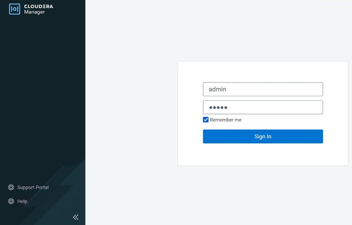
Note: The default username and password for Cloudera Manager is admin/admin.
Step 10. Upload license file for Cloudera Data Platform:
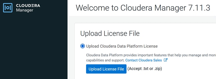
Step 11. Click Continue.
Procedure 2. Enable AutoTLS
Auto-TLS is managed using the certmanager utility, which is included in the Cloudera Manager Agent software, and not the Cloudera Manager Server software. You must install the Cloudera Manager Agent software on the Cloudera Manager Server host to be able to use the utility. You can use certmanager to manage auto-TLS on a new installation. For more information, go to: Configuring TLS Encryption for Cloudera Manager Using Auto-TLS
Step 1. Click the link to setup Enable AutoTLS through Cloudera Manager.
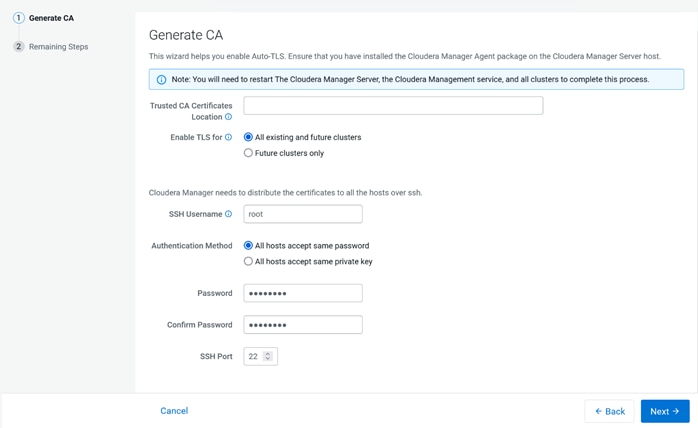
Step 2. Restart Cloudera Manager Server.
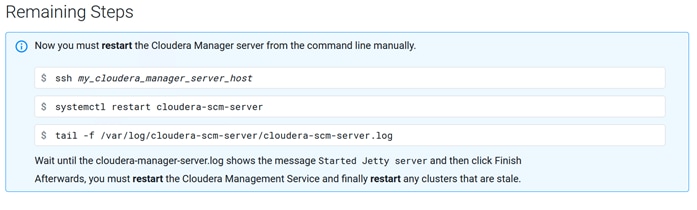
# systemctl restart cloudera-scm-server
# systemctl status cloudera-scm-server -l
Step 3. Login to Cloudera Manager using URL: https://<CM_Server_IP>:7183/
Step 4. Select type of cluster for deployment.
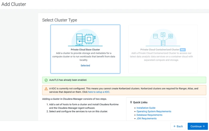
Cloudera Manager provides a wizard for integrating your organization’s Kerberos with your cluster to provide authentication services. Cloudera Manager clusters can be integrated with MIT Kerberos, Red Hat Identity Management (or the upstream FreeIPA), or Microsoft Active Directory. For more information, see Enable Kerberos Authentication for CDP.
Note: In our lab, we configured Active-Directory based Kerberos authentication. We presume that Active Directory is pre-configured with OU, user(s) and proper authentication is setup for Kerberos Authentication. LDAP users and bind users are expected to be in the same branch/OU.
Note: Before integrating Kerberos with your cluster, configure TLS encryption between Cloudera Manager Server and all Cloudera Manager Agent host systems in the cluster. During the Kerberos integration process, Cloudera Manager Server sends keytab files to the Cloudera Manager Agent hosts, and TLS encrypts the network communication, so these files are protected.
Note: For Active Directory, you must have administrative privileges to the Active Directory instance for initial setup and for on-going management, or you will need to have the help of your AD administrator prior to and during the integration process. For example, administrative access is needed to access the Active Directory KDC, create principals, and troubleshoot Kerberos TGT/TGS-ticket-renewal and take care of any other issues that may arise.
Step 1. In Cloudera Manager console, from Select Cluster Type, click Private Cloud Base Cluster, then select Click here to setup a KDC. Click Continue.

Step 2. Select Active Directory as shown below:
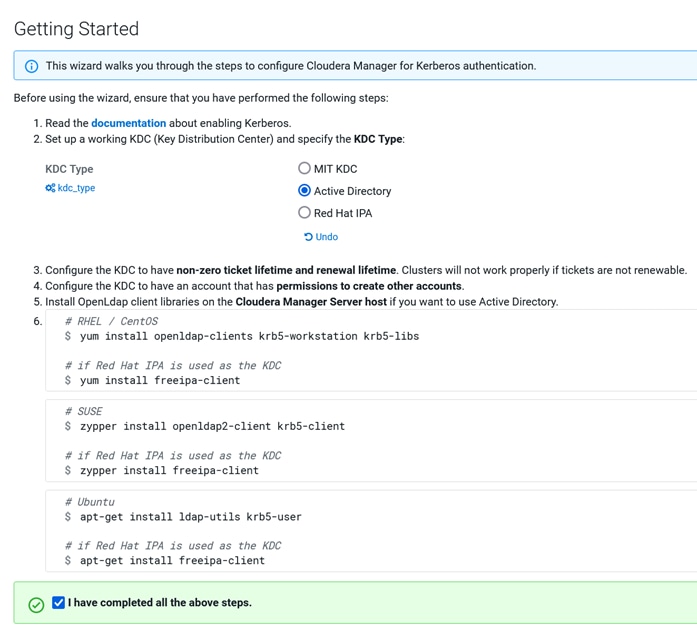
Step 3. As recommended, install the following in all Cloudera Manager hosts by running the following command. Once completed, click the checkbox “I have completed all the above steps” and click Continue.
# ansible all -m command -a "dnf install -y openldap-clients krb5-workstation krb5-libs"
Step 4. Enter KDC information for this Cloudera Manager. Use Table 5 as an example to fill-in the KDC setup information.
Table 5. KDC Setup components and their corresponding value
| Component |
Value |
| Kerberos Security Realm |
CDIP.CISCO.LOCAL |
| KDC Server Host |
winjb-ucsg16.cdip.cisco.local |
| KDC Admin Server Host |
winjb-ucsg16.cdip.cisco.local |
| Domain Name(s) |
cdip.cisco.local |
| Active Directory Suffix |
OU=cdip-kerberos,DC=cdip,DC=cisco,DC=local |
| Active Directory Delete Accounts on Credential Regeneration |
Select |
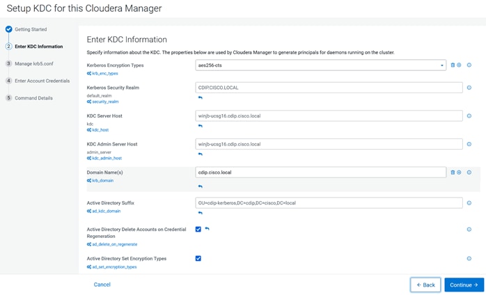
Note: In this setup, we used Kerberos authentication with Active Directory (AD). Setting up AD is beyond the scope of this document.
Step 5. Check the box for Manage “krb5.conf” through Cloudera Manager. This will install krb5.conf file in all the hosts selected for data lake.
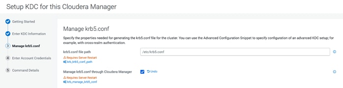
Step 6. Enter account credentials for the bind user which you have created in AD. This credential will be used to create service accounts in AD. In our lab setup, “cdpbind” user is created in AD for this purpose. Click Continue.
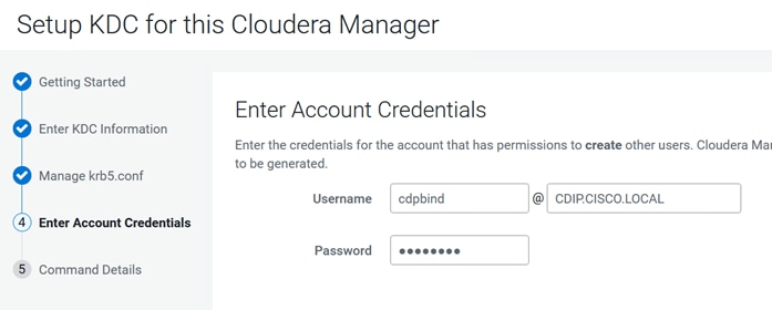
Step 7. Click Finish to complete the KDC setup.
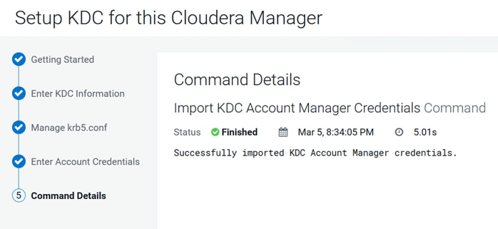
Once the KDC set up is completed, the Cloudera Manager wizard for adding a cluster displays the following:
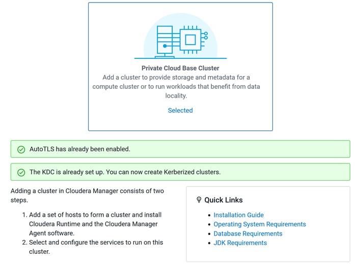
Step 8. Verify Kerberos configuration:
# kinit cdpbind@CDIP.CISCO.LOCAL
Password for cdpbind@CDIP.CISCO.LOCAL:
[root@cdip-nn1 ~]# klist
Ticket cache: KCM:0
Default principal: cdpbind@CDIP.CISCO.LOCAL
Valid starting Expires Service principal
03/05/2024 20:35:11 03/06/2024 20:35:07 krbtgt/CDIP.CISCO.LOCAL@CDIP.CISCO.LOCAL
renew until 03/12/2024 21:35:07
Procedure 4. Install Cloudera Private Cloud Base using the Cloudera Manager WebUI
Step 1. Enter a cluster name. Click Continue.
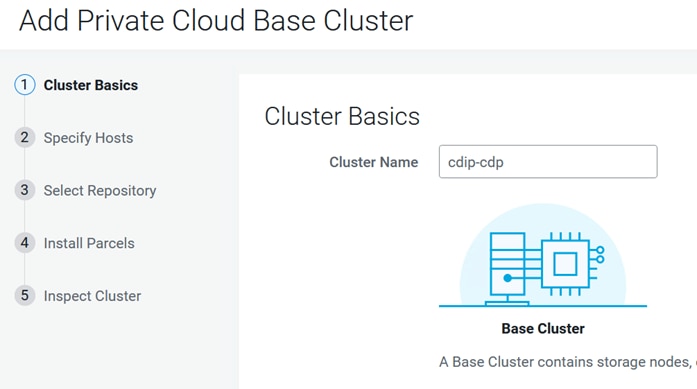
Step 2. Specify the hosts that are part of the cluster using their IP addresses or hostname. The figure below shows a pattern that specifies the IP addresses range. Cloudera Manager will "discover" the nodes based to add in the cluster. Verify that all desired nodes have been found and selected for installation.
cdip-dn[01-08].cdip.cisco.local
cdip-nn[01-03].cdip.cisco.local
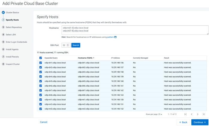
Step 3. Enter Custom Repository or Cloudera Repository to install Cloudera Manager Agent on all nodes in the cluster.
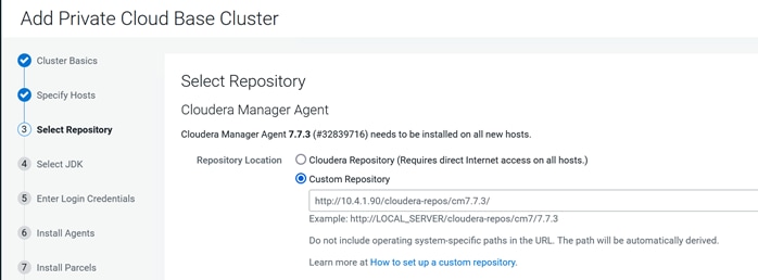
Step 4. In other software section, select Use Parcels and click Parcel Repository & Network Settings to provide custom Parcels location to be installed.
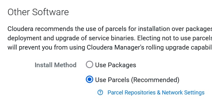
Step 5. Enter custom repository URL for CDH7 and CDS 3.3 parcels. Click Verify and Save. Close the Parcel Repository & Network Settings wizard.
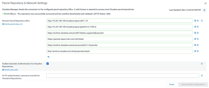
Step 6. Select the parcels for installation.
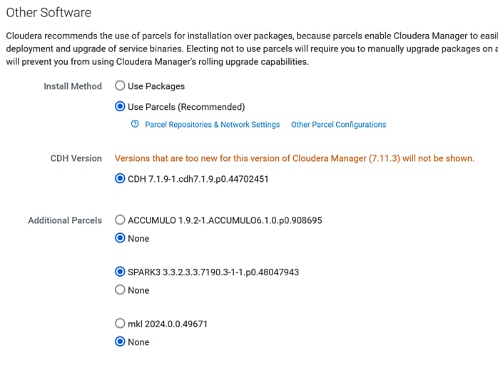
Step 7. Click Continue.
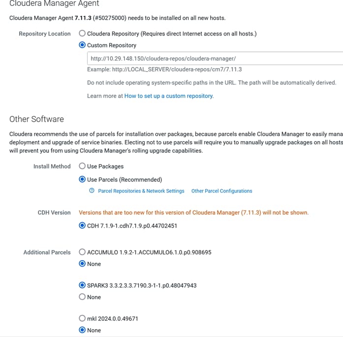
Step 8. Select the appropriate option for JDK, (manual installation for JDK11 with CDH 7.1.x and JDK17 with 7.1.9 and above).
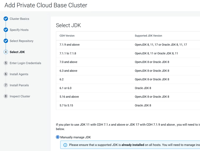
Step 9. Provide the SSH login credentials for the hosts to install Cloudera packages. Click Continue.
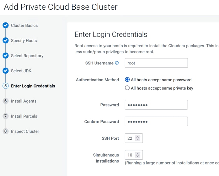
Step 10. Cloudera Agent installation wizard displays. Click Continue after the successful Cloudera Agent installation on all hosts.
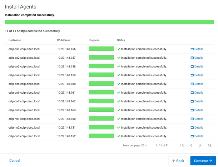
Step 11. Parcels Installation wizard reports status parcels distribution and activation on all hosts part of the cluster creation. Click Continue.
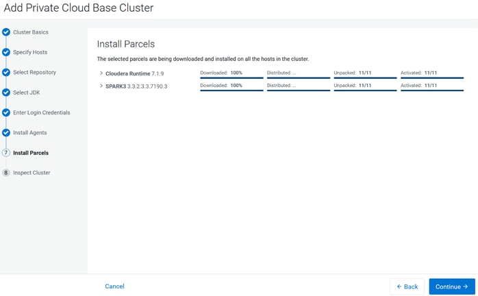
Step 12. Inspect Cluster by running Inspect Network Performance and Inspect Hosts for new cluster creation. Review inspector summary. Click Finish.
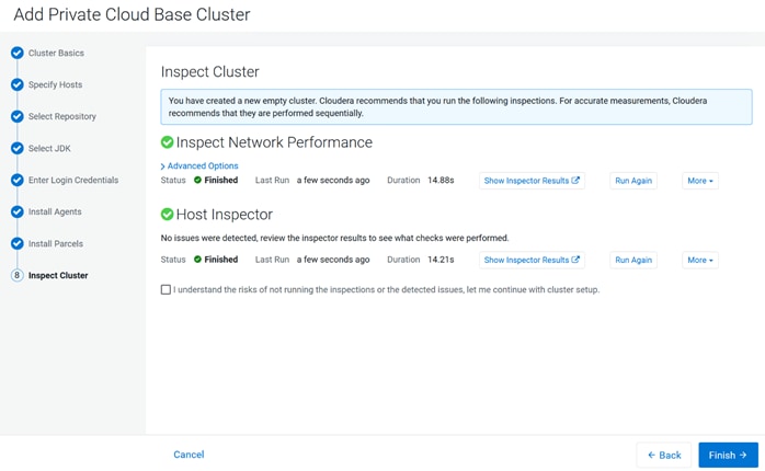
Step 13. Select services to install. Choose from a combination or services defined or select custom services. Services required based on selection will be automatically added.
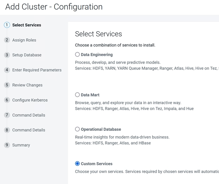
Note: It is important to select host(s) to deploy services based on role intended it for. For detailed information, go to: Runtime Cluster Hosts and Role Assignments
Table 6. Cloudera Data Platform Private Cloud Base host and Role assignment example
| Service Name |
Host |
| NameNode |
cdip-nn2, cdip-nn3 (HA) |
| HistoryServer |
cdip-nn2 |
| JournalNodes |
cdip-nn1, cdip-nn2, cdip-nn3 |
| ResourceManager |
cdip-nn2, cdip-nn3 (HA) |
| Hue Server |
cdip-nn1 |
| HiveMetastore Server |
cdip-nn1 |
| HiveServer2 |
cdip-nn2 |
| HBase Master |
cdip-nn2 |
| Oozie Server |
cdip-nn1 |
| ZooKeeper |
cdip-nn1, cdip-nn2, cdip-nn3 |
| DataNode |
cdip-dn1 – cdip-dn8 |
| NodeManager |
cdip01 to cdip16 |
| RegionServer |
cdip-dn1 – cdip-dn8 |
| Impala Catalog Server Daemon |
cdip-nn2 |
| Impala State Store |
cdip-nn3 |
| Impala Daemon |
cdip-dn1 – cdip-dn8 |
| Solr Server |
cdip-dn3 (can be installed on all hosts if needed if there is a search use case) |
| Spark History Server |
cdip-nn2 |
| Spark Executors |
cdip-dn1 – cdip-dn8 |
Step 14. Select services and host assignment in Add cluster configuration wizard.
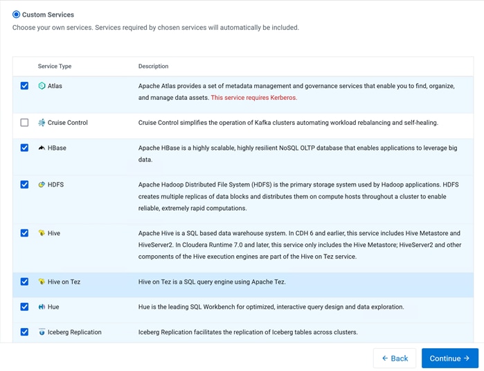
Step 15. Assign roles. Click Continue.
Step 16. Select database type and enter database hostname, username, and password on Setup database. Click Test Connection. After a successful connection test, click Continue.
● Reports Manager
● Oozie Server
● Ranger
● Hive
● YARN Queue Manager
● Hue
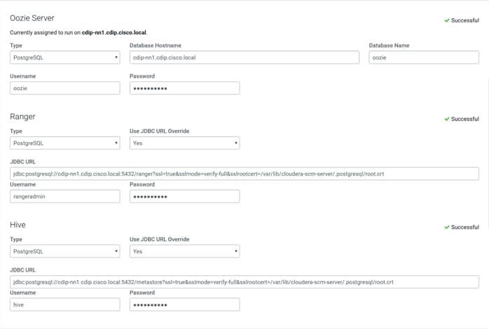
Step 17. Enter the required parameters.
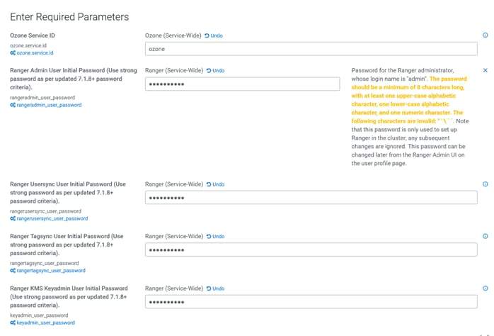
Step 18. Review the changes and edit the configuration parameters as per your requirements.
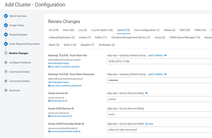
Step 19. Configure Kerberos and Keep Review and customize the configuration changes based on your requirements.
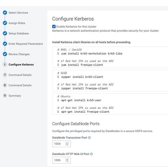
Step 20. Click Continue after Cloudera Manager successfully runs enable Kerberos command.
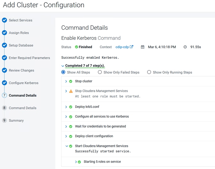
Step 21. Installation wizard run first command to start cluster roles and services. Click Continue.
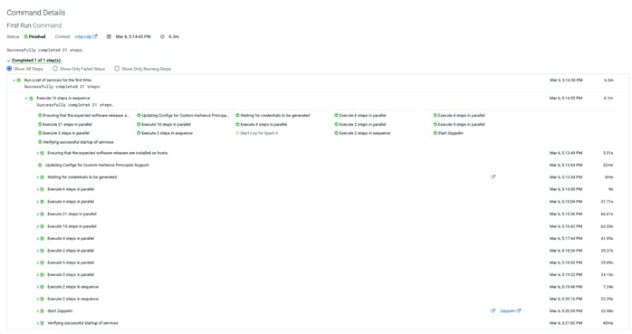
Step 22. Click Finish on the Summary page.
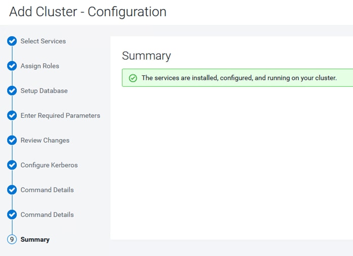
Note: You might need to adjust configuration parameters of the cluster after successful first run command execution. Apply the changes and restart the cluster.
For Impala, Hive, Hive on Tez edit value for
Ranger Plugin URL Auth Filesystem Schemes - file:,wasb:,adl:
Enable Kerberos Authentication for HTTP Web-Consoles - HBase (Service-Wide). Click on Generate missing credentials for Kerberos
For TLS/SSL enabled HDFS configuration you might see a warning as “DataNode configuration is valid, but not recommended. There are two recommended configurations: (1) DataNode Transceiver Port and Secure DataNode Web UI Port (TLS/SSL) both >= 1024, DataNode Data Transfer Protection set, Hadoop TLS/SSL enabled; (2) DataNode Transceiver Port and DataNode HTTP Web UI Port both < 1024, DataNode Data Transfer Protection not set, Hadoop TLS/SSL disabled.”
DataNode Transceiver Port (dfs_datanode_port)- 9866
DataNode HTTP Web UI Port (dfs.datanode.http.address) - 9864
DataNode Data Transfer Protection (dfs.data.transfer.protection) – Authentication
Procedure 5. Configure Ranger with SSL/TLS enabled PostgreSQL Database
Step 1. Login to Cloudera Manager Web Console. Go to Ranger > Configuration.
● Ranger DB SSL Enabled – Checked
● Ranger DB SSL Required – Checked
● Ranger DB SSL Verify Server Certificate – Checked
● Ranger DB Auth Type – 1-way
● Ranger Admin Database SSL Certificate File - /var/lib/ranger/ or custom path
● Ranger Database JDBC Url Override - jdbc:postgresql://<db_host>:<db_port>/<db_name>?sslmode=verify-full&sslrootcert=<server_certificate_path>
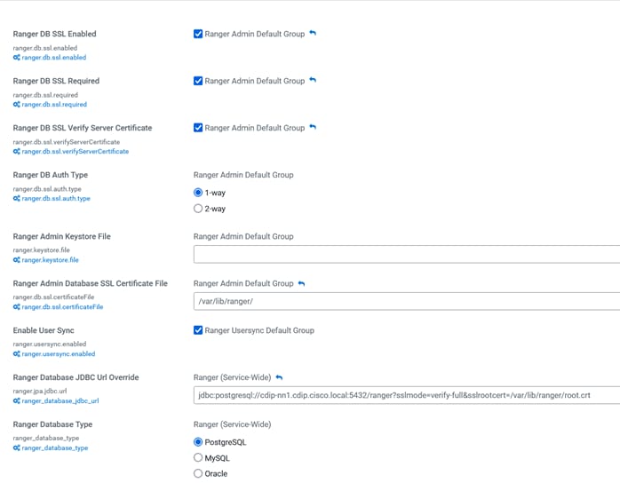
For more information, go to: https://docs.cloudera.com/cdp-private-cloud-base/7.1.9/installation/topics/cdpdc-enable-ssl-tls-ranger-postgres-db.html?
Note: Restart required for rangeradmin after updating Ranger configuration.
Note: In addition, set Load Balancer Address – http://<ranger_host>:6080
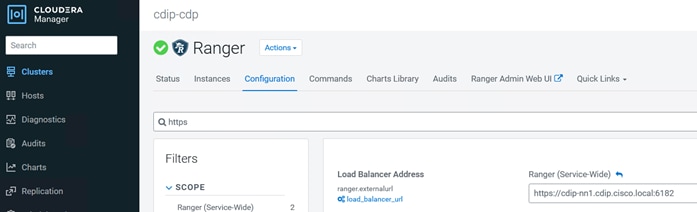
Procedure 6. Configure Hive metastore with SSL/TLS enabled PostgreSQL Database
Step 1. In Cloudera Manager Web console; go to Hive > Configuration > Hive Metastore Database JDBC URL Override.
Step 2. Edit the value as jdbc:postgresql://<db_host>:<db_port>/<db_name>?sslmode=verify-full&sslrootcert=<server_certificate_path>
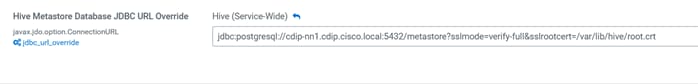
Note: Restart required for Hive Metastore Server and HiveServer2 after updating Ranger configuration.
Scale the Cluster
The role assignment recommendation for different size of cluster can be found here: https://docs.cloudera.com/cdp-private-cloud-base/7.1.9/installation/topics/cdpdc-runtime-cluster-hosts-role-assignments.html
Note: When High Availability (HA) is enabled and the total number of nodes is under 10, you must carefully plan the composition of the worker nodes. That is the utility nodes and master nodes. If you decide that your development cluster is to be HA enabled, you must add the HA configuration for at least 3-10 hosts for seamless performance.
Enable High Availability
Note: Setting up High Availability is done after the Cloudera Installation is completed, see: https://docs.cloudera.com/cdp-private-cloud-base/7.1.9/managing-clusters/topics/cm-high-availability.html
Configure Browsers for Kerberos Authentication
Note: To enable specific web browsers to use SPNEGO to negotiate Kerberos authentication, go to: https://docs.cloudera.com/cdp-private-cloud-base/7.1.9/security-how-to-guides/topics/cm-security-browser-access-kerberos-protected-url.html
Cloudera Data Platform Cloud Data Services Installation
CDP Private Cloud Data Services works on top of CDP Private Cloud Base and is the on-premises offering of Cloudera Data Platform (CDP) that brings many of the benefits of the public cloud deployments to on-premises CDP deployments. CDP Private Cloud Data Services lets you deploy and use the Cloudera Data Warehouse (CDW), Cloudera Machine Learning (CML), and Cloudera Data Engineering (CDE) Data Services.
This section summarizes Cloudera Private Cloud Data Science v1.5.3 installation through Embedded Container Service on Cloudera Private Cloud Base 7.1.9.
A CDP Private Cloud Data Services deployment includes an Environment, a Data Lake, the Management Console, and Data Services (Data Warehouse, Machine Learning, Data Engineering). Other tools and utilities include Replication Manager, Data Recovery Service, CDP CLI, and monitoring using Grafana.
To deploy CDP Private Cloud Data Services you need a CDP Private Cloud Base cluster, along with container-based clusters that run the Data Services. You can either use a dedicated RedHat OpenShift container cluster or deploy an EmbeddedContainer Service (ECS) container cluster.
The Private Cloud deployment process involves configuring Management Console, registering an environment by providing details of the Data Lake configured on the Base cluster, and then creating the workloads.
Platform Managers and Administrators can rapidly provision and deploy the data services through the Management Console, and easily scale them up or down as required.
CDP Private Cloud Base provides the following components and services that are used by CDP Private Cloud Data Services:
● SDX Data Lake cluster for security, metadata, and governance
● HDFS and Ozone for storage
● Powerful and open-source Cloudera Runtime services such as Ranger, Atlas, Hive Metastore (HMS), and so on
● Networking infrastructure that supports network traffic between storage and compute environments
CDP Private Cloud Base Checklist
Cloudera support matrix lists the supported software for the CDP Private Cloud Base cluster and the CDP Private Cloud Data Services containerized cluster.
Review the CDP Private Cloud Base Checklist here: https://docs.cloudera.com/cdp-private-cloud-data-services/1.5.3/installation-ecs/topics/cdppvc-installation-pvcbase-checklist.html
Procedure 1. Configure Cloudera Manager for external authentication using LDAP
An LDAP-compliant identity/directory service, such as OpenLDAP, provides different options for enabling Cloudera Manager to look-up user accounts and groups in the directory:
● Use a single Distinguished Name (DN) as a base for matching usernames in the directory.
or
● Search filter options let you search for a particular user based on somewhat broader search criteria – for example Cloudera Manager users could be members of different groups or organizational units (OUs), so a single pattern does not find all those users. Search filter options also let you find all the groups to which a user belongs, to help determine if that user should have login or admin access.
Note: The LDAP Distinguished Name Pattern property is deprecated. Leave this field empty while configuring authentication using LDAP in Cloudera Manager.
Step 1. Obtain CA certificate from active directory and copy it as for example:
# cp ad.cert.cer /etc/pki/ca-trust/source/anchors/ad.cert.pem
# update-ca-trust force-enable
# update-ca-trust extract
# update-ca-trust check
Step 2. Update AutoTLS configuration by rotating Auto-TLS certificate with new CA certificate obtained.
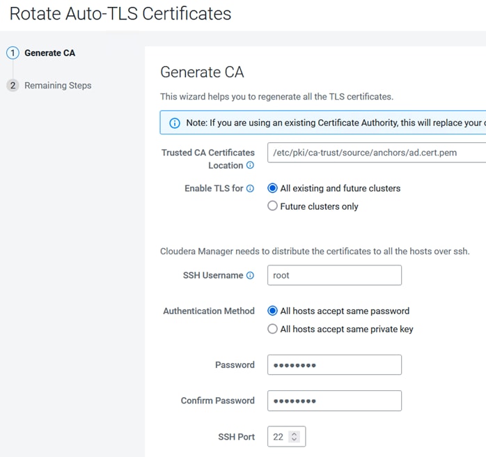
Step 3. Restart Cloudera server configuration and restart cluster role/services and deploy client configuration:
# systemctl restart cloudera-scm-server
# systemctl status cloudera-scm-server.service -l
# tail -f /var/log/cloudera-scm-server/cloudera-scm-server.log
Step 4. Login to Cloudera Manager admin console.
Step 5. Select Administration > Settings.
Step 6. Select external authentication for the category shown in the screenshot below:
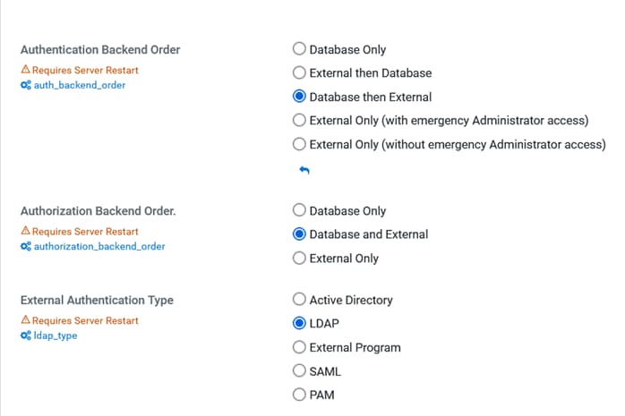
Step 7. Search for “ldap” and enter values for ldap authentication.
Step 8. Record DistinguishedName for domain, organization unit and user:
◦ LDAP Group Search Base - DC=cdip,DC=cisco,DC=local
◦ LDAP User Search Base - OU=cloudera,DC=cdip,DC=cisco,DC=local
◦ LDAP Bind User Distinguished Name - CN=cdpbind,OU=cloudera,DC=cdip,DC=cisco,DC=local
◦ LDAP User Search Filter - sAMAccountName={0}
◦ LDAP Group Search Filter - member={0}
◦ Active Directory Domain - cdip.cisco.local
◦ LDAP URL - ldap://winjb-ucsg16.cdip.cisco.local/dc=cdip,dc=cisco,dc=local
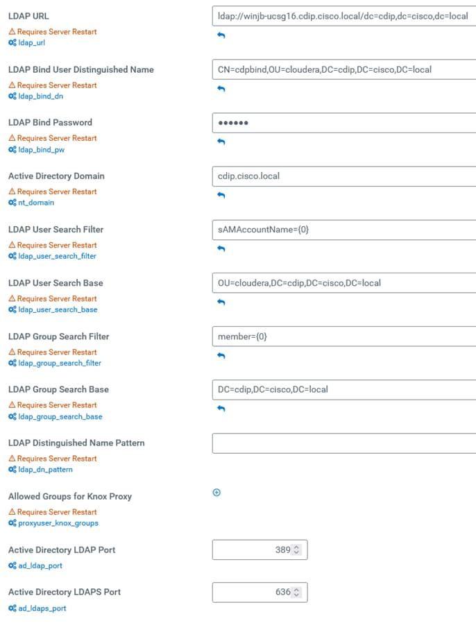
Step 9. In Administration > Users & Roles > LDAP/PAM Groups, add LDAP/PAM Group mapping.
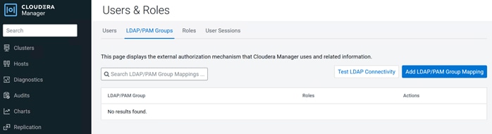
Step 10. Add LDAP/PAM Group mapping value and Roles to assign.
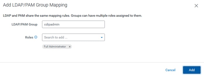
Step 11. Click Test LDAP Connectivity.
Step 12. Provide a username and password for an LDAP user to test whether that user can be authenticated.
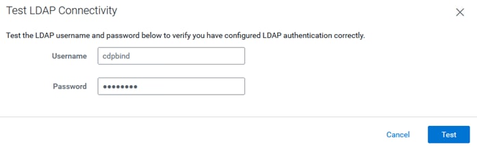
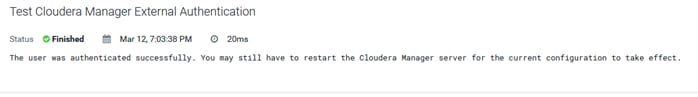
Step 13. Restart the Cloudera Manager Server.
Step 14. Login to Cloudera Manager WebUI and assign Roles for new user
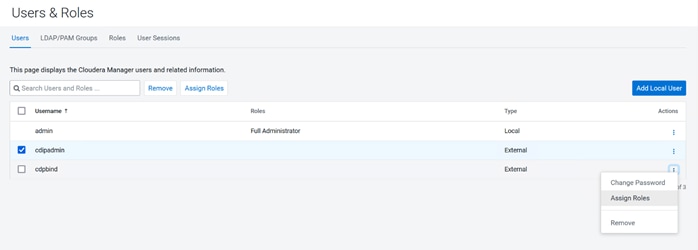
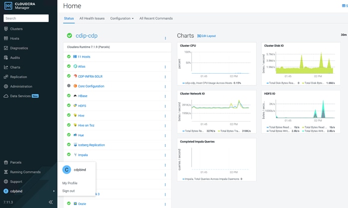
Procedure 2. Configure Ranger authentication for LDAP
Step 1. In Cloudera Manager, select Ranger, then click the Configuration tab.
Step 2. To display the authentication settings, type "authentication" in the Search box. Scroll down to see all of the LDAP settings.
Step 3. Select LDAP for "Admin Authentication Method."
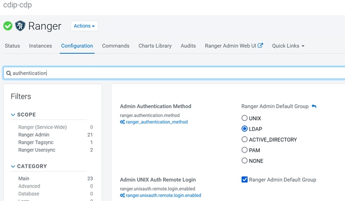
Step 4. Configure the following settings for LDAP authentication. Example values set are shown below:
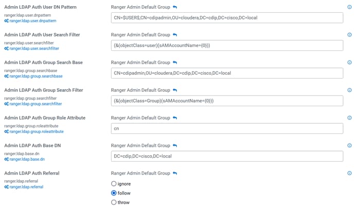
Step 5. Edit ranger.ldap.ad.referral - follow
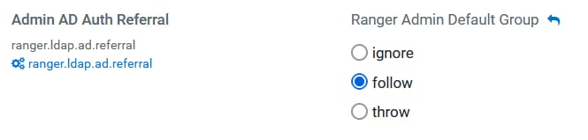
Step 6. Edit Usersync configuration. Example values set are shown below:
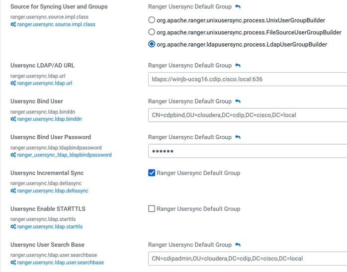
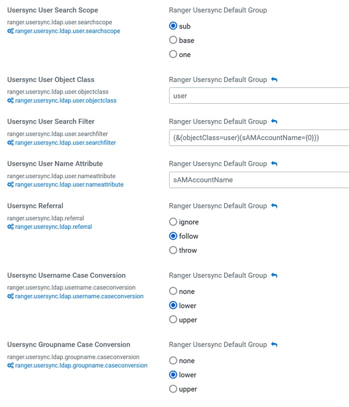
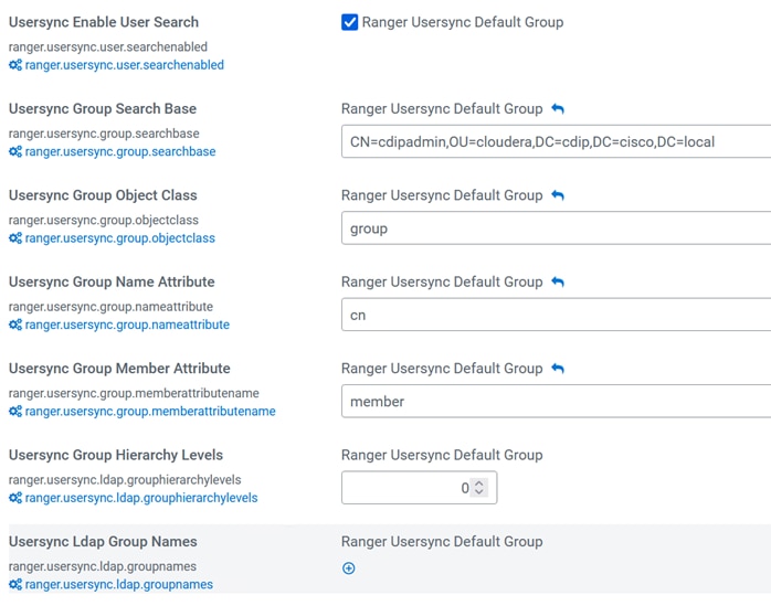
Step 7. Click Save Changes.
Step 8. Restart Ranger service.
Step 9. Login to Ranger Admin Webui With Ldap Authentication.
For more information, go to: https://docs.cloudera.com/cdp-private-cloud-base/7.1.9/security-ranger-authentication-unix-ldap-ad/topics/security-ranger-authentication-ldap-settings.html
Procedure 3. Configure Hue for LDAP Authentication
Configuring Hue for Lightweight Directory Access Protocol (LDAP) enables you to import users and groups from a directory service, synchronize group membership manually or automatically at login, and authenticate with an LDAP server. Hue supports Microsoft Active Directory (AD) and open standard LDAP such as OpenLDAP and Forgerock OpenDJ Directory Services.
Step 1. Login to Cloudera Manager. Go to Cluster > Hue > Configuration.
Step 2. Change value for Authentication Backend – desktop.auth.backend.LdapBeckend,desktop.auth.backend.AllowFirstUserDjangoBackend

Step 3. Edit value for LDAP configuration. Example values set are shown below:
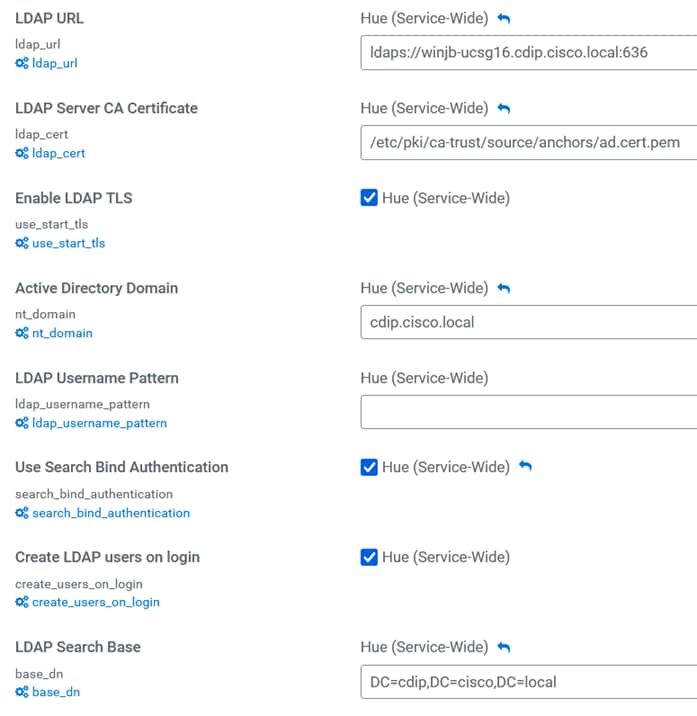
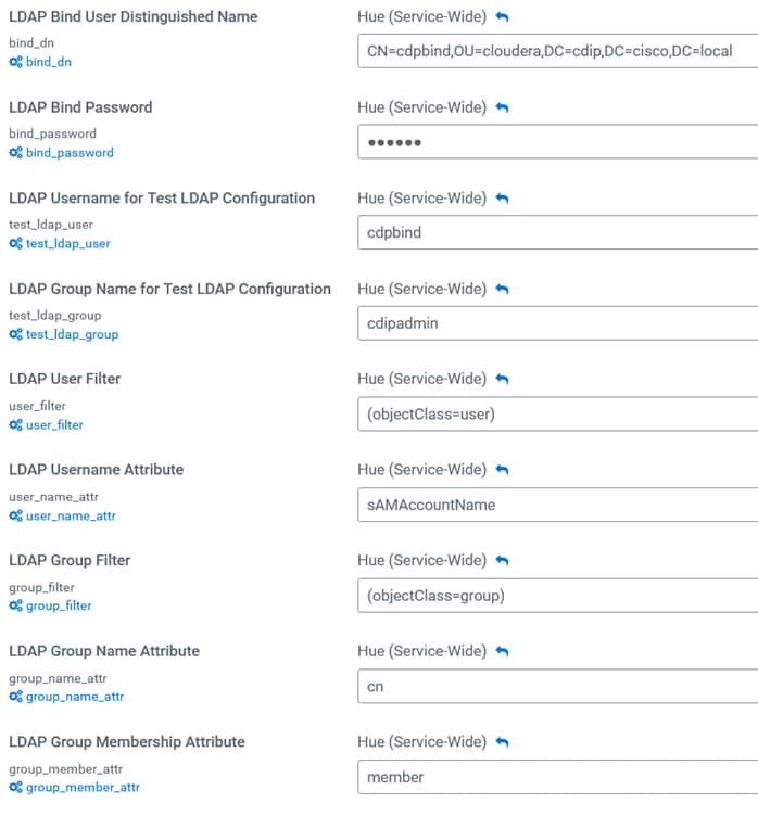
Step 4. Click Save Changes.
Step 5. Restart Hue service.
Step 6. Click Actions next to Hue. Click Test Ldap Configuration.
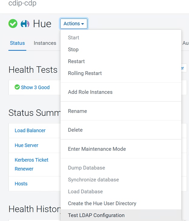
Step 7. Click Test LDAP Configuration.
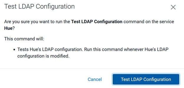
Step 8. Click Finish.
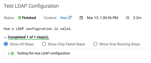
For more information, go to: https://docs.cloudera.com/cdp-private-cloud-base/7.1.9/securing-hue/topics/hue-authenticate-users-with-ldap.html
Procedure 4. Configure Atlas for LDAP Authentication
Step 1. Login to Cloudera Manager WebUI. Go to Cluster > Atlas > Configuration.
Step 2. Edit LDAP configuration. A sample configuration is shown below:
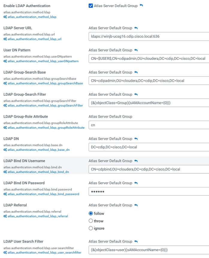
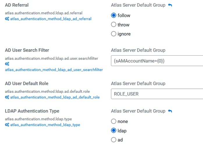
Step 3. Click Save Changes.
Step 4. Restart Atlas Service.
For more information, go to: https://docs.cloudera.com/cdp-private-cloud-base/7.1.9/atlas-securing/topics/atlas-configure-ldap-authentication.html
Procedure 5. Configure Hive for LDAP Authentication
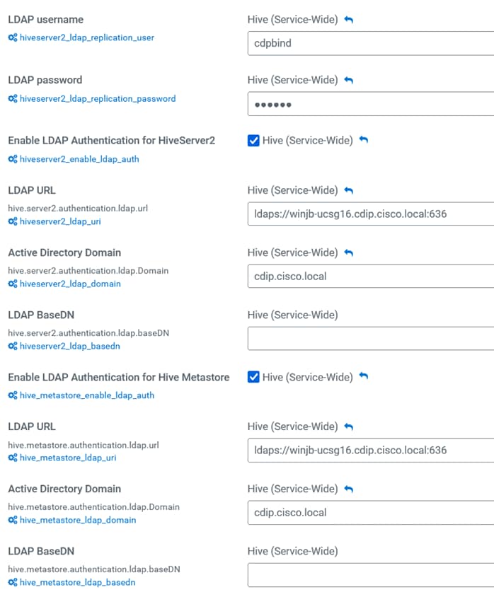
Procedure 6. Configure HDFS properties to optimize log collection
CDP uses “out_webhdfs” Fluentd output plugin to write records into HDFS, in the form of log files, which are then used by different Data Services to generate diagnostic bundles. Over time, these log files can grow in size. To optimize the size of logs that are captured and stored on HDFS, you must update certain HDFS configurations in the hdfs-site.xml file using Cloudera Manager.
Step 1. Login to Cloudera Manager WebUI.
Step 2. Go to Cluster > HDFS Service > Configuration.
Step 3. Enable WebHDFS.
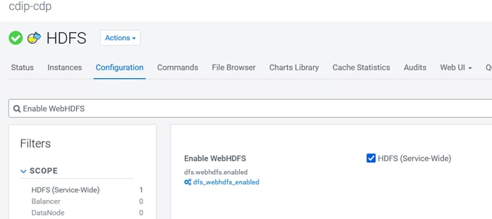
Step 4. Edit value for HDFS Service Advanced Configuration Snippet (Safety Valve) for hdfs-site.xml as shown in below:
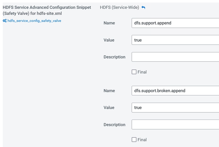
Step 5. Click Save Changes.
Step 6. Restart the HDFS service.
Step 7. Restart CDP Private Cloud Base cluster.
Embedded Container Service (ECS) Checklist
Use the checklist for Embedded Container Service (ECS) for CDP Private Cloud Data Services: https://docs.cloudera.com/cdp-private-cloud-data-services/1.5.3/installation-ecs/topics/cdppvc-installation-ds-checklist.html
Procedure 7. CDP Private Cloud Data Services Software Requirements
● You must have a minimum of one agent node for ECS.
● Enable TLS on the Cloudera Manager cluster for communication with components and services.
● Set up Kerberos on these clusters using an Active Directory.
● The default docker service uses /docker folder. Whether you wish to retain /docker or override /docker with any other folder, you must have a minimum of 300 GiB free space.
● Ensure that all of the hosts in the ECS cluster have more than 300 GiB of free space in the /var/lib directory at the time of installation.
● The cluster generates multiple hosts and host-based routing is used in the cluster in order to route it to the right service. You must decide on a domain for the services which Cloudera Manager by default points to one of the host names on the cluster. However, during the installation, you should check the default domain and override the default domain (only if necessary) with what you plan to use as the domain. The default domain must have a wildcard DNS entry. For example, “*.apps.myhostname.com.”
● It is recommended that you leave IPv6 enabled at the OS level on all ECS nodes.
● Python 3.8 is required for Cloudera Manager version 7.11.3.0 and higher versions. Cloudera Manager agents will not start unless Python 3.8 is installed on the cluster nodes.
Step 1. Enable cgroup v1 in Red Hat Enterprise Linux 9:
# In RHEL 9 cgroup-v2 is enabled by default, follow steps below to enable cgroup v1:
# Check if the cgroup-v2 is mounted currently as default.
mount | grep cgroup
# Add the kernel command line parameter systemd.unified_cgroup_hierarchy=0 & systemd.legacy_systemd_cgroup_controller.
grubby --update-kernel=/boot/vmlinuz-$(uname -r) --args="systemd.unified_cgroup_hierarchy=0 systemd.legacy_systemd_cgroup_controller"
# Reboot the system for changes to take effect.
systemctl reboot
# Verify the changes after reboot:
cat /proc/cmdline
BOOT_IMAGE=(hd0,gpt2)/vmlinuz-5.14.0-162.23.1.el9_1.x86_64 root=/dev/mapper/rhel-root ro crashkernel=1G-4G:192M,4G-64G:256M,64G-:512M resume=/dev/mapper/rhel-swap rd.lvm.lv=rhel/root rd.lvm.lv=rhel/swap rhgb quiet systemd.unified_cgroup_hierarchy=0 systemd.legacy_systemd_cgroup_controller
# Mount shows legacy cgroup-v1 mounted now.
mount | grep cgroup
ll /sys/fs/cgroup
Step 2. For CML, you must install nfs-utils in order to mount longhorn-nfs provisioned mounts. The nfs-utils package is required on every node of the ECS cluster. Run this command yum install nfs-utils to install nfs-utils:
# ansible ecsnodes -m shell -a "dnf install -y nfs-utils"
Step 3. For nodes with NVIDIA GPU, ensure that the GPU hosts have NVIDIA drivers and nvidia-container-runtime installed. You must confirm that drivers are properly loaded on the host by executing the command nvidia-smi. You must also install the nvidia-container-toolkit package.
Step 4. You must install nvidia-container-toolkit. (nvidia-container-runtime migrated to nvidia-container-toolkit , see Migration Notice.) The steps for this are in the NVIDIA Installation Guide. If using Red Hat Enterprise Linux (RHEL), use dnf to install the package. See installing the NVIDIA Container Toolkit.
Verify linux version:
# ansible ecsnodes -m shell -a "uname -m && cat /etc/*release"
# ansible ecsnodes -m shell -a "uname -a"
Verify GCC installation and version
# ansible ecsnodes -m shell -a "gcc --version"
Verify nodes with NVIDIA GPU installed:
# ansible ecsnodes -m shell -a "lspci -nnv | grep -i nvidia"
Set subscription to RHEL9.1
# ansible all -m shell -a "subscription-manager release --set=9.1" # Set subscription manager to RHEL 9.1
# ansible all -m shell -a "subscription-manager release --show"
# ansible all -m shell -a "sudo dnf clean all"
# ansible all -m shell -a "sudo rm -rf /var/cache/dnf"
(Optional if not completed prior) Enable optional repos - On RHEL 9 Linux only
# ansible ecsnodes -m shell -a "subscription-manager repos --enable=rhel-9-for-x86_64-appstream-rpms"
# ansible ecsnodes -m shell -a "subscription-manager repos --enable=rhel-9-for-x86_64-baseos-rpms"
# ansible ecsnodes -m shell -a "subscription-manager repos --enable=codeready-builder-for-rhel-9-x86_64-rpms"
Install kernel headers and development packages for the currently running kernel
# ansible ecsnodes -m shell -a "sudo dnf install kernel-devel-$(uname -r) kernel-headers-$(uname -r)"
Remove outdated Signing Key:
# ansible ecsnodes -m shell -a "sudo rpm --erase gpg-pubkey-7fa2af80*"
Download and Install NVIDIA CUDA Toolkit [This exercise documented with CUDA 12.3.2 for RHEL 9 rpm(local) installation]
# wget https://developer.download.nvidia.com/compute/cuda/12.2.2/local_installers/cuda-repo-rhel9-12-2-local-12.2.2_535.104.05-1.x86_64.rpm
# scp cuda-repo-rhel9-12-2-local-12.2.2_535.104.05-1.x86_64.rpm root@cdip-nn1:/root/.
# ansible ecsnodes -m copy -a "src=/root/cuda-repo-rhel9-12-2-local-12.2.2_535.104.05-1.x86_64.rpm dest=/root/cuda-repo-rhel9-12-2-local-12.2.2_535.104.05-1.x86_64.rpm"
# ansible ecsnodes -m shell -a "sudo rpm --install cuda-repo-rhel9-12-2-local-12.2.2_535.104.05-1.x86_64.rpm"
# From NVIDIA Driver Downloads page, download NVIDIA Driver https://www.nvidia.com/download/index.aspx as per the GPU, OS and NVIDIA CUDA version.
# wget https://nvidia.github.io/libnvidia-container/stable/rpm/nvidia-container-toolkit.repo
# scp nvidia-driver-local-repo-rhel9-535.161.07-1.0-1.x86_64.rpm root@cdip-nn1:/root/.
# ansible ecsnodes -m copy -a "src=/root/nvidia-driver-local-repo-rhel9-535.161.07-1.0-1.x86_64.rpm dest=/root/nvidia-driver-local-repo-rhel9-535.161.07-1.0-1.x86_64.rpm"
# ansible ecsnodes -m shell -a "sudo rpm --install nvidia-driver-local-repo-rhel9-535.161.07-1.0-1.x86_64.rpm”
# ansible ecsnodes -m shell -a "sudo dnf clean all"
# ansible ecsnodes -m shell -a "sudo dnf -y module install nvidia-driver:latest-dkms"
# ansible ecsnodes -m shell -a "sudo dnf -y install cuda"
Enable nvidia-persistenced services:
# ansible ecsnodes -m shell -a "sudo systemctl enable nvidia-persistenced.service"
Reboot the machine:
# sudo systemctl reboot
After the machine boots, verify that the NVIDIA drivers are installed properly:
# nvidia-smi
Installing with dnf
Configure the production repository:
# cd
# scp nvidia-container-toolkit.repo root@cdip-nn1:/root/nvidia-container-toolkit.repo
# ansible ecsnodes -m copy -a "src=/root/nvidia-container-toolkit.repo dest=/etc/yum.repos.d/nvidia-container-toolkit.repo"
#
# ansible ecsnodes -m shell -a "sudo dnf config-manager --enable nvidia-container-toolkit-experimental"
# ansible ecsnodes -m shell -a "sudo dnf install -y nvidia-container-toolkit"
Note: Prepare CDP Private Cloud Base for the Private Cloud Data Services installation: https://docs.cloudera.com/cdp-private-cloud-data-services/1.5.3/installation-ecs/topics/cdppvc-installation-ecs-prepare-cdp-private-cloud-base.html
Note: Use this checklist to ensure that your CDP Private Cloud Base is configured and ready for installing CDP Private Cloud Data Services: https://docs.cloudera.com/cdp-private-cloud-data-services/1.5.3/installation-ecs/topics/cdppvc-installation-pvcbase-checklist.html
Note: For more information about CDP Private Cloud Data Services Software Requirement, go to: https://docs.cloudera.com/cdp-private-cloud-data-services/1.5.3/installation-ecs/topics/cdppvc-installation-ecs-software-requirements.html
Note: For more information about specific software requirements, see the Software Support Matrix for ECS.
Note: Use this checklist to ensure that your Embedded Container Service (ECS) is configured and ready for installing CDP Private Cloud Data Services: https://docs.cloudera.com/cdp-private-cloud-data-services/1.5.3/installation-ecs/topics/cdppvc-installation-ds-checklist.html
Install Cloudera Data Platform Private Cloud Data Services using ECS
Follow the steps detailed in this section to add hosts to be part of the Cloudera Private Cloud Data Services cluster and the install ECS (embedded container service) through either internet or airgapped method.
Note: We installed CDP Private Cloud Data Services using the airgapped method.
Note: If you do not have entitlements to access https://archive.cloudera.com/p/cdp-pvc-ds/latest/, contact your Cloudera account team to get the necessary entitlements.
Procedure 1. Install CDP Private Cloud Data Services using ECS
Step 1. In Cloudera Manager WebUI console, Go to Hosts. Click Add Hosts.
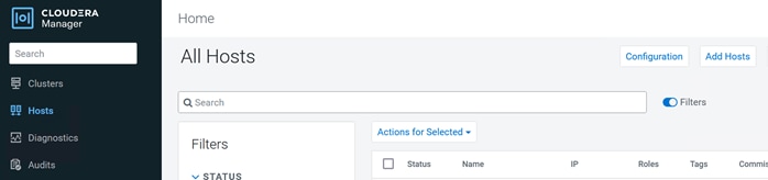
Step 2. Select Add hosts to Cloudera Manager. Complete requirement for Kerberos enablement on new hosts.
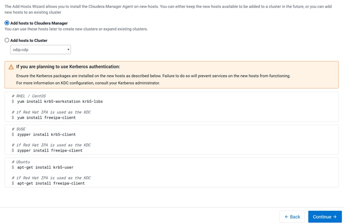
Step 3. Click Continue for Setup Auto-TLS.
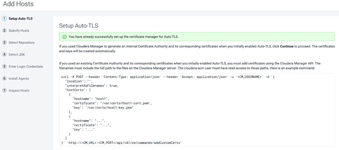
Step 4. Specify Hosts to be added in Cloudera Manager.
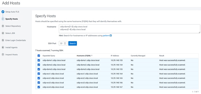
Step 5. Select Repository and add Custom Repository for air gapped installation.
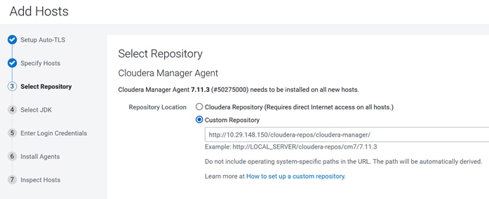
Step 6. Select JDK (manual installation for JDK11 with CDH 7.1.x and JDK17 with 7.1.9 and above).
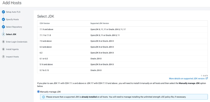
Step 7. Enter Login Credentials.
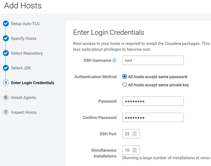
Step 8. Click Continue after a successful agent installation on hosts to be added in Cloudera Manager.
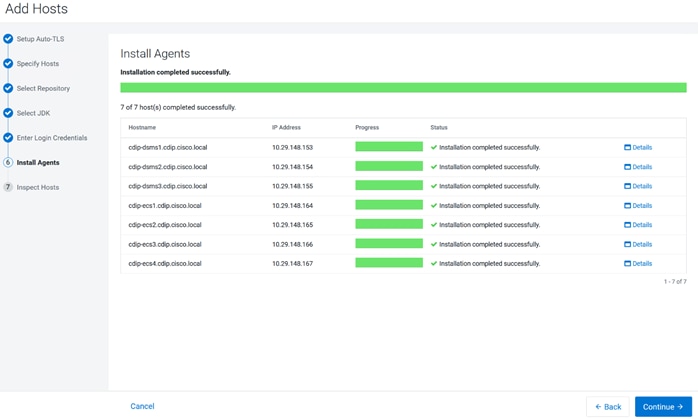
Step 9. Review Inspect Hosts validation result. Click Finish.
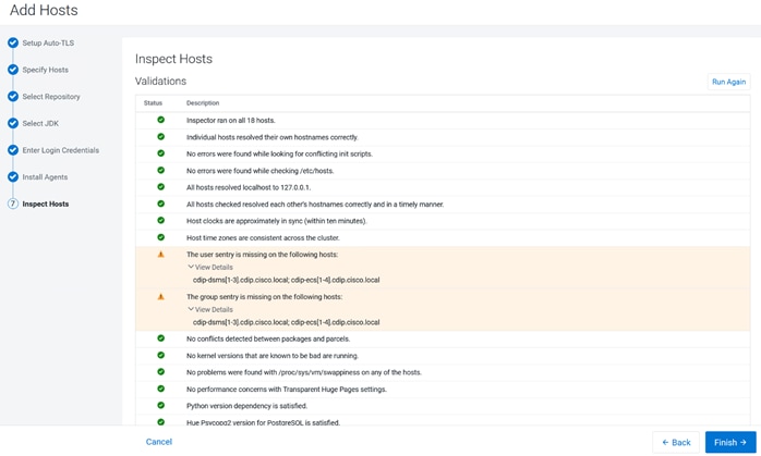
Step 10. To reserve a GPU node in Cloudera Private Cloud Data Services ECS cluster, assign a taint to the node. Set the node taint “nvidia.com/gpu: true:NoSchedule” For more information about setting up GPU node, go to: https://docs.cloudera.com/machine-learning/1.5.3/private-cloud-requirements/topics/ml-gpu-node-setup.html
Step 11. To setup GPU node for ECS, go to Hosts > Configuration.
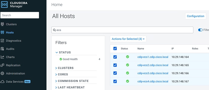
Step 12. Click Add Host Overrides to edit the value for Data Services: Restrict workload types (node_taint).
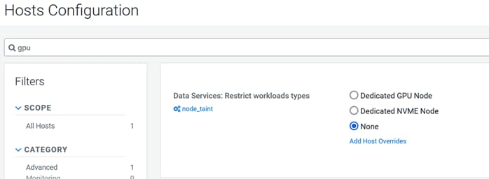
Step 13. Add Host Overrides for the ECS nodes as per the requirement. For example, we selected two of the four nodes as Dedicated GPU Node.
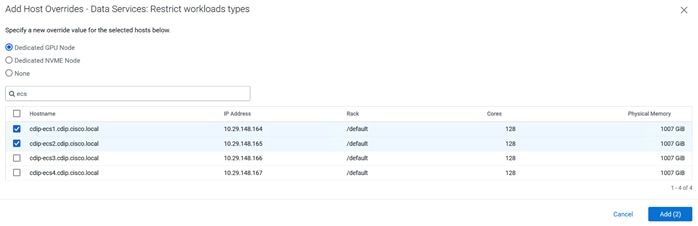
Step 14. Click Add and click Save Changes.
Note: For more information about dedicating the ECS node for specific workload type, go to: https://docs.cloudera.com/cdp-private-cloud-data-services/1.5.3/managing-ecs/topics/cm-managing-ecs-dedicating-nodes-for-workloads.html
Step 15. In Cloudera Manager WebUI console, go to Data Services page.
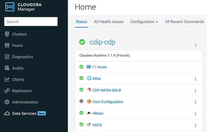
Step 16. Click Continue on page for Add Private Cloud Containerized Cluster.
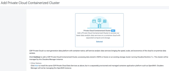
Step 17. From the Getting Started page select either Internet or Air Gapped installation.
Step 18. For Air Gapped installation run the following:
# mkdir cdp-pvc-ds
# cd cdp-pvc-ds
# wget -l 0 –recursive –no-parent -e robots=off -nH –cut-dirs=2 –reject=”index.html*” -t 10 https://<username>:<password>@archive.cloudera.com/p/cdp-pvc-ds/latest
# Modify the file manifest.json inside the downloaded directory, change “http_url”: “…” to
“http_url”: http://your_local_repo/cdp-pvc-ds/latest
mkdir -p /var/www/html/cloudera-repos/cdp-pvc-ds/
cd /var/www/html/cloudera-repos/cdp-pvc-ds/
scp -r 1.5.3/ root@cdip-nn1:/var/www/html/cloudera-repos/cdp-pvc-ds/
# cd /var/www/html/cloudera-repos/cdp-pvc-ds/1.5.3/
# ls -lt
total 116300
-rw-r–r–1 root root 284820 Mar 15 10:13 manifest.json
-rw-r–r–1 root root 118747085 Mar 15 10:13 cdp-private-1.5.3-b297.tgz
drwxr-xr-x 2 root root 4096 Mar 15 10:13 parcels
drwxr-xr-x 2 root root 4096 Mar 15 10:12 manifests
drwxr-xr-x 2 root root 32768 Mar 15 10:12 images
# vi manifest.json
“http_url”: “http://10.29.148.150/cloudera-repos/cdp-pvc-ds/1.5.3”
##### Mirror the downloaded directory to your local http server, e.g. http://your_local_repo/cdp-pvc-ds/latest
##### Add http://your_local_repo/cdp-pvc-ds/latest to your Custom Repository settings and select it from the dropdown below.
Step 19. For this solution deployment we selected Internet as Install method. Select repository. Click Continue.
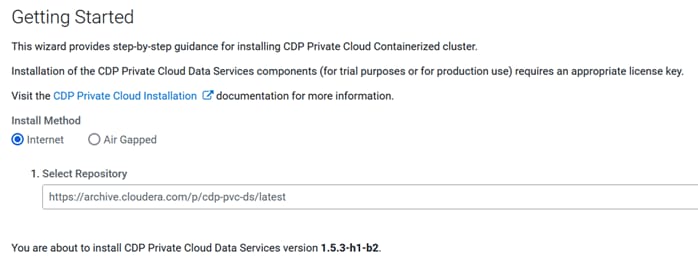
Step 20. From the Cluster Basics page, entera name for the Private Cloud cluster. From the Base Cluster drop-down list, select the cluster that has the storage and SDX services that you want this new Private Cloud Data Services instance to connect with. Click Continue.
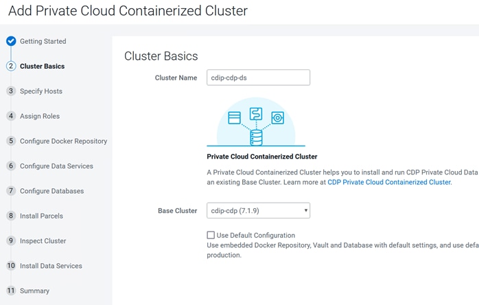
Step 21. From the Specify Hosts page, hosts that have already been added to Cloudera Manager are listed on the Currently Managed Hosts tab and/or add new hosts. Select one or more of these hosts to add to the ECS cluster. Click Continue.
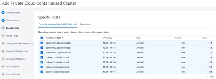
Step 22. From the Assign Roles page, you can customize the roles assignment for your new Private Cloud Containerized cluster. Single node ECS installation is supported but is only intended to enable CDSW to CML migration. If you are installing ECS on a single node, only the Docker and ECS Server roles are assigned. The ECS Agent role is not required for single node installation.
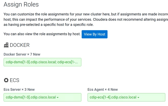
Note: With 3 mgmt nodes and 4 worker nodes for CDP Data Services ECS cluster, select the following host role assignments:
● Docker server – cdip-dsms[1-3], cdip-ecs[1-4] #All ECS nodes
● ECS Server – cdip-dsms[1-3] #ECS master node only
● ECS Agent – cdip-ecs[1-4] # ECS worker node only
Note: Cloudera does not recommend altering assignments unless you have specific requirements such as having selected a specific host for a specific role.
Step 23. Configure a Docker Repository. There are several options for configuring a Docker Repository. For more information, see Docker repository access.
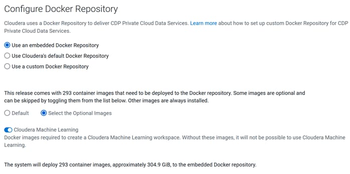
Note: Embedded Repository can be a single point of failure. If the node that runs the Docker Repository fails or becomes unavailable, some cluster functionalities might become unavailable. Moving the Docker Repository to another node is a complex process and will require engaging Cloudera Professional Services.
Note: Cloudera Repository option is best suited for proof-of-concept, non-production deployments or deployments that do not have security requirements that disallow internet access. This option requires that cluster hosts have access to the internet, and installation method selected as Internet.
Step 24. From the Configure Data Services page, modify the configuration as appropriate. Edit Application domain to match “app.example.com.” For example, in this solution we configure AD Domain Services with “cdip.cisco.local” for the domain name and created a wildcard entry “*.apps.cdip.cisco.local.” Click Continue.
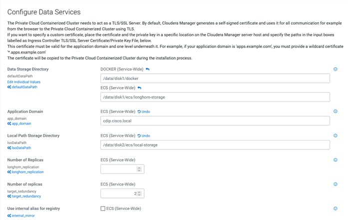
Note: Review the range of cluster IP and service IP as part of the ECS installation. It might conflict with the existing network configuration. Adjust the range of IPs to be configured. Consult with the network team to avoid a potential conflict.
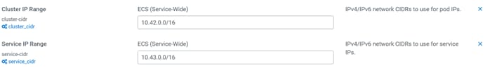
Step 25. Configure the Databases page, edit the size for the Embedded Database Disk Space. Click Continue.
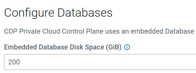
Step 26. From the Install Parcels page, the selected parcel is downloaded to the Cloudera Manager server host, distributed, unpacked, and activated on the ECS cluster hosts. Click Continue.
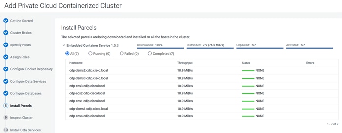
Step 27. From the Inspect Cluster page, you can inspect your network performance and hosts. Click Review Inspector Result. Click Continue.
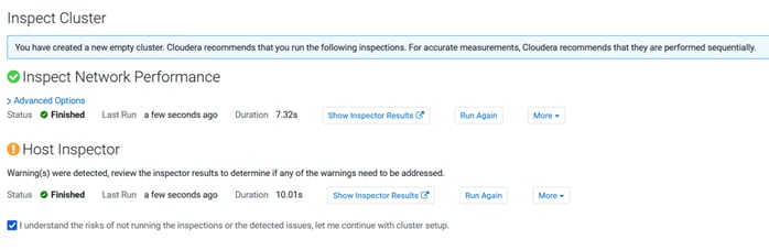
Note: It’s safe to ignore the unrelated error in the host inspector result. For example, the hosts in a Private Cloud Containerized Cluster that have GPUs are required to have NVIDIA Drivers and Nvidia-container-runtime installed. The following hosts do not satisfy this requirement: cdip-dsms[1-3].cdip.cisco.local
Since all hosts part of the ECS installation might not have NVIDIA GPU installed and Nvidia driver and Nvidia container-runtime is not installed on non-GPU node(s). It is safe to ignore the warning and check the box to continue with ECS installation.
Note: Install Data Services can take several hours. The copying operation for Docker repository may take 4 – 5 hours.
Step 28. Install Data Services step will run set of first run commands and report status on Data Services installation.
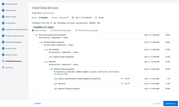
Step 29. When the installation is complete, you will see the Summary image. You can now launch CDP Private Cloud.
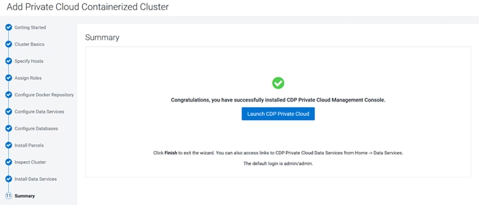
Note: Run # kubectl get pods -A to review all pods and their status as either running or completed.
Note: If nvgfd-gpu-feature-discovery-xxxx pods remain in crashlookbackoff please apply patch to fix the issue.
# kubectl patch clusterrolebinding gpu-feature-discovery -p ‘{“subjects”:[{“kind”:”ServiceAccount”,”name”:”gpu-feature-discovery”,”namespace”:”kube-system”}]}’
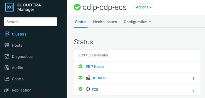
Step 30. When the installation is complete, you can access your Private Cloud Data Services instance from Cloudera Manager. Click Data Services, then click Open Private Cloud Data Services for the applicable Data Services cluster.
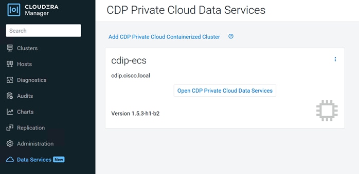
Step 31. Login to CDP Private Cloud Data Services as local administrator: admin/admin
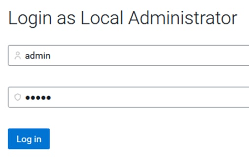
Step 32. Click Management Console.
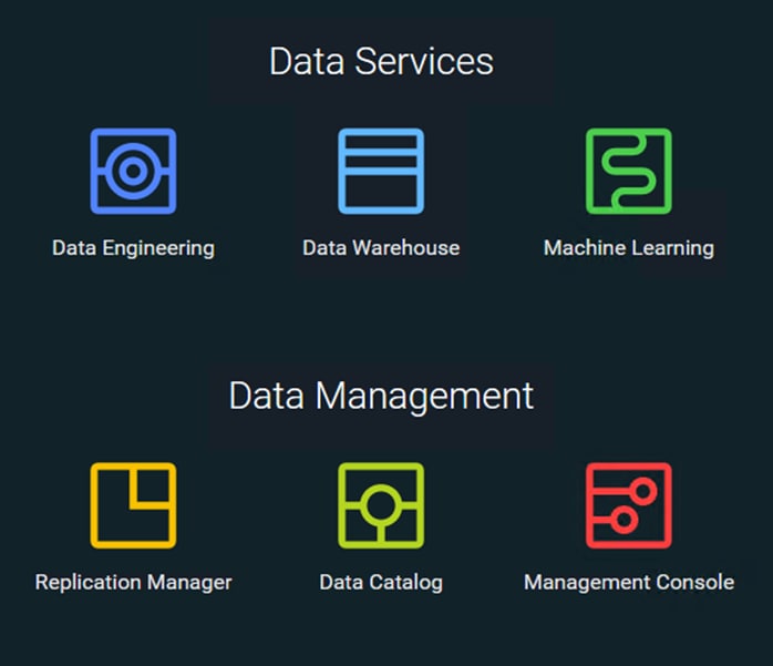
The User Management tab allows you to add or the update role on existing users. The Groups tab allows you to sync user group from active directory to access CDP Data Services.
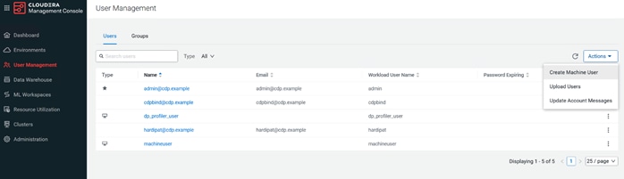
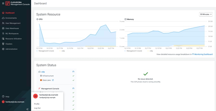
For more details about Cloudera Private Cloud Management console, go to: https://docs.cloudera.com/management-console/1.5.3/index.html?
Cloudera Data Platform Private Cloud Machine Learning
Cloudera’s platform for machine learning and AI, is available as Cloudera Machine Learning (CML) on CDP Private Cloud. Cloudera Machine Learning unifies self-service data science and data engineering in a single, portable service as part of an enterprise data cloud for multi-function analytics on data anywhere.
Organizations can now build and deploy machine learning and AI capabilities for business at scale, efficiently and securely. Cloudera Machine Learning on Private Cloud is built for the agility and power of cloud computing but operates inside your private and secure data center.
Data Scientists are the key users of Cloudera Machine Learning. Data Scientists can use CML to explore data, develop models, and deploy models into production. In this section, you can find information on all of the tasks you perform as part of the Machine Learning Lifecycle.
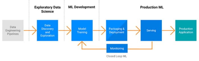
For more information, go to: CDP Private Cloud Machine Learning.
Review the requirements page for ECS and get started with CML on Private Cloud: https://docs.cloudera.com/machine-learning/1.5.3/private-cloud-requirements/index.html
For more information about CML workspace and how to steps, go to: https://docs.cloudera.com/machine-learning/cloud/workspaces/topics/ml-provision-workspaces.html
Procedure 1. Get started with CML
Step 1. From the Cloudera Private Cloud console, go to Cloudera Machine Learning.
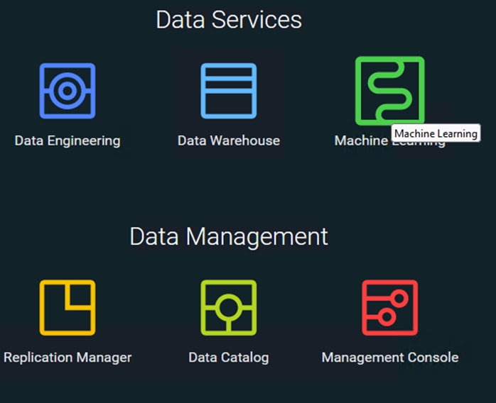
Step 2. First time login requires to provision a workspace.
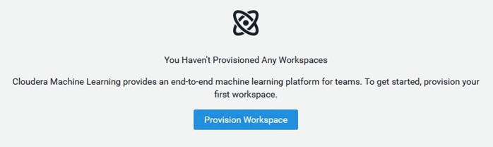
Step 3. Provide input required to provision machine learning workspace. Click Provision Workspace.
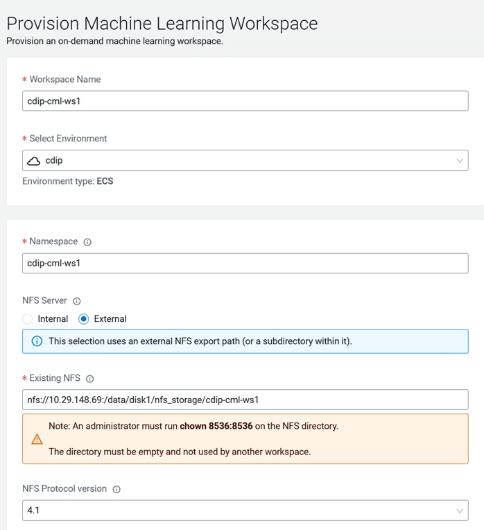
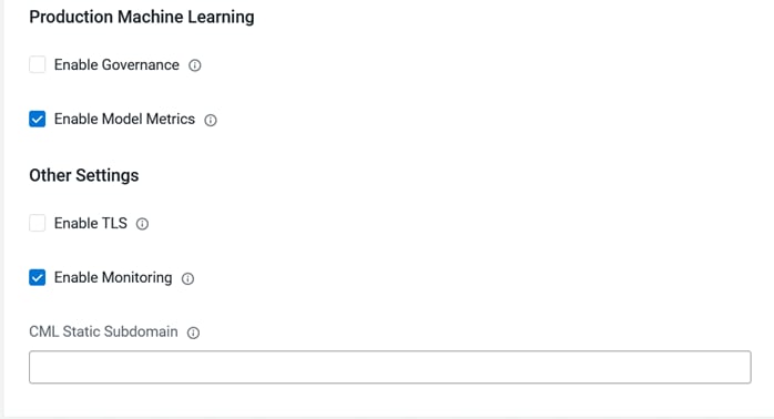
Note: Click the i icon to get more information on the field.
Step 4. When provisioning of workspace is completed the status reports as Ready.
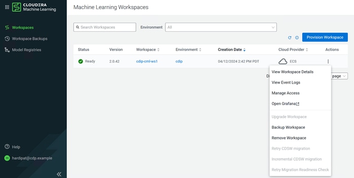
Step 5. Click Manage Access.
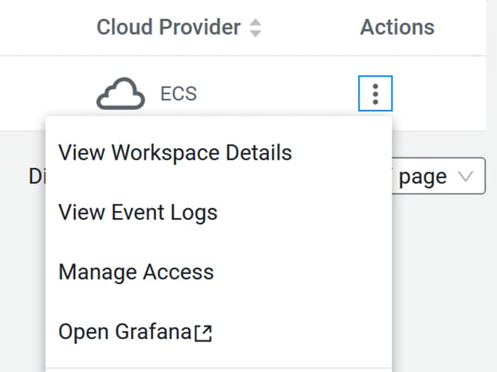
Step 6. In the search field search for user or group to be access to access Machine Learning workspace.
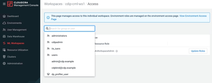
Step 7. Update the Resource role for user or group selected to manage access to workspace provisioned in Cloudera Machine Learning.
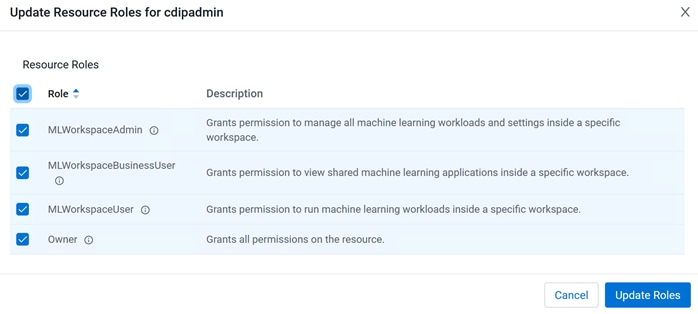
Step 8. Click the created workspace name.
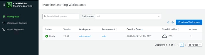
Step 9. CML workspace WebUI overview.
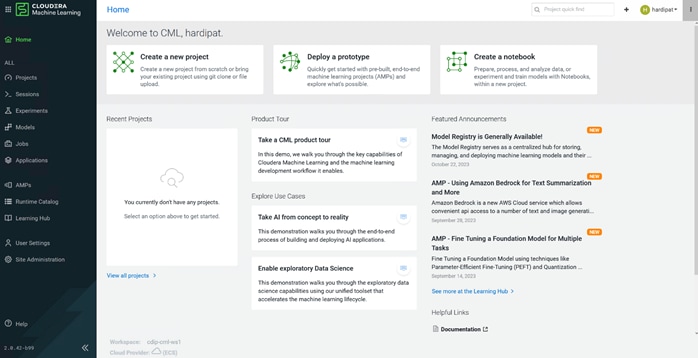
Step 10. Click the Projects tab, expand View Resource Usage Details to review available resources.
Note: For more information and how to review projects section in ML workspace, go to: https://docs.cloudera.com/machine-learning/cloud/projects/index.html
Step 11. Enter project name and select type of initial setup.
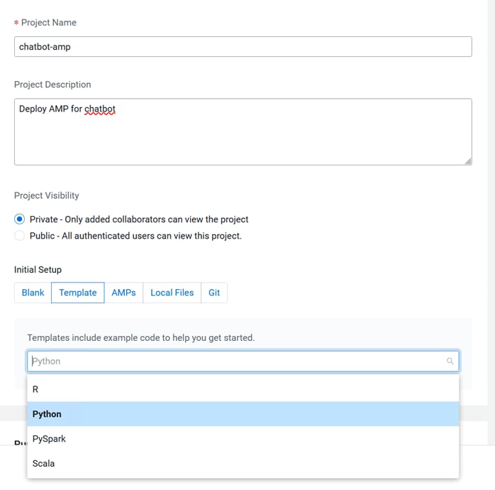
Step 12. Select Runtime setup and check the box to add GPU enabled Runtime variant if applicable.
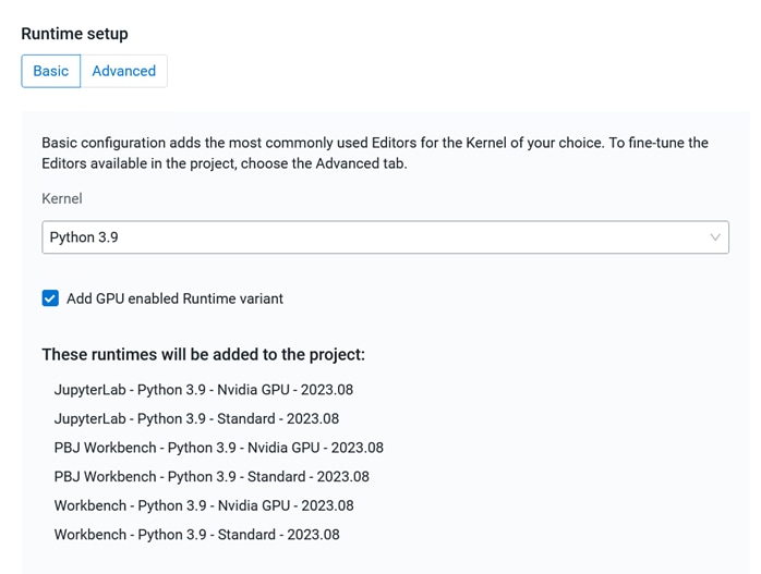
Step 13. Click Create Project.
Step 14. Click the Sessions tab and enter details for new session.
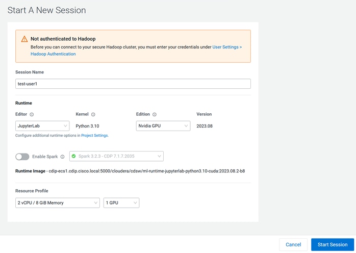
Step 15. To access data from Hadoop cluster go to User > User Settings > Hadoop authentication. Enter username@DOMAIN.LOCAL/<Password>.
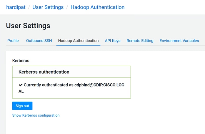
Step 16. Go to Site Administration to edit Resource profile and GPU per session/ Job.
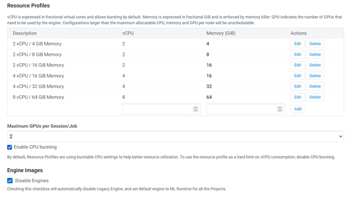
Note: Deploying and documentation of every aspect of CML workspace, project, and user management is not explained in this document. Refer to the related Cloudera documentation on Cloudera Machine Learning How to section for more details: https://docs.cloudera.com/machine-learning/cloud/product/topics/ml-product-overview.html
Step 17. Go to the AMPs tab to get started with pre-built Accelerators for Machine Learning Projects.
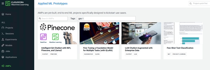
Step 18. Select desired AMP and click on Configure Project.
Step 19. For example, select Intelligent QA Chatbot with NiFi, Pinecone and Llama2 AMP, Click Configure Project. After editing Runtime field for new project, click on Launch Project. Go to the github link for the recommendation on Runtime and minimum versions required.
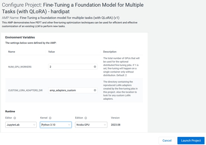
AMP demonstrating demonstrates how to use an open-source pre-trained instruction-following LLM (Large Language Model) to build a Chatbot-like web application. The responses of the LLM are enhanced by giving it context from an internal knowledge base. This context is retrieved by using an open-source Vector Database to do semantic search.
Step 20. Intelligent QA Chatbot with NiFi, Pinecone, and Llama2 – AMP project overview.
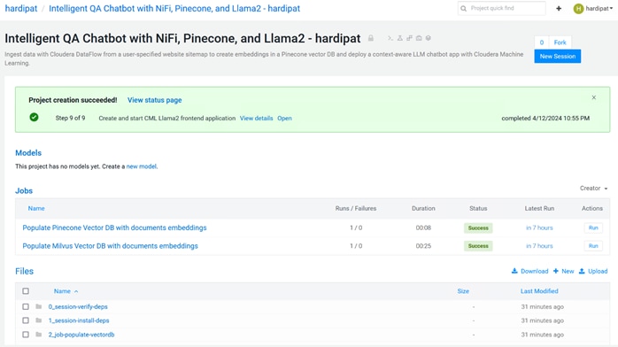
Step 21. Create a new session with desired resources, editor, kernel, and number of GPUs.
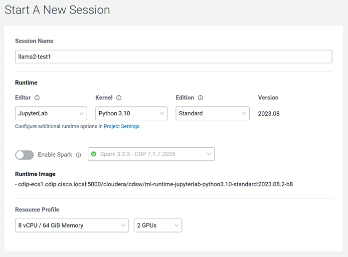
Jupyter notebook session in CML.
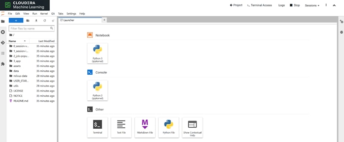
Step 22. Eit found_htmls.txt in “/Build_Your_Own_Knowledge_Base_Tools/Python-based_sitemap_scrape/” to include with URLs desired to customize with.
Step 23. Run “!pip3 install -r USER_START_HERE/Build_Your_Own_Knowledge_Base_Tools/Python-based_sitemap_scrape/requirements.txt” to install requirements.
Step 24. Run “2_kb_html_to_text.py” script to convert html documents to .text format.
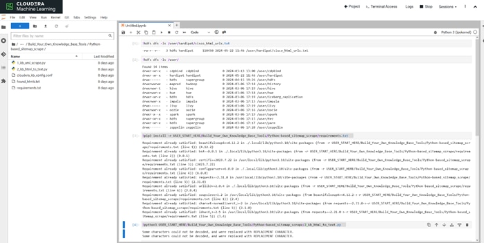
Step 25. Alternatively, click Run actions for HTML to Text and then Populate Vector DB with documents embeddings from project in CML WebUI.
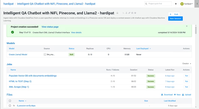
Step 26. Click the Applications tab to open the Web Interface for Llama2 chatbot.
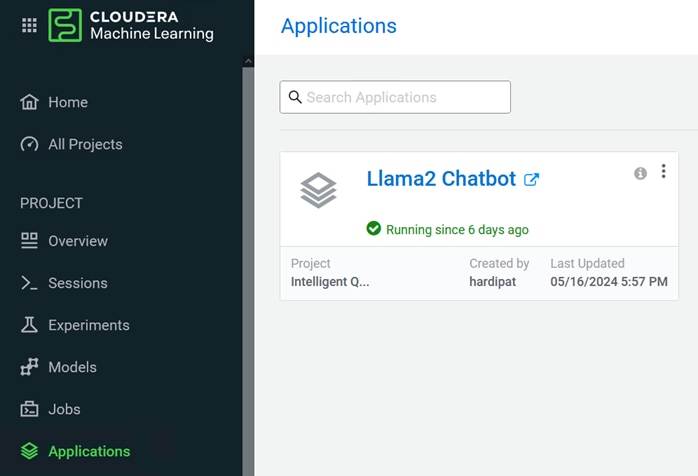
Step 27. Change additional input parameters for temperature (randomness of response), number of tokens (length of response) and vector database choice or with default settings.
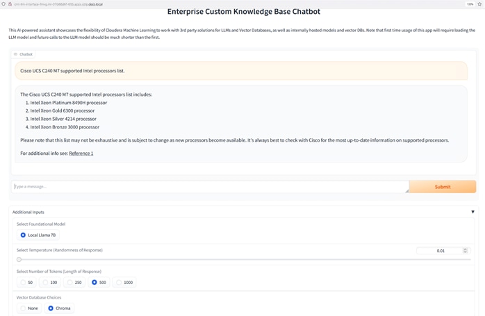
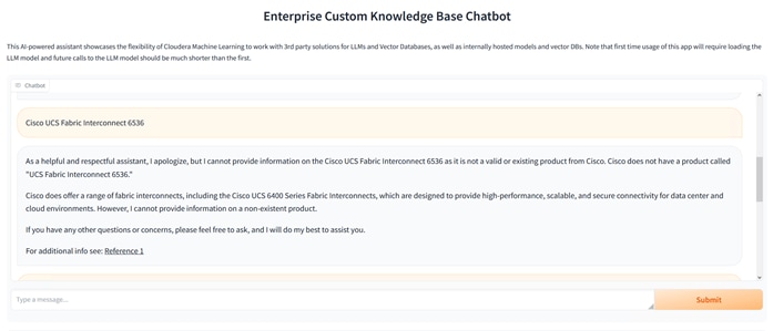
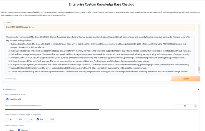
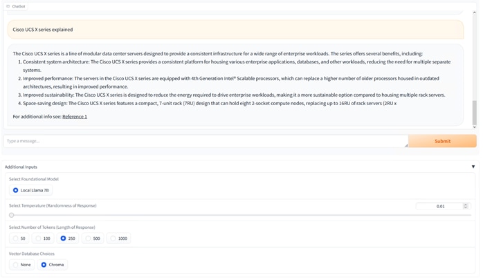
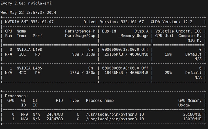
Use case: This allows to enterprises to convert their own proprietary data into custom knowledge base for fast retrieval of relevant content. For example:
● Automated responses and 24/7 availability to inquiries, reducing load and improve support received.
● Internal employee support, HR assistance, IT support etc.
● For sales and marketing, provide detailed information on product and services.
● Operation efficiency through internal knowledge base, faster document retrieval, maintain compliance and improved productivity.
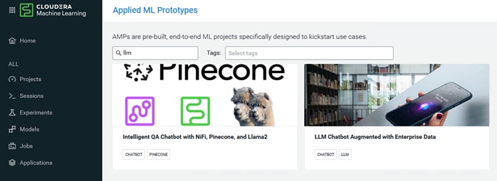
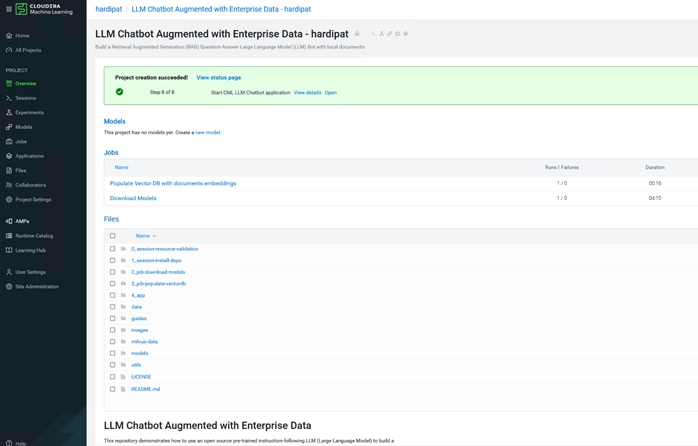
This repository demonstrates how to use an open-source pre-trained instruction-following LLM (Large Language Model) to build a Chatbot-like web application. The responses of the LLM are enhanced by giving it context from an internal knowledge base. This context is retrieved by using an open source Vector Database to do semantic search.
Step 28. Add additional test for customized data test, Run Populate Vector DB with documents embeddings.
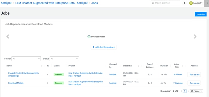
Step 29. Click Applications to launch CML LLM Chatbot.
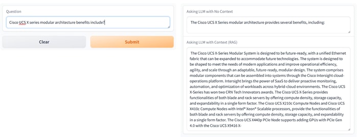
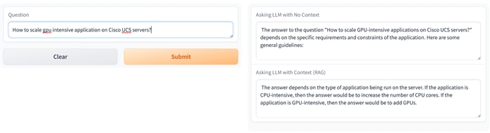
Use cases: chatbot web application based on the open-source pre-trained LLM. When a use asks a question there two responses generated; one based on the non factual non context and another is based on the user query that is submitted to Milvus Vector Database embedded in the AMP which search for result in knowledge-base and response provided based on the documents that are semantically closest to user’s question through the process of RAG (Retrieval Augmented Generation).
By implementing RAG based context oriented responses in chatbot minimizes the risk associated with false or hallucinated information in enterprises such as:
● Patient support in healthcare
● Customer inquiry or product query/recommendation in Finance, Retail etc.
● Equipment maintenance or how to in manufacturing
● Legal
● Personalized recommendations for tourism
Education
Note: The quality of the chatbot response depends on organized and clean data.
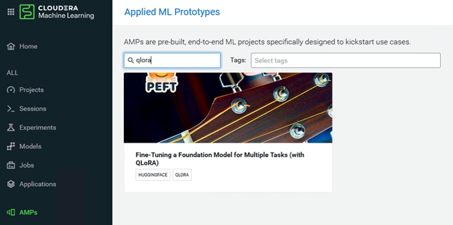
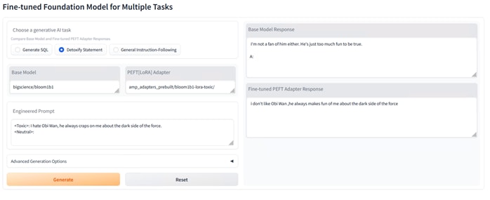
Use cases: The AMP demonstrates implementation of LLM fine-tuning jobs that make use of the QLoRA and Accelerate implementations available in the PEFT open-source library from Huggingface and an example application that swaps the fine-tuned adapters in real time for inference targeting different tasks.
Targeted for specific tasks and problems which requires domain-specific expertise and terminology. For example:
● Customer service automation and sentiment analysis
● predictive maintenance and quality control in Manufacturing
● Fraud detection and predictive analytics in Finance
● Legal search and document review
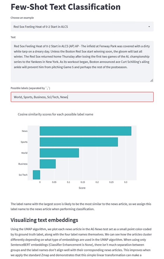
Use cases: Few shot text classification leverages machine learning models to classify text into different categories with very few training examples. When labeled data is scarce and expensive to obtain Zero or Few Shot learning can be useful such as:
● HealthCare - Patient medical records or clinical notes into various medical categories such as diagnosis, treatment plans, and medication.
● Finance - Financial transactions into categories such as groceries, utilities, entertainment, etc.
● Legal - Categorize legal documents into different types such as contracts, court orders, legal briefs, and compliance documents.
● Retail - Customer feedback or reviews into categories like positive, negative, or neutral sentiments, or specific topics like product quality, delivery service, and customer support.
● Human Resources - Categorize resumes into different job roles or skill sets such as software development, marketing, sales, and HR.
● Education - Student assignments or essays into topics such as mathematics, science, history, and literature.
● Manufacturing - Incident reports or maintenance logs into categories such as equipment failure, safety incidents, and routine maintenance.
● Telecommunications - Customer support queries into different categories such as billing issues, technical support, and service requests.
● Energy and Utilities - Energy usage reports or logs into categories such as residential, commercial, and industrial usage.
● Media and Entertainment - Media content classification such as articles, videos, and social media posts into categories like news, sports, entertainment, and technology.
Cisco Data Intelligence Platform (CDIP) leveraging Cisco's compute and network solutions with Cloudera Data Platform (CDP) Private Cloud provides an integrated and scalable architecture for data lakes, private cloud infrastructure, and Generative AI use cases. Cloud-Based, high-performance, and scalable infrastructure to support increasing data and model complexity on-demand. Hybrid solution to offer flexibility and cost-efficiency through optimized resource utilization.
● Cisco Intersight for centralized management of Cisco UCS server provides automated hardware provisioning, monitoring, and analytics to efficiently deploy and scale AI workloads.
● Optimized data transfer to ensure data movement in various stages of the workflow such as data ingestion, pre-processing and processing, model training and inference, feedback loop for retraining and/or model improvement: CDIP may involve content delivery to global audiences, requiring optimized data transfer mechanisms.
● Distributed storage system for parallel data processing while ensuring data availability, model training consistency and preservation, reduce downtime by backup and replication in case of data loss or corruption.
● Cloudera Private Cloud integrates seamlessly with popular AI frameworks and tools such as TensorFlow, PyTorch, Apache Spark MLlib; developers can run their favorite AI frameworks without any modifications, leveraging its scalability and resource management capabilities.
● Disaggregated compute and storage architecture supports heterogeneous workloads more effectively. Different types of compute nodes can be tailored to specific tasks, such as GPU-accelerated nodes for model training and CPU-only nodes for inference. Similarly, different types of storage nodes can be optimized for performance, capacity, or cost.
● Ensure compliance with data regulations and standards through data governance. This involves implementing policies for data storage, access control, and audit trails to ensure regulatory compliance.
● Energy-efficient Cisco UCS Server to reduce operational cost and contribute to environmental sustainability.
In conclusion, this integrated approach empowers enterprises to derive actionable insights, drive innovation, and maintain a competitive edge in today's data-driven world.
About the Author
Hardik Patel, Technical Marketing Engineer, Cloud and Compute Product Group, Cisco Systems, Inc.
Hardik Patel is a Solution Architect in Cisco System’s Cloud and Compute Engineering Group. Hardik has over 15 years of experience in datacenter solutions and technologies. He is currently responsible for design and architect of next-gen infrastructure solution and performance in AI/ML and analytics. Hardik holds a Master of Science degree in Computer Science with various career-oriented certification in virtualization, network, and Microsoft.
Acknowledgements
For their support and contribution to the design, validation, and creation of this Cisco Validated Design, the author would like to thank:
● Tushar Patel, Distinguished Technical Marketing Engineer, Cloud and Compute Product Group, Cisco Systems, Inc.
● Tarun Dave, Sr. Partner Solutions Engineer, Cloudera
● Ali Bajwa, Sr. Director, Partner Solution Engineering, Cloudera
● Kenton Troy Davis, Manager, Partner Solution Engineering, Cloudera
● Chuck Levesque, Principal Sales Engineer, Cloudera
Appendix
This appendix contains the following:
● Appendix A – Bill of Materials
● Appendix B - References used in this guide
● Appendix C – Recommended for You
Appendix A – Bill of Materials
Table 7. Bill of Material for Cisco UCS C240 M7SX – CDP Private Cloud Base Cluster
| Part Number |
Description |
Qty |
| UCS-M7-MLB |
UCS M7 RACK MLB |
1 |
| DC-MGT-SAAS |
Cisco Intersight SaaS |
1 |
| DC-MGT-IS-SAAS-AD |
Infrastructure Services SaaS/CVA - Advantage |
8 |
| SVS-DCM-SUPT-BAS |
Basic Support for DCM |
1 |
| DC-MGT-UCSC-1S |
UCS Central Per Server - 1 Server License |
8 |
| DC-MGT-ADOPT-BAS |
Cisco Intersight - 3 virtual adoption sessions (Once Only) |
1 |
| UCSC-C240-M7SN |
UCS C240 M7 Rack w/o CPU, mem, drives, 2U 24 NVMe backplane |
8 |
| CON-L1NCO-UCSCC25M |
CX LEVEL 1 8X7XNCDOS UCS C240 M7 Rack w/o CPU, mem, drives, |
8 |
| UCSC-GPUAD-C240M7 |
GPU AIR DUCT FOR C240M7 |
8 |
| UCSC-M-V5D200G-D |
Cisco VIC 15238 2x 40/100/200G mLOM C-Series |
8 |
| UCS-M2-960G-D |
960GB M.2 SATA Micron G2 SSD |
16 |
| UCS-M2-HWRAID-D |
Cisco Boot optimized M.2 Raid controller |
8 |
| UCSX-TPM-002C-D |
TPM 2.0, TCG, FIPS140-2, CC EAL4+ Certified, for servers |
8 |
| UCSC-RAIL-D |
Ball Bearing Rail Kit for C220 & C240 M7 rack servers |
8 |
| CIMC-LATEST-D |
IMC SW (Recommended) latest release for C-Series Servers. |
8 |
| UCSC-HSLP-C220M7 |
UCS C220 M7 Heatsink for & C240 GPU Heatsink |
16 |
| UCSC-BBLKD-M7 |
UCS C-Series M7 SFF drive blanking panel |
96 |
| UCS-DDR5-BLK |
UCS DDR5 DIMM Blanks |
128 |
| UCSC-RISAB-24XM7 |
UCS C-Series M7 2U Air Blocker GPU only |
24 |
| UCSC-M2EXT-240-D |
C240M7 2U M.2 Extender board |
8 |
| UCS-CPU-I6448H |
Intel I6448H 2.4GHz/250W 32C/60MB DDR5 4800MT/s |
16 |
| UCS-MRX32G1RE1 |
32GB DDR5-4800 RDIMM 1Rx4 (16Gb) |
128 |
| UCSC-RIS1C-24XM7 |
UCS C-Series M7 2U Riser 1C PCIe Gen5 (2x16) |
8 |
| UCSC-RIS2C-24XM7 |
UCS C-Series M7 2U Riser 2C PCIe Gen5 (2x16) (CPU2) |
8 |
| UCSC-RIS3C-240-D |
C240 M7 Riser 3C |
8 |
| UCS-NVMEG4-M3840D |
3.8TB 2.5in U.3 15mm P7450 Hg Perf Med End NVMe |
96 |
| UCSC-PSU1-2300W-D |
Cisco UCS 2300W AC Power Supply for Rack Servers Titanium |
16 |
| CAB-C19-CBN |
Cabinet Jumper Power Cord, 250 VAC 16A, C20-C19 Connectors |
16 |
| RHEL-2S2V-D3S |
Red Hat Enterprise Linux (1-2 CPU,1-2 VN); Prem 3Yr SnS Reqd |
4 |
| RHEL-2S2V-D3YR |
Red Hat Enterprise Linux Premium 24x7 - 3Yr SnS |
4 |
Table 8. Bill of Material for Cisco UCS X210c M7 compute node – CDP Private Cloud Data Services
| Part Number |
Description |
Qty |
| UCSX-M7-MLB |
UCSX M7 Modular Server and Chassis MLB |
1 |
| DC-MGT-SAAS |
Cisco Intersight SaaS |
1 |
| DC-MGT-UCSC-1S |
UCS Central Per Server - 1 Server License |
4 |
| DC-MGT-ADOPT-BAS |
Cisco Intersight - 3 virtual adoption sessions (Once Only) |
1 |
| SVS-DCM-SUPT-BAS |
Basic Support for DCM |
1 |
| DC-MGT-IS-SAAS-AD |
Infrastructure Services SaaS/CVA - Advantage |
4 |
| UCSX-9508-D-U |
UCS 9508 Chassis Configured |
1 |
| CON-L1NCO-UCSX9958 |
CX LEVEL 1 8X7XNCDOS UCS 9508 Chassis Configured |
1 |
| UCSX-I9108-100G-D |
UCS 9108-100G IFM for 9508 Chassis |
2 |
| UCSX-F-9416-D |
UCS 9416 X-Fabric module for 9508 chassis |
2 |
| UCSX-CHASSIS-SW-D |
Platform SW (Recommended) latest release for X9500 Chassis |
1 |
| UCSX-9508-CAK-D |
UCS 9508 Chassis Accessory Kit |
1 |
| UCSX-9508-ACPEM-D |
UCS 9508 Chassis Rear AC Power Expansion Module |
2 |
| UCSX-9508-KEYAC-D |
UCS 9508 AC PSU Keying Bracket |
1 |
| UCSX-210C-M7 |
UCS 210c M7 Compute Node w/o CPU, Memory, Storage, Mezz |
4 |
| CON-L1NCO-UCSXM21C |
CX LEVEL 1 8X7XNCDOS UCS 210c M7 Compute Node w o CPU, Memory |
4 |
| UCSX-ML-V5D200G-D |
Cisco VIC 15231 2x 100G mLOM X-Series |
4 |
| UCSX-V4-PCIME-D |
UCS PCI Mezz card for X-Fabric |
4 |
| UCSX-M2-960G-D |
960GB 2.5in M.2 SATA Micron G2 SSD |
8 |
| UCSX-C-SW-LATEST-D |
Platform SW (Recommended) latest release X-Series ComputeNode |
4 |
| UCSX-TPM-002C-D |
TPM 2.0, TCG, FIPS140-2, CC EAL4+ Certified, for servers |
4 |
| UCSX-C-M7-HS-F |
UCS X210c M7 Compute Node Front CPU Heat Sink |
4 |
| UCSX-C-M7-HS-R |
UCS X210c M7 Compute Node Rear CPU Heat Sink |
4 |
| UCSX-M2-HWRD-FPS |
UCSX Front panel with M.2 RAID controller for SATA drives |
4 |
| UCS-DDR5-BLK |
UCS DDR5 DIMM Blanks |
64 |
| UCSC-BBLKD-M7 |
UCS C-Series M7 SFF drive blanking panel |
8 |
| UCSX-CPU-I6448H |
Intel I6448H 2.4GHz/250W 32C/60MB DDR5 4800MT/s |
8 |
| UCSX-MRX64G2RE1 |
64GB DDR5-4800 RDIMM 2Rx4 (16Gb) |
64 |
| UCSX-X10C-PT4F-D |
UCS X10c Compute Pass Through Controller (Front) |
4 |
| UCSX-NVME4-3840-D |
3.8TB 2.5in U.2 15mm P5520 Hg Perf Med End NVMe |
16 |
| UCSX-440P-D |
UCS X-Series Gen4 PCIe node |
4 |
| UCSX-RIS-A-440P-D |
Riser A for 1x dual slot GPU per riser, 440P PCIe node |
8 |
| UCSX-GPU-H100-80 |
NVIDIA H100: 350W, 80GB, 2-slot FHFL GPU |
8 |
| RHEL-2S2V-D3S |
Red Hat Enterprise Linux (1-2 CPU,1-2 VN); Prem 3Yr SnS Reqd |
4 |
| RHEL-2S2V-D3YR |
Red Hat Enterprise Linux Premium 24x7 - 3Yr SnS |
4 |
| UCSX-PSU-2800AC-D |
UCS 9508 Chassis 2800V AC Dual Voltage PSU Titanium |
6 |
| CAB-C19-CBN |
Cabinet Jumper Power Cord, 250 VAC 16A, C20-C19 Connectors |
6 |
Table 9. Bill of Material for Cisco UCS Fabric Interconnect
| Part Number |
Description |
Qty |
| UCSX-FI-6536-D-U |
Fabric Interconnect 6536 for IMM |
2 |
| CON-L1NCO-UCSX00F6 |
CX LEVEL 1 8X7XNCDOS Fabric Interconnect 6536 for IMM |
2 |
| N10-MGT018-D |
UCS Manager v4.2 and Intersight Managed Mode v4.2 |
2 |
| UCS-FI-6500-SW |
Perpetual SW License for the 6500 series Fabric Interconnect |
2 |
| UCS-PSU-6536-AC-D |
UCS 6536 Power Supply/AC 1100W PSU - Port Side Exhaust |
4 |
| CAB-N5K6A-NA |
Power Cord, 200/240V 6A North America |
4 |
| QSFP-100G-AOC3M |
100GBASE QSFP Active Optical Cable, 3m |
24 |
| UCS-ACC-6536-D |
UCS 6536 Chassis Accessory Kit |
2 |
| UCS-FAN-6536-D |
UCS 6536 Fan Module |
12 |
Table 10. Bill of Material for Cisco Nexus 93600CD-GX switch
| Part Number |
Description |
Qty |
| N9K-C93600CD-GX |
Nexus 9300 with 28p 100G and 8p 400G |
2 |
| CON-SNC-N9KC936G |
SNTC-NCD Nexus 9300 with 28p 100G and 8p 400G |
2 |
| NXK-AF-PI |
Dummy PID for Airflow Selection Port-side Intake |
2 |
| MODE-NXOS |
Mode selection between ACI and NXOS |
2 |
| NXOS-9.3.10 |
Nexus 9500, 9300, 3000 Base NX-OS Software Rel 9.3.10 |
2 |
| NXK-ACC-KIT-1RU |
Nexus 3K/9K Fixed Accessory Kit, 1RU front and rear removal |
2 |
| NXA-FAN-35CFM-PI |
Nexus Fan, 35CFM, port side intake airflow |
12 |
| NXA-PAC-1100W-PI2 |
Nexus AC 1100W PSU - Port Side Intake |
4 |
| CAB-C13-C14-AC |
Power cord, C13 to C14 (recessed receptacle), 10A |
4 |
Appendix B – References used in this guide
Cisco Infrastructure Solution for Data Analytics: https://www.cisco.com/c/en/us/solutions/data-center-virtualization/big-data/index.html
Design Zone for Cisco Data Intelligence Platform: https://www.cisco.com/c/en/us/solutions/design-zone/data-center-design-guides/data-center-big-data.html
Cloudera Private Cloud Base Getting Started Guide: https://docs.cloudera.com/cdp-private-cloud/latest/index.html
Cloudera Private Cloud Data Services Getting Started Guide: https://docs.cloudera.com/cdp-private-cloud-data-services/latest/index.html
CDP Private Cloud Machine Learning Overview: https://docs.cloudera.com/machine-learning/1.5.3/index.html
CDP Private Cloud Data Engineering Overview: https://docs.cloudera.com/data-engineering/1.5.3/index.html
CDP Private Cloud Data Warehouse Overview: https://docs.cloudera.com/data-warehouse/1.5.3/index.html
Appendix C – Recommended for You
To find out more about Cisco UCS Big Data solutions, go to: https://www.cisco.com/go/bigdata
To find out more about Cisco UCS Big Data validated designs, go to: https://www.cisco.com/go/bigdata_design
To find out more about Cisco Data Intelligence Platform, go to: https://www.cisco.com/c/dam/en/us/products/servers-unified-computing/ucs-c-series-rack-servers/solution-overview-c22-742432.pdf
To find out more about Cisco UCS AI/ML solutions, go to: http://www.cisco.com/go/ai-compute
To find out more about Cisco ACI solutions, go to: http://www.cisco.com/go/aci
To find out more about Cisco validated solutions based on Software Defined Storage, go to: https://www.cisco.com/c/en/us/solutions/data-center-virtualization/software-defined-storage-solutions/index.html
Cloudera Data Platform Private Cloud latest release note, go to: https://docs.cloudera.com/cdp-private-cloud-upgrade/latest/release-guide/topics/cdpdc-release-notes-links.html
Cloudera Data Platform Private Cloud Base Requirements and Supported Versions, go to: https://docs.cloudera.com/cdp-private-cloud-upgrade/latest/release-guide/topics/cdpdc-requirements-supported-versions.html
Cloudera Data Platform Private Cloud Data Services installation on Embedded Container Service requirements and supported versions, go to: https://docs.cloudera.com/cdp-private-cloud-data-services/1.5.3/index.html
For comments and suggestions about this guide and related guides, join the discussion on Cisco Community at https://cs.co/en-cvds.
CVD Program
ALL DESIGNS, SPECIFICATIONS, STATEMENTS, INFORMATION, AND RECOMMENDATIONS (COLLECTIVELY, "DESIGNS") IN THIS MANUAL ARE PRESENTED "AS IS," WITH ALL FAULTS. CISCO AND ITS SUPPLIERS DISCLAIM ALL WARRANTIES, INCLUDING, WITHOUT LIMITATION, THE WARRANTY OF MERCHANTABILITY, FITNESS FOR A PARTICULAR PURPOSE AND NONINFRINGEMENT OR ARISING FROM A COURSE OF DEALING, USAGE, OR TRADE PRACTICE. IN NO EVENT SHALL CISCO OR ITS SUPPLIERS BE LIABLE FOR ANY INDIRECT, SPECIAL, CONSEQUENTIAL, OR INCIDENTAL DAMAGES, INCLUDING, WITHOUT LIMITATION, LOST PROFITS OR LOSS OR DAMAGE TO DATA ARISING OUT OF THE USE OR INABILITY TO USE THE DESIGNS, EVEN IF CISCO OR ITS SUPPLIERS HAVE BEEN ADVISED OF THE POSSIBILITY OF SUCH DAMAGES.
THE DESIGNS ARE SUBJECT TO CHANGE WITHOUT NOTICE. USERS ARE SOLELY RESPONSIBLE FOR THEIR APPLICATION OF THE DESIGNS. THE DESIGNS DO NOT CONSTITUTE THE TECHNICAL OR OTHER PROFESSIONAL ADVICE OF CISCO, ITS SUPPLIERS OR PARTNERS. USERS SHOULD CONSULT THEIR OWN TECHNICAL ADVISORS BEFORE IMPLEMENTING THE DESIGNS. RESULTS MAY VARY DEPENDING ON FACTORS NOT TESTED BY CISCO.
CCDE, CCENT, Cisco Eos, Cisco Lumin, Cisco Nexus, Cisco StadiumVision, Cisco TelePresence, Cisco WebEx, the Cisco logo, DCE, and Welcome to the Human Network are trademarks; Changing the Way We Work, Live, Play, and Learn and Cisco Store are service marks; and Access Registrar, Aironet, AsyncOS, Bringing the Meeting To You, Catalyst, CCDA, CCDP, CCIE, CCIP, CCNA, CCNP, CCSP, CCVP, Cisco, the Cisco Certified Internetwork Expert logo, Cisco IOS, Cisco Press, Cisco Systems, Cisco Systems Capital, the Cisco Systems logo, Cisco Unified Computing System (Cisco UCS), Cisco UCS B-Series Blade Servers, Cisco UCS C-Series Rack Servers, Cisco UCS S-Series Storage Servers, Cisco UCS X-Series, Cisco UCS Manager, Cisco UCS Management Software, Cisco Unified Fabric, Cisco Application Centric Infrastructure, Cisco Nexus 9000 Series, Cisco Nexus 7000 Series. Cisco Prime Data Center Network Manager, Cisco NX-OS Software, Cisco MDS Series, Cisco Unity, Collaboration Without Limitation, EtherFast, EtherSwitch, Event Center, Fast Step, Follow Me Browsing, FormShare, GigaDrive, HomeLink, Internet Quotient, IOS, iPhone, iQuick Study, LightStream, Linksys, MediaTone, MeetingPlace, MeetingPlace Chime Sound, MGX, Networkers, Networking Academy, Network Registrar, PCNow, PIX, PowerPanels, ProConnect, ScriptShare, SenderBase, SMARTnet, Spectrum Expert, StackWise, The Fastest Way to Increase Your Internet Quotient, TransPath, WebEx, and the WebEx logo are registered trade-marks of Cisco Systems, Inc. and/or its affiliates in the United States and certain other countries. (LDW_P2)
All other trademarks mentioned in this document or website are the property of their respective owners. The use of the word partner does not imply a partnership relationship between Cisco and any other company. (0809R)