FlashStack Cisco UCS X-Series and Pure Storage for Citrix Virtual Apps and Desktops
Available Languages
Bias-Free Language
The documentation set for this product strives to use bias-free language. For the purposes of this documentation set, bias-free is defined as language that does not imply discrimination based on age, disability, gender, racial identity, ethnic identity, sexual orientation, socioeconomic status, and intersectionality. Exceptions may be present in the documentation due to language that is hardcoded in the user interfaces of the product software, language used based on RFP documentation, or language that is used by a referenced third-party product. Learn more about how Cisco is using Inclusive Language.
- US/Canada 800-553-2447
- Worldwide Support Phone Numbers
- All Tools
 Feedback
 Feedback
![]()
In partnership with:
![]()
About the Cisco Validated Design Program
The Cisco Validated Design (CVD) program consists of systems and solutions designed, tested, and documented to facilitate faster, more reliable, and more predictable customer deployments. For more information, go to: http://www.cisco.com/go/designzone.
Cisco Design Guides consist of systems and solutions that are designed, tested, and documented to facilitate and improve customer deployments. These designs incorporate a wide range of technologies and products into a portfolio of solutions that have been developed to address the business needs of our customers.
This document details the design of the FlashStack Virtual Desktop Infrastructure for Citrix Virtual Apps and Desktops 2203, VMware vSphere 8.0 U2 Design Guide, which describes a validated Converged Infrastructure (CI) jointly developed by Cisco and Pure Storage.
The solution explains the deployment of a predesigned, best-practice data center architecture with:
● Citrix Virtual Apps and Desktops
● VMware vSphere
● Cisco Unified Computing System (Cisco UCS) incorporating the Cisco X-Series modular platform
● Cisco Nexus 9000 family of switches
● Cisco MDS 9000 family of Fibre Channel switches
● Pure Storage FlashArray//50 R4 All Flash Array supporting fibre channel storage access
Additionally, this FlashStack solution is delivered as Infrastructure as Code (IaC) to eliminate error-prone manual tasks, allowing quicker and more consistent solution deployments. Cisco Intersight cloud platform delivers monitoring, orchestration, workload optimization and lifecycle management capabilities for the FlashStack solution.
When deployed, the architecture presents a robust infrastructure viable for a wide range of application workloads implemented as a Virtual Desktop Infrastructure (VDI).
If you’re interested in understanding the FlashStack design and deployment details, including the configuration of various elements of design and associated best practices, refer to the Cisco Validated Designs for FlashStack, here: Data Center Design Guides - FlashStack Platforms
This chapter contains the following:
● Audience
The current industry trend in data center design is towards shared infrastructures. By using virtualization along with pre-validated IT platforms, enterprise customers have embarked on the journey to the cloud by moving away from application silos and toward shared infrastructure that can be quickly deployed, thereby increasing agility, and reducing costs. Cisco, Pure Storage, Citrix, and VMware have partnered to deliver this Cisco Validated Design, which uses best of breed storage, server, and network components to serve as the foundation for desktop virtualization workloads, enabling efficient architectural designs that can be quickly and confidently deployed.
The intended audience for this document includes, but is not limited to IT architects, sales engineers, field consultants, professional services, IT managers, IT engineers, partners, and customers who are interested in learning about and deploying the Virtual Desktop Infrastructure (VDI).
This document provides a step-by-step design, configuration, and implementation guide for the Cisco Validated Design for:
● Large-scale Citrix Virtual Apps and Desktops 2203 VDI.
● Pure Storage FlashArray//X R4 All Flash array.
● Cisco UCS X210c M7 Blade Servers running VMware vSphere 8.0 U2.
● Cisco Nexus 9000 Series Ethernet Switches.
● Cisco MDS 9100 Series Multilayer Fibre Channel Switches.
Highlights for this design include:
● Support for Cisco UCS 9508 blade server chassis with Cisco UCS X210c M7 compute nodes.
● 2 Cisco UCS 6536 5th Generation Fabric Interconnects
● Cisco UCS Virtual Interface Card (VIC) 15000 Series
● Support for Pure Storage FlashArray//X50 R4 with Purity version 6.4.10.
● Citrix Virtual Apps and Desktops 2203 LTSR.
● Support for VMware vSphere 8.0 U2.
● Support for VMware vCenter 8.0 U2 to set up and manage the virtual infrastructure as well as integration of the virtual environment with Cisco Intersight software.
These factors have led to the need for a predesigned computing, networking and storage building blocks optimized to lower the initial design cost, simplify management, and enable horizontal scalability and high levels of utilization.
The use cases include:
● Enterprise Data Center
● Service Provider Data Center
● Large Commercial Data Center
This chapter contains the following:
● Cisco Unified Computing System
● Cisco UCS Fabric Interconnect
● Cisco UCS Virtual Interface Cards (VICs)
● Citrix Virtual Apps and Desktops
● Citrix Virtual Apps and Desktops RDS Sessions and Windows 11 Desktops
● Citrix Virtual Apps and Desktops Design Fundamentals
● Cisco Intersight Assist Device Connector for VMware vCenter and Pure Storage FlashArray
● Pure Storage FlashArray with Purity//FA for Unified Block and File Storage
● Pure1
Cisco and Pure Storage have partnered to deliver several Cisco Validated Designs, which use best-in-class storage, server, and network components to serve as the foundation for virtualized workloads such as Virtual Desktop Infrastructure (VDI), enabling efficient architectural designs that you can deploy quickly and confidently.
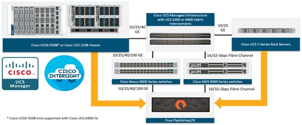
The FlashStack architecture was jointly developed by Cisco and Pure Storage. All FlashStack components are integrated, allowing customers to deploy the solution quickly and economically while eliminating many of the risks associated with researching, designing, building, and deploying similar solutions from the foundation. One of the main benefits of FlashStack is its ability to maintain consistency at scale. Each of the component families shown in Figure 1 (Cisco UCS, Cisco Nexus, Cisco MDS, and Pure Storage FlashArray systems) offers platform and resource options to scale up or scale out the infrastructure while supporting the same features and functions.
Cisco Unified Computing System
Cisco Unified Computing System (Cisco UCS) is a next-generation data center platform that integrates computing, networking, storage access, and virtualization resources into a cohesive system designed to reduce total cost of ownership and increase business agility. The system integrates a low-latency, lossless 10-100 Gigabit Ethernet unified network fabric with enterprise-class, x86-architecture servers. The system is an integrated, scalable, multi-chassis platform with a unified management domain for managing all resources.
Cisco Unified Computing System consists of the following subsystems:
● Compute: The compute piece of the system incorporates servers based on the third-generation Intel Xeon Scalable processors. Servers are available in blade and rack form factor, managed by Cisco UCS Manager.
● Network: The integrated network fabric in the system provides a low-latency, lossless, 10/25/40/100 Gbps Ethernet fabric. Networks for LAN, SAN and management access are consolidated within the fabric. The unified fabric uses the innovative Single Connect technology to lower costs by reducing the number of network adapters, switches, and cables. This in turn lowers the power and cooling needs of the system.
● Virtualization: The system unleashes the full potential of virtualization by enhancing the scalability, performance, and operational control of virtual environments. Cisco security, policy enforcement, and diagnostic features are now extended into virtual environments to support evolving business needs.
● Storage access: Cisco UCS provides consolidated access to both SAN storage and Network Attached Storage over the unified fabric. This provides customers with storage choices and investment protection. Also, the server administrators can pre-assign storage-access policies to storage resources, for simplified storage connectivity and management leading to increased productivity.
● Management: The system uniquely integrates compute, network, and storage access subsystems, enabling it to be managed as a single entity through Cisco UCS Manager software. Cisco UCS Manager increases IT staff productivity by enabling storage, network, and server administrators to collaborate on Service Profiles that define the desired physical configurations and infrastructure policies for applications. Service Profiles increase business agility by enabling IT to automate and provision re-sources in minutes instead of days.
Cisco UCS Differentiators
Cisco Unified Computing System is revolutionizing the way servers are managed in the datacenter. The following are the unique differentiators of Cisco Unified Computing System and Cisco UCS Manager:
● Embedded Management: In Cisco UCS, the servers are managed by the embedded firmware in the Fabric Interconnects, eliminating the need for any external physical or virtual devices to manage the servers.
● Unified Fabric: In Cisco UCS, from blade server chassis or rack servers to FI, there is a single Ethernet cable used for LAN, SAN, and management traffic. This converged I/O results in reduced cables, SFPs and adapters – reducing capital and operational expenses of the overall solution.
● Auto Discovery: By simply inserting the blade server in the chassis or connecting the rack server to the fabric interconnect, discovery and inventory of compute resources occurs automatically without any management intervention. The combination of unified fabric and auto-discovery enables the wire-once architecture of Cisco UCS, where compute capability of Cisco UCS can be extended easily while keeping the existing external connectivity to LAN, SAN, and management networks.
● Policy Based Resource Classification: Once Cisco UCS Manager discovers a compute resource, it can be automatically classified to a given resource pool based on policies defined. This capability is useful in multi-tenant cloud computing. This CVD showcases the policy-based resource classification of Cisco UCS Manager.
● Combined Rack and Blade Server Management: Cisco UCS Manager can manage Cisco UCS B-series blade servers and Cisco UCS C-series rack servers under the same Cisco UCS domain. This feature, along with stateless computing makes compute resources truly hardware form factor agnostic.
● Model based Management Architecture: The Cisco UCS Manager architecture and management database is model based, and data driven. An open XML API is provided to operate on the management model. This enables easy and scalable integration of Cisco UCS Manager with other management systems.
● Policies, Pools, Templates: The management approach in Cisco UCS Manager is based on defining policies, pools, and templates, instead of cluttered configuration, which enables a simple, loosely coupled, data driven approach in managing compute, network, and storage resources.
● Loose Referential Integrity: In Cisco UCS Manager, a service profile, port profile or policies can refer to other policies or logical resources with loose referential integrity. A referred policy cannot exist at the time of authoring the referring policy or a referred policy can be deleted even though other policies are referring to it. This provides different subject matter experts to work independently from each other. This provides great flexibility where different experts from different domains, such as network, storage, security, server, and virtualization work together to accomplish a complex task.
● Policy Resolution: In Cisco UCS Manager, a tree structure of organizational unit hierarchy can be created that mimics the re-al-life tenants and/or organization relationships. Various policies, pools and templates can be defined at different levels of organization hierarchy. A policy referring to another policy by name is resolved in the organizational hierarchy with closest policy match. If no policy with specific name is found in the hierarchy of the root organization, then the special policy named “default” is searched. This policy resolution practice enables automation friendly management APIs and provides great flexibility to owners of different organizations.
● Service Profiles and Stateless Computing: A service profile is a logical representation of a server, carrying its various identities and policies. This logical server can be assigned to any physical compute resource as far as it meets the resource requirements. Stateless computing enables procurement of a server within minutes, which used to take days in legacy server management systems.
● Built-in Multi-Tenancy Support: The combination of policies, pools and templates, loose referential integrity, policy resolution in the organizational hierarchy and a service profiles-based approach to compute resources makes Cisco UCS Manager inherently friendly to multi-tenant environments typically observed in private and public clouds.
● Extended Memory: The enterprise-class Cisco UCS Blade Server extends the capabilities of the Cisco Unified Computing System portfolio in a half-width blade form factor. It harnesses the power of the latest Intel Xeon Scalable Series processor family CPUs and Intel Optane DC Persistent Memory (DCPMM) with up to 18TB of RAM (using 256GB DDR4 DIMMs and 512GB DCPMM).
● Simplified QoS: Even though Fibre Channel and Ethernet are converged in the Cisco UCS fabric, built-in support for QoS and lossless Ethernet makes it seamless. Network Quality of Service (QoS) is simplified in Cisco UCS Manager by representing all system classes in one GUI panel.
Cisco Intersight
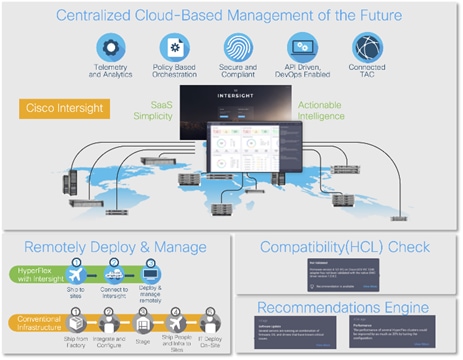
Cisco Intersight is a lifecycle management platform for your infrastructure, regardless of where it resides. In your enterprise data center, at the edge, in remote and branch offices, at retail and industrial sites—all these locations present unique management challenges and have typically required separate tools. Cisco Intersight Software as a Service (SaaS) unifies and simplifies your experience of the Cisco Unified Computing System (Cisco UCS).
Cisco Intersight software delivers a new level of cloud-powered intelligence that supports lifecycle management with continuous improvement. It is tightly integrated with the Cisco Technical Assistance Center (TAC). Expertise and information flow seamlessly between Cisco Intersight and IT teams, providing global management of Cisco infrastructure, anywhere. Remediation and problem resolution are supported with automated upload of error logs for rapid root-cause analysis.
● Automate your infrastructure.
Cisco has a strong track record for management solutions that deliver policy-based automation to daily operations. Intersight SaaS is a natural evolution of our strategies. Cisco designed Cisco UCS to be 100 percent programmable. Cisco Intersight simply moves the control plane from the network into the cloud. Now you can manage your Cisco UCS and infrastructure wherever it resides through a single interface.
● Deploy your way.
If you need to control how your management data is handled, comply with data locality regulations, or consolidate the number of outbound connections from servers, you can use the Cisco Intersight Virtual Appliance for an on-premises experience. Cisco Intersight Virtual Appliance is continuously updated just like the SaaS version, so regardless of which approach you implement, you never have to worry about whether your management software is up to date.
● DevOps ready.
If you are implementing DevOps practices, you can use the Cisco Intersight API with either the cloud-based or virtual appliance offering. Through the API you can configure and manage infrastructure as code—you are not merely configuring an abstraction layer; you are managing the real thing. Through the API and support of cloud-based RESTful API, Terraform providers, Microsoft PowerShell scripts, or Python software, you can automate the deployment of settings and software for both physical and virtual layers. Using the API, you can simplify infrastructure lifecycle operations and increase the speed of continuous application delivery.
● Pervasive simplicity.
Simplify the user experience by managing your infrastructure regardless of where it is installed.
● Actionable intelligence.
● Use best practices to enable faster, proactive IT operations.
● Gain actionable insight for ongoing improvement and problem avoidance.
● Manage anywhere.
● Deploy in the data center and at the edge with massive scale.
● Get visibility into the health and inventory detail for your Intersight Managed environment on-the-go with the Cisco Inter-sight Mobile App.
For more information about Cisco Intersight and the different deployment options, go to: Cisco Intersight – Manage your systems anywhere.
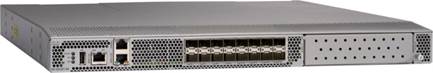
The Cisco UCS Fabric Interconnect (FI) is a core part of the Cisco Unified Computing System, providing both network connectivity and management capabilities for the system. Depending on the model chosen, the Cisco UCS Fabric Interconnect offers line-rate, low-latency, lossless 10 Gigabit, 25 Gigabit, 40 Gigabit, or 100 Gigabit Ethernet, Fibre Channel over Ethernet (FCoE) and Fibre Channel connectivity. Cisco UCS Fabric Interconnects provide the management and communication backbone for the Cisco UCS C-Series, Cisco UCS X-Series, Cisco UCS B-Series Blade Servers, and Cisco UCS Chassis. All servers and chassis, and therefore all Compute Nodes, attached to the Cisco UCS Fabric Interconnects become part of a single, highly available management domain. In addition, by supporting unified fabrics, the Cisco UCS Fabric Interconnects provide both the LAN and SAN connectivity for all servers within its domain.
For networking performance, the Cisco UCS 6536 uses a cut-through architecture, supporting deterministic, low-latency, line-rate 10/25/40/100 Gigabit Ethernet ports, a switching capacity of 7.42 Tbps per FI and 14.84 Tbps per unified fabric domain, independent of packet size and enabled services. It enables 1600Gbps bandwidth per X9508 chassis with X9108-IFM-100G in addition to enabling end-to-end 100G ethernet and 200G aggregate bandwidth per X210c compute node. With the X9108-IFM-25G and the IOM 2408, it enables 400Gbps bandwidth per chassis per FI domain. The product family supports Cisco® low-latency, lossless 10/25/40/100 Gigabit Ethernet unified network fabric capabilities, which increases the reliability, efficiency, and scalability of Ethernet networks. The Cisco UCS 6536 Fabric Interconnect supports multiple traffic classes over a lossless Ethernet fabric from the server through the fabric interconnect. Significant TCO savings come from the Unified Fabric optimized server design in which Network Interface Cards (NICs), Host Bus Adapters (HBAs), cables, and switches can be consolidated.
Cisco UCS 6536 Fabric Interconnect
The Cisco UCS Fabric Interconnects (FIs) provide a single point for connectivity and management for the entire Cisco Unified Computing System. Typically deployed as an active/active pair, the system’s FIs integrate all components into a single, highly available management domain controlled by Cisco Intersight. Cisco UCS FIs provide a single unified fabric for the system, with low-latency, lossless, cut-through switching that supports LAN, SAN, and management traffic using a single set of cables.
![]()
The Cisco UCS 6536 utilized in this design is a 36-port Fabric Interconnect. This single RU device includes up to 36 10/25/40/100 Gbps Ethernet ports, 16 8/16/32-Gbps Fibre Channel ports via 4 128 Gbps to 4x32 Gbps breakouts on ports 33-36. All 36 ports support breakout cables or QSA interfaces.
Cisco UCS X210c M7 Compute Node
The Cisco UCS X9508 Chassis is designed to host up to eight Cisco UCS X210c M7 Compute Nodes. The hardware details of the Cisco UCS X210c M7 Compute Nodes are shown in Figure 4.
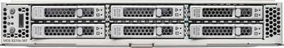
The Cisco UCS X210c M7 features:
● CPU: Up to 2x 4th Gen Intel Xeon Scalable Processors with up to 60 cores per processor and up to 2.625 MB Level 3 cache per core and up to 112.5 MB per CPU.
● Memory: Up to 8TB of main memory with 32x 256 GB DDR5-4800 DIMMs.
● Disk storage: Up to six hot-pluggable, solid-state drives (SSDs), or non-volatile memory express (NVMe) 2.5-inch drives with a choice of enterprise-class redundant array of independent disks (RAIDs) or passthrough controllers, up to two M.2 SATA drives with optional hardware RAID.
● Optional front mezzanine GPU module: The Cisco UCS front mezzanine GPU module is a passive PCIe Gen 4.0 front mezzanine option with support for up to two U.2 NVMe drives and two HHHL GPUs.
● mLOM virtual interface cards:
◦ Cisco UCS Virtual Interface Card (VIC) 15420 occupies the server's modular LAN on motherboard (mLOM) slot, enabling up to 50 Gbps of unified fabric connectivity to each of the chassis intelligent fabric modules (IFMs) for 100 Gbps connectivity per server.
◦ Cisco UCS Virtual Interface Card (VIC) 15231 occupies the server's modular LAN on motherboard (mLOM) slot, enabling up to 100 Gbps of unified fabric connectivity to each of the chassis intelligent fabric modules (IFMs) for 100 Gbps connectivity per server.
● Optional mezzanine card:
◦ Cisco UCS 5th Gen Virtual Interface Card (VIC) 15422 can occupy the server's mezzanine slot at the bottom rear of the chassis. This card's I/O connectors link to Cisco UCS X-Fabric technology. An included bridge card extends this VIC's 2x 50 Gbps of network connections through IFM connectors, bringing the total bandwidth to 100 Gbps per fabric (for a total of 200 Gbps per server).
◦ Cisco UCS PCI Mezz card for X-Fabric can occupy the server's mezzanine slot at the bottom rear of the chassis. This card's I/O connectors link to Cisco UCS X-Fabric modules and enable connectivity to the Cisco UCS X440p PCIe Node.
● All VIC mezzanine cards also provide I/O connections from the Cisco UCS X210c M7 compute node to the X440p PCIe Node.
● Security: The server supports an optional Trusted Platform Module (TPM). Additional security features include a secure boot FPGA and ACT2 anticounterfeit provisions.
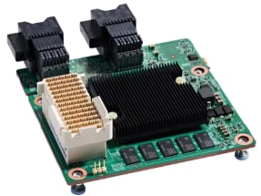
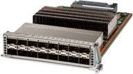
Cisco UCS Virtual Interface Cards (VICs)
The Cisco UCS VIC 15000 series is designed for Cisco UCS X-Series M6/M7 Blade Servers, Cisco UCS B-Series M6 Blade Servers, and Cisco UCS C-Series M6/M7 Rack Servers. The adapters are capable of supporting 10/25/40/50/100/200-Gigabit Ethernet and Fibre Channel over Ethernet (FCoE). They incorporate Cisco’s next-generation Converged Network Adapter (CNA) technology and offer a comprehensive feature set, providing investment protection for future feature software releases
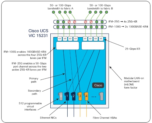
The Cisco UCS VIC 15231 (Figure 5) is a 2x100-Gbps Ethernet/FCoE-capable modular LAN on motherboard (mLOM) designed exclusively for the Cisco UCS X210 Compute Node. The Cisco UCS VIC 15231 enables a policy-based, stateless, agile server infrastructure that can present to the host PCIe standards-compliant interfaces that can be dynamically configured as either NICs or HBAs.
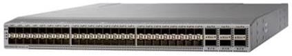
Cisco Nexus 93180YC-FX Switches
The Cisco Nexus 93180YC-EX Switch provides a flexible line-rate Layer 2 and Layer 3 feature set in a compact form factor. Designed with Cisco Cloud Scale technology, it supports highly scalable cloud architectures. With the option to operate in Cisco NX-OS or Application Centric Infrastructure (ACI) mode, it can be deployed across enterprise, service provider, and Web 2.0 data centers.
● Architectural Flexibility
◦ Includes top-of-rack or middle-of-row fiber-based server access connectivity for traditional and leaf-spine architectures.
◦ Leaf node support for Cisco ACI architecture is provided in the roadmap.
◦ Increase scale and simplify management through Cisco Nexus 2000 Fabric Extender support.
● Feature Rich
◦ Enhanced Cisco NX-OS Software is designed for performance, resiliency, scalability, manageability, and programmability.
◦ ACI-ready infrastructure helps you take advantage of automated policy-based systems management.
◦ Virtual Extensible LAN (VXLAN) routing provides network services.
◦ Rich traffic flow telemetry with line-rate data collection.
◦ Real-time buffer utilization per port and per queue, for monitoring traffic micro-bursts and application traffic patterns.
● Highly Available and Efficient Design
◦ High-density, non-blocking architecture.
◦ Easily deployed into either a hot-aisle and cold-aisle configuration.
◦ Redundant, hot-swappable power supplies and fan trays.
● Simplified Operations
◦ Power-On Auto Provisioning (POAP) support allows for simplified software upgrades and configuration file installation.
◦ An intelligent API offers switch management through remote procedure calls (RPCs, JSON, or XML) over a HTTP/HTTPS infra-structure.
◦ Python Scripting for programmatic access to the switch command-line interface (CLI).
◦ Hot and cold patching, and online diagnostics.
● Investment Protection
A Cisco 40 Gbe bidirectional transceiver allows reuse of an existing 10 Gigabit Ethernet multimode cabling plant for 40 Giga-bit Ethernet Support for 1 Gbe and 10 Gbe access connectivity for data centers migrating access switching infrastructure to faster speed. The following is supported:
● 1.8 Tbps of bandwidth in a 1 RU form factor.
● 48 fixed 1/10/25-Gbe SFP+ ports.
● 6 fixed 40/100-Gbe QSFP+ for uplink connectivity.
● Latency of less than 2 microseconds.
● Front-to-back or back-to-front airflow configurations.
● 1+1 redundant hot-swappable 80 Plus Platinum-certified power supplies.
● Hot swappable 3+1 redundant fan trays.
Cisco MDS 9132T 32-Gb Fiber Channel Switch
The next-generation Cisco MDS 9132T 32-Gb 32-Port Fibre Channel Switch (Figure 8) provides high-speed Fibre Channel connectivity from the server rack to the SAN core. It empowers small, midsize, and large enterprises that are rapidly deploying cloud-scale applications using extremely dense virtualized servers, providing the dual benefits of greater bandwidth and consolidation.
Small-scale SAN architectures can be built from the foundation using this low-cost, low-power, non-blocking, line-rate, and low-latency, bi-directional airflow capable, fixed standalone SAN switch connecting both storage and host ports.
Medium-size to large-scale SAN architectures built with SAN core directors can expand 32-Gb connectivity to the server rack using these switches either in switch mode or Network Port Virtualization (NPV) mode.
Additionally, investing in this switch for the lower-speed (4- or 8- or 16-Gb) server rack gives you the option to upgrade to 32-Gb server connectivity in the future using the 32-Gb Host Bus Adapter (HBA) that are available today. The Cisco MDS 9132T 32-Gb 32-Port Fibre Channel switch also provides unmatched flexibility through a unique port expansion module (Figure 8) that provides a robust cost-effective, field swappable, port upgrade option.
This switch also offers state-of-the-art SAN analytics and telemetry capabilities that have been built into this next-generation hardware platform. This new state-of-the-art technology couples the next-generation port ASIC with a fully dedicated Network Processing Unit designed to complete analytics calculations in real time. The telemetry data extracted from the inspection of the frame headers are calculated on board (within the switch) and, using an industry-leading open format, can be streamed to any analytics-visualization platform. This switch also includes a dedicated 10/100/1000BASE-T telemetry port to maximize data delivery to any telemetry receiver including Cisco Data Center Network Manager.
● Features
◦ High performance: Cisco MDS 9132T architecture, with chip-integrated nonblocking arbitration, provides consistent 32-Gb low-latency performance across all traffic conditions for every Fibre Channel port on the switch.
◦ Capital Expenditure (CapEx) savings: The 32-Gb ports allow you to deploy them on existing 16- or 8-Gb transceivers, reducing initial CapEx with an option to upgrade to 32-Gb transceivers and adapters in the future.
◦ High availability: Cisco MDS 9132T switches continue to provide the same outstanding availability and reliability as the previous-generation Cisco MDS 9000 Family switches by providing optional redundancy on all major components such as the power supply and fan. Dual power supplies also facilitate redundant power grids.
◦ Pay-as-you-grow: The Cisco MDS 9132T Fibre Channel switch provides an option to deploy as few as eight 32-Gb Fibre Channel ports in the entry-level variant, which can grow by 8 ports to 16 ports, and thereafter with a port expansion module with sixteen 32-Gb ports, to up to 32 ports. This approach results in lower initial investment and power consumption for entry-level configurations of up to 16 ports compared to a fully loaded switch. Upgrading through an expansion module also reduces the overhead of managing multiple instances of port activation licenses on the switch. This unique combination of port upgrade options allow four possible configurations of 8 ports, 16 ports, 24 ports and 32 ports.
◦ Next-generation Application-Specific Integrated Circuit (ASIC): The Cisco MDS 9132T Fibre Channel switch is powered by the same high-performance 32-Gb Cisco ASIC with an integrated network processor that powers the Cisco MDS 9700 48-Port 32-Gb Fibre Channel Switching Module. Among all the advanced features that this ASIC enables, one of the most notable is inspection of Fibre Channel and Small Computer System Interface (SCSI) headers at wire speed on every flow in the smallest form-factor Fibre Channel switch without the need for any external taps or appliances. The recorded flows can be analyzed on the switch and also exported using a dedicated 10/100/1000BASE-T port for telemetry and analytics purposes.
◦ Intelligent network services: Slow-drain detection and isolation, VSAN technology, Access Control Lists (ACLs) for hardware-based intelligent frame processing, smartzoning and fabric wide Quality of Service (QoS) enable migration from SAN islands to enterprise-wide storage networks. Traffic encryption is optionally available to meet stringent security requirements.
◦ Sophisticated diagnostics: The Cisco MDS 9132T provides intelligent diagnostics tools such as Inter-Switch Link (ISL) diagnostics, read diagnostic parameters, protocol decoding, network analysis tools, and integrated Cisco Call Home capability for greater reliability, faster problem resolution, and reduced service costs.
◦ Virtual machine awareness: The Cisco MDS 9132T provides visibility into all virtual machines logged into the fabric. This feature is available through HBAs capable of priority tagging the Virtual Machine Identifier (VMID) on every FC frame. Virtual machine awareness can be extended to intelligent fabric services such as analytics[1] to visualize performance of every flow originating from each virtual machine in the fabric.
◦ Programmable fabric: The Cisco MDS 9132T provides powerful Representational State Transfer (REST) and Cisco NX-API capabilities to enable flexible and rapid programming of utilities for the SAN as well as polling point-in-time telemetry data from any external tool.
◦ Single-pane management: The Cisco MDS 9132T can be provisioned, managed, monitored, and troubleshot using Cisco Data Center Network Manager (DCNM), which currently manages the entire suite of Cisco data center products.
◦ Self-contained advanced anticounterfeiting technology: The Cisco MDS 9132T uses on-board hardware that protects the entire system from malicious attacks by securing access to critical components such as the bootloader, system image loader and Joint Test Action Group (JTAG) interface.
Citrix Virtual Apps and Desktops
When you want to keep workloads on premises, Citrix Virtual Apps and Desktops is the way to go. Whether you’re a corporate security team facing strict compliance standards or need to stay in the datacenter for operational reasons, Citrix makes it easy to deliver IT-managed VDI. It’s app and desktop virtualization, done your way. With a wide range of features to boost productivity and increase security.
For more information, go to: Citrix Virtual Apps and Desktops.
Citrix Virtual Apps and Desktops RDS Sessions and Windows 11 Desktops
The virtual app and desktop solution is designed for an exceptional experience.
Today's employees spend more time than ever working remotely, causing companies to rethink how IT services should be delivered. To modernize infrastructure and maximize efficiency, many are turning to desktop as a service (DaaS) to enhance their physical desktop strategy, or they are updating on-premises virtual desktop infrastructure (VDI) deployments. Managed in the cloud, these deployments are high-performance virtual instances of desktops and apps that can be delivered from any datacenter or public cloud provider.
DaaS and VDI capabilities provide corporate data protection as well as an easily accessible hybrid work solution for employees. Because all data is stored securely in the cloud or datacenter, rather than on devices, end-users can work securely from anywhere, on any device, and over any network—all with a fully IT-provided experience. IT also gains the benefit of centralized management, so they can scale their environments quickly and easily. By separating endpoints and corporate data, resources stay protected even if the devices are compromised.
As a leading VDI and DaaS provider, Citrix provides the capabilities organizations need for deploying virtual apps and desktops to reduce downtime, increase security, and alleviate the many challenges associated with traditional desktop management.
For more information, go to:
https://docs.citrix.com/en-us/citrix-virtual-apps-desktops
Citrix Virtual Apps and Desktops Design Fundamentals
An ever growing and diverse base of user devices, complexity in management of traditional desktops, security, and even Bring Your Own (BYO) device to work programs are prime reasons for moving to a virtual desktop solution.
Citrix Virtual Apps and Desktops 7 integrates Hosted Shared and VDI desktop virtualization technologies into a unified architecture that enables a scalable, simple, efficient, and manageable solution for delivering Windows applications and desktops as a service.
You can select applications from an easy-to-use “store” that is accessible from tablets, smartphones, PCs, Macs, and thin clients. Virtual Apps and Desktops delivers a native touch-optimized experience with HDX high-definition performance, even over mobile networks.
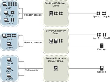
Collections of identical virtual machines or physical computers are managed as a single entity called a Machine Catalog. In this CVD, virtual machine provisioning relies on Citrix Provisioning Services and Machine Creation Services to make sure that the machines in the catalog are consistent. In this CVD, machines in the Machine Catalog are configured to run either a Multi-session OS VDA (Windows Server OS) or a Single-session OS VDA (Windows Desktop OS).
To deliver desktops and applications to users, you create a Machine Catalog and then allocate machines from the catalog to users by creating Delivery Groups. Delivery Groups provide desktops, applications, or a combination of desktops and applications to users. Creating a Delivery Group is a flexible way of allocating machines and applications to users. In a Delivery Group, you can:
● Use machines from multiple catalogs
● Allocate a user to multiple machines
● Allocate multiple users to one machine
As part of the creation process, you specify the following Delivery Group properties:
● Users, groups, and applications allocated to Delivery Groups
● Desktop settings to match users' needs
● Desktop power management options
Figure 10 illustrates how users access desktops and applications through machine catalogs and delivery groups.
Citrix Virtual Apps and Desktops 7 can be deployed with or without Citrix Provisioning Services (PVS). The advantage of using Citrix PVS is that it allows virtual machines to be provisioned and re-provisioned in real-time from a single shared-disk image. In this way administrators can completely eliminate the need to manage and patch individual systems and reduce the number of disk images that they manage, even as the number of machines continues to grow, simultaneously providing the efficiencies of a centralized management with the benefits of distributed processing.
The Provisioning Services solution’s infrastructure is based on software-streaming technology. After installing and configuring Provisioning Services components, a single shared disk image (vDisk) is created from a device’s hard drive by taking a snapshot of the OS and application image, and then storing that image as a vDisk file on the network. A device that is used during the vDisk creation process is the Master target device. Devices or virtual machines that use the created vDisks are called target devices.
When a target device is turned on, it is set to boot from the network and to communicate with a Provisioning Server. Unlike thin-client technology, processing takes place on the target device.
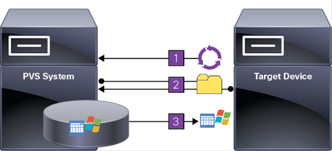
The target device downloads the boot file from a Provisioning Server (Step 2) and boots. Based on the boot configuration settings, the appropriate vDisk is mounted on the Provisioning Server (Step 3). The vDisk software is then streamed to the target device as needed, appearing as a regular hard drive to the system.
Instead of immediately pulling all the vDisk contents down to the target device (as with traditional imaging solutions), the data is brought across the network in real-time as needed. This approach allows a target device to get a completely new operating system and set of software in the time it takes to reboot. This approach dramatically decreases the amount of network bandwidth required and making it possible to support a larger number of target devices on a network without impacting performance
Citrix PVS can create desktops as Pooled or Private:
● Pooled Desktop: A pooled virtual desktop uses Citrix PVS to stream a standard desktop image to multiple desktop instances upon boot.
● Private Desktop: A private desktop is a single desktop assigned to one distinct user.
● The alternative to Citrix Provisioning Services for pooled desktop deployments is Citrix Machine Creation Services (MCS), which is integrated with the Virtual Apps and Desktops Studio console.
Locate the PVS Write Cache
When considering a PVS deployment, there are some design decisions that need to be made regarding the write cache for the target devices that leverage provisioning services. The write cache is a cache of all data that the target device has written. If data is written to the PVS vDisk in a caching mode, the data is not written back to the base vDisk. Instead, it is written to a write cache file in one of the following locations:
● Cache in device RAM. Write cache can exist as a temporary file in the target device’s RAM. This provides the fastest method of disk access since memory access is always faster than disk access.
● Cache in device RAM with overflow on hard disk. This method uses VHDX differencing format and is only available for Windows 11 and Server 2008 R2 and later. When RAM is zero, the target device write cache is only written to the local disk. When RAM is not zero, the target device write cache is written to RAM first. When RAM is full, the least recently used block of data is written to the local differencing disk to accommodate newer data on RAM. The amount of RAM specified is the non-paged kernel memory that the target device will consume.
● Cache on a server. Write cache can exist as a temporary file on a Provisioning Server. In this configuration, all writes are handled by the Provisioning Server, which can increase disk I/O and network traffic. For additional security, the Provisioning Server can be configured to encrypt write cache files. Since the write-cache file persists on the hard drive between reboots, encrypted data provides data protection in the event a hard drive is stolen.
● Cache on server persisted. This cache option allows for the saved changes between reboots. Using this option, a rebooted target device is able to retrieve changes made from previous sessions that differ from the read only vDisk image. If a vDisk is set to this method of caching, each target device that accesses the vDisk automatically has a device-specific, writable disk file created. Any changes made to the vDisk image are written to that file, which is not automatically deleted upon shutdown.
Note: In this CVD, Provisioning Server 2022 was used to manage Pooled/Non-Persistent Single-session OS Machines with “Cache in device RAM with Overflow on Hard Disk” for each virtual machine. This design enables good scalability to many thousands of desktops. Provisioning Server 2022 was used for Active Directory machine account creation and management as well as for streaming the shared disk to the hypervisor hosts.
Example Citrix Virtual Apps and Desktops Deployments
Two examples of typical Virtual Apps and Desktops deployments are as follows:
● A distributed components configuration
● A multiple site configuration
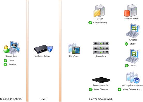
Distributed Components Configuration
You can distribute the components of your deployment among a greater number of servers or provide greater scalability and failover by increasing the number of controllers in your site. You can install management consoles on separate computers to manage the deployment remotely. A distributed deployment is necessary for an infrastructure based on remote access through NetScaler Gateway (formerly called Access Gateway).
Figure 12 shows an example of a distributed components configuration. A simplified version of this configuration is often deployed for an initial proof-of-concept (POC) deployment. The CVD described in this document deploys Citrix Virtual Apps and Desktops in a configuration that resembles this distributed component configuration shown.
If you have multiple regional sites, you can use Citrix NetScaler to direct user connections to the most appropriate site and StoreFront to deliver desktops and applications to users.
Figure 13 depicts multiple sites; a site was created in two data centers. Having two sites globally, rather than just one, minimizes the amount of unnecessary WAN traffic.
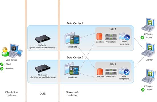
You can use StoreFront to aggregate resources from multiple sites to provide users with a single point of access with NetScaler. A separate Studio console is required to manage each site; sites cannot be managed as a single entity. You can use Director to support users across sites.
Citrix NetScaler accelerates application performance, load balances servers, increases security, and optimizes the user experience. In this example, two NetScalers are used to provide a high availability configuration. The NetScalers are configured for Global Server Load Balancing and positioned in the DMZ to provide a multi-site, fault-tolerant solution.
Note: The CVD was done based on single site and did not use NetScaler for its infrastructure and testing.
Easily deliver the Citrix portfolio of products as a service. Citrix Cloud services simplify the delivery and management of Citrix technologies extending existing on-premises software deployments and creating hybrid workspace services.
● Fast: Deploy apps and desktops, or complete secure digital workspaces in hours, not weeks.
● Adaptable: Choose to deploy on any cloud or virtual infrastructure — or a hybrid of both.
● Secure: Keep all proprietary information for your apps, desktops, and data under your control.
● Simple: Implement a fully-integrated Citrix portfolio through a single-management plane to simplify administration
Design a Virtual Apps and Desktops Environment for Different Workloads
With Citrix Virtual Apps and Desktops, the method you choose to provide applications or desktops to users depends on the types of applications and desktops you are hosting and available system resources, as well as the types of users and user experience you want to provide.
| Desktop Type |
User Experience |
| Server OS machines |
You want: Inexpensive server-based delivery to minimize the cost of delivering applications to a large number of users, while providing a secure, high-definition user experience. Your users: Perform well-defined tasks and do not require personalization or offline access to applications. Users may include task workers such as call center operators and retail workers, or users that share workstations. Application types: Any application. |
| Desktop OS machines |
You want: A client-based application delivery solution that is secure, provides centralized management, and supports a large number of users per host server (or hypervisor), while providing users with applications that display seamlessly in high-definition. Your users: Are internal, external contractors, third-party collaborators, and other provisional team members. Users do not require off-line access to hosted applications. Application types: Applications that might not work well with other applications or might interact with the operating system, such as .NET framework. These types of applications are ideal for hosting on virtual machines. Applications running on older operating systems such as Windows XP or Windows Vista, and older architectures, such as 32-bit or 16-bit. By isolating each application on its own virtual machine, if one machine fails, it does not impact other users. |
| Remote PC Access |
You want: Employees with secure remote access to a physical computer without using a VPN. For example, the user may be accessing their physical desktop PC from home or through a public WIFI hotspot. Depending upon the location, you may want to restrict the ability to print or copy and paste outside of the desktop. This method enables BYO device support without migrating desktop images into the data center. Your users: Employees or contractors that have the option to work from home but need access to specific software or data on their corporate desktops to perform their jobs remotely. Host: The same as Desktop OS machines. Application types: Applications that are delivered from an office computer and display seamlessly in high definition on the remote user's device. |
For this Cisco Validated Design, the following designs are included:
● Single-session OS Solution:
◦ MCS: 2000 Windows 11 Virtual desktops random pooled will be configured and tested
◦ PVS: 2000 Windows 11 Virtual desktops random pooled will be configured and tested
● Multi-session OS Solution:
◦ RDS: 2500 Windows Server 2022 random pooled desktops will be configured and tested
VMware vSphere is an enterprise workload platform for holistically managing large collections of infrastructures (resources including CPUs, storage, and networking) as a seamless, versatile, and dynamic operating environment. Unlike traditional operating systems that manage an individual machine, VMware vSphere aggregates the infrastructure of an entire data center to create a single powerhouse with resources that can be allocated quickly and dynamically to any application in need.
The VMware vSphere 8 Update 2 release delivered enhanced value in operational efficiency for admins, supercharged performance for higher-end AI/ML workloads, and elevated security across the environment. VMware vSphere 8 Update 2 has now achieved general availability.
For more information about the VMware vSphere 8 Update 2 three key areas of enhancements, see: VMware blog.
VMware vSphere vCenter
VMware vCenter Server provides unified management of all hosts and VMs from a single console and aggregates performance monitoring of clusters, hosts, and VMs. VMware vCenter Server gives administrators a deep insight into the status and configuration of compute clusters, hosts, VMs, storage, the guest OS, and other critical components of a virtual infrastructure. VMware vCenter manages the rich set of features available in a VMware vSphere environment.
Ansible is simple and powerful, allowing you to easily manage various physical devices within FlashStack including the provisioning of Cisco UCS servers, Cisco Nexus switches, Pure Storage FlashArray storage and VMware vSphere. Using Ansible’s Playbook-based automation is easy and integrates into your current provisioning infrastructure.
Cisco Intersight Assist Device Connector for VMware vCenter and Pure Storage FlashArray
Cisco Intersight integrates with VMware vCenter and Pure Storage FlashArray as follows:
● Cisco Intersight uses the device connector running within Cisco Intersight Assist virtual appliance to communicate with the VMware vCenter.
● Cisco Intersight uses the device connector running within a Cisco Intersight Assist virtual appliance to integrate with all Pure Storage FlashArray models. The newest version 1.3 of Pure Storage integration to Cisco Intersight supports REST API 2.x for FlashArray products (running Purity//FA 6.0.3 or later), along with User Agent support (for telemetry). Intersight Cloud Orchestrator now has new storage tasks for adding/removing/modifying Storage Host and adding/removing a Pure Storage to/from Storage Host.
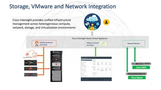
The device connector provides a safe way for connected targets to send information and receive control instructions from the Cisco Intersight portal using a secure Internet connection. The integration brings the full value and simplicity of Cisco Intersight infrastructure management service to VMware hypervisor and FlashArray storage environments. The integration architecture enables FlashStack customers to use new management capabilities with no compromise in their existing VMware or Pure Storage FlashArray operations. IT users will be able to manage heterogeneous infrastructure from a centralized Cisco Intersight portal. At the same time, the IT staff can continue to use VMware vCenter and the Pure Storage dashboard for comprehensive analysis, diagnostics, and reporting of virtual and storage environments. The next section addresses the functions that this integration provides.
Pure Storage FlashArray with Purity//FA for Unified Block and File Storage
Meet today’s data demands with efficient, available, and secure storage. Purity provides unmatched data reduction, 99.9999% availability, always-on encryption, and non-disruptive upgrades.
Consolidated Workloads and Aggregated Data
With Purity, you can easily consolidate workloads and aggregate data with block access over Fibre Channel, iSCSI, NVMe over Fabrics (NVMe/FC, NVMe/RoCE, NVMe/TCP), plus native file access for SMB and NFS.
Unified Block and File Workloads
Block and file protocols run side-by-side in Purity, so you can share your storage for both block-based databases for file-based home directories, file shares, and other file storage. With Purity’s unified block and file support, you avoid the trouble and expense of running multiple incompatible platforms.
Faster, More Consistent Performance
Pure's 100% NVMe storage has built-in QoS that ensures every workload gets the IOPs and throughput it requires. Pure DirectFlash® Fabric gives you maximum throughput for high-performance business applications with microsecond latency that’s far more predictable than with conventional SSDs.
Edge to Core to Cloud Data Access
Authorized users can access their data wherever they are in the world and wherever their data resides—at core data centers on-premises, remote within branch offices, or in the cloud with native data mobility.
Gain confidence knowing that your data is highly available and secure. And when your business grows and evolves, know that your storage can be upgraded with zero disruption.
Storage efficiency to reduce your data center costs. High availability to reduce your risk of downtime. Reduce power to meet corporate green standards. Quality of service to ensure apps stay responsive. Purity provides that and more.
Up to 10:1 Data Reduction
Purity delivers the industry’s most granular and complete data reduction for unmatched storage efficiency. Only unique blocks of data are saved on flash, which removes duplicates that fixed-block architectures often miss. And repetitive binary patterns are removed before data is deduplicated and compressed, streamlining the data reduction process.
| Environment |
Data Reduction |
|
| Virtual Desktop |
5-10:1 |
Virtual desktops (both persistent and non-persistent) are one of the most reducible workloads in the data center. |
| Virtual Server |
4-6:1 |
VMware or Hyper-V, consolidated virtual server environments with mixed applications. |
| Database |
2-4:1 |
OLTP or OLAP, even databases get surprising amounts of data reduction, most of it via compression. |
Always-on Encryption
Purity’s “encrypt everything” approach provides built-in, enterprise-grade data security without user intervention or key management. Maintain regulatory compliance and help achieve GDPR compliance with FIPS 140-2 validated encryption, and impact-free, AES-256 data-at-rest encryption.
High Availability
Purity ensures business continuity by reducing your risk of downtime while keeping mission-critical applications and data online and accessible. Designed from the ground up for flash, Purity RAID-HA protects against concurrent dual-drive failures, initiates re-builds automatically within minutes, and detects and heals bit-errors. Purity also treats performance variability as a failure and uses parity to work around bottlenecks to deliver consistent latency.
Non-disruptive Everything
Downtime isn’t an option when your storage array hosts hundreds of applications. With Purity, you can expand flash capacity, upgrade controllers, replace failed components, and upgrade Purity software itself—all without taking the storage offline or impacting application performance. It’s truly non-disruptive.
Intelligent Quality of Service
Purity continuously tunes infrastructure using always-on quality of service (QoS) to prevent workloads from hogging resources. Without placing artificial limits on workloads, you get full performance for all your workloads and can maximize utilization of the array.
Always-on Protection and Recovery
Secure by default protection and integrated disaster recovery helps keep your business running without disruption. Integrated Pure Storage ActiveDR™ and ActiveCluster™ provide rock-solid business continuity. And for ransomware, Auto-on SafeMode™ adds always-on, out-of-the-box protection without the need to change your setup, environment, or process.
Effortless Data Access
Leverage predictable, high speed data access for all your enterprise apps and web scale workloads. End-to-end NVMe-optimized for flash. Multi-protocol support for FC and Ethernet. Built-in QoS for balanced resource distribution.
| Model |
Capacity |
Physical |
| //X90 |
Up to 3.3 PB / 2.9 PiB effective capacity Up to 915 TB / 832.1 TiB raw capacity |
3-6U 1191-1530 watts (nominal-peak) 200-240 volts (input voltage range) 97 lbs. (44 kg) 5.12” x 18.94” x 29.72” *** |
| //X70 |
Up to 2.4 PB / 2.2 PiB effective capacity Up to 658 TB / 599.2 TiB raw capacity |
3U 1068-1424 watts (nominal-peak) 200-240 volts (input voltage range) 97 lbs. (44 kg) 5.12” x 18.94” x 29.72” chassis |
| //X50 |
Up to 663 TB / 602.9 TiB effect-6ive capacity Up to 185 TB / 171 TiB raw capacity |
3U 1016-1276 watts (nominal-peak) 200-240 volts (input voltage range) 95 lbs. (43.1 kg) 5.12” x 18.94” x 29.72” chassis |
| //X20 |
Up to 314 TB / 285.4 TiB effective capacity Up to 94 TB / 88 TiB raw capacity |
3U 945-1196 watts (nominal-peak) 200-240 volts (input voltage range) 95 lbs. (43.1 kg) 5.12” x 18.94” x 29.72” chassis |
| //X DirectFlash Shelf |
Up to 1.9 PB effective capacity Up to 512 TB / 448.2 TiB raw capacity
|
3U 480-500 watts (nominal-peak) 200-240 volts (input voltage range) 87.7 lbs. (39.8 kg) fully loaded 5.12” x 18.94” x 29.72” chassis |
| Onboard Ports (Per Controller) |
Host I/O Cards (3 Slots/Controller) |
|
| 2 x 1/10/25Gb Ethernet / Replication 2 x 1Gb Management Ports 2 x 100GbE Direct Flash Shelf
|
2-port 10GBase-T Ethernet 2-port 10/25Gb Ethernet, NVMe/Roce, NVMe/TCP 2-port 100Gb Ethernet, NVMe/Roce, NVMe/TCP 4-Port 10/25G Ethernet, NVMe/TCP |
2-port 40/100Gb NVMe/RoCE, NVMe/TCP 2-port 16/32Gb FCP, NVMe/FC (X20 and X50 Models) 4-port 16/32Gb FCP, NVMe/FC (X20 and X50 Models) 2-port 32Gb FCP, 64G capable, NVMe/FC (X70 and X90 Models) 4-port 32Gb FCP, 64G capable, NVMe/FC (X70 and X90 Models) |
* Effective capacity assumes HA, RAID, and metadata overhead, GB-to-GiB conversion, and includes the benefit of data reduction with always-on inline deduplication, compression, and pattern removal. Average data reduction is calculated at 5-to-1 and does not include thin provisioning.
** Calculated using raw label capacity.
*** Some maximum capacity configurations may use Pure Storage DirectFlash Shelf or Pure Expansion Shelf.
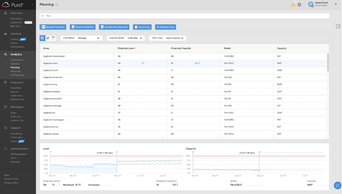
Pure1®, the cloud-based as-a-service data-management platform from Pure Storage®, raises the bar on what you can expect. Pure1 delivers a single AI-driven hub that’s automated with the Pure1 Meta® virtual assistant. You can accomplish common and complex data-management tasks with ease. It’s simple to purchase new or additional services from the service catalog. With Pure1, you can expand anytime, identify problems before they happen, and effortlessly plan for the future.
Optimize
Simplifying complicated processes is a goal for any organization. Reporting and analytics have always seemed to plague traditional data platforms.
That’s no longer the case, thanks to Pure1. Our design goal was straightforward: Create a cloud-based storage management tool that’s simple and easy to use without sacrificing enterprise features.
With Pure1, you can deliver IT outcomes in seconds vs. hours or days. You can eliminate costly downtime by leveraging predictive analytics and respond to dynamic changes quickly by accessing Pure1 from anywhere in the world.
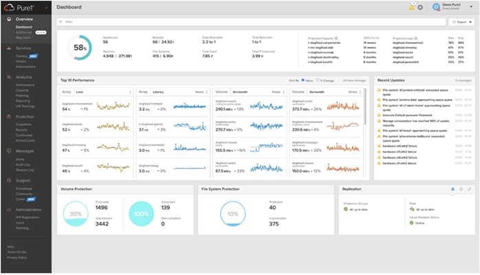
Centralized Setup and Monitoring: Setting up Pure1 is easy: Login to the Pure1 portal, and the software does the rest. As soon as your system is online, Pure1 Meta is hard at work gathering analytics. Live monitoring is available within minutes and accessible from anywhere in the world.
Full-stack Analysis: Access critical information about the health and functioning of your entire stack, including predictive fault analysis, and alerting.
You also get auditing for ransomware protection. Auditing functionality helps you investigate your environment for vulnerabilities.
Reporting: Pure1 has an intuitive, built-in reporting engine that you can use to generate shareable reports on commonly requested information such as capacity, performance, or even service subscription status.
Streamline
Elevate your data services experience with Pure1’s built-in AIOps powered by Pure1 Meta. This industry-leading, AI-driven platform for predictive service management ensures a higher level of data availability and performance. You can see all your data service platforms, whether on-premises FlashArray, Pure Cloud Block Store in Azure or Amazon Web Services, or the Portworx® container storage platform from one place.
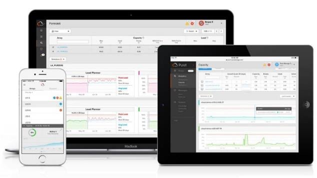
Intelligent Monitoring and Management: Manage your entire fleet of Pure arrays from any device, with just a web browser or the Pure1 mobile application. Pure1 leverages AI to deliver industry-first capabilities that dramatically simplify management and planning. With Pure1, there simply won’t be much for you to do. If something does require attention, the Pure1 mobile app will let you know.
Insight Delivery with Pure1 Workload Planner: With Workload Planner, you can use AI to understand your environment better and identify optimization opportunities. Pure1 can predict array capacity and performance as well as model existing and new workloads. Workload Planner is pre-loaded with 10 common application profiles to help you plan as you bring new applications online. It also contains a “custom” option for application profiles not covered by the built-in options. Workload Planner can easily model these changes to give you a preview of how these changes will affect your overall environment. It can then make upgrade recommendations if your current environment can’t accommodate them. Workload Planner can also:
● Illustrate the effect of potential capacity or performance upgrades on all workloads in your environment as well as new workloads.
● Show the performance and capacity over time of scaling or deleting workloads.
● Model the effect of migrating a workload to another array in your fleet.
● Show the effect of scaling, cloning, or migrating a workload within your environment.
Predictive Fault Analysis and Resolution: The Service Assistant’s AI engine uses analytics from across Pure’s worldwide installed base and alliance ecosystem to quickly pinpoint potential challenges, including hardware degradation, software faults, and environmental issues. Once identified, the Service Assistant generates alerts that include steps to take to resolve the issue. Combined, this allows our teams to proactively resolve more than 70% of cases, preventing downtime. This highly extensible engine also monitors for unusual behavior that may be a sign of ransomware, enabling the Service Assistant to help thwart cyberattacks.
Infrastructure Optimization: The Service Assistant regularly checks the Pure1 cloud to determine if the storage infrastructure is running the latest software version. If it is not, it generates alerts to inform the IT team of upgrades to improve operating performance, add new features, and increase reliability. This feature is designed to investigate all Pure portfolio components and is extensible to other alliance offerings. You can expect this feature to expand to support end-to-end infrastructure.
Analyze
Full-stack analytics (VMA) extends beyond storage,andPure1 has long featured deep analytics on your storage infrastructure.Pure1 now extends that visibility up the stack to give you deep performance metrics on volumes and VMs in your VMware environments, enabling fast and efficient troubleshooting with visibility throughout the stack. You now have insight into latency, bandwidth, and IOPs of your workflows—and the data point you need to resolve issues quickly and pinpoint latency problems or other bottlenecks.
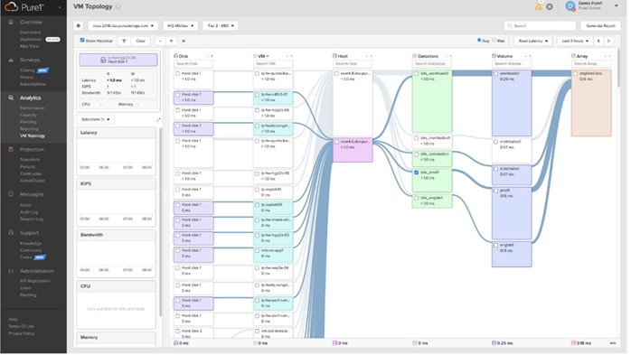
With support for VMFS, vVols, NFS, and vSAN, you get comprehensive analytics and visibility into your virtual environments. VMA reports can help you analyze your environments by providing the following information:
● Top 10 VMs by CPU usage
● Top 10 hosts by CPU usage
● Top 10 hosts by memory usage
● Top 10 datastores by capacity
Empower
Join the next revolution in IT resource purchasing. At Pure, we continue to eliminate archaic IT practices. First was spinning disk and price gouging on data services software and controller upgrades. Then it was utility consumption by eliminating complicated leases in favor of true utility pricing. Now, Pure is taking the IT industry by storm again with the first storage marketplace.
Pure1 Digital Marketplace: Remove the pain and complexity from IT purchasing by giving users full access to the entire Pure catalog of services from a single interface. Buy new systems and services—including FlashArray™, FlashBlade®, FlashStack®, Portworx®, and Pure Cloud Block Store™—as well as Pure Professional Services from an online interface whenever you choose. Expand your as-a-service footprint and add new data services on-demand with the same interface. And when you’re ready, you can order quotes and track new system additions from the comfort of your home.
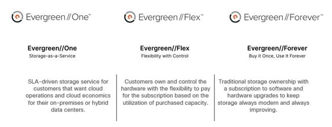
Evergreen™ Subscriptions: The industry’s only true storage-as-a-service platform that unifies on-premises, Amazon Web Services, and Microsoft Azure cloud storage resources into a single data services subscription, delivering an authentic hybrid cloud experience. The cloud pay-as-you-grow model means it’s easy to get in, easy to ramp up, and even easy to get out.
Focused on Customer Satisfaction
Pure’s industry-leading customer satisfaction is driven by continuous, proactive support at every stage, and our driving philosophy is always to do what is right for the customer. Whatever the situation may be, we focus on delivering a solution to free you to focus on growing your business. What’s the best gauge of our customer happiness? A Satmetrix-validated NPS score of 83.5, which puts us in the top 1% of all businesses.
Pure1 Support has been a core factor in Pure delivering proven 99.9999% availability for FlashArray, including maintenance and generational upgrades. Continuous monitoring, predictive analytics, and proactive responses have all played an essential role in keeping our customers' data online and productive.
Management with SaaS Simplicity: Whether managing locally or from the cloud, with Pure1 there’s never any software to install, upgrade, or manage and no need for an extra server. Pure1’s cloud-based model is like SaaS, so our continuous improvements are available to you instantly.
Environment Monitoring: With Pure’s Proactive support, our team becomes your team. Our experts keep tabs on your arrays at all times, helping you through upgrades, responding in minutes for any severity-1 incident, and are ready to notify you if we need your assistance. If you do call us, we'll be standing by with instant access to level-2 support. Our goal is to resolve issues and maintain availability while providing an unmatched, global support experience that is 100% Pure.
Proactive Issue Resolution: Predictive support means you'll be delighted when we find and fix issues you didn't even know existed. Pure1 Meta has big data predictive analytics and machine learning built around our array telemetry to identify and resolve issues before they affect you. Pure arrays send logs home every30 seconds, which Pure1 Meta compares against a growing issue fingerprint library. If it finds any matches, Pure1 opens incidents automatically and notifies support staff of a potential customer issue.
This chapter contains the following:
● Design Considerations for Desktop Virtualization
● Understanding Applications and Data
● Project Planning and Solution Sizing Sample Questions
Design Considerations for Desktop Virtualization
There are many reasons to consider a virtual desktop solution such as an ever growing and diverse base of user devices, complexity in management of traditional desktops, security, and even Bring Your Own Device (BYOD) to work programs. The first step in designing a virtual desktop solution is to understand the user community and the type of tasks that are required to successfully execute their role. The following user classifications are provided:
● Knowledge Workers today do not just work in their offices all day – they attend meetings, visit branch offices, work from home, and even coffee shops. These anywhere workers expect access to all of their same applications and data wherever they are.
● External Contractors are increasingly part of your everyday business. They need access to certain portions of your applications and data, yet administrators still have little control over the devices they use and the locations they work from. Consequently, IT is stuck making trade-offs on the cost of providing these workers a device vs. the security risk of allowing them access from their own devices.
● Task Workers perform a set of well-defined tasks. These workers access a small set of applications and have limited requirements from their PCs. However, since these workers are interacting with your customers, partners, and employees, they have access to your most critical data.
● Mobile Workers need access to their virtual desktop from everywhere, regardless of their ability to connect to a network. In addition, these workers expect the ability to personalize their PCs, by installing their own applications and storing their own data, such as photos and music, on these devices.
● Shared Workstation users are often found in state-of-the-art university and business computer labs, conference rooms or training centers. Shared workstation environments have the constant requirement to re-provision desktops with the latest operating systems and applications as the needs of the organization change, tops the list.
After the user classifications have been identified and the business requirements for each user classification have been defined, it becomes essential to evaluate the types of virtual desktops that are needed based on user requirements. There are essentially five potential desktops environments for each user:
● Traditional PC: A traditional PC is what typically constitutes a desktop environment: physical device with a locally installed operating system.
● Remoted Desktop Server Hosted Sessions: A hosted; server-based desktop is a desktop where the user interacts through a delivery protocol. With hosted, server-based desktops, a single installed instance of a server operating system, such as Microsoft Windows Server 2022, is shared by multiple users simultaneously. Each user receives a desktop "session" and works in an isolated memory space. Remoted Desktop Server Hosted Server sessions: A hosted virtual desktop is a virtual desktop running on a virtualization layer (ESX). The user does not work with and sit in front of the desktop, but instead the user interacts through a delivery protocol.
● Published Applications: Published applications run entirely on the VMware RDS server virtual machines and the user interacts through a delivery protocol. With published applications, a single installed instance of an application, such as Microsoft Office, is shared by multiple users simultaneously. Each user receives an application "session" and works in an isolated memory space.
● Streamed Applications: Streamed desktops and applications run entirely on the user‘s local client device and are sent from a server on demand. The user interacts with the application or desktop directly, but the resources may only available while they are connected to the network.
● Local Virtual Desktop: A local virtual desktop is a desktop running entirely on the user‘s local device and continues to operate when disconnected from the network. In this case, the user’s local device is used as a type 1 hypervisor and is synced with the data center when the device is connected to the network.
Understanding Applications and Data
When the desktop user groups and sub-groups have been identified, the next task is to catalog group application and data requirements. This can be one of the most time-consuming processes in the VDI planning exercise but is essential for the VDI project’s success. If the applications and data are not identified and co-located, performance will be negatively affected.
The process of analyzing the variety of application and data pairs for an organization will likely be complicated by the inclusion cloud applications, for example, SalesForce.com. This application and data analysis is beyond the scope of this Cisco Validated Design but should not be omitted from the planning process. There are a variety of third-party tools available to assist organizations with this crucial exercise.
Project Planning and Solution Sizing Sample Questions
The following key project and solution sizing questions should be considered:
● Has a VDI pilot plan been created based on the business analysis of the desktop groups, applications, and data?
● Is there infrastructure and budget in place to run the pilot program?
● Are the required skill sets to execute the VDI project available? Can we hire or contract for them?
● Do we have end user experience performance metrics identified for each desktop sub-group?
● How will we measure success or failure?
● What is the future implication of success or failure?
Below is a short, non-exhaustive list of sizing questions that should be addressed for each user subgroup:
● What is the Single-session OS version?
● 32-bit or 64-bit desktop OS?
● How many virtual desktops will be deployed in the pilot? In production?
● How much memory per target desktop group desktop?
● Are there any rich media, Flash, or graphics-intensive workloads?
● Are there any applications installed? What application delivery methods will be used, Installed, Streamed, Layered, Hosted, or Local?
● What is the Multi-session OS version?
● What is a method be used for virtual desktop deployment?
● What is the hypervisor for the solution?
● What is the storage configuration in the existing environment?
● Are there sufficient IOPS available for the write-intensive VDI workload?
● Will there be storage dedicated and tuned for VDI service?
● Is there a voice component to the desktop?
● Is there a 3rd party graphics component?
● Is anti-virus a part of the image?
● What is the SQL server version for database?
● Is user profile management (for example, non-roaming profile based) part of the solution?
● What is the fault tolerance, failover, disaster recovery plan?
● Are there additional desktop sub-group specific questions?
VMware vSphere 8.0 has been selected as the hypervisor for this Citrix Virtual Apps and Desktops and Remote Desktop Server Hosted (RDSH) Sessions deployment.
VMware vSphere: VMware vSphere comprises the management infrastructure or virtual center server software and the hypervisor software that virtualizes the hardware resources on the servers. It offers features like Distributed Resource Scheduler, vMotion, high availability, Storage vMotion, VMFS, and a multi-pathing storage layer. More information on VMware vSphere can be obtained at the VMware web site.
When utilizing Cisco UCS Server technology, it is recommended to configure Boot from SAN and store the boot partitions on remote storage, this enabled architects and administrators to take full advantage of the stateless nature of service profiles for hardware flexibility across lifecycle management of server hardware generational changes, Operating Systems/Hypervisors, and overall portability of server identity. Boot from SAN also removes the need to populate local server storage creating more administrative overhead.
Pure Storage FlashArray Considerations
Make sure each Pure Storage FlashArray Controller is connected to BOTH storage fabrics (A/B).
Within Purity, it’s best practice to map Hosts to Host Groups and then Host Groups to Volumes, this ensures the Volume is presented on the same LUN ID to all hosts and allows for simplified management of ESXi Clusters across multiple nodes.
How big should a Volume be? With the Purity Operating Environment, we remove the complexities of aggregates, RAID groups, and so on. When managing storage, you just create a volume based on the size required, availability and performance are taken care of through RAID-HD and DirectFlash Software. As an administrator you can create 1 10TB volume or 10 2TB Volumes and their performance/availability will be the same, so instead of creating volumes for availability or performance you can think about recoverability, manageability, and administrative considerations. For example, what data do I want to present to this application or what data do I want to store together so I can replicate it to another site/system/cloud, and so on.
10/25/40/100 Gbe connectivity support – while both 10 and 25 Gbe is provided through 2 onboard NICs on each FlashArray controller, if more interfaces are required or if 40Gbe connectivity is also required, then make sure additional NICs have been included in the original FlashArray BOM.
16/32/64Gb Fiber Channel support (N-2 support) – Pure Storage offers up to 64Gb FC support on the latest FlashArray//X arrays. Always make sure the correct number of HBAs and the speed of SFPs are included in the original FlashArray BOM.
To reduce the impact of an outage or maintenance scheduled downtime it Is good practice when designing fabrics to provide oversubscription of bandwidth, this enables a similar performance profile during component failure and protects workloads from being impacted by a reduced number of paths during a component failure or maintenance event. Oversubscription can be achieved by increasing the number of physically cabled connections between storage and compute. These connections can then be utilized to deliver performance and reduced latency to the underlying workloads running on the solution.
When configuring your SAN, it’s important to remember that the more hops you have, the more latency you will see. For best performance, the ideal topology is a “Flat Fabric” where the FlashArray is only one hop away from any applications being hosted on it.
Pure Storage FlashArray Best Practices for VMware vSphere 8.0
The following Pure Storage best practices for VMware vSphere should be followed as part of a design:
● FlashArray Volumes are automatically presented to VMware vSphere using the Round Robin Path Selection Policy (PSP) and appropriate vendor Storage Array Type Plugin (SATP) for vSphere 7.0.
● vSphere 8.0 also uses the Latency SATP that was introduced in vSphere 6.7U1 (This replaces the I/O Operations Limit of 1 SATP, which was the default from vSphere 6.5U1).
● When using iSCSI connected FlashArray volumes, it is recommended to set DelayedAck to false (disabled) and LoginTimeout to 30 seconds. Jumbo Frames are optional when using iSCSI.
● For VMFS-6, keep automatic UNMAP enabled.
● DataMover.HardwareAcceleratedMove, DataMover.HardwareAcceleratedInit, and VMFS3.HardwareAcceleratedLocking should all be enabled.
● Ensure all ESXi hosts are connected to both FlashArray controllers. A minimum of two paths to each in order to achieve total redundancy.
● Install VMware tools or Open VM tools whenever possible.
● Queue depths should be left at the default. Changing queue depths on the ESXi host is a tweak and should only be examined if a performance problem (high latency) is observed.
● When mounting snapshots, use the ESXi resignature option and avoid force-mounting.
● Configure Host Groups on the FlashArray identically to clusters in vSphere. For example, if a cluster has four hosts in it, create a corresponding Host Group on the relevant FlashArray with exactly those four hosts—no more, no less.
● When possible, use Paravirtual SCSI adapters for virtual machines.
● Atomic Test and Set (ATS) is required on all Pure Storage volumes. This is a default configuration, and no changes should normally be needed.
For more information about the VMware vSphere Pure Storage FlashArray Best Practices, go to: https://support.purestorage.com/Solutions/VMware_Platform_Guide/001VMwareBestPractices/hhhWeb_Guide%3A_FlashArray_VMware_Best_Practices
Deployment Hardware and Software
This chapter contains the following:
This FlashStack architecture delivers a Virtual Desktop Infrastructure that is redundant and uses the best practices of Cisco and Pure Storage.
The architecture includes:
● VMware vSphere 8.0 hypervisor installed on the Cisco UCS X210c M7 compute nodes configured for stateless compute design using boot from SAN.
● Pure Storage FlashArray//50 provides the storage infrastructure required for VMware vSphere hypervisors and the VDI workload delivered by Citrix Virtual Apps and Desktops 2203.
● Cisco Intersight provides UCS infrastructure management with lifecycle management capabilities.
The architecture deployed is highly modular. While each customer’s environment might vary in its exact configuration, the reference architecture contained in this document once built, can easily be scaled as requirements, and demands change. This includes scaling both up (adding additional resources within a Cisco UCS Domain) and out (adding additional Cisco UCS Domains and Pure Storage).
● VMware vSphere ESXi 8.0 2 hypervisor.
● VMware vCenter 8.0 to set up and manage the virtual infrastructure as well as integration of the virtual environment with Cisco Intersight software.
● Microsoft SQL Server 2022.
● Microsoft Windows Server 2022 and Windows 11 64-bit virtual machine Operating Systems.
● Citrix Virtual Apps and Desktops 2203 Remote Desktop Server Hosted (RDSH) Sessions provisioned as Citrix PVS virtual RDS Servers and stored on the Pure Storage FlashArray//50.
● Citrix Virtual Apps and Desktops 2203 Non-Persistent Win 11 Virtual Desktops (VDI) provisioned as Citrix PVS virtual machines and stored on Pure Storage FlashArray//50.
● Citrix Virtual Apps and Desktops 2203 Persistent Win 11Virtual Desktops (VDI) provisioned as Citrix MCS Full Clones virtual machines and stored on Pure Storage FlashArray//50.
● Microsoft Office 2021 for Login VSI Enterprise Knowledge worker workload test.
● FSLogix for User Profile Management.
● Cisco Intersight platform to deploy, maintain, and support the FlashStack components.
● Cisco Intersight Assist virtual appliance to help connect the Pure Storage FlashArray and VMware vCenter with the Cisco Intersight platform.
FlashStack VDI with Cisco UCS X210c M7 Modular System is a Fibre Channel (FC) based storage access design. Pure Storage FlashArray and Cisco UCS are connected through Cisco MDS 9132T switches and storage access utilizes the FC network. For VDI IP based file share storage access Pure Storage FlashArray and Cisco UCS are connected through Cisco Nexus C93180YC-FX switches. The physical connectivity details are explained below.
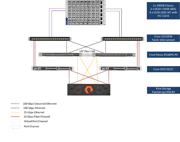
Figure 16 details the physical hardware and cabling deployed to enable this solution:
● Two Cisco Nexus 93180YC-FX Switches in NX-OS Mode.
● Two Cisco MDS 9132T 32-Gb Fibre Channel Switches.
● One Cisco UCS 9508 Chassis with two Cisco UCS-IFM-9108 100GB Modules.
● Eight Cisco UCS X210C M7 Blade Servers with Intel(R) Xeon(R) Gold 6448 CPU 2.40GHz 32-core processors, 2TB 4800MHz RAM, and one Cisco VIC 15231 mezzanine card, providing N+1 server fault tolerance.
● Pure Storage FlashArray//50 R4 with dual redundant controllers, with Twenty 1.92TB DirectFlash NVMe drives.
Note: The management components and LoginVSI Test infrastructure are hosted on a separate vSphere cluster and are not a part of the physical topology of this solution.
Table 2 lists the software versions of the primary products installed in the environment.
Table 2. Software and Firmware Versions
| Vendor |
Product/Component |
Version/Build/Code |
| Cisco |
UCS Component Firmware |
4.3(2.240002) |
| Cisco |
UCS X210C M7 Compute Node |
5.2(0.230127) |
| Cisco |
VIC 15231 (Virtual Interface Card) |
5.2(0.230127) |
| Cisco |
Cisco Nexus 93180YC-FX Switches |
9.3(7a) |
| Cisco |
Cisco MDS 9132T |
8.5(1a) |
| Pure Storage |
FlashArray//50 R4 |
Purity//FA 6.4.10 |
| VMware |
vCenter Server Appliance |
8.0.2 |
| VMware |
vSphere 8. 0. 2 |
8.0.2 |
| Citrix |
Citrix Virtual Apps and Desktops 2203 |
2203 LTSR FR3 |
| Cisco |
Intersight Assist |
1.0.11-1629 |
| Microsoft |
FSLogix 2210 hotfix 3 (User Profile Mgmt.) |
2.9.8784.63912 |
| VMware |
Tools |
12.2.0.21223074 |
The logical architecture of the validated solution which is designed to run desktop and RDSH server VMs supporting up to 1800 users on a single chassis containing 8 blades, with physical redundancy for the blade servers for each workload type and have a separate vSphere cluster to host management services, is illustrated in Figure 17.
Note: Separating management components and desktops is a best practice for the large environments.
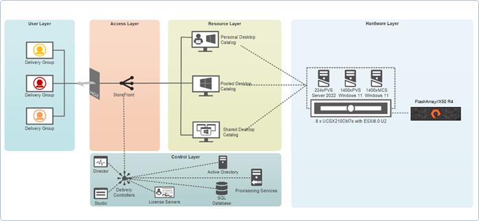
Two VMware Clusters in separate vCenter datacenters were utilized to support the solution and testing environment:
● VDI Cluster Flashstack Datacenter with Cisco UCS
◦ VDI Workload VMs (Windows Server 2022 streamed RDS Server VMs with Citrix Virtual Apps and Desktops for Remote Desktop Server Hosted (RDSH) Sessions, Windows 11 Streamed with Citrix Virtual Apps and Desktops PVS (non-persistent) and MCS Full Cloned (persistent) desktops.
● Management Services Cluster
◦ Infrastructure: Infra VMs (vCenter, Active Directory, DNS, DHCP, SQL Server, Citrix Virtual Apps and Desktops Studio Servers, Citrix Virtual Apps and Desktops Storefront Servers, VMware vSphere, VSMs, VSI Launchers and required VMs or plug in VMS so on).
For Example, the cluster(s) configured for running LoginVSI workload for measuring VDI End User Experience is LVS-Launcher-CLSTR: (The Login VSI infrastructure cluster consists of Login VSI data shares, LVSI Web Servers and LVSI Management Control VMs etc. were connected using the same set of Nexus switches and was hosted on separate set of UCS rack servers with local storage and managed by different vCenter. LVS-Launcher-CLSTR configured and used for the purpose of testing the LoginVSI End User Experience measurement for VMware RDSH multi server session and Win 11 VDI users.
The Citrix Virtual Apps and Desktops solution described in this document provides details for configuring a fully redundant, highly-available configuration. Configuration guidelines are provided that refer to which redundant component is being configured with each step, whether that be A or B. For example, Cisco Nexus A and Cisco Nexus B identify the pair of Cisco Nexus switches that are configured. The Cisco UCS Fabric Interconnects are configured similarly.
Note: This document is intended to allow the reader to configure the Citrix Virtual Apps and Desktops customer environment as a stand-alone solution.
VLANs
The VLAN configuration recommended for the environment includes a total of six VLANs as outlined in Table 3.
Table 3. VLANs Configured in this study
| VLAN Name |
VLAN ID |
VLAN Purpose |
| Default |
1 |
Native VLAN |
| FS-InBand-Mgmt_70 |
70 |
In-Band management interfaces |
| FS-Infra-Mgmt_71 |
71 |
Infrastructure Virtual Machines |
| FS-VDI_72 |
72 |
RDSH, VDI Persistent and Non-Persistent |
| FS-vMotion_73 |
73 |
VMware vMotion |
| OOB-Mgmt_164 |
164 |
Out of Band management interfaces |
VSANs
Table 4 lists the two virtual SANs that were configured for communications and fault tolerance in this design.
Table 4. VSANs Configured in this study
| VSAN Name |
VSAN ID |
VSAN Purpose |
| VSAN 100 |
100 |
VSAN for Primary SAN communication |
| VSAN 101 |
101 |
VSAN for Secondary SAN communication |
This chapter contains the following:
The following sections detail the physical connectivity configuration of the FlashStack Citrix Virtual Apps and Desktops VDI environment.
The information provided in this section is a reference for cabling the physical equipment in this Cisco Validated Design environment. To simplify cabling requirements, the tables include both local and remote device and port locations.
The tables in this section list the details for the prescribed and supported configuration of the Pure Storage FlashArray//x50 R4 storage array to the Cisco 6536 Fabric Interconnects through Cisco MDS 9132T 32-Gb FC switches.
Note: This document assumes that out-of-band management ports are plugged into an existing management infrastructure at the deployment site. These interfaces will be used in various configuration steps.
Note: Be sure to follow the cabling directions in this section. Failure to do so will result in problems with your deployment.
Figure 18 details the cable connections used in the validation lab for FlashStack topology based on the Cisco UCS 6536 fabric interconnect. Four 32Gb uplinks connect as port-channels to each Cisco UCS Fabric Interconnect from the MDS switches, and a total of eight 32Gb links connect the MDS switches to the Pure Storage FlashArray//X R4 controllers, four of these have been used for scsi-fc and the other four to support nvme-fc. Also, the 25Gb links connect the Cisco UCS Fabric Interconnects to the Cisco Nexus Switches and the Pure Storage FlashArray//X R4 controllers to the Cisco Nexus Switches. Additional 1Gb management connections will be needed for an out-of-band network switch that sits apart from the FlashStack infrastructure. Each Cisco UCS fabric interconnect and Cisco Nexus switch is connected to the out-of-band network switch, and each FlashArray controller has a connection to the out-of-band network switch. Layer 3 network connectivity is required between the Out-of-Band (OOB) and In-Band (IB) Management Subnets.
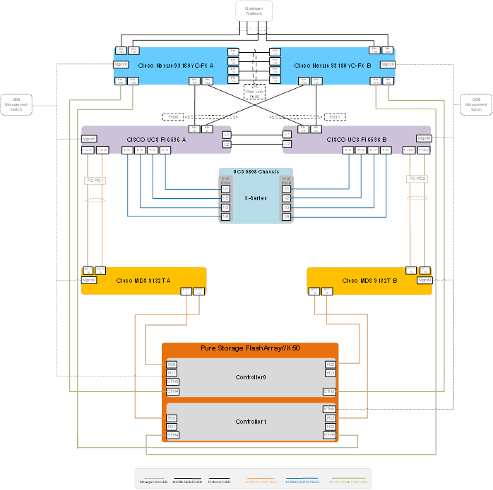
Configuration and Installation
This chapter contains the following:
● FlashStack Automated Deployment with Ansible
● FlashStack Manual Deployment
● Cisco UCS X-Series M7 Configuration – Intersight Managed Mode (IMM)
● Configure a Cisco UCS Domain Profile
● Configure Cisco UCS Chassis Profile
● Cisco MDS 9132T 32-Gb FC Switch Configuration
● Configure Pure Storage FlashArray//X50 R4
● Configure Host, WWNs, and Volume Connectivity with FlashArray Management Tools
● Install and Configure VMware ESXi 8.0
● Cisco Intersight Orchestration
FlashStack Automated Deployment with Ansible
This solution offers Ansible Playbooks that are made available from a GitHub repository that you can access to automate the FlashStack deployment.
GitHub repository is available here: https://github.com/ucs-compute-solutions/FlashStack_IMM_Ansible.
This repository contains Ansible playbooks to configure all the components of FlashStack including:
● Cisco UCS in Intersight Managed Mode (IMM)
● Cisco Nexus and MDS Switches
● Pure Storage FlashArray
● VMware ESXi and VMware vCenter
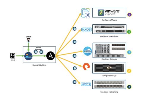
Cisco Intersight Managed Mode standardizes policy and operation management for Cisco UCS X-Series M7. The compute nodes in Cisco UCS X-Series M7 are configured using server profiles defined in Cisco Intersight. These server profiles derive all the server characteristics from various policies and templates. At a high level, configuring Cisco UCS using Cisco Intersight Managed Mode consists of the steps shown in Figure 20.
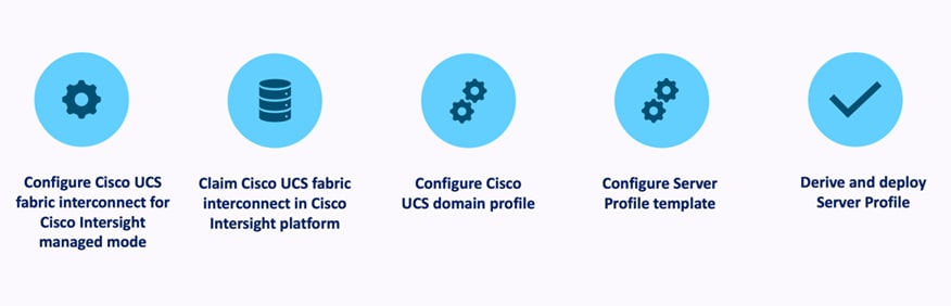
Cisco UCS X-Series M7 Configuration – Intersight Managed Mode (IMM)
Procedure 1. Configure Cisco UCS Fabric Interconnects for IMM
Step 1. Verify the following physical connections on the fabric interconnect:
● The management Ethernet port (mgmt0) is connected to an external hub, switch, or router.
● The L1 ports on both fabric interconnects are directly connected to each other.
● The L2 ports on both fabric interconnects are directly connected to each other.
Step 2. Connect to the console port on the first Fabric Interconnect.
Step 3. Configure Fabric Interconnect A (FI-A). On the Basic System Configuration Dialog screen, set the management mode to Intersight. All the remaining settings are similar to those for the Cisco UCS Manager managed mode (UCSM-Managed).
Cisco UCS Fabric Interconnect A
Procedure 1. Configure the Cisco UCS for use in Intersight Managed Mode
Step 1. Connect to the console port on the first Cisco UCS fabric interconnect:
Enter the configuration method. (console/gui) ? console
Enter the management mode. (ucsm/intersight)? intersight
You have chosen to setup a new Fabric interconnect in “intersight” managed mode. Continue? (y/n): y
Enforce strong password? (y/n) [y]: Enter
Enter the password for "admin": <password>
Confirm the password for "admin": <password>
Enter the switch fabric (A/B) []: A
Enter the system name: <ucs-cluster-name>
Physical Switch Mgmt0 IP address : <ucsa-mgmt-ip>
Physical Switch Mgmt0 IPv4 netmask : <ucsa-mgmt-mask>
IPv4 address of the default gateway : <ucsa-mgmt-gateway>
Configure the DNS Server IP address? (yes/no) [n]: y
DNS IP address : <dns-server-1-ip>
Configure the default domain name? (yes/no) [n]: y
Default domain name : <ad-dns-domain-name>
<SNIP>
Verify and save the configuration.
Step 2. After applying the settings, make sure you can ping the fabric interconnect management IP address. When Fabric Interconnect A is correctly set up and is available, Fabric Interconnect B will automatically discover Fabric Interconnect A during its setup process as shown in the next step.
Step 3. Configure Fabric Interconnect B (FI-B). For the configuration method, choose console. Fabric Interconnect B will detect the presence of Fabric Interconnect A and will prompt you to enter the admin password for Fabric Interconnect A. Provide the management IP address for Fabric Interconnect B and apply the configuration.
Cisco UCS Fabric Interconnect B
Enter the configuration method. (console/gui) ? console
Installer has detected the presence of a peer Fabric interconnect. This Fabric interconnect will be added to the cluster. Continue (y/n) ? y
Enter the admin password of the peer Fabric interconnect: <password>
Connecting to peer Fabric interconnect... done
Retrieving config from peer Fabric interconnect... done
Peer Fabric interconnect Mgmt0 IPv4 Address: <ucsa-mgmt-ip>
Peer Fabric interconnect Mgmt0 IPv4 Netmask: <ucsa-mgmt-mask>
Peer FI is IPv4 Cluster enabled. Please Provide Local Fabric Interconnect Mgmt0 IPv4 Address
Physical Switch Mgmt0 IP address : <ucsb-mgmt-ip>
Local fabric interconnect model(UCS-FI-6536)
Peer fabric interconnect is compatible with the local fabric interconnect. Continuing with the installer...
Apply and save the configuration (select 'no' if you want to re-enter)? (yes/no): yes
Procedure 2. Claim a Cisco UCS Fabric Interconnect in the Cisco Intersight Platform
If you do not already have a Cisco Intersight account, you need to set up a new account in which to claim your Cisco UCS deployment. Start by connecting to https://intersight.com.
All information about Cisco Intersight features, configurations can be accessed in the Cisco Intersight Help Center.
Step 1. Click Create an account.
Step 2. Sign in with your Cisco ID.
Step 3. Read, scroll through, and accept the end-user license agreement. Click Next.
Step 4. Enter an account name and click Create.
If you have an existing Cisco Intersight account, connect to https://intersight.com and sign in with your Cisco ID, select the appropriate account.
Note: In this step, a Cisco Intersight organization is created where all Cisco Intersight managed mode configurations including policies are defined.
Step 5. Log into the Cisco Intersight portal as a user with account administrator role.
Step 6. From the Service Selector drop-down list, select System.
Step 7. Navigate to Settings > General > Resource Groups.
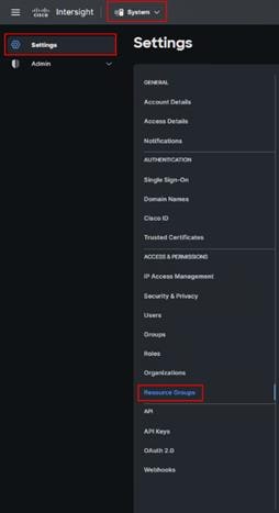
Step 8. On Resource Groups panel click + Create Resource Group in the top-right corner.
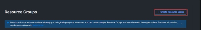
Step 9. Provide a name for the Resource Group (for example, L151-DMZ-DMZ-FSGEN5).
Step 10. Click Create.
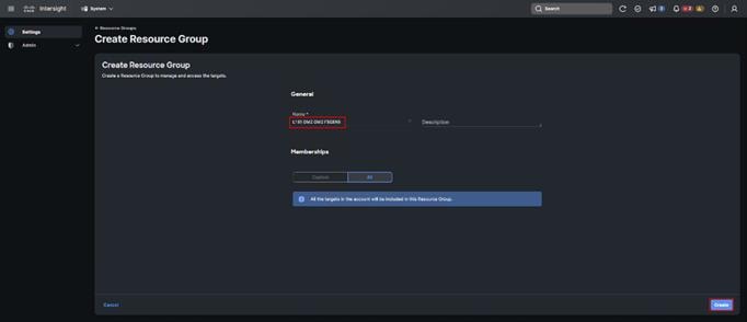
Step 11. Navigate to System > Settings > ACCESS & PERMISSIONS > Organizations.
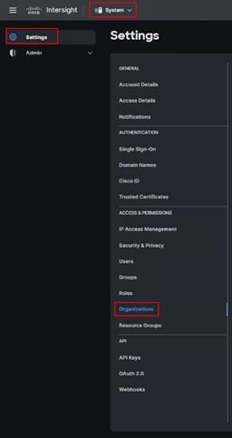
Step 12. On Organizations panel click + Create Organization in the top-right corner.
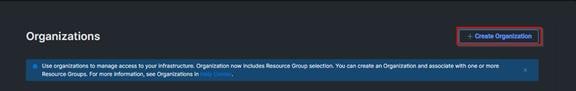
Step 13. Provide a name for the organization (FlashStack-Gen5).
Step 14. Click Next.
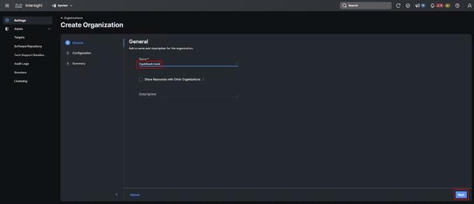
Step 15. Select the Resource Group created in the last step (for example, FlashStack-L151-DMZ).
Step 16. Click Next.
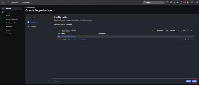
Step 17. Click Create.
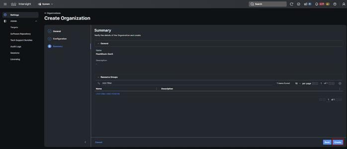
Step 18. Use the management IP address of Fabric Interconnect A to access the device from a web browser and the previously configured admin password to log into the device.
Step 19. Under DEVICE CONNECTOR, the current device status will show “Not claimed.” Note, or copy, the Device ID, and Claim Code information for claiming the device in Cisco Intersight.
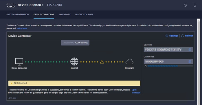
Step 20. Navigate to System > Admin > General > Targets.
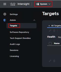
Step 21. On Targets panel click Claim a New Target in the top-right corner.
![]()
Step 22. Select Cisco UCS Domain (Intersight Managed) and click Start.
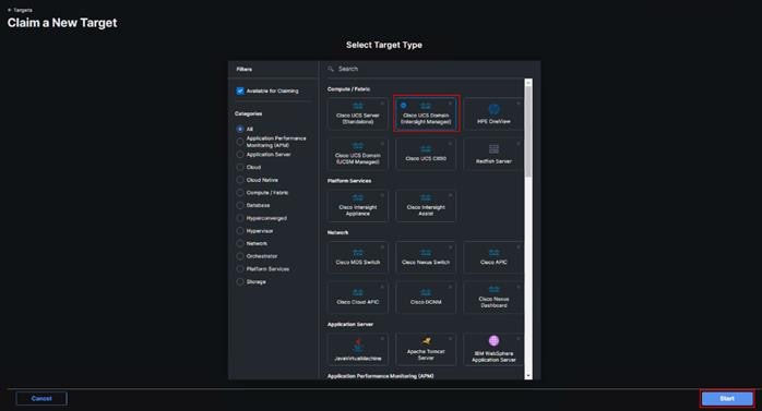
Step 23. Enter the Device ID and Claim Code captured from the Cisco UCS FI.
Step 24. Click Claim.
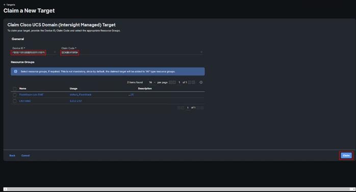
Step 25. On successfully device claim, Cisco UCS FI should appear as a target in Cisco Intersight.
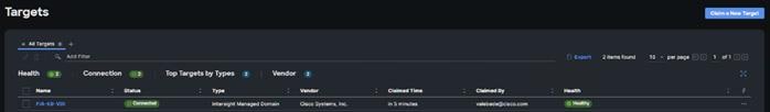
Configure a Cisco UCS Domain Profile
A Cisco UCS domain profile configures a fabric interconnect pair through reusable policies, allows configuration of the ports and port channels, and configures the VLANs and VSANs in the network. It defines the characteristics of and configured ports on fabric interconnects. The domain-related policies can be attached to the profile either at the time of creation or later. One Cisco UCS domain profile can be assigned to one fabric interconnect domain.
After the Cisco UCS domain profile has been successfully created and deployed, the policies including the port policies are pushed to Cisco UCS Fabric Interconnects. Cisco UCS domain profile can easily be cloned to install additional Cisco UCS systems. When cloning the UCS domain profile, the new UCS domains utilize the existing policies for consistent deployment of additional Cisco UCS systems at scale.
Procedure 1. Create a Domain Profile
Step 1. From the Service Selector drop-down list, select Infrastructure Service. Navigate to Configure > Profiles, to launch the Profiles Table view.
Step 2. Navigate UCS Domain Profiles tab.
Step 3. Click Create UCS Domain Profile.
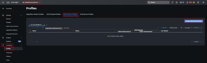
Step 4. On the Create UCS Domain Profile screen, click Start.
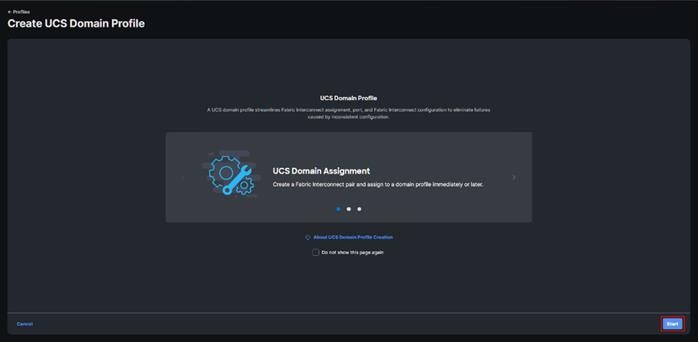
Step 5. On the General page, select the organization created before and enter a name for your profile (for example, L152-DMZ-K8). Optionally, include a short description and tag information to help identify the profile. Tags must be in the key:value format. For example, Org: IT or Site: APJ. Click Next.
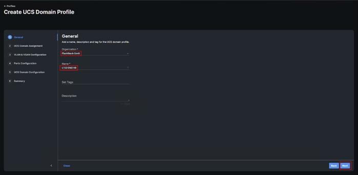
Step 6. On the Domain Assignment page, assign a switch pair to the Domain profile. Click Next.
Note: You can also click Assign Later and assign a switch pair to the Domain profile at a later time.
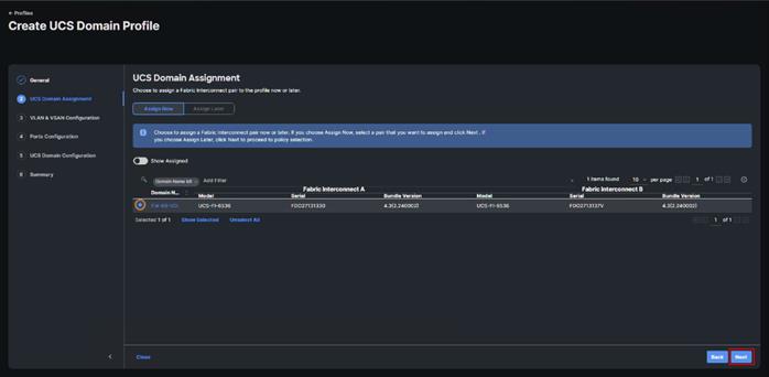
Step 7. On the VLAN & VSAN Configuration page, attach VLAN and VSAN policies for each switch to the UCS Domain Profile.
In this step, a single VLAN policy is created for both fabric interconnects and two individual VSAN policies are created because the VSAN IDs are unique for each fabric interconnect.
Step 8. Click Select Policy next to VLAN Configuration under Fabric Interconnect A.
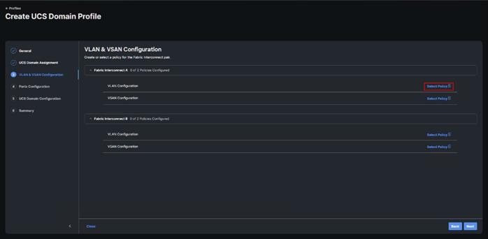
Step 9. In the pane on the right, click Create New.
Step 10. Verify correct organization is selected from the drop-down list and provide a name for the policy (for example, L152-DMZ-GEN5-VLAN). Click Next.
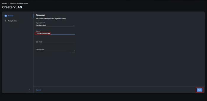
Step 11. Click Add VLANs.
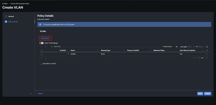
Step 12. Provide a name and VLAN ID for the VLAN from you list (for example, 70, 71, 72, 73). Enable Auto Allow On Uplinks. To create the required Multicast policy, click Select Policy under Multicast*.
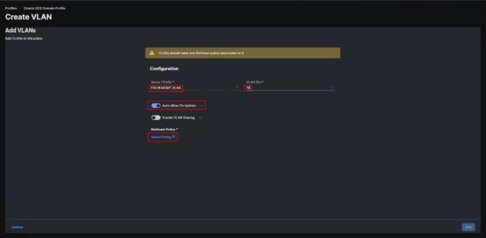
Step 13. In the window on the right, click Create New to create a new Multicast Policy.
Step 14. Provide a Name for the Multicast Policy (for example, FS-L152-DMZ-McastPol). Provide an optional Description and click Next.
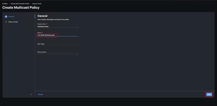
Step 15. Leave defaults selected and click Create.
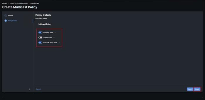
Step 16. Click Add to add the VLAN.
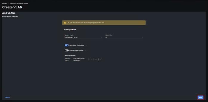
Step 17. Add the remaining VLANs from you list by clicking Add VLANs and entering the VLANs one by one. Reuse the previously created multicast policy for all the VLANs.
The VLANs created during this validation are shown below:
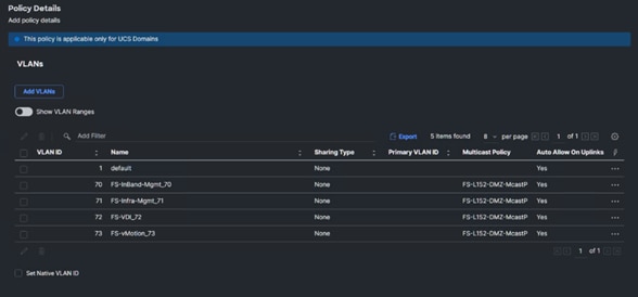
Step 18. A VSAN policy is only needed when configuring Fibre Channel and can be skipped when configuring IP-only storage access.
Step 19. Click Select Policy next to VSAN Configuration under Fabric Interconnect A. Click Create New.
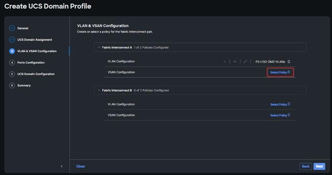
Step 20. Verify correct organization is selected from the drop-down list and provide a name for the policy (for example, FS-L152-DMZ-VSAN-A). Click Next.
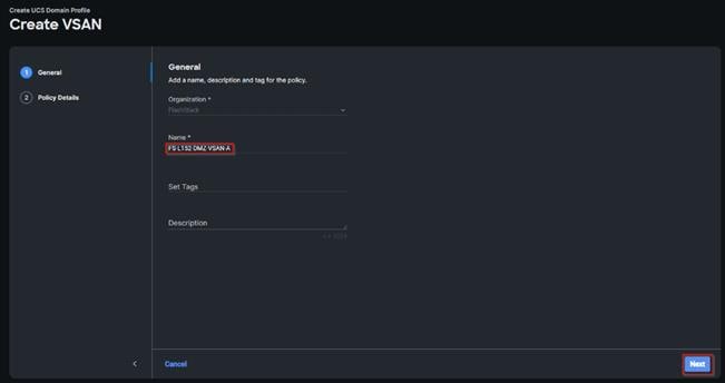
Step 21. Click Add VSAN.
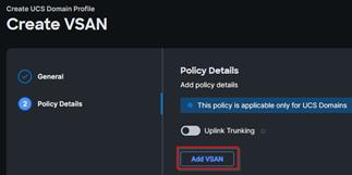
Step 22. Provide a name (for example, VSAN-A), VSAN ID (for example, 100), and associated Fibre Channel over Ethernet (FCoE) VLAN ID (for example, 100) for VSAN A.
Step 23. Set VLAN Scope as Uplink.
Step 24. Click Add.
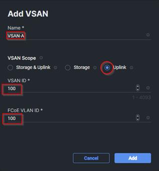
Step 25. Click Create to finish creating VSAN policy for fabric A.
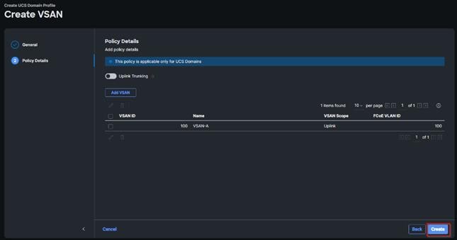
Step 26. Repeat steps 7 - 25 for fabric interconnect B assigning the VLAN policy created previously and creating a new VSAN policy for VSAN-B. Name the policy to identify the SAN-B configuration (for example, FS-L152-DMZ-VSAN-B) and use appropriate VSAN and FCoE VLAN (for example, 101).
Step 27. Verify that a common VLAN policy and two unique VSAN policies are associated with the two fabric interconnects. Click Next.
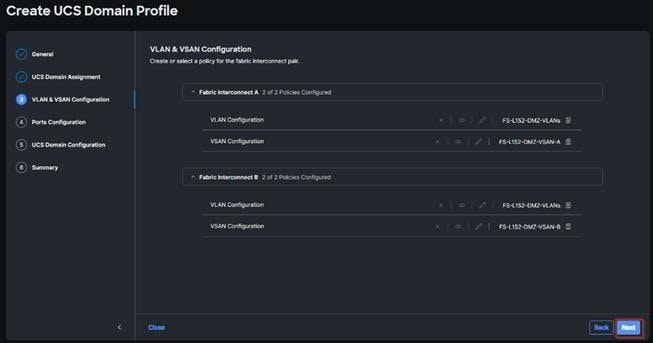
Step 28. On the Ports Configuration page, attach port policies for each switch to the UCS Domain Profile.
Note: Use two separate port policies for the fabric interconnects. Using separate policies provide flexibility when port configuration (port numbers or speed) differs between the two FIs. When configuring Fibre Channel, two port policies are required because each fabric interconnect uses unique Fibre Channel VSAN ID.
Step 29. Click Select Policy for Fabric Interconnect A.
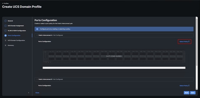
Step 30. Click Create New.
Step 31. Verify the correct organization is selected from the drop-down list and provide a name for the policy (for example, FS-L152-DMZ-K8-GEN5-FI-A). Click Next.
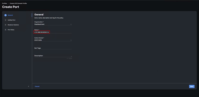
Step 32. Move the slider to set up unified ports. In this deployment, the two ports (35-36) were selected as Fibre Channel ports. Click Next.
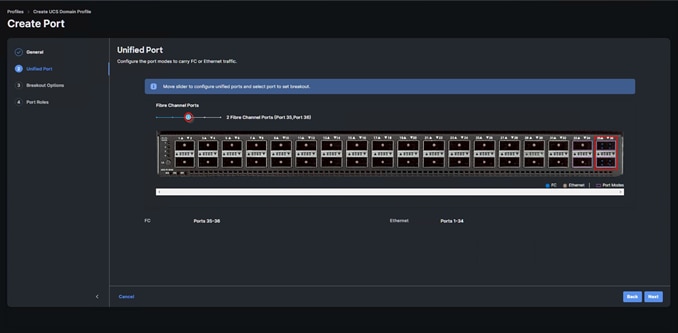
Step 33. On the breakout Options page click Next.
Note: No Ethernet/Fibre Channel breakouts were used in this validation.
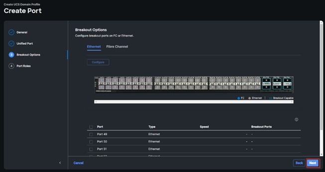
Step 34. Select the ports that need to be configured as server ports by clicking the ports in the graphics (or select from the list below the graphic). When all ports are selected, click Configure.
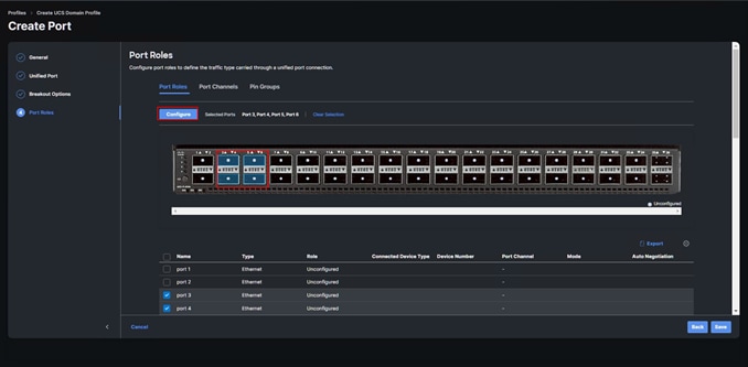
Step 35. From the drop-down list, select Server as the role. Click Save.
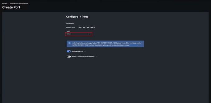
Step 36. Select the ports that need to be configured as Ethernet uplink ports by clicking the ports in the graphics (or select from the list below the graphic). When all ports are selected, click Configure.
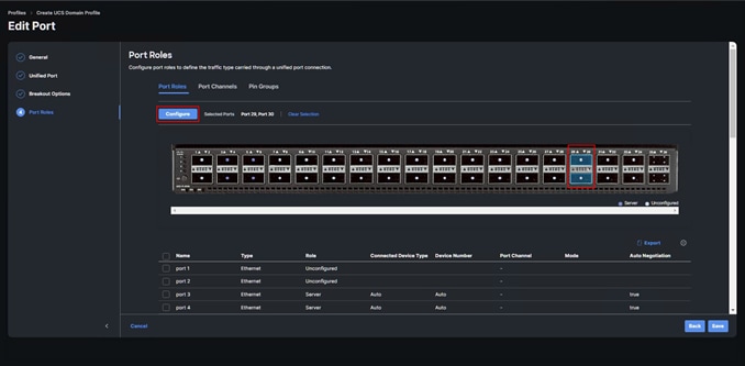
Step 37. From the drop-down list, select Ethernet Uplink as the role.
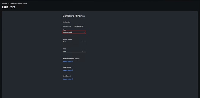
Step 38. Click Select Policy next to Flow Control and click Create New to define the Flow Control policy.
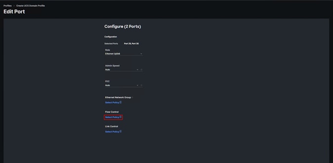
Step 39. Verify correct organization is selected from the drop-down list and provide a name for the policy (for example, L152-DMZ-GEN5-FlowCtrl). Click Next.
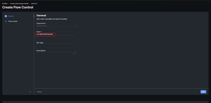
Step 40. Keep the default selections. Click Create.
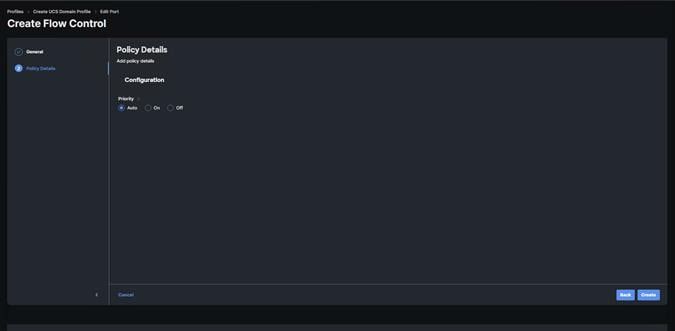
Step 41. Click Select Policy next to Link Control and click Create New to define the Link Control policy.
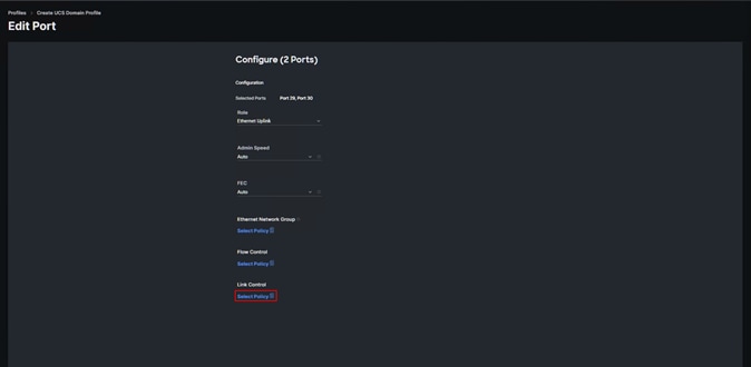
Step 42. Verify correct organization is selected from the drop-down list and provide a name for the policy (for example, L152-DMZ-GEN5-LinkCtrl). Click Next.
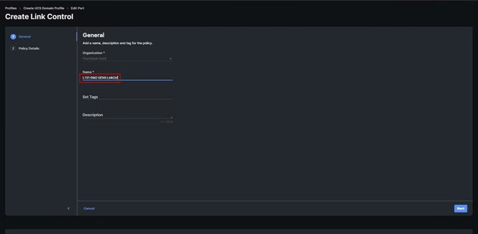
Step 43. Keep the default selections. Click Create.
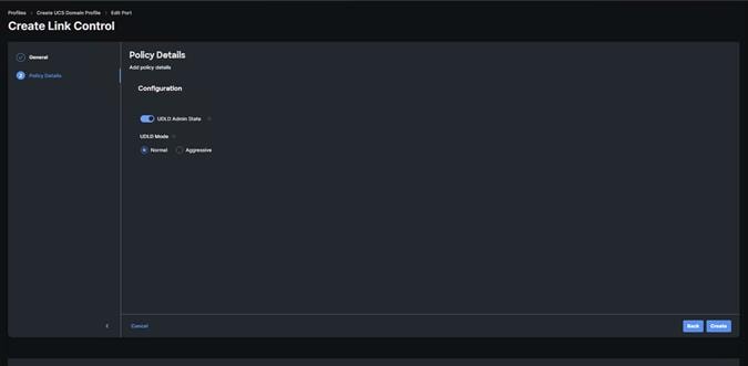
Step 44. Click Select Policy next to Link Control and click Create New to define the Link Control policy.
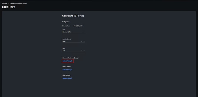
Step 45. Verify correct organization is selected from the drop-down list and provide a name for the policy (for example, L152-DMZ-GEN5-NetGroup). Click Next.
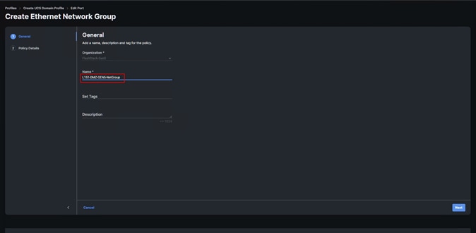
Step 46. Update Allowed VLANs list. Click Create.
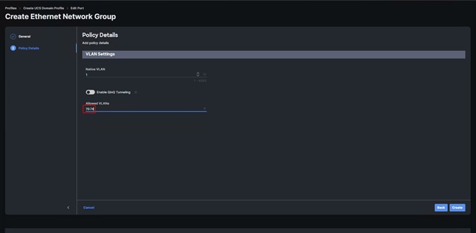
Step 47. Create port channel by selecting the Port Channel in the main pane and then clicking Create Port Channel.
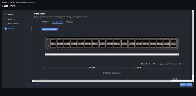
Step 48. Select Ethernet Uplink Port Channel as the role, provide a port-channel ID (for example, 39).
Note: You can create the Ethernet Network Group, Flow Control, Ling Aggregation or Link control policy for defining disjoint Layer-2 domain or fine tune port-channel parameters. These policies were not used in this deployment and system default values were utilized.
Step 49. Assign policies for Flow Control, link aggregation, and flow control created in a previous step. Scroll down and select uplink ports from the list of available ports (for example, port 29 and 30).
Step 50. Click Save.
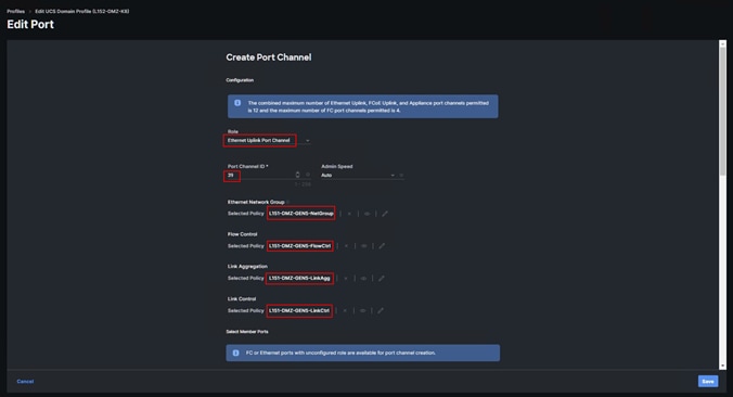
Step 51. Repeat the steps to create the port policy for Fabric Interconnect B. Use the following values for various parameters:
● Name of the port policy: L152-DMZ-K8-FI-B
● Ethernet port-Channel ID: 40
Step 52. When the port configuration for both fabric interconnects is complete and looks correct, click Next.
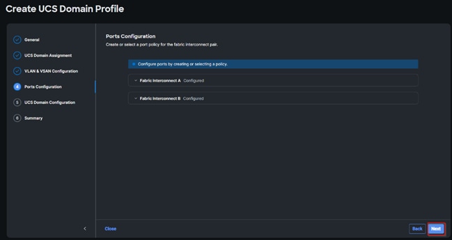
Step 53. Under UCS domain configuration, additional policies can be configured to setup NTP, Syslog, DNS settings, SNMP, QoS and UCS operating mode (end host or switch mode). For this deployment, System QoS will be configured.
Step 54. Click Select Policy next to System QoS* and click Create New to define the System QOS policy.
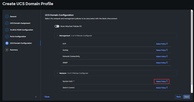
Step 55. Verify correct organization is selected from the drop-down list and provide a name for the policy (for example, FS-L152-DMZ-QosPol). Click Next.
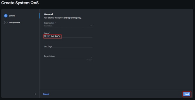
Step 56. Change the MTU for Best Effort class to 9216. Keep the rest default selections. Click Create.
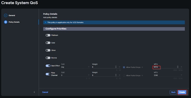
Step 57. Click Next.
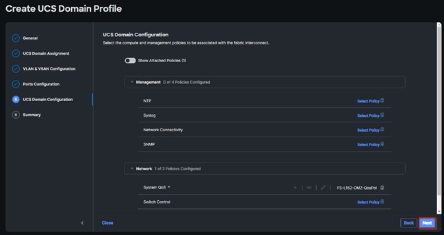
Step 58. From the UCS domain profile Summary view, Verify all the settings including the fabric interconnect settings, by expanding the settings and make sure that the configuration is correct. Click Deploy.
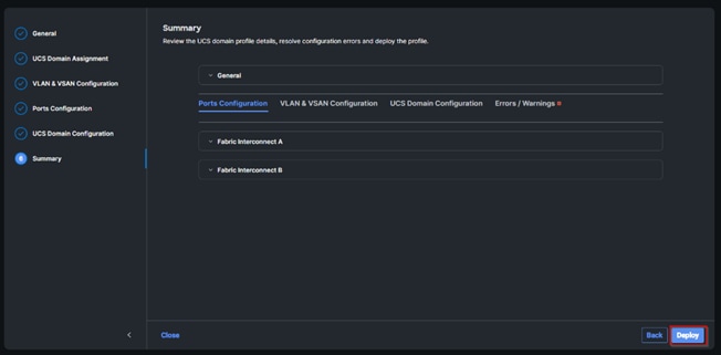
Step 59. The system will take some time to validate and configure the settings on the fabric interconnects. Log into the console servers to see when the Cisco UCS fabric interconnects have finished configuration and are successfully rebooted.
When the Cisco UCS domain profile has been successfully deployed, the Cisco UCS chassis and the blades should be successfully discovered.
It takes a while to discover the blades for the first time. Cisco Intersight provides an ability to view the progress in the Requests page:

Step 60. From the Service Selector drop-down list, select Infrastructure Service. Navigate to Configure > Profiles, select UCS Domain Profiles, verify that the domain profile has been successfully deployed.
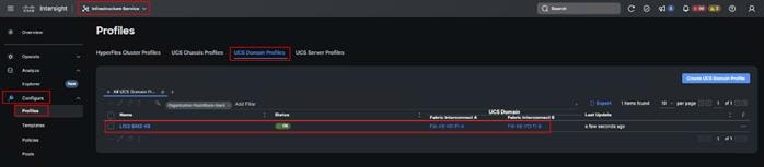
Step 61. From the Service Selector drop-down list, select Infrastructure Service. Navigate to Operate > Chassis, verify that the chassis has been discovered.
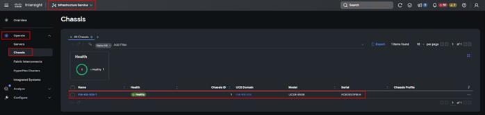
Step 62. From the Service Selector drop-down list, select Infrastructure Service. Navigate to Operate > Servers, verify that the servers have been successfully discovered.
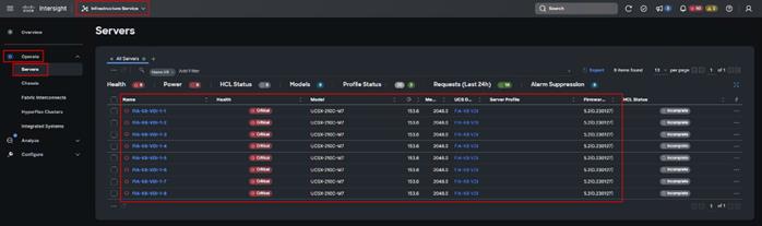
Configure Cisco UCS Chassis Profile
Cisco UCS Chassis profile in Cisco Intersight allows you to configure various parameters for the chassis, including:
● IMC Access Policy: IP configuration for the in-band chassis connectivity. This setting is independent of Server IP connectivity and only applies to communication to and from chassis.
● SNMP Policy, and SNMP trap settings.
● Power Policy to enable power management and power supply redundancy mode.
● Thermal Policy to control the speed of FANs.
A chassis policy can be assigned to any number of chassis profiles to provide a configuration baseline for a chassis. In this deployment, chassis profile was created and attached to the chassis with following settings shown in Figure 21.
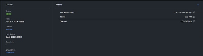

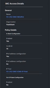
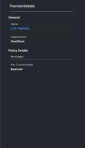
Configure Server Profile Template
In the Cisco Intersight platform, a server profile enables resource management by simplifying policy alignment and server configuration. The server profiles are derived from a server profile template. The server profile template and its associated policies can be created using the server profile template wizard. After creating server profile template, you can derive multiple consistent server profiles from the template.
Note: The server profile captured in this deployment guide supports both Cisco UCS X-Series Blade Servers and Cisco UCS X210c M6 Compute Nodes.
Procedure 1. Create Server Profile Template
In this deployment, four vNICs and two vHBAs are configured. These devices are manually placed as listed in Table 5.
Table 5. vHBA and vNIC placement for FC connected storage
| vNIC/vHBA Name |
Slot |
Switch ID |
PCI Order |
| vHBA-A |
MLOM |
A |
0 |
| vHBA-B |
MLOM |
B |
1 |
| 01-vSwitch0-A |
MLOM |
A |
2 |
| 02-vSwitch0-B |
MLOM |
B |
3 |
| 03-VDS0-A |
MLOM |
A |
4 |
| 04-VDS0-B |
MLOM |
B |
5 |
Note: Two vHBAs (vHBA-A and vHBA-B) are configured to support FC boot from SAN.
Step 1. Log into the Cisco Intersight portal as a user with account administrator role.
Step 2. Navigate to Configure > Templates and click Create UCS Server Profile Template.
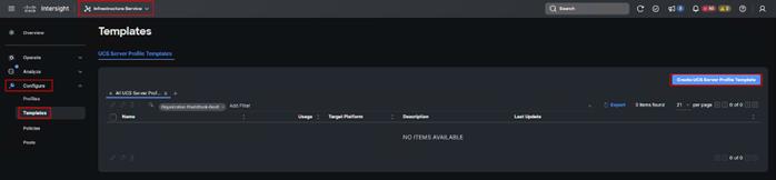
Step 3. Select the organization from the drop-down list. Provide a name for the server profile template (for example, L151-DMZ-GEN5- K8-X210CM7_TMPL) for FI-Attached UCS Server. Click Next.
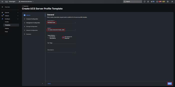
Step 4. Click Select Pool under UUID Pool and then click Create New.
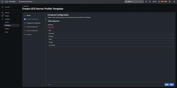
Step 5. Verify correct organization is selected from the drop-down list and provide a name for the UUID Pool (for example, L151-DMZ-GEN5-UUID_Pool). Provide an optional Description and click Next.
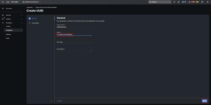
Step 6. Provide a UUID Prefix (for example, a random prefix of 32313531-6B38-0000was used). Add a UUID block of appropriate size. Click Create.
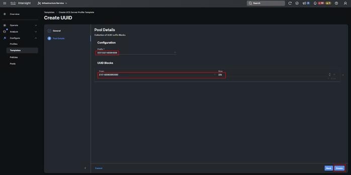
Step 7. Click Select Policy next to BIOS and in the pane on the right, click Create New.
Step 8. Verify the correct organization is selected from the drop-down list and provide a name for the policy (for example, L151-DMZ-GEN5-M7-BIOS-Perf_Pol).
Step 9. Click Next.

Step 10. On the Policy Details screen, select appropriate values for the BIOS settings. Click Create.
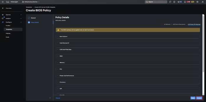
In this deployment, the BIOS values were selected based on recommendations in the performance tuning guide for Cisco UCS M7 Platforms.
Table 6. FS-L151-DMZ-M7-BIOS-Perf Token Values
| BIOS Token |
Value |
| Intel Directed IO |
|
| Intel VT for Directed IO |
enabled |
| Memory |
|
| Memory RAS Configuration |
maximum-performance |
| Power And Performance |
|
| Core Performance Boost |
Auto |
| Enhanced CPU Performance |
Auto |
| LLC Dead Line |
disabled |
| UPI Link Enablement |
1 |
| UPI Power Management |
enabled |
| Processor |
|
| Altitude |
auto |
| Boot Performance Mode |
Max Performance |
| Core Multi Processing |
all |
| CPU Performance |
enterprise |
| Power Technology |
performance |
| Direct Cache Access Support |
enabled |
| DRAM Clock Throttling |
Performance |
| Enhanced Intel Speedstep(R) Technology |
enabled |
| Execute Disable Bit |
enabled |
| IMC Interleaving |
1-way Interleave |
| Intel HyperThreading Tech |
Enabled |
| Intel Turbo Boost Tech |
enabled |
| Intel(R) VT |
enabled |
| DCU IP Prefetcher |
enabled |
| Processor C1E |
disabled |
| Processor C3 Report |
disabled |
| Processor C6 Report |
disabled |
| CPU C State |
disabled |
| Sub Numa Clustering |
enabled |
| DCU Streamer Prefetch |
enabled |
Step 11. Click Select Policy next to Boot Order and then click Create New.
Step 12. Verify correct organization is selected from the drop-down list and provide a name for the policy (for example, L151-DMZ-GEN5-BOOT_Pol). Click Next.
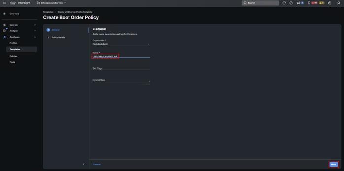
Step 13. For Configured Boot Mode, select Unified Extensible Firmware Interface (UEFI).
Step 14. Turn on Enable Secure Boot.
Step 15. Click Add Boot Device drop-down list and select Virtual Media.
Step 16. Provide a device name (for example, vKVM-DVD) and then, for the subtype, select KVM Mapped DVD.
Step 17. For Fibre Channel SAN boot, four connected FC ports on Pure Storage FlashArray//X50 R4 controllers will be added as boot options. The FC ports are as follows:
● CT0.FC4, CT1.FC4 are connected to SAN-A
● CT1.FC5, CT0.FC5 are connected to SAN-B
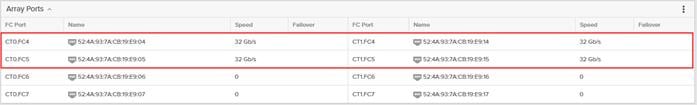
Step 18. From the Add Boot Device drop-down list, select SAN Boot (Repeat steps for all 4 FC ports)
Step 19. Provide the Device Name: CT0FC4 and the Logical Unit Number (LUN) value (for example, 1).
Step 20. Provide an interface name vHBA-A. This value is important and should match the vHBA name.
Step 21. vHBA-A is used to access CT0.FC4, CT1.FC4 and vHBA-B is used to access CT1.FC5, CT0.FC5.
Step 22. Add the appropriate World Wide Port Name (WWPN) as the Target WWPN (for example, 52:4A:93:7A:CB:19:E9:04).
Step 23. Provide bootloader name as BOOTX64.EFI.
Step 24. Provide bootloader name as \EFI\BOOT.
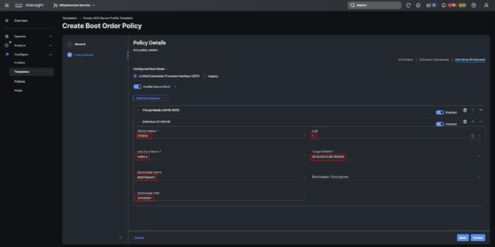
Step 25. Verify the order of the boot policies and adjust the boot order as necessary using the arrows next to delete icon ![]() . Click Create.
. Click Create.
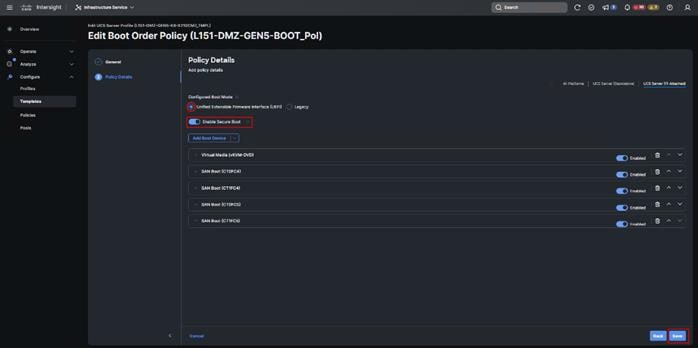
Step 26. Click Select Policy next to Power and in the pane on the right, click Create New.
Step 27. Verify the correct organization is selected from the drop-down list and provide a name for the policy (for example, L151-DMZ-GEN5-NODEPWRt_Pol). Click Next.
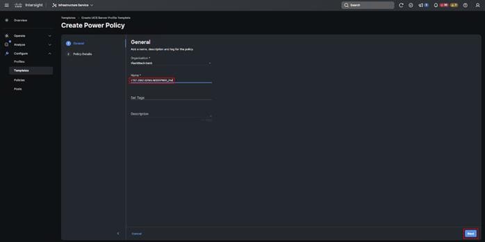
Step 28. Enable Power Profiling and select High from the Power Priority drop-down list. Click Create.
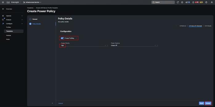
Step 29. Click Select Policy next to Virtual Media and in the pane on the right, click Create New (Optional)
Step 30. Verify the correct organization is selected from the drop-down list and provide a name for the policy (for example, L151-DMZ-GEN5-NODEVMED_Pol). Click Next.

Step 31. Disable Lower Power USB and click Create.
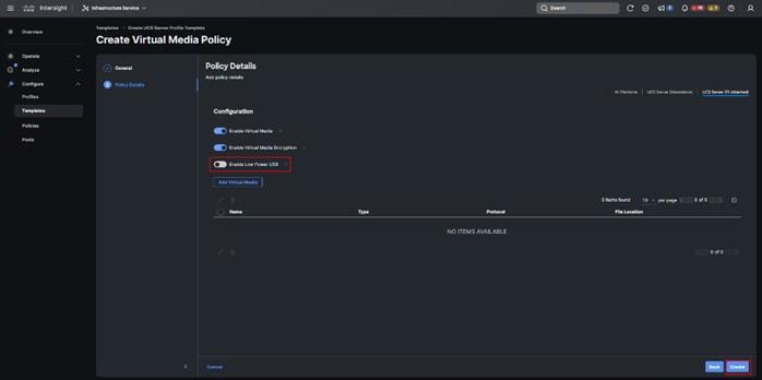
Step 32. Click Next to go to Management Configuration.
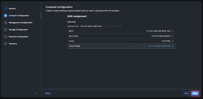
Step 33. Click Select Policy next to IMC Access and then click Create New.
Step 34. Verify the correct organization is selected from the drop-down list and provide a name for the policy (for example, L152-DMZ-GEN5-IMCACC_Pol). Click Next.
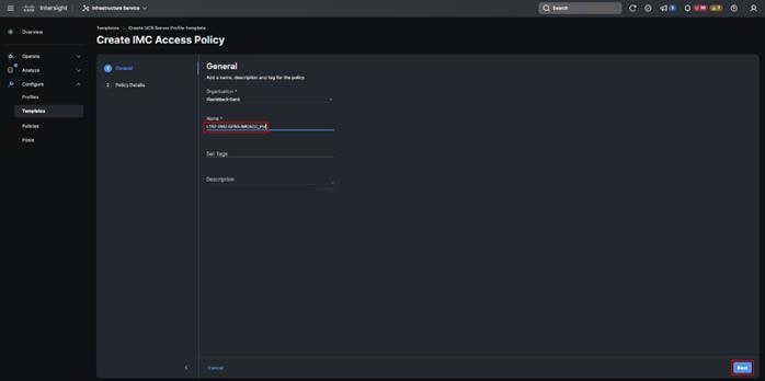
Note: You can select in-band management access to the compute node using an in-band management VLAN (for example, VLAN 70) or out-of-band management access using the Mgmt0 interfaces of the FIs. KVM Policies like SNMP, vMedia and Syslog are currently not supported using Out-Of-Band and will require an In-Band IP to be configured.
Step 35. Click UCS Server (FI-Attached). Enable In-Band Configuration and type VLAN Id designated for the In-Band management (for example, 70).
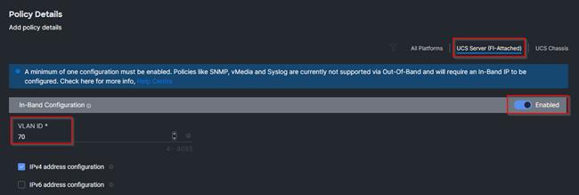
Step 36. Under IP Pool, click Select IP Pool and then click Create New.

Step 37. Verify the correct organization is selected from the drop-down list and provide a name for the policy (for example, L152-DMZ-GEN5-ICMACC-IPPool). Click Next.
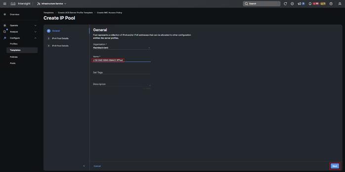
Step 38. Select Configure IPv4 Pool and provide the information to define a pool for KVM IP address assignment including an IP Block appropriate for your deployment.
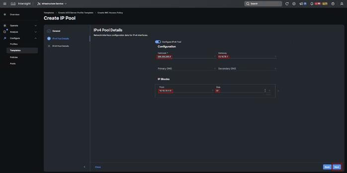
The management IP pool subnet should be accessible from the host that is trying to open the KVM connection. In the example shown here, the hosts trying to open a KVM connection would need to be able to route to 10.10.70.0/24 subnet:
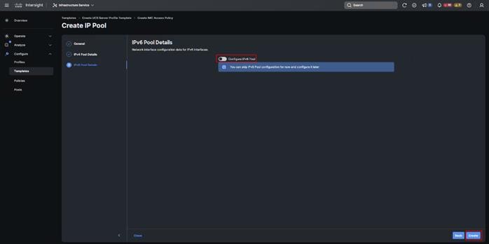
Step 39. Click Create to finish policy creation.
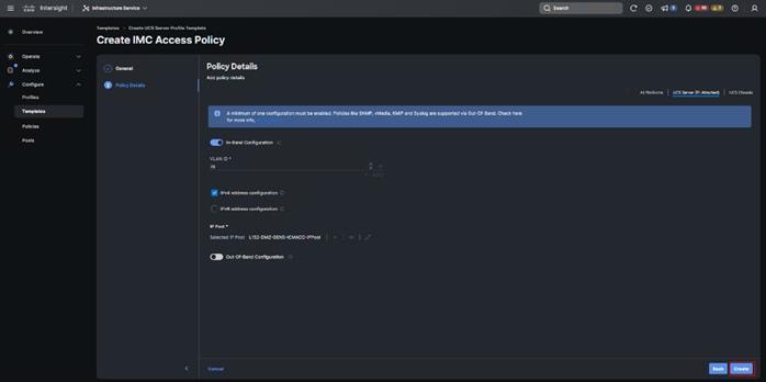
Step 40. Click Select Policy next to IPMI Over LAN and then click Create New.
Step 41. Verify the correct organization is selected from the drop-down list and provide a name for the policy (for example, Enable-IPMIoLAN). Click Next.
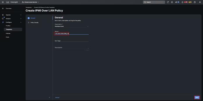
Step 42. Turn on Enable IPMI Over LAN.
Step 43. From the Privilege Level drop-down list, select admin.
Step 44. Click Create.
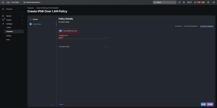
Step 45. Click Select Policy next to Local User and the, in the pane on the right, click Create New.
Step 46. Verify the correct organization is selected from the drop-down list and provide a name for the policy.
Step 47. Verify that UCS Server (FI-Attached) is selected.
Step 48. Verify that Enforce Strong Password is selected.
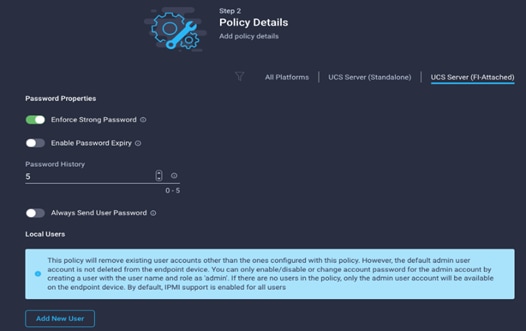
Step 49. Click Add New User and then click + next to the New User.
Step 50. Provide the username (for example, fpadmin), choose a role for example, admin), and provide a password.
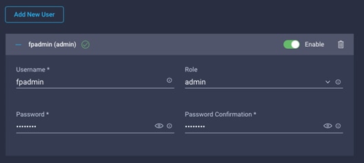
Note: The username and password combination defined here will be used to log into KVMs. The typical Cisco UCS admin username and password combination cannot be used for KVM access.
Step 51. Click Create to finish configuring the user.
Step 52. Click Create to finish configuring local user policy.
Step 53. Click Next to go to Storage Configuration.
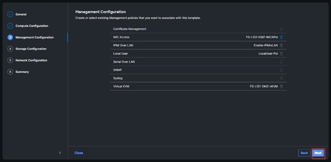
Step 54. Click Next on the Storage Configuration screen. No configuration is needed in the local storage system.
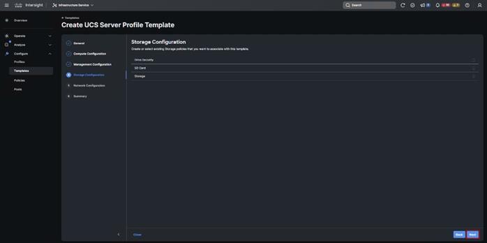
Step 55. Click Select Policy next to LAN Connectivity and then click Create New.
Note: LAN connectivity policy defines the connections and network communication resources between the server and the LAN. This policy uses pools to assign MAC addresses to servers and to identify the vNICs that the servers use to communicate with the network. For consistent vNIC placement, manual vNIC placement is utilized.
The FC boot from SAN hosts uses 4 vNICs configured as listed in Table 7.
Table 7. vNICs for LAN Connectivity
| vNIC |
Slot ID |
Switch ID |
PCI Order |
VLANs |
| vSwitch0-A |
MLOM |
A |
2 |
FS-InBand-Mgmt_70 |
| vSwitch0-B |
MLOM |
B |
3 |
FS-InBand-Mgmt_70 |
| VDS0-A |
MLOM |
A |
4 |
FS-VDI_72, FS-vMotion_73 |
| VDS0-B |
MLOM |
B |
5 |
FS-VDI_72, FS-vMotion_73 |
Note: The PCI order 0 and 1 will be used in the SAN Connectivity policy to create vHBA-A and vHBA-B.
Step 56. Verify the correct organization is selected from the drop-down list and provide a name for the policy (for example, L151-DMZ-K8-GEN5-LANConn_Pol). Click Next.
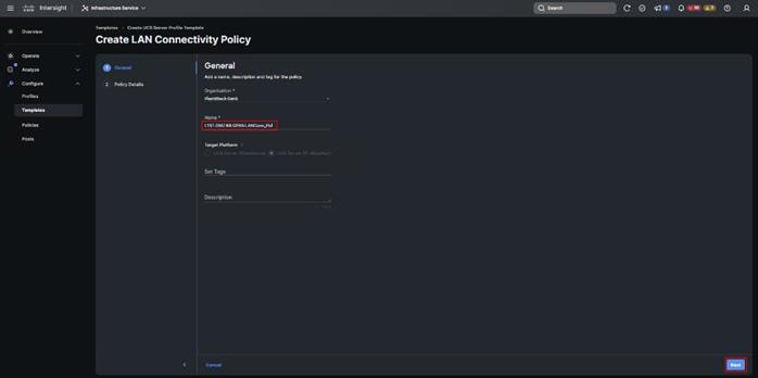
Step 57. Under vNIC Configuration, select Manual vNICs Placement.
Step 58. Click Add vNIC.
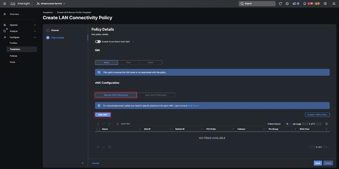
Step 59. Click Select Pool under MAC Address Pool and then click Create New.
When creating the first vNIC, the MAC address pool has not been defined yet, therefore a new MAC address pool will need to be created. Two separate MAC address pools are configured for each Fabric. MAC-Pool-A will be reused for all Fabric-A vNICs, and MAC-Pool-B will be reused for all Fabric-B vNICs.
| Pool Name |
Starting MAC Address |
Size |
vNICs |
| 00:25:B5:08:0A:00 |
256* |
vSwitch0-A, VDS0-A |
|
| L151-DMZ-GEN5-K8-MACPool-B |
00:25:B5:08:0B:00 |
256* |
vSwitch0-B, VDS0-B |
Step 60. Verify the correct organization is selected from the drop-down list and provide a name for the pool from Table 8 depending on the vNIC being created (for example, L151-DMZ-GEN5-K8-MACPool-A for Fabric A).
Step 61. Click Next.
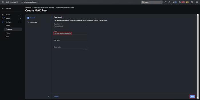
Step 62. Provide the starting MAC address from Table 8 (for example, 00:25:B5:04:0A:00) and the size of the MAC address pool (for example, 256). Click Create to finish creating the MAC address pool.
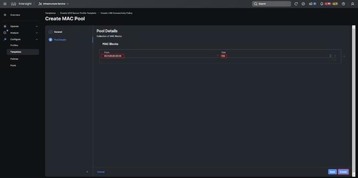
Step 63. From the Add vNIC window, provide vNIC Name, Slot ID, Switch ID, and PCI Order information from Table 7.
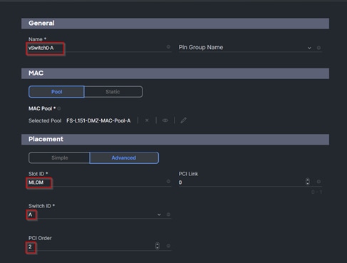
Step 64. For Consistent Device Naming (CDN), from the drop-down list, select vNIC Name.
Step 65. Verify that Failover is disabled because the failover will be provided by attaching multiple NICs to the VMware vSwitch and VDS.
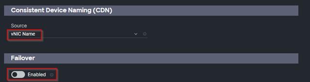
Step 66. Click Select Policy under Ethernet Network Group Policy and then click Create New.
The Ethernet Network Group policies will be created and reused on applicable vNICs as explained below. The Ethernet Network Group policy defines the VLANs allowed for a particular vNIC, therefore multiple network group policies will be defined for this deployment as listed in Table 9.
Table 9. Ethernet Group Policy Values
| Group Policy Name |
Native VLAN |
Apply to vNICs |
VLANs |
| FS-L151-DMZ-vSwitch0-NetGrp-Pol |
Native-VLAN (1) |
vSwitch0-A, vSwitch0-B |
FS-InBand-Mgmt_70 |
| FS-L151-DMZ-vSwitch1-NetGrp-Pol |
Native-VLAN (1) |
VDS0-A, VDS0-B |
FS-VDI_72, FS-vMotion_73 |
Step 67. Verify the correct organization is selected from the drop-down list and provide a name for the policy from Table 9 (for example, FS-L151-DMZ-vSwitch0-NetGrp-Pol). Click Next.
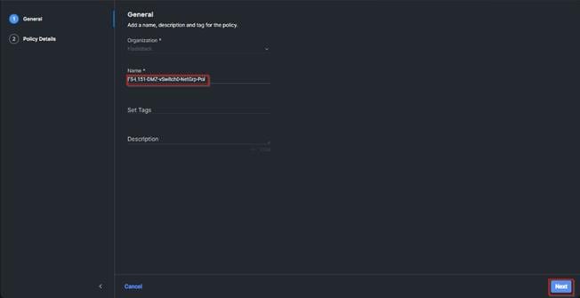
Step 68. Enter the allowed VLANs from Table 7 (for example, 70) and the native VLAN ID from Table 9 (for example, 1). Click Create.
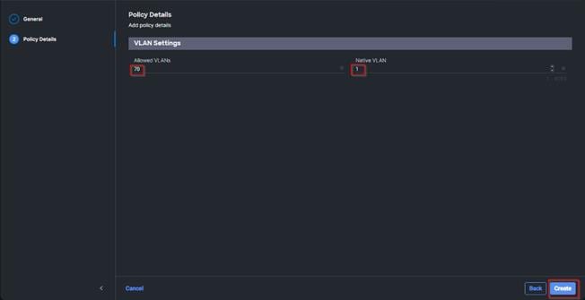
Step 69. When ethernet group policies are shared between two vNICs, the ethernet group policy only needs to be defined for the first vNIC. For subsequent vNIC policy mapping, click Select Policy and select the previously defined ethernet group policy from the list on the right.
Step 70. Click Select Policy under Ethernet Network Control Policy and then click Create New.
Note: The Ethernet Network Control Policy is used to enable Cisco Discovery Protocol (CDP) and Link Layer Discovery Protocol (LLDP) for the vNICs. A single policy will be created and reused for all the vNICs.
Step 71. Verify the correct organization is selected from the drop-down list and provide a name for the policy (for example, FS-L151-DMZ-NetCtrl-Pol).
Step 72. Click Next.
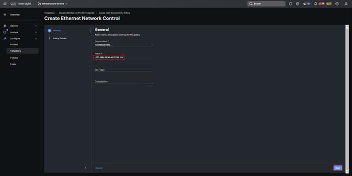
Step 73. Enable Cisco Discovery Protocol and both Enable Transmit and Enable Receive under LLDP. Click Create.
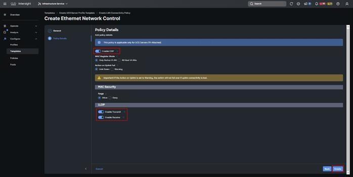
Step 74. Click Select Policy under Ethernet QoS and click Create New.
Note: The Ethernet QoS policy is used to enable jumbo maximum transmission units (MTUs) for all the vNICs. A single policy will be created and reused for all the vNICs.
Step 75. Verify the correct organization is selected from the drop-down list and provide a name for the policy (for example, FS-L151-DMZ-K8-GEN5-NODEQOS_Pol).
Step 76. Click Next.
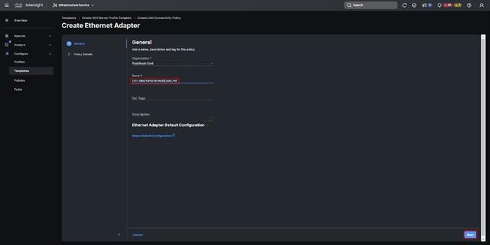
Step 77. Change the MTU Bytes value to 9000. Click Create.
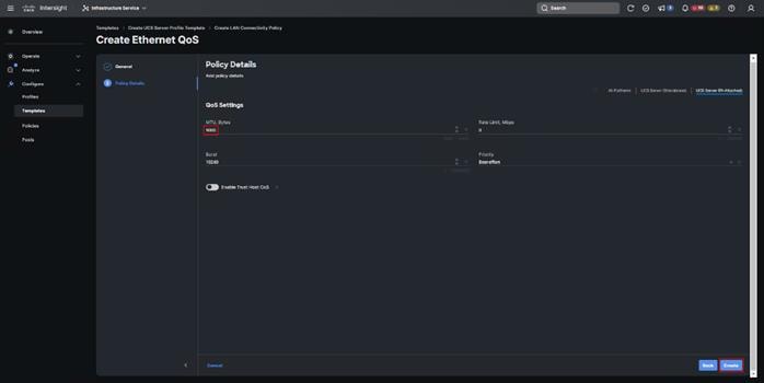
Step 78. Click Select Policy under Ethernet Adapter and then click Create New.
Note: The ethernet adapter policy is used to set the interrupts and the send and receive queues. The values are set according to the best-practices guidance for the operating system in use. Cisco Intersight provides default VMware Ethernet Adapter policy for typical VMware deployments. Optionally, you can configure a tweaked ethernet adapter policy for additional hardware receive queues handled by multiple CPUs in scenarios where there is a lot of vMotion traffic and multiple flows. In this deployment, a modified ethernet adapter policy, L151-DMZ-GEN5-M7-EthAdapt-VMware-HiTraffic, is created and attached to the VDS0-A and VDS0-B interfaces which handle vMotion.
Table 10. Ethernet Adapter Policy association to vNICs
| Policy Name |
vNICS |
| L151-DMZ-GEN5-M7-EthAdapt-VMware |
vSwitch0-A, vSwitch0-B |
| L151-DMZ-GEN5-M7-EthAdapt-VMware-HiTraffic |
VDS0-A, VDS0-B, |
Step 79. Verify the correct organization is selected from the drop-down list and provide a name for the policy (for example, L151-GEN5-M7-DMZ-EthAdapt-VMware).
Step 80. Click Select Default Configuration under Ethernet Adapter Default Configuration.
Step 81. From the list, select VMware. Click Next.
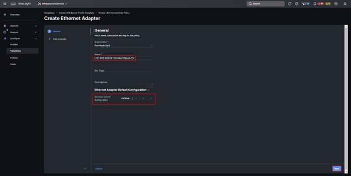
Step 82. For the FS-L151-DMZ-EthAdapt-VMware policy, click Create and skip the rest of the steps in this section.
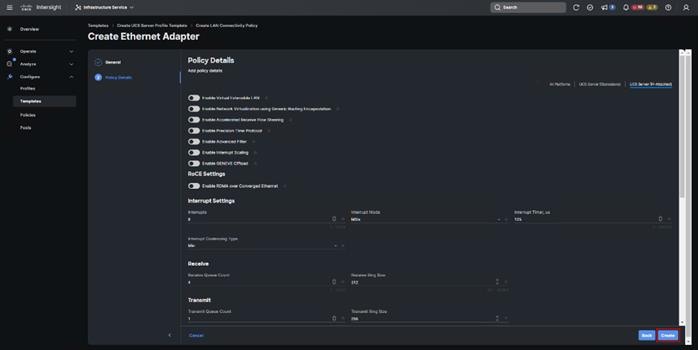
For the optional FS-L151-DMZ-EthAdapt-VMware-HiTraffic policy used for VDS interfaces, make the following modifications to the policy:
● Increase Interrupts to 11
● Increase Receive Queue Count to 8
● Increase Completion Queue Count to 9
● Enable Receive Side Scaling
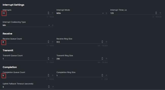

Step 83. Click Create.
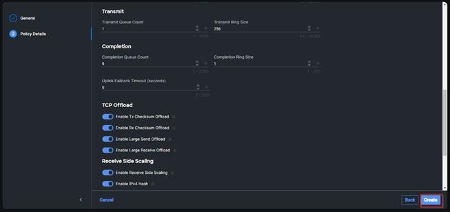
Step 84. Click Create to finish creating the vNIC.
Step 85. Repeat the vNIC creation steps for the rest of vNICs. Verify all four vNICs were successfully created. Click Create.
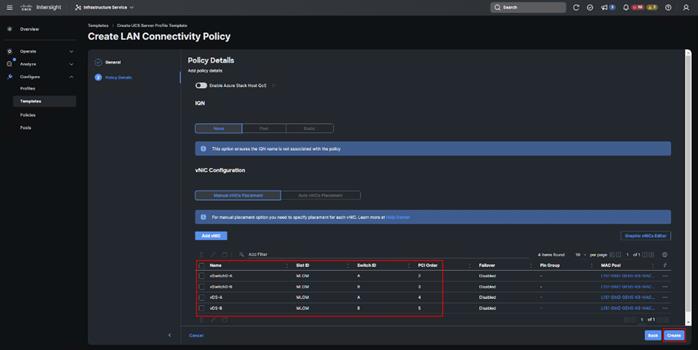
Step 86. Click Select Policy next to SAN Connectivity and then click Create New.
Note: A SAN connectivity policy determines the network storage resources and the connections between the server and the storage device on the network. This policy enables you to configure the vHBAs that the servers use to communicate with the SAN.
Table 11. vHBA for boot from FC SAN
| vNIC/vHBA Name |
Slot |
Switch ID |
PCI Order |
| vHBA-A |
MLOM |
A |
0 |
| vHBA-B |
MLOM |
B |
1 |
Step 87. Verify the correct organization is selected from the drop-down list and provide a name for the policy (for example, L151-DMZ-GEN5-SAN-CONN_Pol).
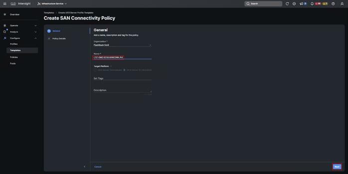
Step 88. Select Manual vHBAs Placement.
Step 89. Select Pool under WWNN.
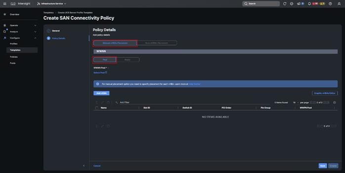
Note: The WWNN address pools have not been defined yet therefore a new WWNN address pool has to be defined.
Step 90. Click Select Pool under WWNN Pool and then click Create New.
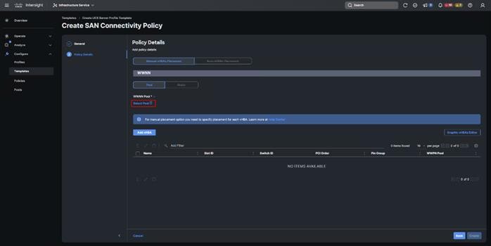
Step 91. Verify the correct organization is selected from the drop-down list and provide a name for the policy (for example, L151-DMZ-K8-GEN5-WWN-Pool).
Step 92. Click Next.
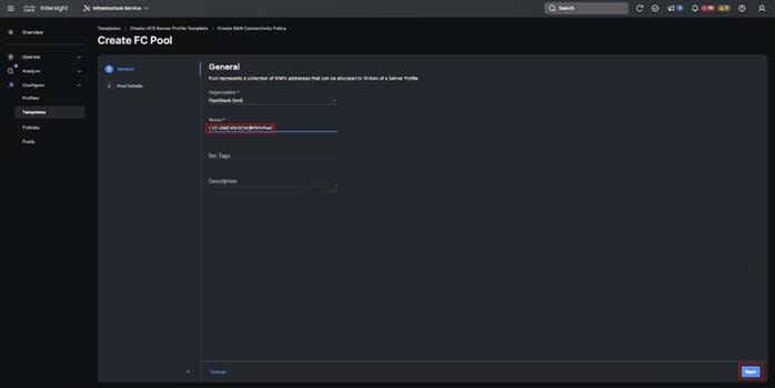
Step 93. Provide the starting WWNN block address and the size of the pool. Click Create.
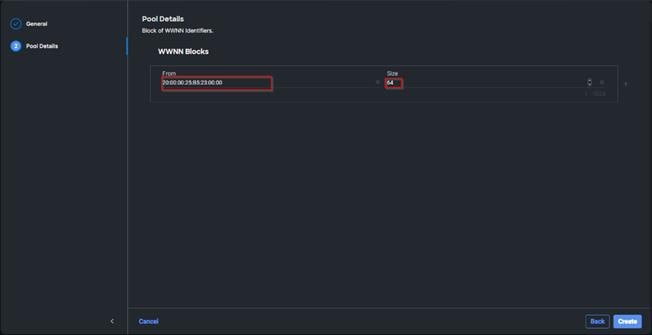
Note: As a best practice, additional information should always be coded into the WWNN address pool for troubleshooting. For example, in the address 20:00:00:25:B5:23:00:00, 23 is the rack ID.
Step 94. Click Add vHBA.

Step 95. Enter vHBA-A for the Name and select fc-initiator from the drop-down list.
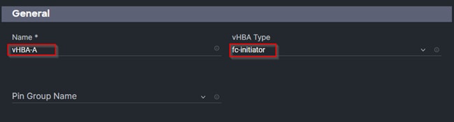
Note: The WWPN address pool has not been defined yet therefore a WWPN address pool for Fabric A will be defined.
Step 96. Click Select Pool under WWPN Address Pool and then click Create New.
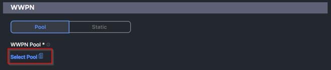
Step 97. Verify the correct organization is selected from the drop-down list and provide a name for the policy (for example, L151-DMZ-K8-GEN5-WWPN-Pool-A).
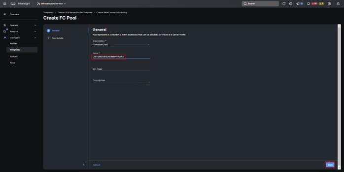
Step 98. Provide the starting WWPN block address for SAN A and the size. Click Create.
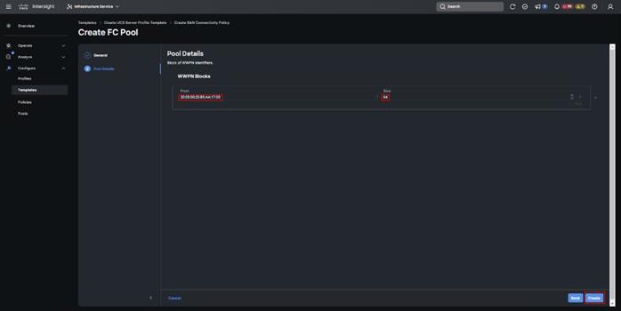
Step 99. Provide the Switch ID (for example, A) and PCI Order (for example, 0) from Table 11.
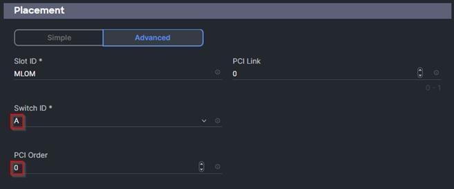
Step 100. Click Select Policy under Fibre Channel Network and then click Create New.
Note: A Fibre Channel network policy governs the VSAN configuration for the virtual interfaces. In this deployment, VSAN 100 will be used for vHBA-A and VSAN 101 will be used for vHBA-B.
Step 101. Verify the correct organization is selected from the drop-down list and provide a name for the policy (for example, L151-DMZ-GEN5-K8-FCN-A_Pol). Click Next.
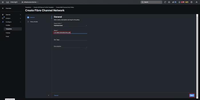
Step 102. For the scope, select UCS Server (FI-Attached).
Step 103. Under VSAN ID, provide the VSAN information (for example, 100).
Step 104. Click Create.
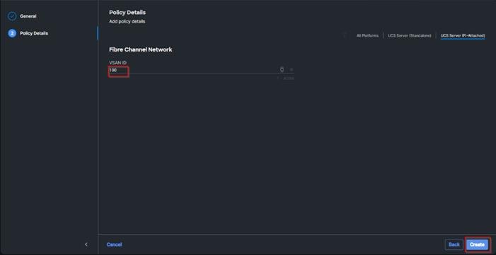
Step 105. Click Select Policy under Fibre Channel QoS and then click Create New.
Note: The Fibre Channel QoS policy assigns a system class to the outgoing traffic for a vHBA. This system class determines the quality of service for the outgoing traffic. The Fibre Channel QoS policy used in this deployment uses default values and will be shared by all vHBAs.
Step 106. Verify the correct organization is selected from the drop-down list and provide a name for the policy (for example, L151-DMZ-K8-GEN5-FCQOS_Pol). Click Next.
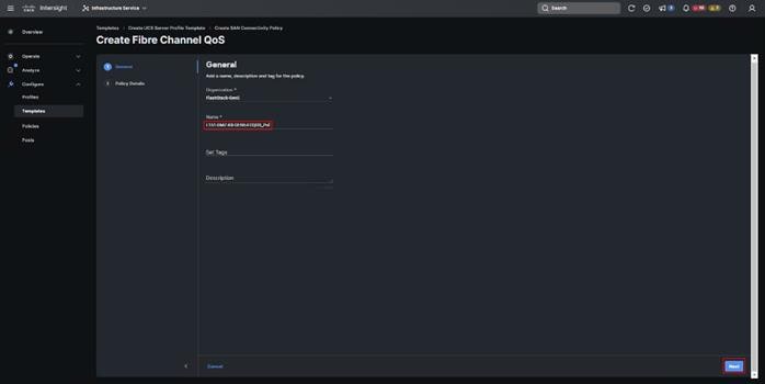
Step 107. For the scope, select UCS Server (FI-Attached).
Note: Do not change the default values on the Policy Details screen.
Step 108. Click Create.
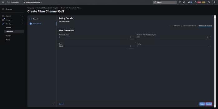
Step 109. Click Select Policy under Fibre Channel Adapter and then click Create New.
Note: A Fibre Channel adapter policy governs the host-side behavior of the adapter, including the way that the adapter handles traffic. This validation uses the default values for the adapter policy, and the policy will be shared by all the vHBAs.
Step 110. Verify the correct organization is selected from the drop-down list and provide a name for the policy (for example, L151-DMZ-K8-GEN5-FC-Adapter_Pol).
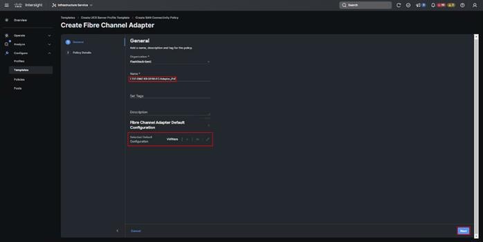
Step 111. For the scope, select UCS Server (FI-Attached).
Note: Do not change the default values on the Policy Details screen.
Step 112. Click Create.
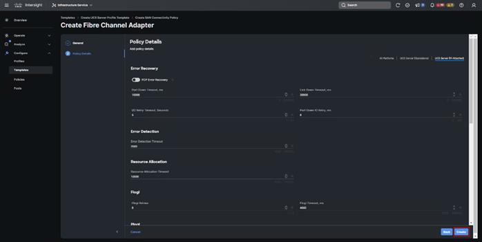
Step 113. Click Add to create vHBA-A.
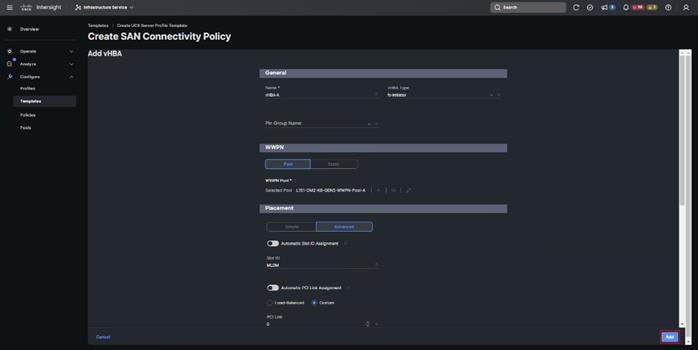
Step 114. Create the vHBA-B using the same steps from above using the pools and Fibre Channel Network policy for SAN-B.
Step 115. Verify both vHBAs are added to the SAN connectivity policy.
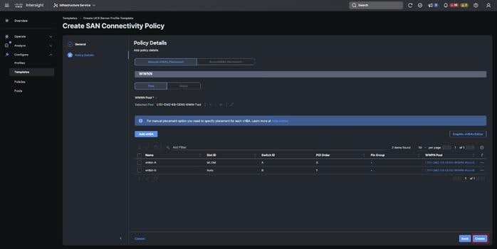
Step 116. When the LAN connectivity policy and SAN connectivity policy are created and assigned, click Next to move to the Summary screen.
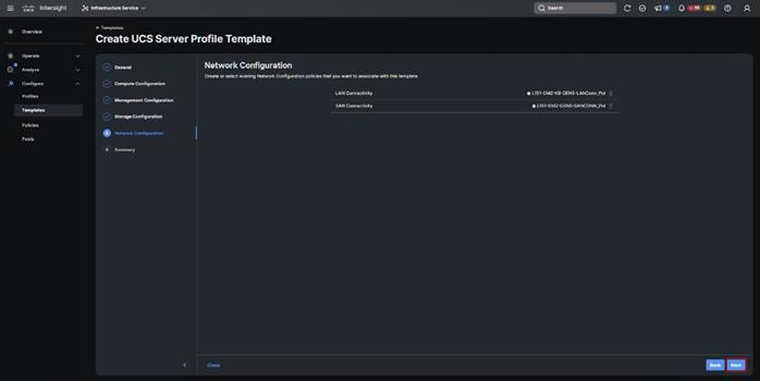
Step 117. From the Server profile template Summary screen, click Derive Profiles.
Note: This action can also be performed later by navigating to Templates, clicking “…” next to the template name and selecting Derive Profiles.
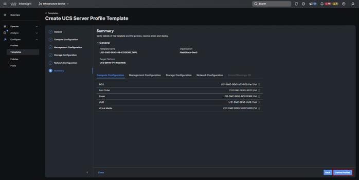
Step 118. Under the Server Assignment, select Assign Now and select Cisco UCS X210c M6 Nodes. You can select one or more servers depending on the number of profiles to be deployed. Click Next.
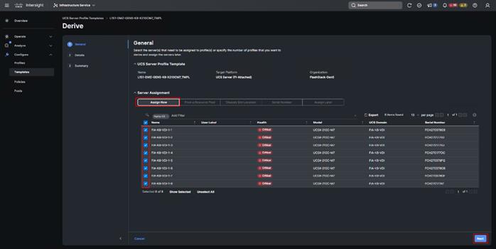
Cisco Intersight will fill the default information for the number of servers selected.
Step 119. Adjust the Prefix and number as needed. Click Next.
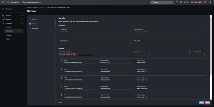
Step 120. Verify the information and click Derive to create the Server Profiles.
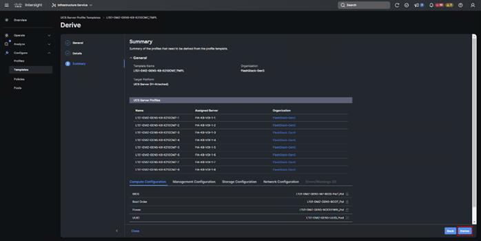
Virtual Port Channel (vPC) Summary for Data and Storage Network
In the Cisco Nexus 93180YC-FX switch topology, a single vPC feature is enabled to provide HA, faster convergence in the event of a failure, and greater throughput. Cisco Nexus 93180YC-FX vPC configurations with the vPC domains and corresponding vPC names and IDs for Oracle Database Servers is listed in Table 12.
| vPC Domain |
vPC Name |
vPC ID |
| 70 |
Peer-Link |
1 |
| 70 |
vPC Port-Channel to FI-A |
30 |
| 70 |
vPC Port-Channel to FI-B |
31 |
As listed in Table 12, a single vPC domain with Domain ID 70 is created across two Cisco Nexus 93180YC-FX member switches to define vPC members to carry specific VLAN network traffic. In this topology, a total number of 3 vPCs were defined:
● vPC ID 1 is defined as Peer link communication between two Nexus switches in Fabric A and B.
● vPC IDs 30 and 31 are defined for traffic from Cisco UCS fabric interconnects.
Cisco Nexus 93180YC-FX Switch Cabling Details
The following tables list the cabling information.
Table 13. Cisco Nexus 93180YC-FX-A Cabling Information
| Local Device |
Local Port |
Connection |
Remote Device |
Remote Port |
| Cisco Nexus 93180YC-FX Switch A |
Eth1/51 |
100Gbe |
Cisco UCS fabric interconnect A |
Eth1/29 |
| Eth1/52 |
100Gbe |
Cisco UCS fabric interconnect B |
Eth1/29 |
|
| Eth1/25 |
25Gbe |
FlashArray//X 50 R4 CT0 |
Eth1/2 |
|
| Eth1/26 |
25Gbe |
FlashArray//X 50 R4 CT1 |
Eth1/3 |
|
| Eth1/1 |
10Gbe |
Cisco Nexus 93180YC-FX B |
Eth1/1 |
|
| Eth1/2 |
10Gbe |
Cisco Nexus 93180YC-FX B |
Eth1/2 |
|
| Eth1/3 |
10Gbe |
Cisco Nexus 93180YC-FX B |
Eth1/3 |
|
| Eth1/4 |
10Gbe |
Cisco Nexus 93180YC-FX B |
Eth1/4 |
|
| MGMT0 |
1Gbe |
Gbe management switch |
Any |
Table 14. Cisco Nexus 93180YC-FX-B Cabling Information
| Local Device |
Local Port |
Connection |
Remote Device |
Remote Port |
| Cisco Nexus 93180YC-FX Switch B |
Eth1/51 |
100Gbe |
Cisco UCS fabric interconnect A |
Eth1/30 |
| Eth1/52 |
100Gbe |
Cisco UCS fabric interconnect B |
Eth1/30 |
|
| Eth1/25 |
25Gbe |
FlashArray//X 50 R4 CT0 |
Eth1/2 |
|
| Eth1/26 |
25Gbe |
FlashArray//X 50 R4 CT1 |
Eth1/3 |
|
| Eth1/1 |
10Gbe |
Cisco Nexus 93180YC-FX A |
Eth1/1 |
|
| Eth1/2 |
10Gbe |
Cisco Nexus 93180YC-FX A |
Eth1/2 |
|
| Eth1/3 |
10Gbe |
Cisco Nexus 93180YC-FX A |
Eth1/3 |
|
| Eth1/4 |
10Gbe |
Cisco Nexus 93180YC-FX A |
Eth1/4 |
|
| MGMT0 |
1Gbe |
Gbe management switch |
Any |
Cisco UCS Fabric Interconnect 6536 Cabling
The following tables list the Cisco UCS FI 6536 cabling information.
Table 15. Cisco UCS Fabric Interconnect (FI) A Cabling Information
| Local Device |
Local Port |
Connection |
Remote Device |
Remote Port |
| Cisco UCS FI-6536-A |
FC 1/35/1 |
32G FC |
Cisco MDS 9132T 32-Gb-A |
FC 1/15 |
| FC 1/35/2 |
32G FC |
Cisco MDS 9132T 32-Gb-A |
FC 1/16 |
|
| Eth1/3-6 |
100Gbe |
UCS 9508 Chassis IFM-A Chassis 1 |
Intelligent Fabric Module 1 Port1-4 |
|
| Eth1/29 |
100Gbe |
Cisco Nexus 93180YC-FX Switch A |
Eth1/51 |
|
| Eth1/30 |
100Gbe |
Cisco Nexus 93180YC-FX Switch B |
Eth1/52 |
|
| Mgmt 0 |
1Gbe |
Management Switch |
Any |
|
| L1 |
1Gbe |
Cisco UCS FI - A |
L1 |
|
| L2 |
1Gbe |
Cisco UCS FI - B |
L2 |
Table 16. Cisco UCS Fabric Interconnect (FI) B Cabling Information
| Local Device |
Local Port |
Connection |
Remote Device |
Remote Port |
| Cisco UCS FI-6536-B |
FC 1/35/1 |
32Gb FC |
Cisco MDS 9132T 32-Gb-B |
FC 1/15 |
| FC 1/35/2 |
32Gb FC |
Cisco MDS 9132T 32-Gb-B |
FC 1/16 |
|
| Eth1/3-6 |
100Gbe |
UCS 9508 Chassis IFM-B Chassis 1 |
Intelligent Fabric Module 1 Port1-4 |
|
| Eth1/29 |
100Gbe |
Cisco Nexus 93180YC-FX Switch A |
Eth1/52 |
|
| Eth1/30 |
100Gbe |
Cisco Nexus 93180YC-FX Switch B |
Eth1/51 |
|
| Mgmt 0 |
1Gbe |
Management Switch |
Any |
|
| L1 |
1Gbe |
Cisco UCS FI - A |
L1 |
|
| L2 |
1Gbe |
Cisco UCS FI - B |
L2 |
Procedure 1. Create vPC Peer-Link Between the Two Cisco Nexus Switches
Step 1. Log in as “admin” user into the Cisco Nexus Switch A.
Note: For vPC 1 as Peer-link, we used interfaces 1-4 for Peer-Link. You may choose the appropriate number of ports for your needs.
Step 2. Create the necessary port channels between devices by running these commands on both Cisco Nexus switches:
config terminal
feature vpc
feature lacp
vpc domain 50
peer-keepalive destination 173.37.52.104 source 173.37.52.103
exit
interface port-channel 10
description VPC peer-link
switchport mode trunk
switchport trunk allowed VLAN 1,70-76
spanning-tree port type network
vpc peer-link
interface Ethernet1/1
description VPC to K23-N9K-A
switchport mode trunk
switchport trunk allowed vlan 1,70-76,132
channel-group 10 mode active
no shutdown
exit
interface Ethernet1/2
description VPC to K23-N9K-A
switchport mode trunk
switchport trunk allowed vlan 1,70-76,132
channel-group 10 mode active
no shutdown
exit
interface Ethernet1/3
description VPC to K23-N9K-A
switchport mode trunk
switchport trunk allowed vlan 1,70-76,132
channel-group 10 mode active
no shutdown
exit
interface Ethernet1/4
description VPC to K23-N9K-A
switchport mode trunk
switchport trunk allowed vlan 1,70-76,132
channel-group 10 mode active
no shutdown
exit
copy running-config startup-config
Step 3. Log in as admin user into the Nexus Switch B and repeat the above steps to configure second Cisco Nexus switch.
Step 4. Make sure to change the peer-keepalive destination and source IP address appropriately for Cisco Nexus Switch B.
Procedure 2. Create vPC Configuration Between Cisco Nexus 93180YC-FX and Cisco Fabric Interconnects
Create and configure vPC 11 and 12 for the data network between the Cisco Nexus switches and fabric interconnects.
Note: Create the necessary port channels between devices, by running the following commands on both Cisco Nexus switches.
Step 1. Log in as admin user into Cisco Nexus Switch A and enter the following:
config terminal
interface port-channel11
description FI-A-Uplink
switchport mode trunk
switchport trunk allowed VLAN 1,70-76
spanning-tree port type edge trunk
vpc 11
no shutdown
exit
interface port-channel12
description FI-B-Uplink
switchport mode trunk
switchport trunk allowed VLAN 1,70-76
spanning-tree port type edge trunk
vpc 12
no shutdown
exit
interface Ethernet1/51
description FI-A-Uplink
switch mode trunk
switchport trunk allowed vlan 1,70-76
spanning-tree port type edge trunk
mtu 9216
channel-group 11 mode active
no shutdown
exit
interface Ethernet1/52
description FI-B-Uplink
switch mode trunk
switchport trunk allowed vlan 1,70-76
spanning-tree port type edge trunk
mtu 9216
channel-group 12 mode active
no shutdown
exit
copy running-config startup-config
Step 2. Log in as admin user into the Nexus Switch B and complete the following for the second switch configuration:
config Terminal
interface port-channel11
description FI-A-Uplink
switchport mode trunk
switchport trunk allowed VLAN 1,70-76
spanning-tree port type edge trunk
vpc 11
no shutdown
exit
interface port-channel12
description FI-B-Uplink
switchport mode trunk
switchport trunk allowed VLAN 1,70-76
spanning-tree port type edge trunk
vpc 12
no shutdown
exit
interface Ethernet1/51
description FI-A-Uplink
switch mode trunk
switchport trunk allowed vlan 1,70-76
spanning-tree port type edge trunk
mtu 9216
channel-group 11 mode active
no shutdown
exit
interface Ethernet1/52
description FI-B-Uplink
switch mode trunk
switchport trunk allowed vlan 1,70-76
spanning-tree port type edge trunk
mtu 9216
channel-group 12 mode active
no shutdown
exit
copy running-config startup-config
Verify vPC Status is up on both Cisco Nexus Switches
Figure 23 shows the verification of the vPC status on both Cisco Nexus Switches.
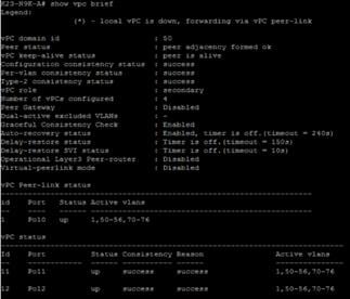
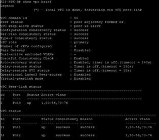
Cisco MDS 9132T 32-Gb FC Switch Configuration
Figure 18 illustrates the cable connectivity between the Cisco MDS 9132T 32-Gb switch and the Cisco 6536 Fabric Interconnects and Pure Storage FlashArray//50 storage.
Table 17. Cisco MDS 9132T-A Cabling Information
| Local Device |
Local Port |
Connection |
Remote Device |
Remote Port |
| Cisco MDS 9132T-A
|
FC1/13 |
32Gb FC |
Pure Storage FlashArray//50 R4 CT 0 |
CT0.FC4 |
| FC1/14 |
32Gb FC |
Pure Storage FlashArray//50 R4 CT 1 |
CT1.FC4 |
|
| FC1/15 |
32Gb FC |
Cisco 6536 Fabric Interconnect-A |
FC1/35/1 |
|
| FC1/16 |
32Gb FC |
Cisco 6536 Fabric Interconnect-A |
FC1/35/2 |
Table 18. Cisco MDS 9132T-B Cabling Information
| Local Device |
Local Port |
Connection |
Remote Device |
Remote Port |
| Cisco MDS 9132T-B
|
FC1/13 |
32Gb FC |
Pure Storage FlashArray//50 R4 CT 0 |
CT0.FC5 |
| FC1/14 |
32Gb FC |
Pure Storage FlashArray//50 R4 CT 1 |
CT1.FC5 |
|
| FC1/15 |
32Gb FC |
Cisco 6536 Fabric Interconnect-B |
FC1/35/1 |
|
| FC1/16 |
32Gb FC |
Cisco 6536 Fabric Interconnect-B |
FC1/35/2 |
Procedure 1. Configure Features and name for MDS Switch A and MDS Switch B
Step 1. Log in as admin user into MDS Switch A:
config terminal
feature npiv
feature telnet
switchname L151K5-MDS-C9132T-A
copy running-config startup-config
Step 2. Log in as admin user into MDS Switch B. Repeat step 1 on MDS Switch B.
Procedure 2. Configure VSANs for MDS Switch A and MDS Switch B
Step 1. Log in as admin user into MDS Switch A. Create VSAN 100 for Storage Traffic:
config terminal
VSAN database
vsan 100
exit
zone smart-zoning enable vsan 100
vsan database
vsan 100 interface fc 1/13-16
exit
interface fc 1/13-16
switchport trunk allowed vsan 100
switchport trunk mode off
port-license acquire
no shutdown
exit
copy running-config startup-config
Step 2. Log in as admin user into MDS Switch B. Create VSAN 101 for Storage Traffic:
config terminal
VSAN database
vsan 101
exit
zone smart-zoning enable vsan 101
vsan database
vsan 101 interface fc 1/13-16
exit
interface fc 1/13-16
switchport trunk allowed vsan 101
switchport trunk mode off
port-license acquire
no shutdown
exit
copy running-config startup-config
Procedure 3. Create and Configure Fiber Channel Zoning
This procedure sets up the Fibre Channel connections between the Cisco MDS 9132T 32-Gb switches, the Cisco UCS Fabric Interconnects, and the Pure Storage FlashArray systems.
Before you configure the zoning details, decide how many paths are needed for each LUN and extract the WWPN numbers for each of the HBAs from each server. We used 2 HBAs for each Server. One of the HBAs (HBA-A) is connected to MDS Switch-A and other HBAs (HBA-B) is connected to MDS Switch-B.
Step 1. Log into the Cisco Intersight portal as a user with account administrator role.
Step 2. From the Service Selector drop-down list, choose Infrastructure Service.
Step 3. Navigate to Configure > Pools. Filter WWPN type pools.
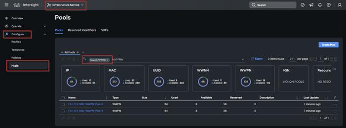
Step 4. Select the Usage tab and collect the WWPNs and profiles to which they are assigned.
Step 5. Connect to the Pure Storage System Health and go to the Connections tab and extract the WWPN of FC Ports connected to the Cisco MDS Switches from Array Ports section.
Note: We connected 4 FC ports from Pure Storage System to Cisco MDS Switches. FC ports CT0.FC0, CT1.FC0 are connected to MDS Switch-A and similarly FC ports CT1.FC2, CT0.FC2 are connected to MDS Switch-B.
Procedure 4. Create Device Aliases for Fiber Channel Zoning for SAN Boot Paths and Datapaths on Cisco MDS Switch A
Step 1. Log in as admin user and run the following commands from the global configuration mode:
configure terminal
device-alias mode enhanced
device-alias database
device-alias name Host-FCP-1-HBA0 pwwn 20:00:00:25:B5:AA:17:08
device-alias name Host-FCP-2-HBA0 pwwn 20:00:00:25:B5:AA:17:09
device-alias name Host-FCP-3-HBA0 pwwn 20:00:00:25:B5:AA:17:0A
device-alias name Host-FCP-4-HBA0 pwwn 20:00:00:25:B5:AA:17:0B
device-alias name Host-FCP-5-HBA0 pwwn 20:00:00:25:B5:AA:17:0C
device-alias name Host-FCP-6-HBA0 pwwn 20:00:00:25:B5:AA:17:0D
device-alias name Host-FCP-7-HBA0 pwwn 20:00:00:25:B5:AA:17:0E
device-alias name Host-FCP-8-HBA0 pwwn 20:00:00:25:B5:AA:17:0F
device-alias name X50R4-CT0-FC4 pwwn 52:4A:93:7A:CB:19:E9:04
device-alias name X50R4-CT1-FC4 pwwn 52:4A:93:7A:CB:19:E9:14
exit
device-alias commit
Procedure 5. Create Device Aliases for Fiber Channel Zoning for SAN Boot Paths and Datapaths on Cisco MDS Switch B
Step 1. Log in as admin user and run the following commands from the global configuration mode:
configure terminal
device-alias mode enhanced
device-alias database
device-alias name X50R4-CT0-FC5 pwwn 52:4A:93:7A:CB:19:E9:05
device-alias name X50R4-CT1-FC5 pwwn 52:4A:93:7A:CB:19:E9:15
device-alias name Host-FCP-1-HBA1 pwwn 20:00:00:25:B5:BB:17:08
device-alias name Host-FCP-2-HBA1 pwwn 20:00:00:25:B5:BB:17:09
device-alias name Host-FCP-3-HBA1 pwwn 20:00:00:25:B5:BB:17:0A
device-alias name Host-FCP-4-HBA1 pwwn 20:00:00:25:B5:BB:17:0B
device-alias name Host-FCP-5-HBA1 pwwn 20:00:00:25:B5:BB:17:0C
device-alias name Host-FCP-6-HBA1 pwwn 20:00:00:25:B5:BB:17:0D
device-alias name Host-FCP-7-HBA1 pwwn 20:00:00:25:B5:BB:17:0E
device-alias name Host-FCP-8-HBA1 pwwn 20:00:00:25:B5:BB:17:0F
exit
device-alias commit
Procedure 6. Create Fiber Channel Zoning for Cisco MDS Switch A for each Service Profile
Step 1. Log in as admin user and create the zone:
configure terminal
zone name FlashStack-Fabric-A vsan 100
member device-alias X50R4-CT0-FC4 target
member device-alias X50R4-CT1-FC4 target
member device-alias Host-FCP-1-HBA0 init
Step 2. After the zone for the Cisco UCS service profile has been created, create the zone set and add the created zones as members:
configure terminal
zoneset name VDI-Fabric-A vsan 100
member FlashStack-Fabric-A
Step 3. Activate the zone set by running following commands:
zoneset activate name VDI-Fabric-A vsan 100
exit
copy running-config startup-config
Procedure 7. Create Fiber Channel Zoning for Cisco MDS Switch B for each Service Profile
Step 1. Log in as admin user and create the zone as shown below:
configure terminal
zone name FlashStack-Fabric-B vsan 101
member device-alias X50R4-CT0-FC5 target
member device-alias X50R4-CT1-FC5 target
member device-alias Host-FCP-1-HBA1 init
member device-alias Host-FCP-2-HBA1 init
member device-alias Host-FCP-3-HBA1 init
member device-alias Host-FCP-4-HBA1 init
member device-alias Host-FCP-5-HBA1 init
member device-alias Host-FCP-6-HBA1 init
member device-alias Host-FCP-7-HBA1 init
Step 2. member device-alias Host-FCP-8-HBA1 init. After the zone for the Cisco UCS service profile has been created, create the zone set and add the necessary members:
zoneset name VDI-Fabric-B vsan 101
member FlashStack-Fabric-B
Step 3. Activate the zone set by running following commands:
zoneset activate name VDI-Fabric-B vsan 101
exit
copy running-config startup-config
Configure Pure Storage FlashArray//X50 R4
The design goal of the reference architecture is to best represent a real-world environment as closely as possible. The approach included the features of Cisco UCS to rapidly deploy stateless servers and use Pure Storage FlashArray’s boot LUNs to provision the ESXi on top of Cisco UCS. Zoning was performed on the Cisco MDS 9132T 32-Gb switches to enable the initiators discover the targets during boot process.
A Service Profile was created within Cisco UCS Manager to deploy the thirty-two servers quickly with a standard configuration. SAN boot volumes for these servers were hosted on the same Pure Storage FlashArray//X50 R4. Once the stateless servers were provisioned, following process was performed to enable rapid deployment of thirty-two blade servers.
Each Blade Server has dedicated single LUN to install operating system and all eight Blade Servers configured to boot from SAN. For this solution, we have installed vSphere ESXi 8.0 Update 2 Cisco Custom ISO on this LUNs to create solution.
Using logical servers that are disassociated from the physical hardware removes many limiting constraints around how servers are provisioned. Cisco UCS Service Profiles contain values for a server's property settings, including virtual network interface cards (vNICs), MAC addresses, boot policies, firmware policies, fabric connectivity, external management, and HA information. The service profiles represent all the attributes of a logical server in Cisco UCS model. By abstracting these settings from the physical server into a Cisco Service Profile, the Service Profile can then be deployed to any physical compute hardware within the Cisco UCS domain. Furthermore, Service Profiles can, at any time, be migrated from one physical server to another. Furthermore, Cisco is the only hardware provider to offer a truly unified management platform, with Cisco UCS Service Profiles and hardware abstraction capabilities extending to both blade and rack servers.
In addition to the service profiles, the use of Pure Storage’s FlashArray’s with SAN boot policy provides the following benefits:
● Scalability - Rapid deployment of new servers to the environment in a very few steps.
● Manageability - Enables seamless hardware maintenance and upgrades without any restrictions. This is a huge benefit in comparison to another appliance model like Exadata.
● Flexibility - Easy to repurpose physical servers for different applications and services as needed.
● Availability - Hardware failures are not impactful and critical. In rare case of a server failure, it is easier to associate the logical service profile to another healthy physical server to reduce the impact.
Configure Host, WWNs, and Volume Connectivity with FlashArray Management Tools
Procedure 1. Configure Host
Note: Before using a boot volume (LUN) by a Cisco UCS Blade Server, a host representing this blade server must be defined on Pure Storage FlashArray.
Step 1. Log into Pure Storage FlashArray Management interface.
Step 2. Click the Storage tab.
Step 3. Click the + sign in the Hosts section and select Create Host.
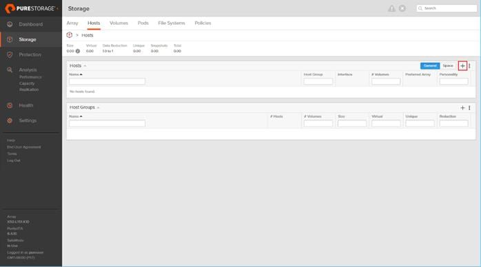
Step 4. Click Create Multiple to create a Host entries under the Hosts category.
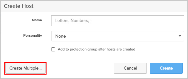
Step 5. Enter the required information and click Create.
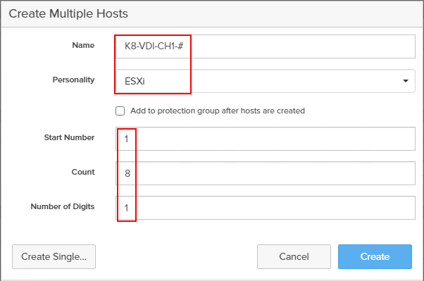
Step 6. Select one of the newly created hosts, in Host Ports section from the drop-down list select Configure WWNs.
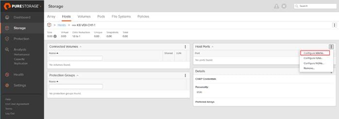
Step 7. Select the list of WWNs that belongs to the host in the next window and click Add.
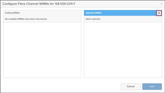
Note: Make sure the zoning has been setup to include the WWNs details of the initiators along with the target, without which the SAN boot will not work.
WWNs will appear only if the appropriate FC connections were made, and the zones were setup on the underlying FC switch.
Alternatively, the WWN can be added manually by clicking the + in the Selected WWNs section and manually inputting the blade’s WWNs.
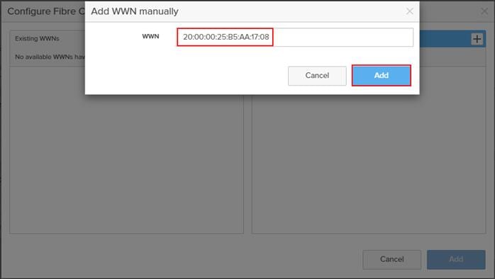
Procedure 2. Configure Volume Connectivity
Step 1. Click the Storage tab.
Step 2. Click the + sign in the Volumes section and click Create Volume.
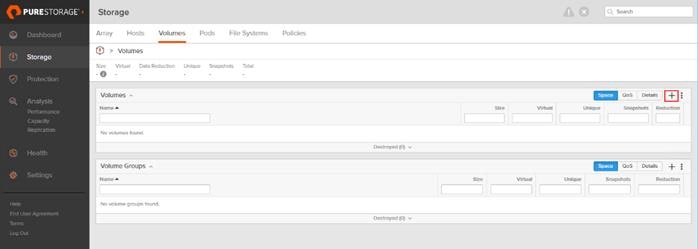
Step 3. Click Create Multiple to open Create Multiple Volumes wizard.
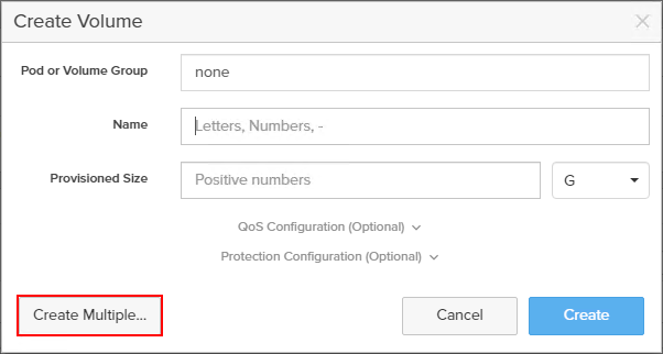
Step 4. Provide the common name of the volume, size, choose the size type (KB, MB, GB, TB, PB) and click Create to create volumes.
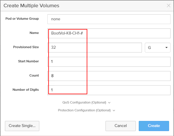
Step 5. Select one of the hosts and in Connected Volumes section from the drop-down list select Connect.
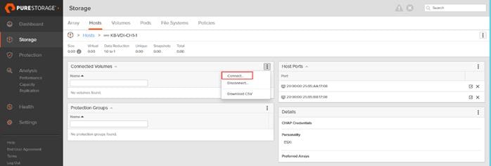
Step 6. In the Connect Volumes to Host wizard select the volume configured for ESXi installation, click Connect.
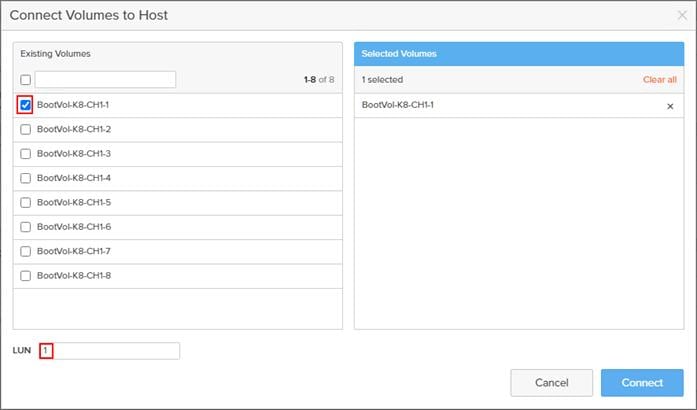
Note: Make sure the SAN Boot Volumes has the LUN ID “1” since this is important while configuring Boot from SAN. You will also configure the LUN ID as “1” when configuring Boot from SAN policy in Cisco UCS Manager.
Note: More LUNs can be connected by adding a connection to existing or new volume(s) to an existing node.
FA File services can be activated by Pure Storage Technical Services (Support). Please refer to FA File Services Support Matrix to verify that your hardware offers support for running File Services.
Currently all FA File services activations require Pure Storage Product Management approval. Customers can work with their local account representatives to obtain approval to activate File Services.
For additional information on FA File Services setup and configuration, see:
● FA File Services Quick Start Guide
● FA File Services Best Practices
Procedure 1. Create Virtual Interface(s)
The VIF provides high-availability network access across 2 physical Ethernet ports per array controller. Each VIF requires 2 physical ports per controller. Any physical ethernet port can be used with the restriction that any port that is in use by management services, a bond, or subnet configuration cannot be part of a VIF. For the maximum number of VIFs supported, please see the FA File Services Limits KB.
Note: VIFs are created by CLI over SSH, configured and enabled using the Management Console. An account with administrator privileges is required.
Step 1. Connect to the array using SSH.
Step 2. Run the following syntax to create the VIF on the array:
purenetwork create vif --subinterfacelist ct0.ethX,ct1.ethX,ct0.ethY,ct1.ethY <name of interface>
Procedure 2. Configure and Enable the Virtual Interface for File Services
Step 1. Connect to the array GUI.
Step 2. Navigate to Settings > Network.
Step 3. Locate the File VIF in the interface list and click the edit icon.
![]()
![]()
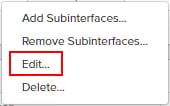
Step 4. In the Edit Interface dialog turn on the Enabled option, provide the IP Address, Netmask, and Gateway used by the interface. Click Save.
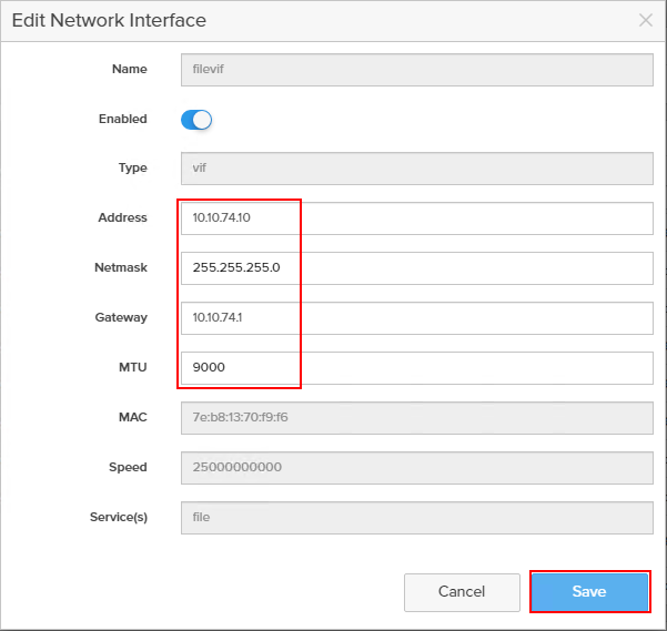
Step 5. Scroll to the bottom of the Network tab and click the edit icon for DNS Settings.
![]()
Step 6. In the Edit DNS Settings dialog, enter desired values for Domain and DNS server IPs. Click Save.
Note: More than one DNS server can be configured with the caveat that all DNS servers must have a record for Directory Service servers such as LDAP or Microsoft Active Directory.
Procedure 3. Create Active Directory Account for the Array
Step 1. Navigate to Settings > Access > Active Directory Accounts.
Step 2. To open the Create Dialog, click the + icon.
![]()
Enter the following information:
● Name = Array management name for this AD account
● Domain = AD domain name
● Computer Name = Computer Object name within AD
● User = Domain user that can create computer objects and join to the domain.
● Password = Users password for the above domain user
Step 3. Click Create to finalize AD account creation.
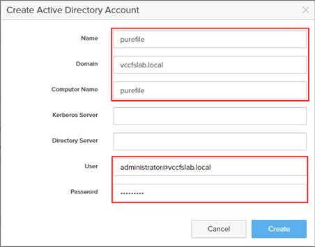
Procedure 4. Create a File System and Shared Directory
Step 1. Navigate to Storage > File Systems.
Step 2. Click the + icon.
![]()
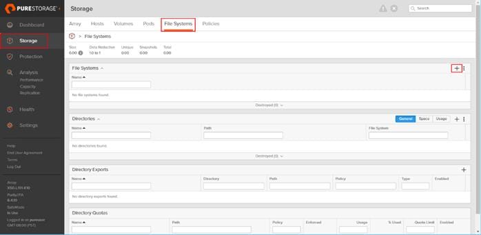
Step 3. In Create File System enter a file system name and click Create.
Step 4. Navigate to Storage > File Systems > Directories.
Step 5. Click the + icon.
![]()
Step 6. In Create Directory, enter Select a file system from the drop-down list, enter the desired management name of the directory, and enter the directory path in the file system. (for example, dir or /dir, for sub-level directories /dir/subdir or /dir/subdir/subdir1 can be used). Click Create.
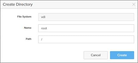
Note: Polices for exports/shares/snapshots can only be attached to managed directories at the file system root or 1 level deep (/ and /dir in the example above). Space and performance metrics can be seen at all levels of managed directories.
Step 7. Navigate to Storage > Policies.
Step 8. Click the + icon.
![]()
Step 9. In the Create Export Policy pop-up choose SMB from the Type drop-down list and enter a name for the policy. Click Create.
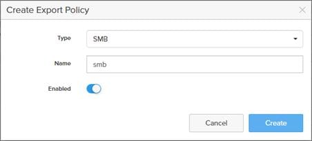
Step 10. Click Created Policy and click the + icon.
![]()
Step 11. Complete the Client filter for read-write access and click Add to complete the rule creation.
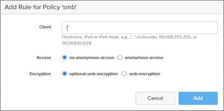
Step 12. Attach the export policy(s) to a managed directory. Click the + icon.
![]()
Step 13. Select a managed directory from the drop-down list, enter a share/export name, and click Create.
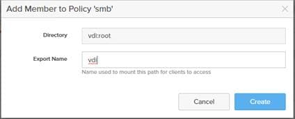
Step 14. Verify access to the created share from the Windows client.
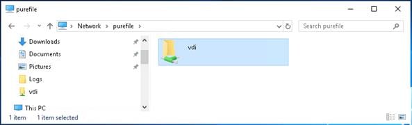
Install and Configure VMware ESXi 8.0
This section explains how to install VMware ESXi 8.0 U2 in an environment.
There are several methods to install ESXi in a VMware environment. These procedures focus on how to use the built-in keyboard, video, mouse (KVM) console and virtual media features in Cisco UCS Manager to map remote installation media to individual servers and install ESXi on boot logical unit number (LUN). Upon completion of steps outlined here, ESXi hosts will be booted from their corresponding SAN Boot LUNs.
Download Cisco Custom Image for VMware vSphere ESXi 8.0 U2
To download the Cisco Custom Image for VMware ESXi 8.0 U2, from the VMware vSphere Hypervisor 8.0 U2 page click the Custom ISOs tab.
Procedure 1. Install VMware vSphere ESXi 8.0 U2
Step 1. From the Service Selector drop-down list, select Infrastructure Service. Navigate to Operate > Servers.
Step 2. Right-click on … icon for the server being access and select Launch vKVM.
Step 3. Click Boot Device and then select vKVM Mapped vDVD.
![]()
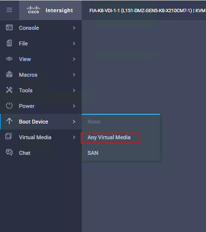
Step 4. Browse to the ESXi iso image file. Click Map Drive to mount the ESXi ISO image.
Step 5. Boot into ESXi installer and follow the prompts to complete installing VMware vSphere ESXi hypervisor.
Step 6. When selecting a storage device to install ESXi, select Remote LUN provisioned through Pure Storage Administrative console and access through FC connection.
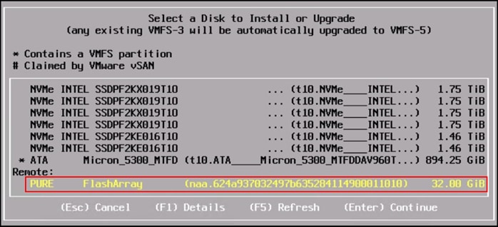
Procedure 2. Set Up Management Networking for ESXi Hosts
Adding a management network for each VMware host is necessary for managing the host and connection to vCenter Server. Select the IP address that can communicate with existing or new vCenter Server.
Step 1. After the server has finished rebooting, press F2 to enter in to configuration wizard for ESXi Hypervisor.
Step 2. Log in as root and enter the corresponding password.
Step 3. Select the Configure the Management Network option and press Enter.
Step 4. Select the VLAN (Optional) option and press Enter. Enter the VLAN In-Band management ID and press Enter.
Step 5. From the Configure Management Network menu, select IP Configuration and press Enter.
Step 6. Select the Set Static IP Address and Network Configuration option by using the space bar. Enter the IP address to manage the first ESXi host. Enter the subnet mask for the first ESXi host. Enter the default gateway for the first ESXi host. Press Enter to accept the changes to the IP configuration.
Step 7. IPv6 Configuration is set to automatic.
Step 8. Select the DNS Configuration option and press Enter.
Step 9. Enter the IP address of the primary and secondary DNS server. Enter Hostname
Step 10. Enter DNS Suffixes.
Note: Since the IP address is assigned manually, the DNS information must also be entered manually.
Note: The steps provided vary based on the configuration. Please make the necessary changes according to your configuration.
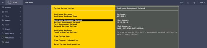
Procedure 3. Update Cisco VIC Drivers for ESXi
When ESXi is installed from Cisco Custom ISO, you might have to update the Cisco VIC drivers for VMware ESXi Hypervisor to match the current Cisco Hardware and Software Interoperability Matrix.
Note: Cisco Intersight incorporates an HCL check.
Note: If installing ESXi from non-Cisco ISO, you need to download and install IMM drivers separately. Run the following:
esxcli software component apply -d /vmfs/volumes/local-61/Cisco_UCS_Addon_ESXi_80U2_22380479_4.3.2-b_depot.zip
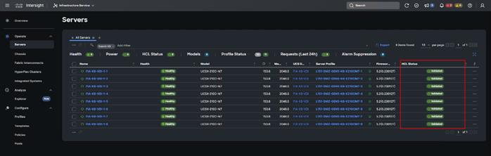
The VMware vSphere Client was configured to support the solution and testing environment as follows:
● Datacenter: FlashStack - Pure Storage FlashArray//X50 R4 with Cisco UCS
● Cluster: FlashStack-VDI - Single-session/Multi-session OS VDA workload
● Infrastructure : Infrastructure virtual machines (vCenter, Active Directory, DNS, DHCP, SQL Server, Citrix StoreFront Servers, Citrix Apps and Desktop Controllers, and other common services), Login VSI launcher infrastructure were connected using the same set of switches but hosted on separate VMware cluster managed by separate vCenter.
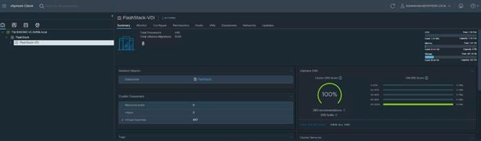
Procedure 1. Create and Prepare vSphere Cluster
Step 1. Create a vSphere host cluster.
Step 2. Configure NTP for all hosts in your vSphere cluster.
Procedure 2. Configure NTP
Step 1. On the vSphere Web Client home screen, select the Host object from the list on the left. From the Configure tab System area click Time Configuration.

Step 2. From Add Service drop-down list select Network Time protocol option.
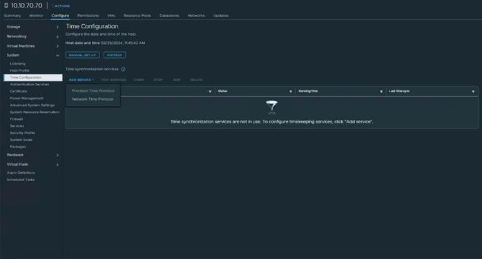
Step 3. Provide the IP addresses for the NTP servers in your environment. Click OK.
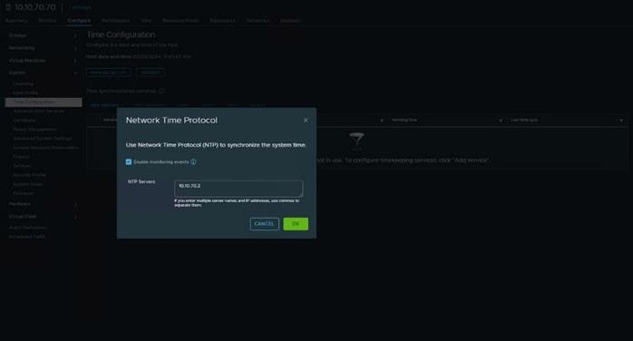
Step 4. Test the service configuration.
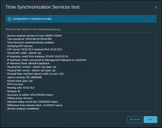
Step 5. Review the vCenter configuration.
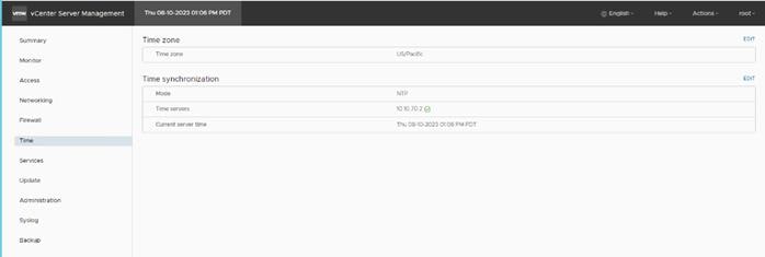
Note: SSH was also enabled to support data collection.
Create Distributed Switch
Procedure 1. Create a new vDS
Step 1. On the vSphere Web Client home screen, select the vCenter object from the list on the left. From the Inventory Lists area right-click on datacenter, then select Distributed Switch and click New Distributed Switch.
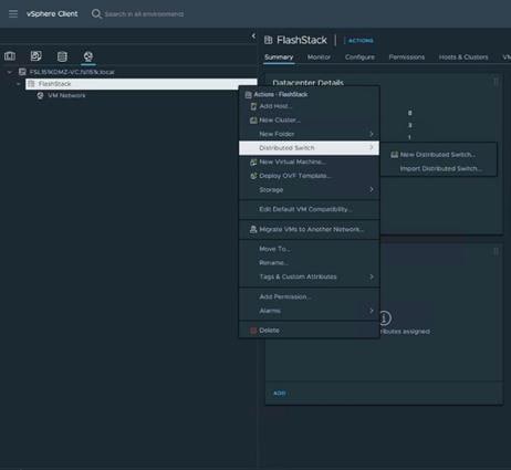
Step 2. Provide a name for the new distributed switch and select the location within the vCenter inventory where you would like to store the new vDS (a data center object or a folder). Click NEXT.
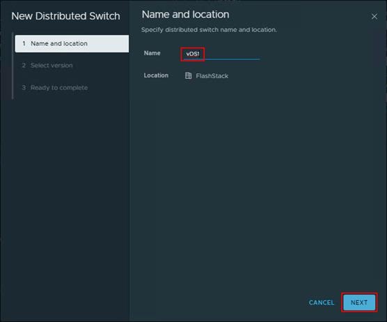
Step 3. Select the version of the vDS to create. Click NEXT.
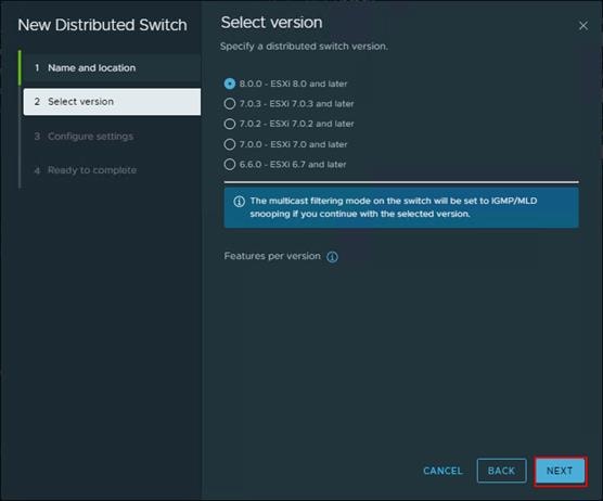
Step 4. Specify the Network Offloads compatibility as None, and number of uplink ports as 2. Uncheck the Create a default port group box. Click NEXT.
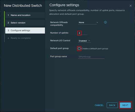
Step 5. Click Finish.
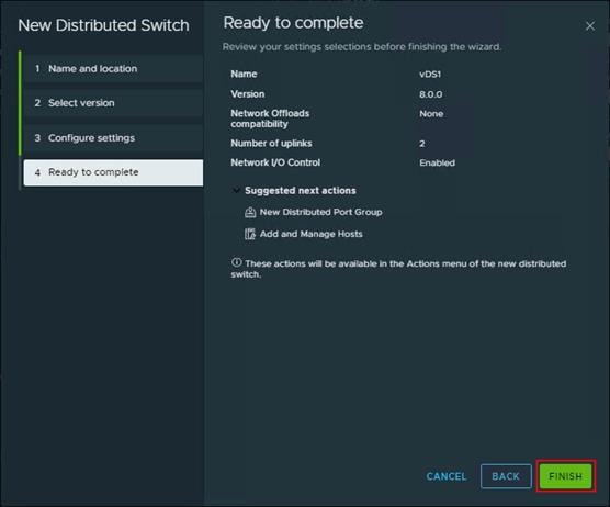
Step 6. Right-click the new distributed switch in the list of objects and select Settings > Edit Settings....
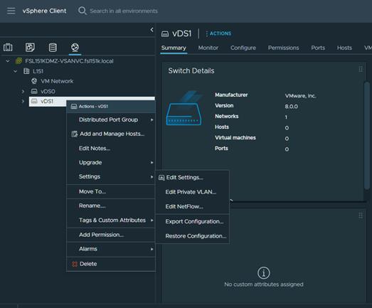
Step 7. In the Distributed Switch-Edit Settings dialog box Advanced tab, set the MTU to 9000, Discovery protocol to Link Layer Discovery Protocol and Operation to Both. Click OK.
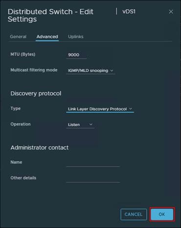
In Server Profiles, vmnic2 and vmnic3 are created for the use as vDS uplinks.
Step 8. Right-click the new distributed switch in the list of objects and select Add and Manage Hosts from the Actions menu.
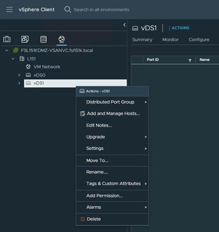
Step 9. Select the Add hosts button and click NEXT.
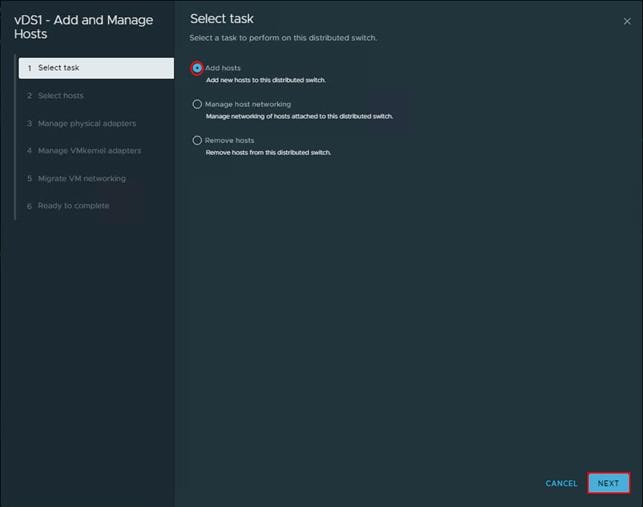
Step 10. From the list of the new hosts, check the boxes with the names of each ESXi host you would like to add to the VDS. Click NEXT.
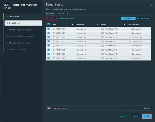
Step 11. In the next Manage physical adapters menu, click Adapters on all hosts and configure the adapters (in this case - vmnic2 and vmnic3) in an ESXi host as Uplink 1 and Uplink 2 for the vDS.
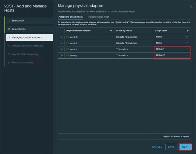
Step 12. In the next Manage VMkernel adapters and Migrate VM networking menus, click NEXT to continue.
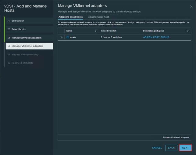
Step 13. In the next Manage VMkernel adapters and Migrate VM networking menus, click NEXT to continue.
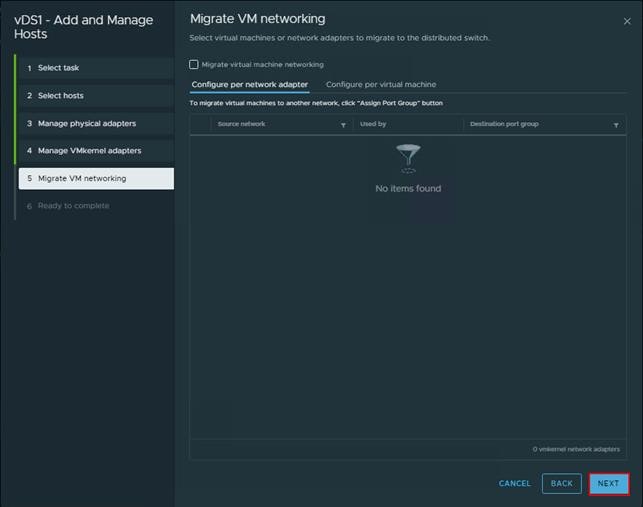
Step 14. Click FINISH.
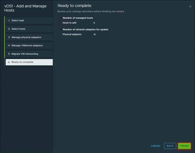
Procedure 2. Creating a Distributed Port Group for vMotion traffic
Step 1. Right-click Distributed switch and select Distributed Port Group click New Distributed Port Group.
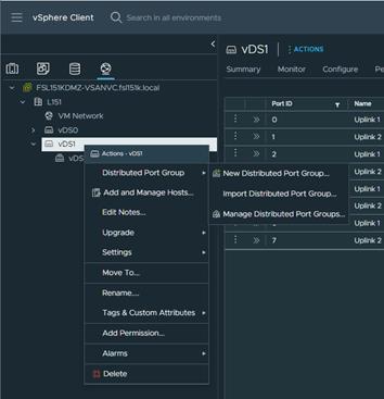
Step 2. On the New Distributed Port Group dialog box, enter a Name (for example vMotion), and click NEXT.
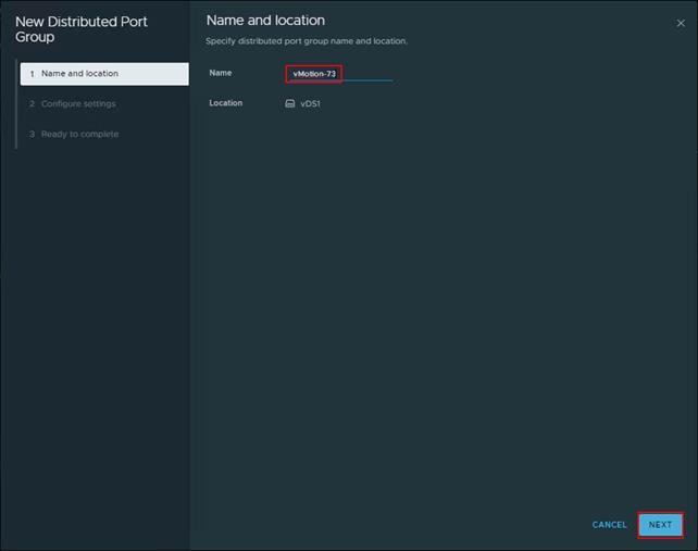
Step 3. In the VLAN type field, select VLAN, and set the VLAN ID to your VLAN (–for example 73). Check the box for Customize default policies configuration and click NEXT.
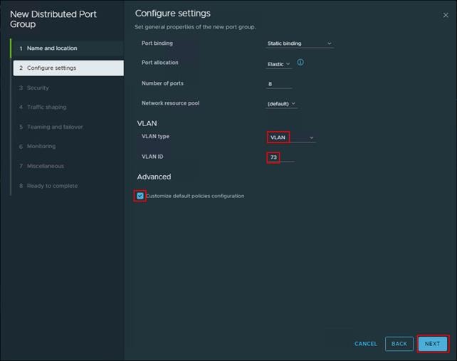
Step 4. On the Security dialog box, click NEXT.
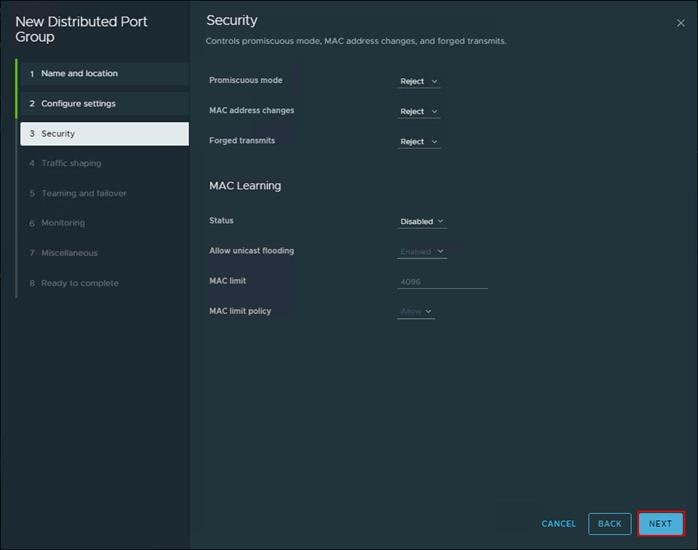
Step 5. On the Traffic shaping dialog box, click NEXT.
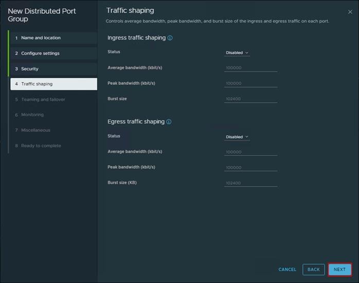
Step 6. In the Teaming and failover dialog box, select Uplink 1 as active uplink, and set Uplink 2 to be the standby uplink. Click NEXT.
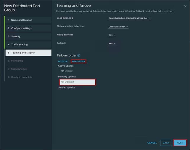
Step 7. In the Monitoring dialog box, set NetFlow to Disabled, and click NEXT.
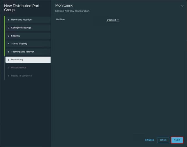
Step 8. In the Miscellaneous dialog box, set Block All Ports to No, and click NEXT.
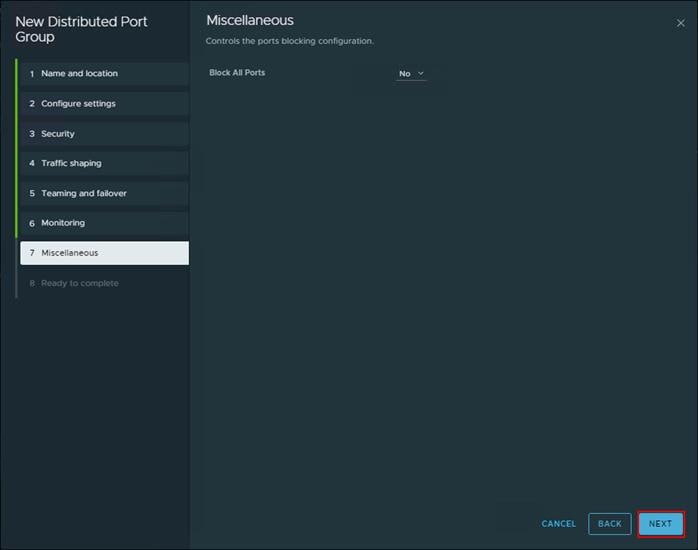
Step 9. In the Ready to complete dialog box, review all the changes, and click FINISH.
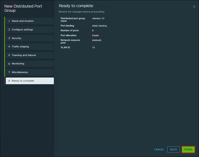
Step 10. Repeat the New Distributed Port Group … steps for any other required port groups.
Note: The completed configuration can be verified under the Distributed Switch Topology tab.
Procedure 3. Adding a VMkernel Adapters to Distributed Port Groups
Step 1. Right-click the distributed port group and select Add VMkernel Adapters….
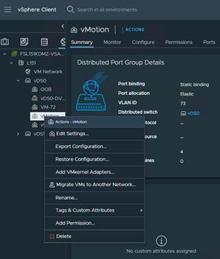
Step 2. Select Attached Hosts and click NEXT.
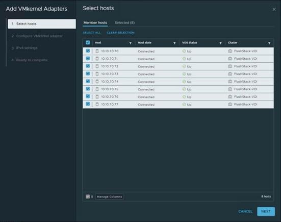
Step 3. Select service (for example vMotion) in Available services and click NEXT.
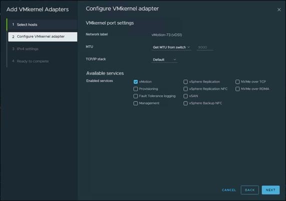
Step 4. Enter the Network Settings and Gateway details and click NEXT.
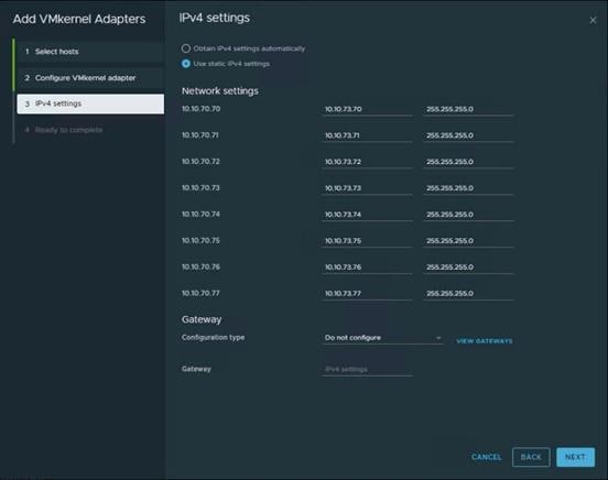
Step 5. Click FINISH.
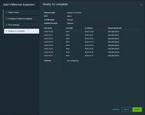
Step 6. Repeat the Add VMkernel Adapters… steps for any other required port groups.
The completed configuration can be verified under the Distributed Switch Topology tab.
Cisco Intersight Orchestration
Cisco Intersight Assist helps you add endpoint devices to Cisco Intersight. FlashStack environment includes multiple devices that do not connect directly with Cisco Intersight. Any device that is supported by Cisco Intersight, but does not connect directly with it, will need a connection mechanism. Cisco Intersight Assist provides that connection mechanism, and helps you add devices into Cisco Intersight.
Cisco Intersight Assist is available within the Cisco Intersight Virtual Appliance, which is distributed as a deployable virtual machine contained within an Open Virtual Appliance (OVA) file format. You can install the appliance on an ESXi server. For more information, see the Cisco Intersight Virtual Appliance Getting Started Guide.
After claiming Cisco Intersight Assist into Cisco Intersight, you can claim endpoint devices using the Claim Through Intersight Assist option.
Procedure 1. Configure Cisco Intersight Assist Virtual Appliance
Step 1. To install Cisco Intersight Assist from an Open Virtual Appliance (OVA) in your VMware FlashStack-Management Cluster, first download the latest release of the OVA here: https://software.cisco.com/download/home/286319499/type/286323047/release/1.0.9-630.
Step 2. To set up the DNS entries for the Cisco Intersight Assist hostname as specified under Before you Begin, go to: https://www.cisco.com/c/en/us/td/docs/unified_computing/Intersight/cisco-intersight-assist-getting-started-guide/m-installing-cisco-intersight-assist.html.
Step 3. From Hosts and Clusters in the VMware vCenter HTML5 client, right-click the FlashStack-Management cluster and click Deploy OVF Template.
Step 4. Specify a URL or browse to the intersight-appliance-installer-vsphere-1.0.9-630.ova file. Click NEXT.
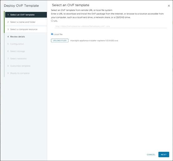
Step 5. Name the Cisco Intersight Assist VM and choose the location. Click NEXT.
Step 6. Select the FlashStack-Management cluster and click NEXT.
Step 7. Review details and click NEXT.
Step 8. Select a deployment configuration (Assist recommended) and click NEXT.
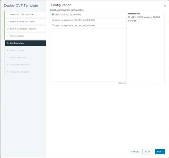
Step 9. Select the appropriate datastore for storage and select the Thin Provision virtual disk format. Click NEXT.
Step 10. Select IB-MGMT Network for the VM Network. Click NEXT.
Step 11. Fill in all values to customize the template. Click NEXT.
Step 12. Review the deployment information and click FINISH to deploy the appliance.
Step 13. Once the OVA deployment is complete, right-click the Cisco Intersight Assist VM and click Edit Settings.
Step 14. Expand CPU and adjust the Cores per Socket so that 2 Sockets are shown. Click OK.
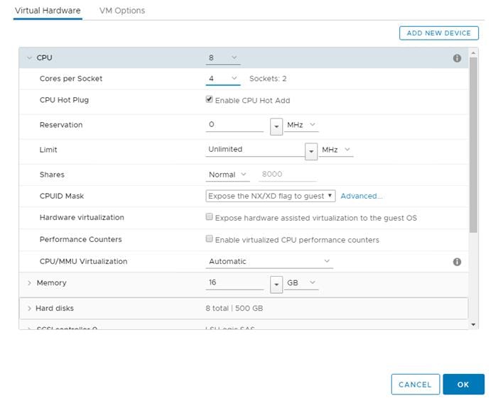
Step 15. Right-click the Cisco Intersight Assist VM and choose Open Remote Console.
Step 16. Power on the VM.
Step 17. When you see the login prompt, close the Remote Console, and connect to https://intersight-assist-fqdn.
It may take a few minutes for https://intersight-assist-fqdn to respond.
Step 18. Navigate the security prompts and select Install Assist. Click Start.
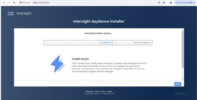
Step 19. Enable and configure proxy settings if required for the external connectivity.
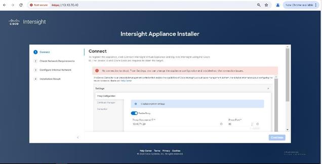
Step 20. From Cisco Intersight, click ADMIN > Targets. New Target. In the Select Target Type window, select Cisco Intersight Assist under Platform Services and click Start.
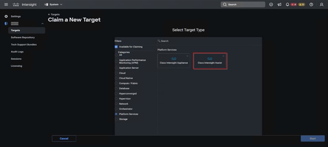
Step 21. Copy the Device ID and Claim Code shown in the Cisco Intersight Assist web interface.
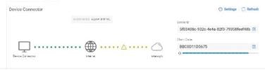
Step 22. Paste the Device ID and Claim Code to the Cisco Intersight Device Claim Direct Claim window in Cisco Intersight, then click Claim.
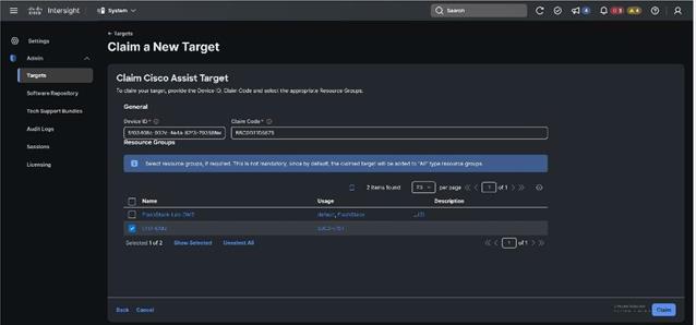
Step 23. In the Cisco Intersight Assist web interface, click Continue and follow the prompts.
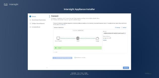
Note: The Cisco Intersight Assist software will now be downloaded and installed into the Cisco Intersight Assist VM. This can take up to an hour to complete.
Step 24. After a few minutes, Cisco Intersight Assist will appear in the Targets list.
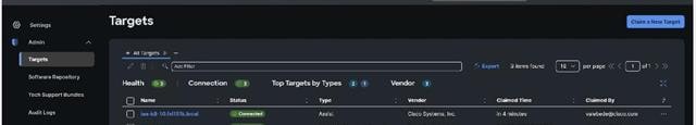
Procedure 2. Claim vCenter in Cisco Intersight
Step 1. To claim the vCenter, from Cisco Intersight, click ADMIN > Targets. Click Claim a New Target. In the Select Target Type window, select VMware vCenter under Hypervisor and click Start.
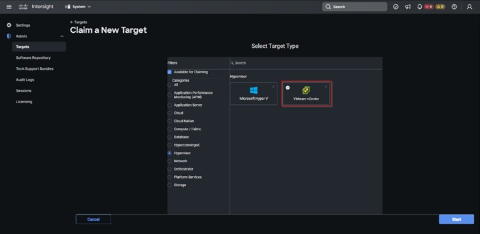
Step 2. In the VMware vCenter window, make sure the Intersight Assist is correctly selected, fill in the vCenter information, and click Claim.
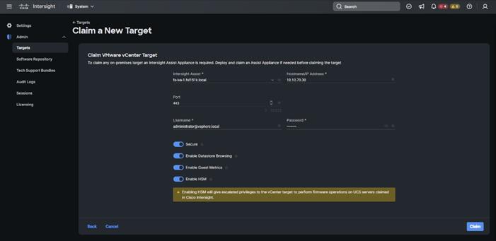
Step 3. After a few minutes, the VMware vCenter will appear in the Devices list. It also can be viewed by clicking Intersight Assist in the Devices list.
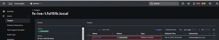
Step 4. Detailed information obtained from the vCenter can now be viewed by clicking Virtualization from the Infrastructure service > Operate menu.
Procedure 3. Claim FlashArray//X in Cisco Intersight
Step 1. Claiming a Pure Storage FlashArray also requires the use of an Intersight Assist virtual machine.
Step 2. To claim the vCenter, from Cisco Intersight, click ADMIN > Targets. Click Claim a New Target. In the Select Target Type window, select Pure Storage FlashArray under Storage and click Start.
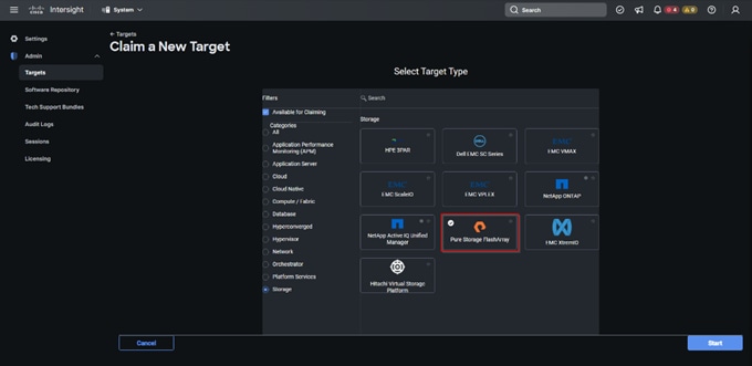
Step 3. Enter FlashArray Hostname/ IP address and credentials and click Claim.
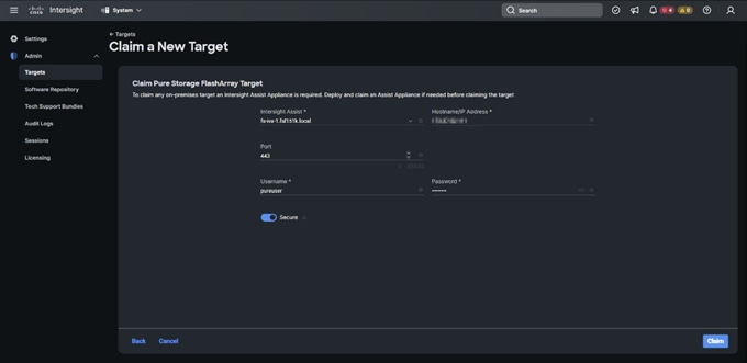
Step 4. After a few minutes, the array will appear in the Devices list. It also can be viewed by clicking Intersight Assist in the Devices list.
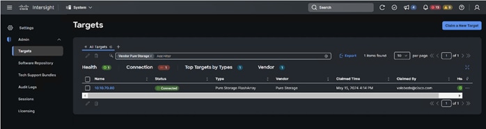
Step 5. Detailed information obtained from the vCenter can now be viewed by clicking Storage from the Infrastructure service > Operate menu.
Create all necessary DHCP scopes for the environment and set the Scope Options.
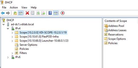
Software Infrastructure Configuration
This section explains how to configure the software infrastructure components that comprise this solution.
Install and configure the infrastructure virtual machines by following the process listed in Table 19.
Table 19. Test Infrastructure Virtual Machine Configuration
| Configuration |
Citrix Virtual Apps and Desktops Controllers Virtual Machines |
Citrix Provisioning Servers Virtual Machines |
| Operating system |
Microsoft Windows Server 2022 |
Microsoft Windows Server 2022 |
| Virtual CPU amount |
6 |
6 |
| Memory amount |
24 GB |
24 GB |
| Network |
VMXNET3 Infra-Mgmt-71 |
VMXNET3 Infra-Mgmt-71 |
| Disk-1 (OS) size |
40 GB |
40 GB |
| Disk-2 size |
- |
200 GB Disk Store |
| Configuration |
Microsoft Active Directory DCs Virtual Machines |
vCenter Server Appliance Virtual Machine |
| Operating system |
Microsoft Windows Server 2022 |
VCSA – SUSE Linux |
| Virtual CPU amount |
4 |
16 |
| Memory amount |
8 GB |
32 GB |
| Network |
VMXNET3 Infra-Mgmt-71 |
VMXNET3 InBand-Mgmt-70 |
| Disk size |
40 GB |
698.84 GB (across 13 VMDKs) |
| Configuration |
Microsoft SQL Server Virtual Machine |
Citrix StoreFront Controller Virtual Machine |
| Operating system |
Microsoft Windows Server 2022 Microsoft SQL Server 2019 |
Microsoft Windows Server 2022 |
| Virtual CPU amount |
6 |
4 |
| Memory amount |
24GB |
8 GB |
| Network |
VMXNET3 Infra-Mgmt-71 |
VMXNET3 Infra-Mgmt-71 |
| Disk-1 (OS) size |
40 GB |
40 GB |
| Disk-2 size |
100 GB SQL Databases\Logs |
- |
This chapter provides guidance regarding creating the golden (or master) images for the environment. Virtual machines for the master targets must first be installed with the software components needed to build the golden images. Additionally, all available security patches as of October 2021 for the Microsoft operating systems, SQL server and Microsoft Office 2021 were installed.
To prepare Single-session OS or Multi-session OS master virtual machine, there are three major steps:
● Installing the PVS Target Device x64 software (if delivered with Citrix Provisioning Services)
● Installing the Virtual Delivery Agents (VDAs)
● Installing application software
For this CVD, the images contain the basics needed to run the Login Enterprise workload.
The Single-session OS and Multi-session OS master target virtual machines were configured as detailed in Table 20.
Table 20. Single-session OS and Multi-session OS Virtual Machine Configurations
| Configuration |
Single-session OS Virtual Machines |
Multi-session OS Virtual Machines |
| Operating system |
Microsoft Windows 11 64-bit |
Microsoft Windows Server 2022 |
| Virtual CPU amount |
2 |
4 |
| Memory amount |
4 GB reserve for all guest memory |
24 GB reserve for all guest memory |
| Network |
VMXNET3 VDI-72 |
VMXNET3 VDI-72 |
| Citrix PVS vDisk size Citrix MCS Disk Size |
48 GB (dynamic) 48 GB |
90 GB (dynamic) |
| Write cache Disk size |
10 GB |
24 GB |
| Citrix PVS write cache RAM cache size |
128 MB |
1024 MB |
| Additional software used for testing |
Microsoft Office 2021 Office Update applied Login Enterprise 7.5.2 |
Microsoft Office 2021 Office Update applied Login Enterprise 7.5.2 |
| Additional Configuration |
Configure DHCP Add to domain Install VMWare tool Install .Net 3.5 Activate Office Install VDA Agent Run PVS Imaging Wizard (For non-persistent Desktops only) |
Configure DHCP Add to domain Install VMWare tool Install .Net 3.5 Activate Office Install VDA Agent Run PVS Imaging Wizard |
Install and Configure Citrix Virtual Apps and Desktops
This chapter contains the following:
● Install Citrix Virtual Apps and Desktops Delivery Controller, Citrix Licensing, and StoreFront
● Install and Configure Citrix Provisioning Server
This chapter explains the installation of the core components of the Citrix Virtual Apps and Desktops system. This CVD installs two Citrix Virtual Apps and Desktops Delivery Controllers to support both hosted shared desktops (HSD), non-persistent hosted virtual desktops (HVD), and persistent hosted virtual desktops (HVD).
Citrix recommends that you use Secure HTTP (HTTPS) and a digital certificate to protect vSphere communications. Citrix recommends that you use a digital certificate issued by a certificate authority (CA) according to your organization's security policy. Otherwise, if the security policy allows, use the VMware-installed self-signed certificate.
Procedure 1. Install vCenter Server Self-signed Certificate
Step 1. Add the FQDN of the computer running vCenter Server to the hosts file on that server, located at SystemRoot/
WINDOWS/system32/Drivers/etc/. This step is required only if the FQDN of the computer running vCenter Server is not already present in DNS.
Step 2. Open Internet Explorer and enter the address of the computer running vCenter Server (for example, https://FQDN as the URL).
Step 3. Accept the security warnings.
Step 4. Click the Certificate Error in the Security Status bar and select View certificates.
Step 5. Click Install certificate, select Local Machine, and then click Next.
Step 6. Select Place all certificates in the following store and then click Browse.
Step 7. Click Show physical stores.
Step 8. Click Trusted People.
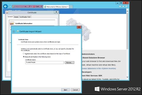
Step 9. Click Next and then click Finish.
Step 10. Repeat steps 1-9 on all Delivery Controllers and Provisioning Servers.
Install Citrix Virtual Apps and Desktops Delivery Controller, Citrix Licensing, and StoreFront
The process of installing the Citrix Virtual Apps and Desktops Delivery Controller also installs other key Citrix Virtual Apps and Desktops software components, including Studio, which is used to create and manage infrastructure components, and Director, which is used to monitor performance and troubleshoot problems.
Note: Dedicated StoreFront and License servers should be implemented for large scale deployments.
Procedure 1. Install Citrix License Server
Step 1. To begin the installation, connect to the first Citrix License server and launch the installer from the Citrix_Virtual_Apps_and_Desktops_7_2203_4000 ISO.
Step 2. Click Start.
Step 3. Click Extend Deployment – Citrix License Server.
Step 4. Read the Citrix License Agreement. If acceptable, indicate your acceptance of the license by selecting the “I have read, understand, and accept the terms of the license agreement” radio button.
Step 5. Click Next.
Step 6. Click Next.
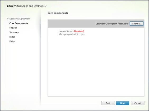
Step 7. Select the default ports and automatically configured firewall rules.
Step 8. Click Next.
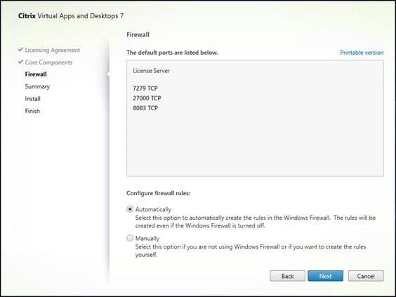
Step 9. Click Install.
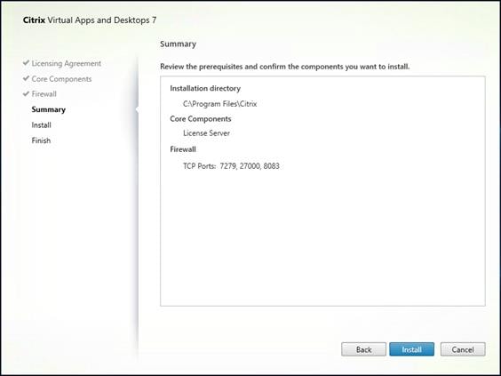
Step 10. Click Finish to complete the installation.
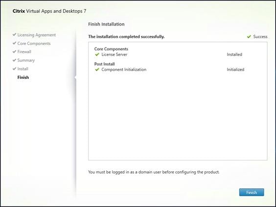
Procedure 2. Install Citrix Licenses
Step 1. Copy the license files to the default location (C:\Program Files (x86)\Citrix\Licensing\ MyFiles) on the license server.
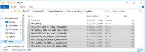
Step 2. Restart the server or Citrix licensing services so that the licenses are activated.
Step 3. Run the application Citrix License Administration Console.
Step 4. Confirm that the license files have been read and enabled correctly.
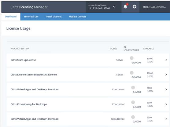
Procedure 3. Install the Citrix Virtual Apps and Desktops
To begin the installation, connect to the first Delivery Controller server and launch the installer from the Citrix_Virtual_Apps_and_Desktops_7_2203_4000 ISO, and follow these steps:
Step 1. Click Start.
Step 2. The installation wizard presents a menu with three subsections. Click Get Started - Delivery Controller.
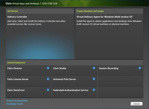
Step 3. Read the Citrix License Agreement. If acceptable, indicate your acceptance of the license by selecting the “I have read, understand, and accept the terms of the license agreement” radio button.
Step 4. Click Next.
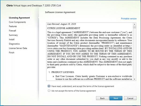
Step 5. Select the components to be installed on the first Delivery Controller Server:
◦ Delivery Controller
◦ Studio
◦ Director
Step 6. Click Next.
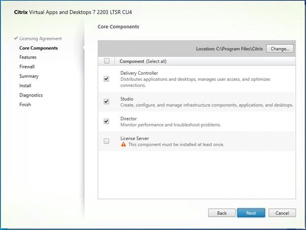
Step 7. Since a dedicated SQL Server will be used to Store the Database, leave “Install Microsoft SQL Server 2014 SP2 Express” unchecked.
Step 8. Click Next.
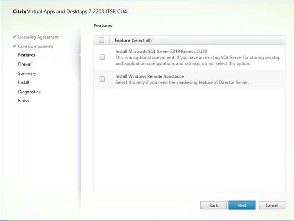
Step 9. Select the default ports and automatically configured firewall rules.
Step 10. Click Next.
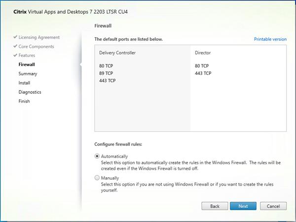
Step 11. Click Install to begin the installation.
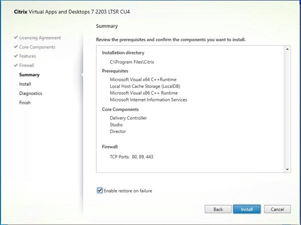
Note: Multiple reboots may be required to finish installation.
Step 12. Optional: Check Collect diagnostic information/Call Home participation.
Step 13. Click Next.
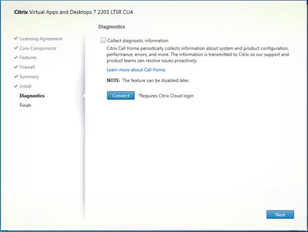
Step 14. Click Finish to complete the installation.
Step 15. Optional: Check Launch Studio to launch Citrix Studio Console.
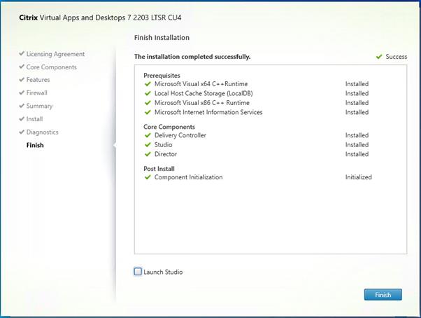
Procedure 4. Additional Delivery Controller Configuration
After the first controller is completely configured and the Site is operational, you can add additional controllers. In this CVD, we created two Delivery Controllers.
To configure additional Delivery Controllers, completed the steps detailed in Install the Citrix Virtual Apps and Desktops.
To begin the installation of the second Delivery Controller, connect to the second Delivery Controller server and launch the installer from the Citrix_Virtual_Apps_and_Desktops_7_2203_4000 ISO.
Step 1. Click Start.
Step 2. Click Delivery Controller.
Step 3. Repeat the same steps used to install the first Delivery Controller; Install the Citrix Virtual Apps and Desktops, including the step of importing an SSL certificate for HTTPS between the controller and vSphere.
Step 4. Review the Summary configuration. Click Finish.
Step 5. Optional: Configure Collect diagnostic information /Call Home participation. Click Next.
Step 6. Verify the components installed successfully. Click Finish.
Citrix Studio is a management console that allows you to create and manage infrastructure and resources to deliver desktops and applications. Replacing Desktop Studio from earlier releases, it provides wizards to set up your environment, create workloads to host applications and desktops, and assign applications and desktops to users.
Citrix Studio launches automatically after the Delivery Controller installation, or if necessary, it can be launched manually. Studio is used to create a Site, which is the core of the Citrix Virtual Apps and Desktops environment consisting of the Delivery Controller and the Database.
Step 1. From Citrix Studio, click Deliver applications and desktops to your users.
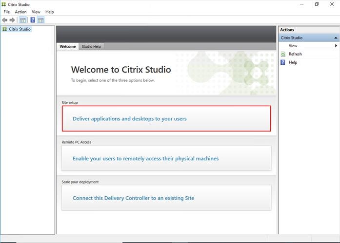
Step 2. Select the “An empty, unconfigured Site” radio button.
Step 3. Enter a site name.
Step 4. Click Next.
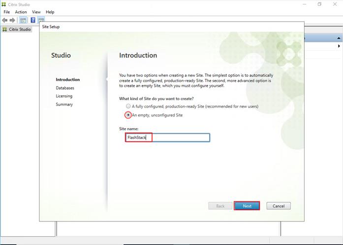
Step 5. Provide the Database Server Locations for each data type.
Step 6. For an SQL AlwaysOn Availability Group, use the group’s listener DNS name.
Step 7. Click Select to specify additional controllers (Optional at this time. Additional controllers can be added later).
Step 8. Click Next.
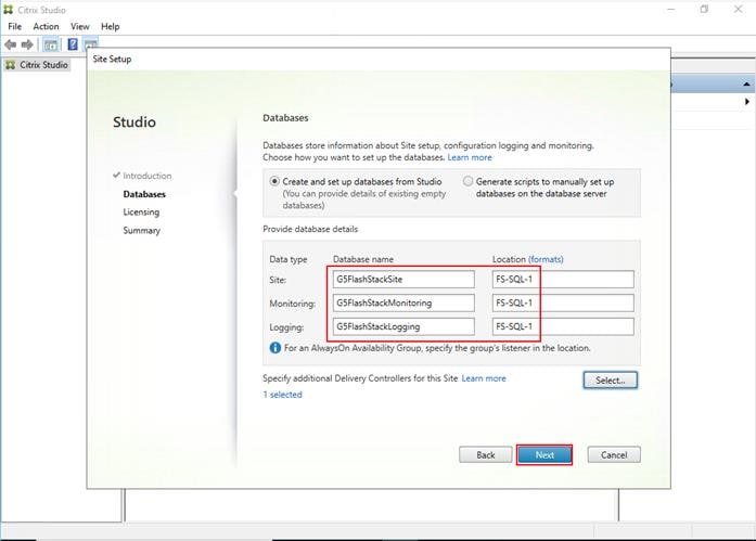
Step 9. Provide the FQDN of the license server.
Step 10. Click Connect to validate and retrieve any licenses from the server.
Note: If no licenses are available, you can use the 30-day free trial or activate a license file.
Step 11. Select the appropriate product edition using the license radio button.
Step 12. Click Next.
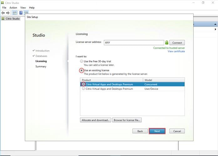
Step 13. Verify information on the Summary page.
Step 14. Click Finish.
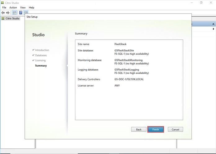
Procedure 6. Configure the Citrix Virtual Apps and Desktops Site Hosting Connection
Step 1. From Configuration > Hosting in Studio, click Add Connection and Resources in the right pane.
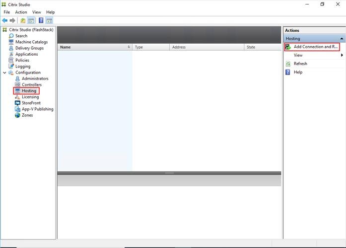
Step 2. On the Connection page:
a. Select the Connection type of VMware vSphere®.
b. Enter the FQDN of the vCenter server (in Server_FQDN/sdk format).
c. Enter the username (in domain\username format) for the vSphere account.
d. Provide the password for the vSphere account.
e. Provide a connection name.
f. Choose the tool to create virtual machines: Machine Creation Services or Citrix Provisioning
Step 3. Click Next.
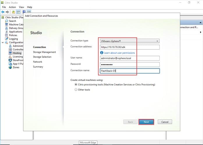
Step 4. Accept the certificate and click OK to trust the hypervisor connection.
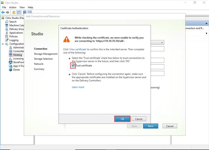
Step 5. Select a storage management method:
◦ Select Cluster that will be used by this connection.
◦ Select the Use storage shared by hypervisors radio button.
Step 6. Click Next.
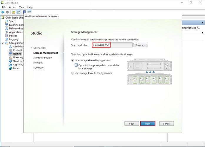
Step 7. Select the Storage to be used by this connection, use all provisioned for desktops datastores.
Step 8. Click Next.
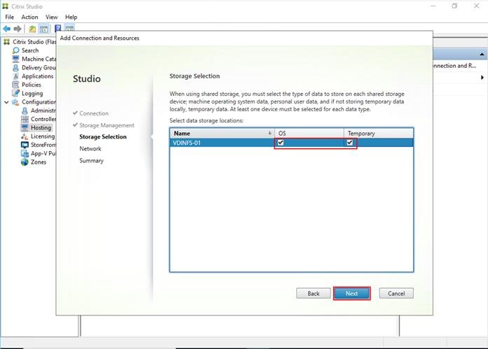
Step 9. Select the Network to be used by this connection.
Step 10. Click Next.
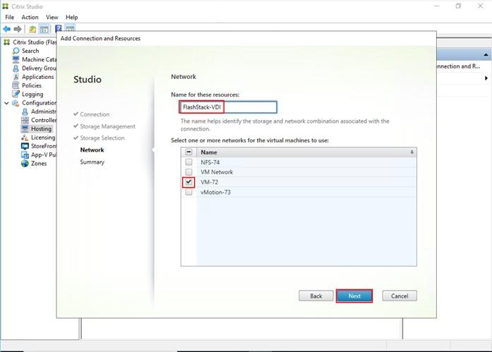
Step 11. Review the Add Connection and Recourses Summary.
Step 12. Click Finish.
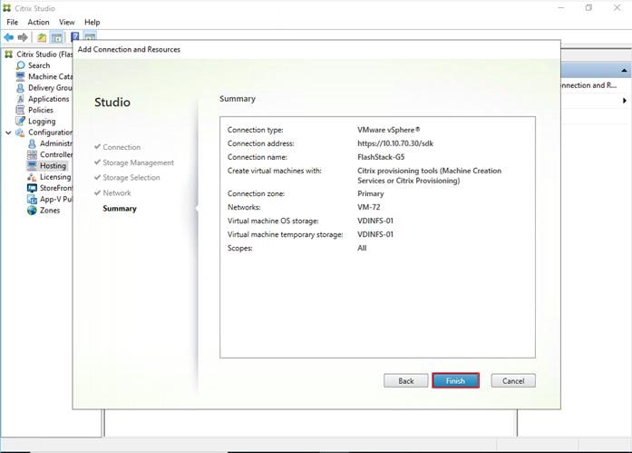
Procedure 7. Configure the Citrix Virtual Apps and Desktops Site Administrators
Step 1. Connect to the Citrix Virtual Apps and Desktops server and open Citrix Studio Management console.
Step 2. From the Configuration menu, right-click Administrator and select Create Administrator from the drop-down list.
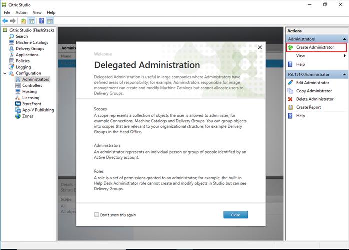
Step 3. Select or Create appropriate scope and click Next.
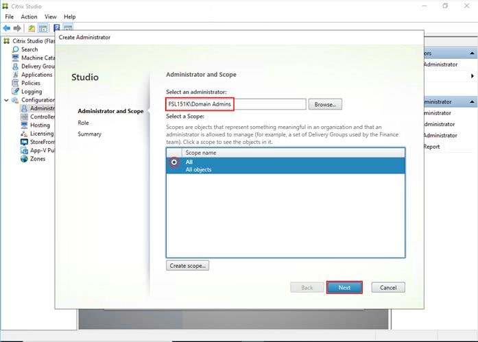
Step 4. Select an appropriate Role.
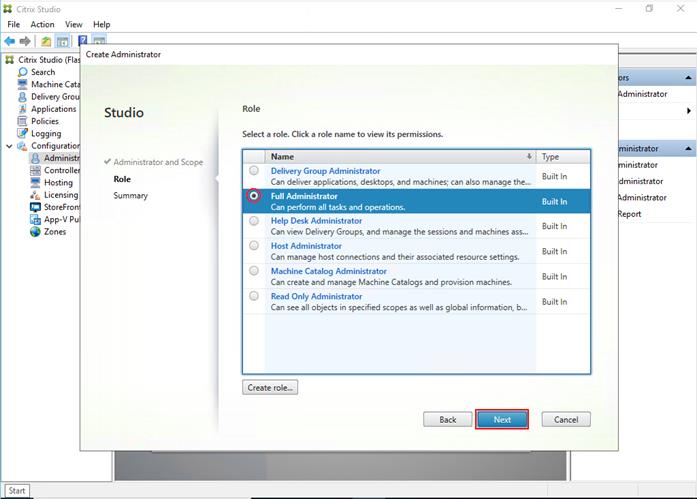
Step 5. Review the Summary, check Enable administrator and click Finish.
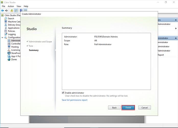
Procedure 8. Install and Configure StoreFront
Citrix StoreFront stores aggregate desktops and applications from Citrix Virtual Apps and Desktops sites, making resources readily available to users. In this CVD, we created two StoreFront servers on dedicated virtual machines.
Step 1. To begin the installation of the StoreFront, connect to the first StoreFront server and launch the installer from the Citrix_Virtual_Apps_and_Desktops_7_2203_4000 ISO.
Step 2. Click Start.

Step 3. Click Extend Deployment Citrix StoreFront.
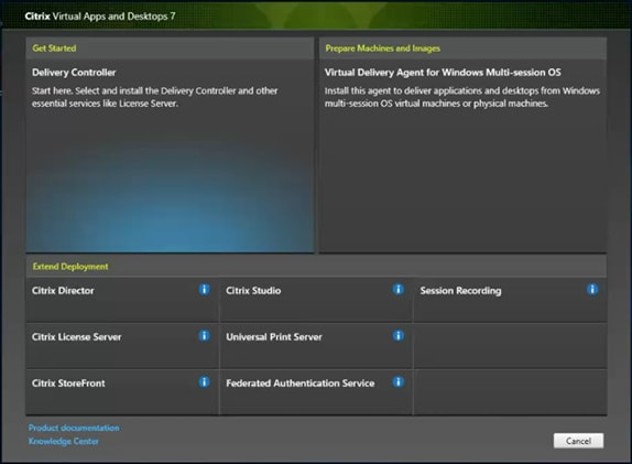
Step 4. Indicate your acceptance of the license by selecting the “I have read, understand, and accept the terms of the license agreement.”
Step 5. Click Next.
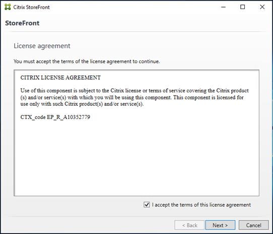
Step 6. On Prerequisites page click Next.
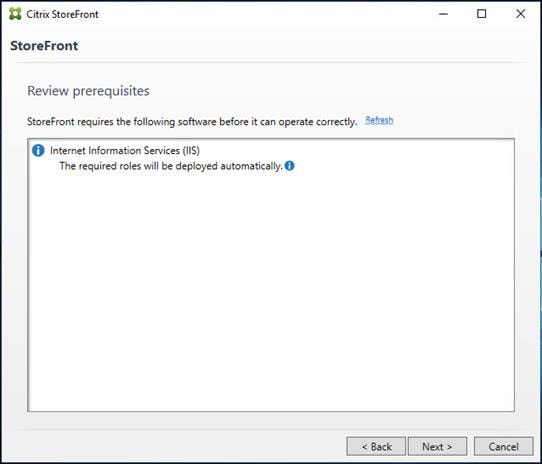
Step 7. Click Install.
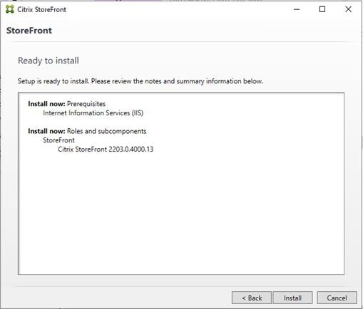
Step 8. Click Finish.
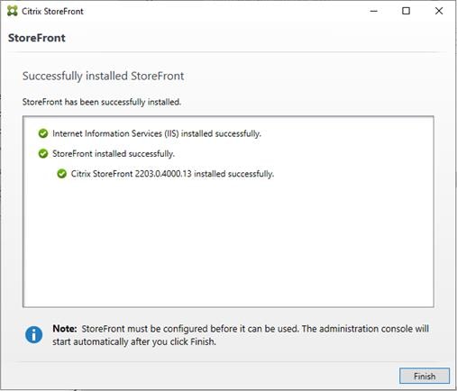
Step 9. Click Yes to reboot the server.
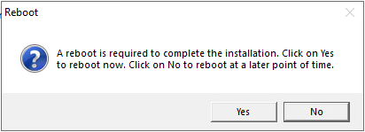
Step 10. Open the StoreFront Management Console.
Step 11. Click Create a new deployment.
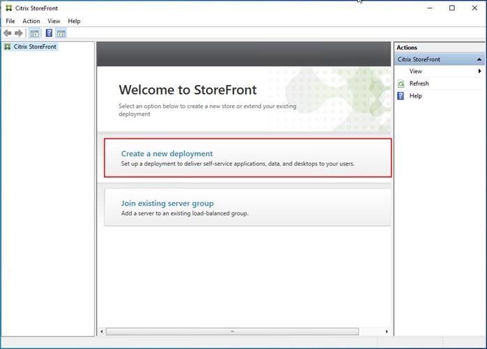
Step 12. Specify name for your Base URL.
Step 13. Click Next.
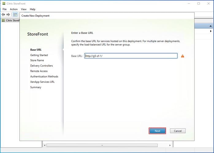
Step 14. For a multiple server deployment use the load balancing environment in the Base URL box.
Step 15. Click Next.
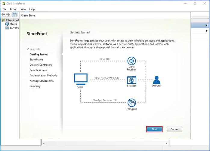
Step 16. Specify a name for your store.
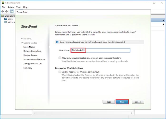
Step 17. Click Add to specify Delivery controllers for your new Store.
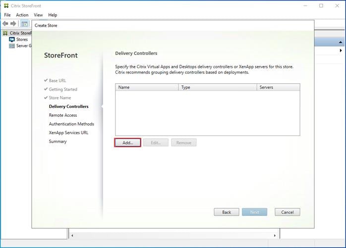
Step 18. Add the required Delivery Controllers to the store.
Step 19. Click OK.
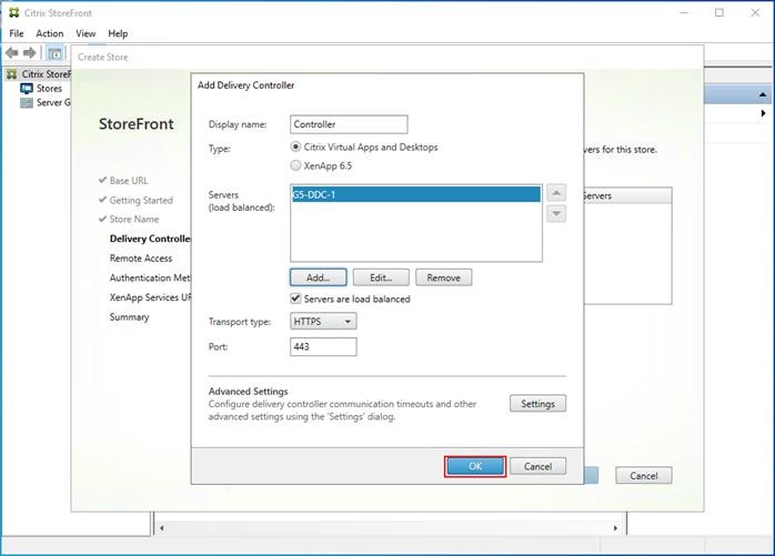
Step 20. Click Next.
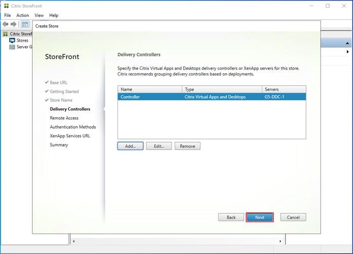
Step 21. Specify how connecting users can access the resources, in this environment only local users on the internal network are able to access the store.
Step 22. Click Next.
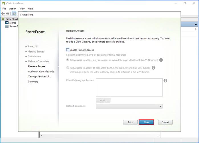
Step 23. On the ”Authentication Methods” page, select the methods your users will use to authenticate to the store. The following methods were configured in this deployment:
● Username and password: Users enter their credentials and are authenticated when they access their stores.
● Domain passthrough: Users authenticate to their domain-joined Windows computers and their credentials are used to log them on automatically when they access their stores.
Step 24. Click Next.
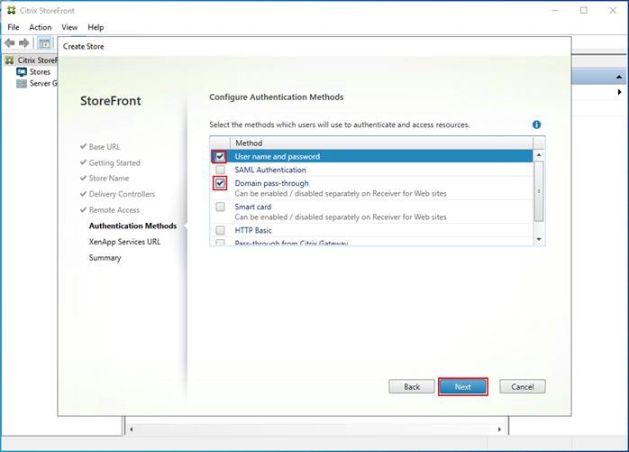
Step 25. Configure the XenApp Service URL for users who use PNAgent to access the applications and desktops.
Step 26. Click Create.
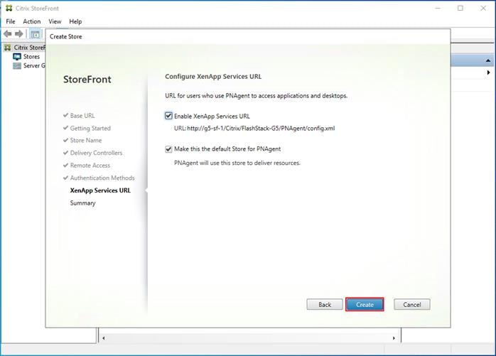
Step 27. After creating the store click Finish.
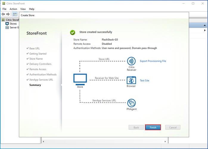
Procedure 9. Configure Additional StoreFront Servers
After the first StoreFront server is completely configured and the Store is operational, you can add additional servers.
Step 1. Install the second StoreFront using the same installation steps outlined above.
Step 2. Connect to the first StoreFront server
Step 3. To add the second server and generate the authorization information that allows the additional StoreFront server to join the server group, select Add Server from Actions pane in the Server Group.
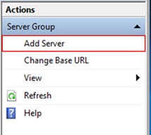
Step 4. Copy the authorization code.
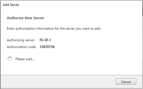
Step 5. From the StoreFront Console on the second server select “Join existing server group.”
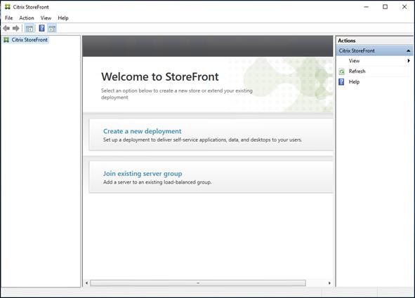
Step 6. In the Join Server Group dialog, enter the name of the first Storefront server and paste the Authorization code into the Join Server Group dialog.
Step 7. Click Join.
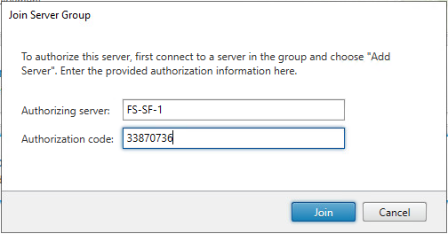
A message appears when the second server has joined successfully.
Step 8. Click OK.
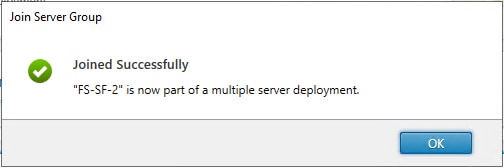
The second StoreFront is now in the Server Group.
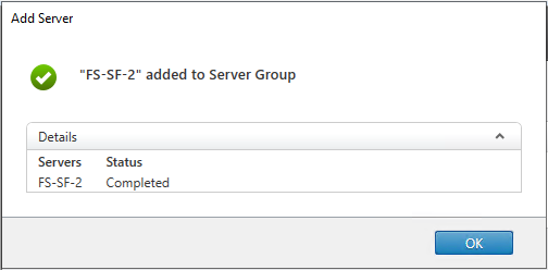
Install and Configure Citrix Provisioning Server
In most implementations, there is a single vDisk providing the standard image for multiple target devices. Thousands of target devices can use a single vDisk shared across multiple Provisioning Services (PVS) servers in the same farm, simplifying virtual desktop management. This section describes the installation and configuration tasks required to create a PVS implementation.
The PVS server can have many stored vDisks, and each vDisk can be several gigabytes in size. Your streaming performance and manageability can be improved using a RAID array, SAN, or NAS. PVS software and hardware requirements are available in the Provisioning Services 2203 LTSR document.
Procedure 1. Configure Prerequisites
Step 1. Set the following Scope Options on the DHCP server hosting the PVS target machines:
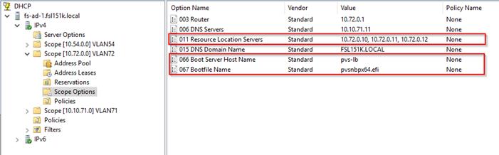
Step 2. Create a DNS host records with multiple PVS Servers IP for TFTP Load Balancing:
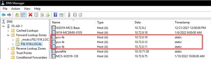
Step 3. As a Citrix best practice cited in this CTX article, apply the following registry setting both the PVS servers and target machines:
HKEY_LOCAL_MACHINE\SYSTEM\CurrentControlSet\Services\TCPIP\Parameters\
Key: "DisableTaskOffload" (dword)
Value: "1"
Note: Only one MS SQL database is associated with a farm. You can choose to install the Provisioning Services database software on an existing SQL database, if that machine can communicate with all Provisioning Servers within the farm, or with a new SQL Express database machine, created using the SQL Express software that is free from Microsoft.
These databases are supported: Microsoft SQL Server 2008 SP3 through 2016 (x86, x64, and Express editions). Please check the Citrix documentation for further reference.
Note: Microsoft SQL 2019 was installed separately for this CVD.
Procedure 2. Install and Configure Citrix Provisioning Service 2109
Step 1. Connect to Citrix Provisioning server and launch Citrix Provisioning Services 2109 ISO and let AutoRun launch the installer.
Step 2. Click Console Installation.
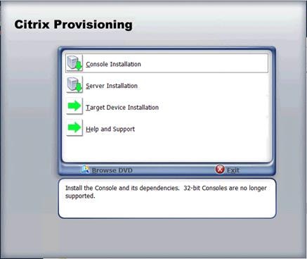
Step 3. Click Install to start the console installation.
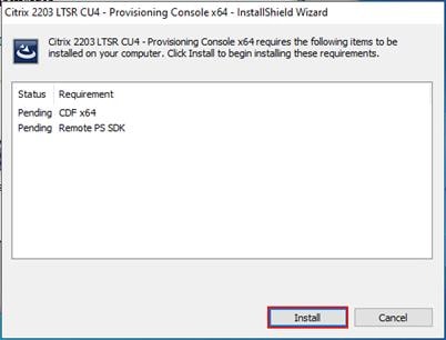
Step 4. Click Next.
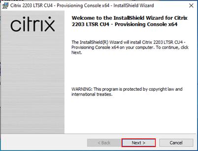
Step 5. Read the Citrix License Agreement. If acceptable, select the radio button labeled “I accept the terms in the license agreement.”
Step 6. Click Next.
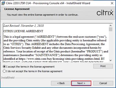
Step 7. Optional: Provide a User Name and Organization.
Step 8. Click Next.
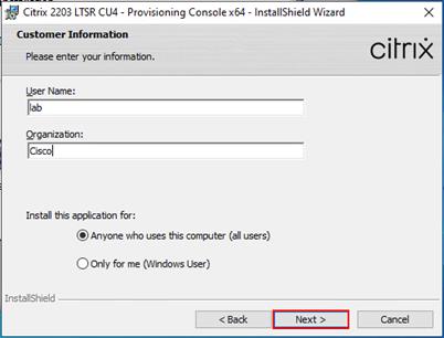
Step 9. Accept the default path.
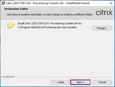
Step 10. Click Install.
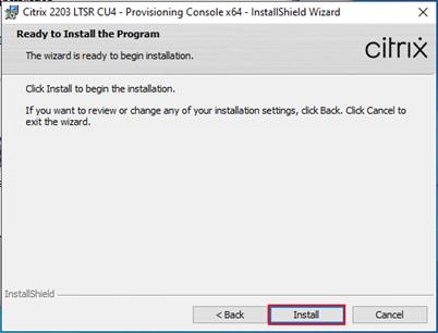
Step 11. Click Finish after successful installation.
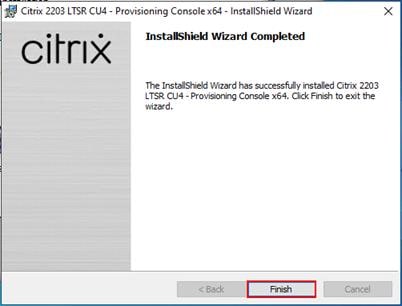
Step 12. From the main installation screen, select Server Installation.
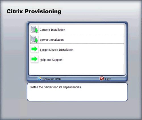
Step 13. Click Install on the prerequisites dialog.
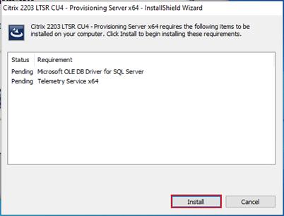
Step 14. When the installation wizard starts, click Next.
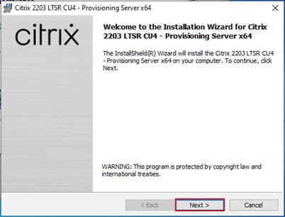
Step 15. Review the license agreement terms. If acceptable, select the radio button labeled “I accept the terms in the license agreement.”
Step 16. Click Next.
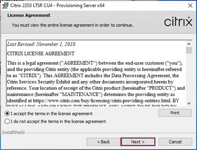
Step 17. Select Automatically open Citrix PVS Firewall Ports.
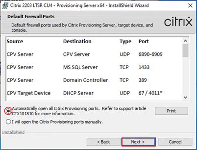
Step 18. Provide User Name and Organization information. Select who will see the application.
Step 19. Click Next.
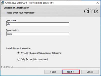
Step 20. Accept the default installation location.
Step 21. Click Next.
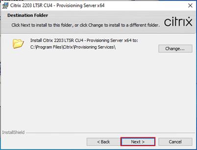
Step 22. Click Install to begin the installation.

Step 23. Click Finish when the install is complete.
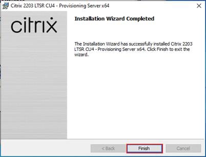
Procedure 3. Configure Citrix Provisioning
Note: If Citrix Provisioning services configuration wizard doesn’t start automatically, follow these steps:
Step 1. Start PVS Configuration Wizard.
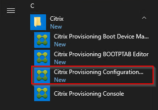
Step 2. Click Next.
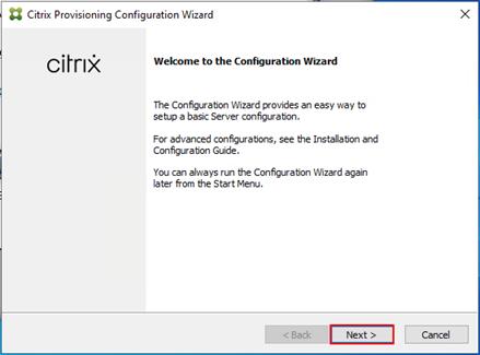
Step 3. Since the PVS server is not the DHCP server for the environment, select the radio button labeled, “The service that runs on another computer.”
Step 4. Click Next.
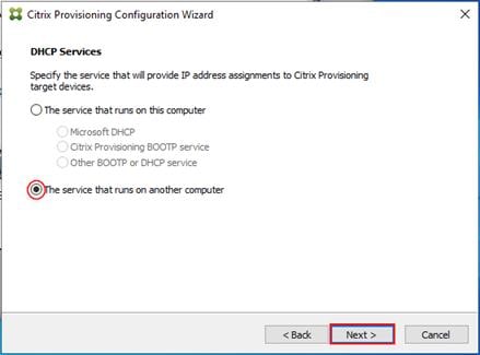
Step 5. Since DHCP boot options are used for TFTP services, select the radio button labeled “The service that runs on another computer.”
Step 6. Click Next.
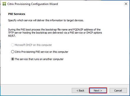
Step 7. Since this is the first server in the farm, select the radio button labeled “Create farm.”
Step 8. Click Next.
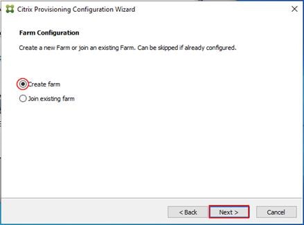
Step 9. Enter the FQDN of the SQL server.
Step 10. Click Next.
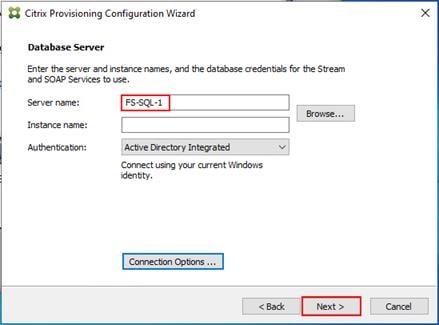
Step 11. Provide the Database, Farm, Site, and Collection name.
Step 12. Click Next.
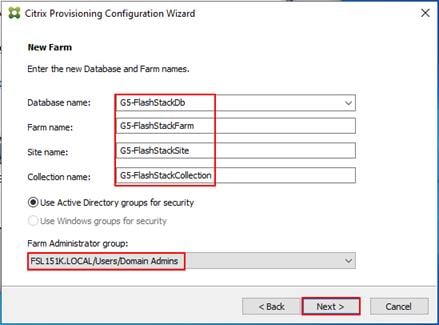
Step 13. Provide the vDisk Store details.
Step 14. Click Next.
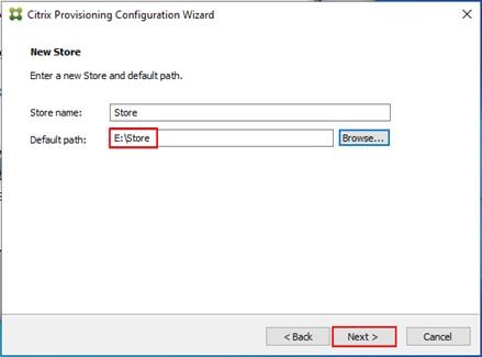
Step 15. For large scale PVS environment, it is recommended to create the share using support for CIFS/SMB3 on an enterprise ready File Server.
Step 16. Provide the FQDN of the license server.
Step 17. Optional: Provide a port number if changed on the license server.
Step 18. Click Next.
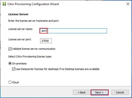
Step 19. If an Active Directory service account is not already setup for the PVS servers, create that account prior to clicking Next on this dialog.
Step 20. Select the Specified user account radio button.
Step 21. Complete the User name, Domain, Password, and Confirm password fields, using the PVS account information created earlier.
Step 22. Click Next.
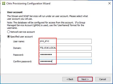
Step 23. Set the Days between password updates to 7.
Note: This will vary per environment. “7 days” for the configuration was appropriate for testing purposes.
Step 24. Click Next.
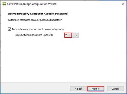
Step 25. Keep the defaults for the network cards.
Step 26. Click Next.
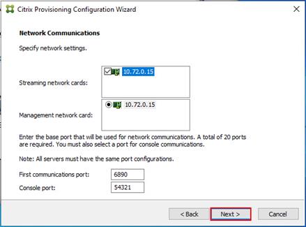
Step 27. Select Use the Provisioning Services TFTP service checkbox.
Step 28. Click Next.
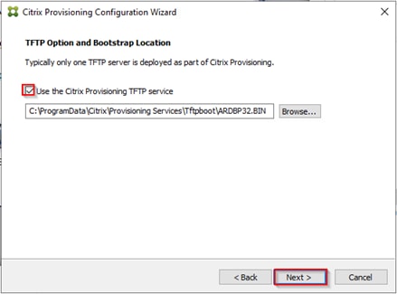
Step 29. If Soap Server is used, provide details.
Step 30. Click Next.
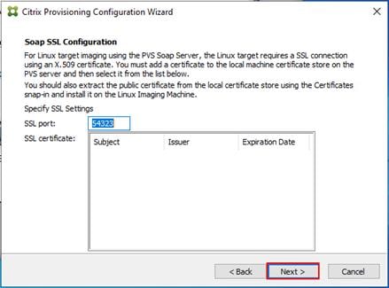
Step 31. If desired fill in Problem Report Configuration.
Step 32. Click Next.
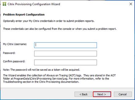
Step 33. Click Finish to start the installation.
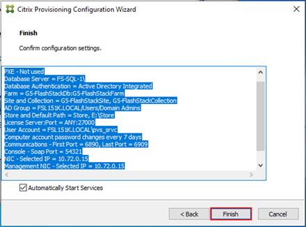
Step 34. When the installation is completed, click Done.
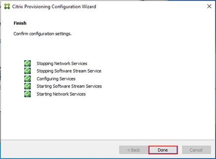
Procedure 4. Install Additional PVS Servers
Complete the installation steps on the additional PVS servers up to the configuration step where it asks to Create or Join a farm. In this CVD, we repeated the procedure to add a total of three PVS servers.
Step 1. On the Farm Configuration dialog, select Join existing farm.
Step 2. Click Next.
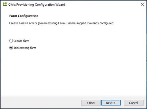
Step 3. Provide the FQDN of the SQL Server and select appropriate authentication method
Step 4. Click Next.
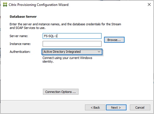
Step 5. Accept the Farm Name.
Step 6. Click Next.
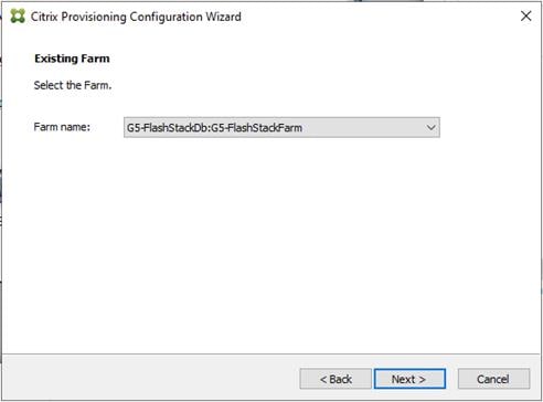
Step 7. Accept the Existing Site.
Step 8. Click Next.
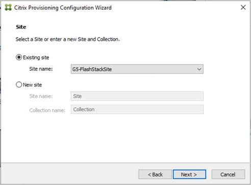
Step 9. Accept the existing vDisk store.
Step 10. Click Next.

Step 11. Provide the FQDN of the license server.
Step 12. Optional: Provide a port number if changed on the license server.
Step 13. Click Next.
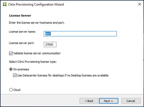
Step 14. Provide the PVS service account information.
Step 15. Click Next.
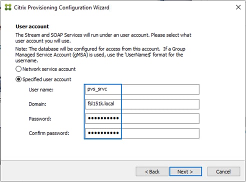
Step 16. Set the Days between password updates to 7.
Step 17. Click Next.
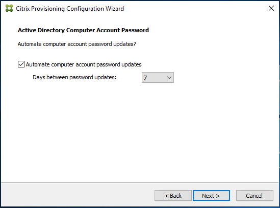
Step 18. Accept the network card settings.
Step 19. Click Next.
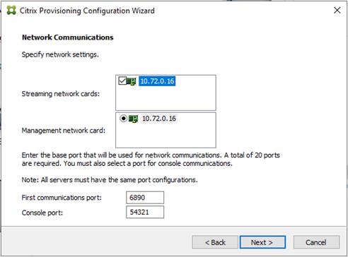
Step 20. Check the box for Use the Provisioning Services TFTP service.
Step 21. Click Next.
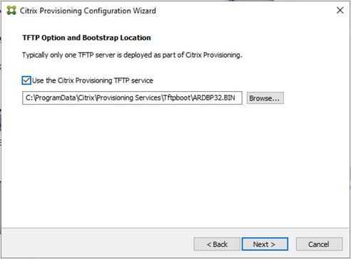
Step 22. Click Next.
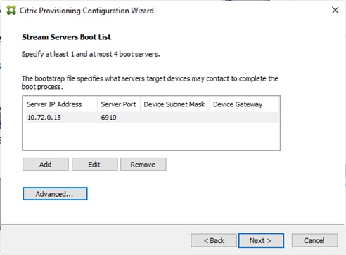
Step 23. If Soap Server is used, provide details.
Step 24. Click Next.
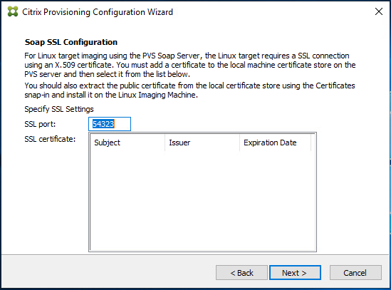
Step 25. If desired, fill in Problem Report Configuration.
Step 26. Click Next.
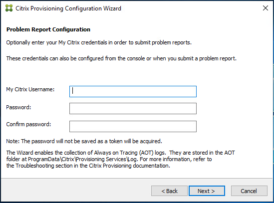
Step 27. Click Finish to start the installation process.
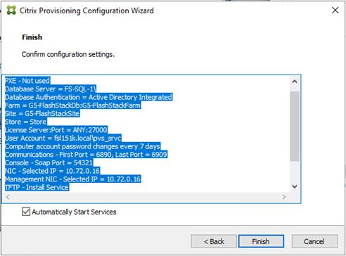
Step 28. Click Done when the installation finishes.
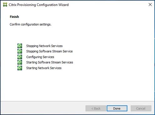
Note: You can optionally install the Provisioning Services console on the second PVS server following the procedure in the section Installing Provisioning Services.
Step 29. After completing the steps to install the three additional PVS servers, launch the Provisioning Services Console to verify that the PVS Servers and Stores are configured and that DHCP boot options are defined.
Step 30. Launch Provisioning Services Console and select Connect to Farm.
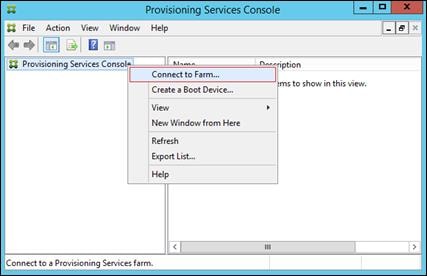
Step 31. Enter localhost for the PVS1 server.
Step 32. Click Connect.
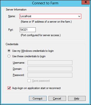
Step 33. Select Store Properties from the drop-down list.
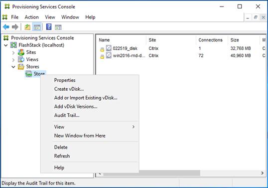
Step 34. In the Store Properties dialog, add the Default store path to the list of Default write cache paths.

Step 35. Click Validate. If the validation is successful, click Close and then click OK to continue.
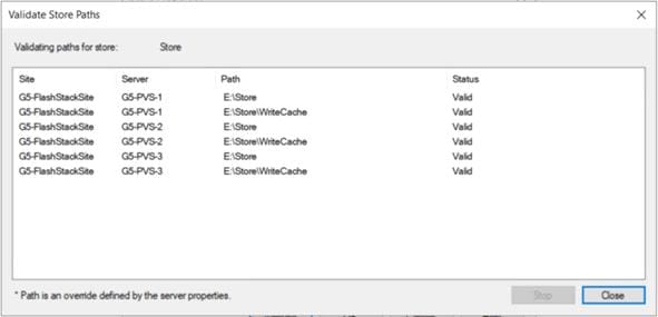
Procedure 5. Install Citrix Virtual Apps and Desktops Virtual Desktop Agents
Virtual Delivery Agents (VDAs) are installed on the server and workstation operating systems and enable connections for desktops and apps. The following procedure was used to install VDAs for both Single-session OS and Multi-session OS.
By default, when you install the Virtual Delivery Agent, Citrix User Profile Management is installed silently on master images. (Using profile management as a profile solution is optional but FSLogix was used for this CVD and is described in a later section.)
Step 1. Launch the Citrix Virtual Apps and Desktops installer from the Citrix_Virtual_Apps_and_Desktops_7_2203_4000 ISO.
Step 2. Click Start on the Welcome Screen.

Step 3. To install the VDA for the Hosted Virtual Desktops (VDI), select Virtual Delivery Agent for Windows Single-session OS.
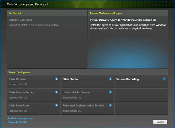
Step 4. Select Create a master MCS Image.
Step 5. Click Next.
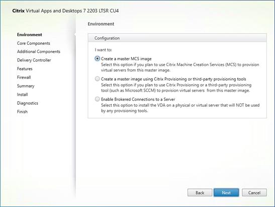
Step 6. Select “Create a master image using Citrix Provisioning or third-party provisioning tools” when building image to be delivered with Citrix Provisioning tools.
![]()
Step 7. Optional: Do not select Citrix Workspace App.
Step 8. Click Next.
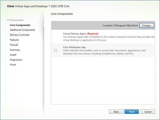
Step 9. Select the additional components required for your image. In this design, only default components were installed on the image.
Step 10. Click Next.
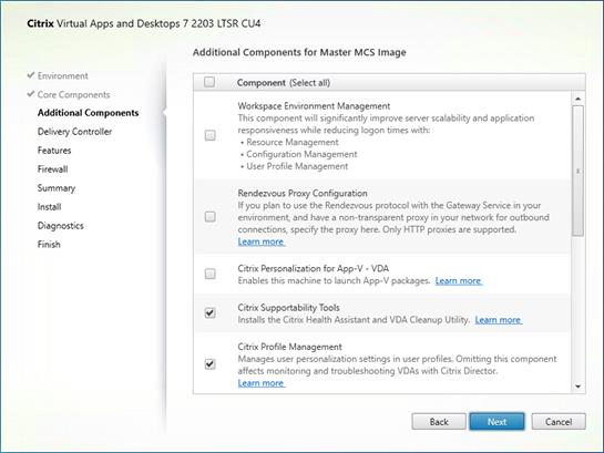
Step 11. Configure Delivery Controllers at this time.
Step 12. Click Next.
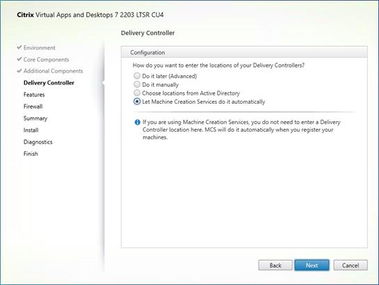
Step 13. Optional: Select additional features.
Step 14. Click Next.
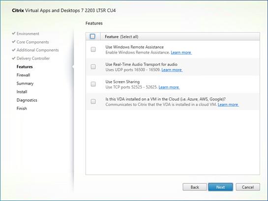
Step 15. Allow the firewall rules to be configured Automatically.
Step 16. Click Next.
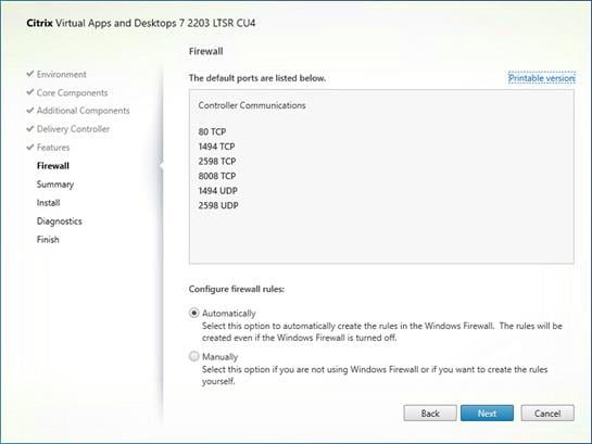
Step 17. Verify the Summary and click Install.
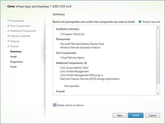
Step 18. Optional: Configure Citrix Call Home participation.
Step 19. Click Next.
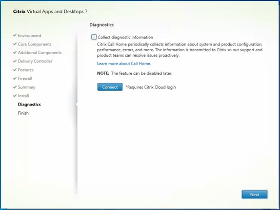
Step 20. Check Restart Machine.
Step 21. Click Finish and the machine will reboot automatically.
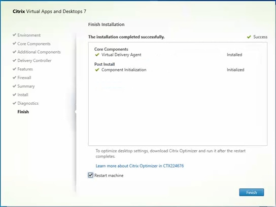
Procedure 6. Install the Citrix Provisioning Server Target Device Software
The Master Target Device refers to the target device from which a hard disk image is built and stored on a vDisk. Provisioning Services then streams the contents of the vDisk created to other target devices. This procedure installs the PVS Target Device software that is used to build the RDS and VDI golden images.
Step 1. Launch the PVS installer from the Citrix_Provisioning_2203_CU4 ISO.
Step 2. Click Target Device Installation.
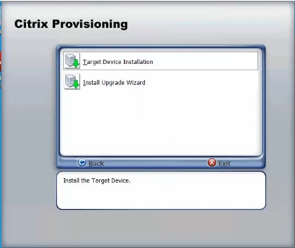
Step 3. The installation wizard will check to resolve dependencies and then begin the PVS target device installation process.
Step 4. Click Next.
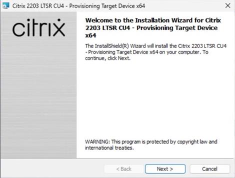
Step 5. Indicate your acceptance of the license by selecting the “I have read, understand, and accept the terms of the license agreement” radio button.
Step 6. Click Next.
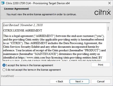
Step 7. Optional: Provide the Customer information.
Step 8. Click Next.
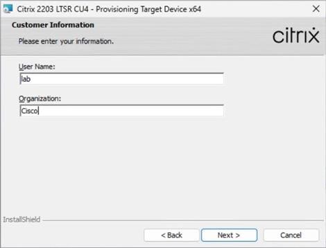
Step 9. Accept the default installation path.
Step 10. Click Next.
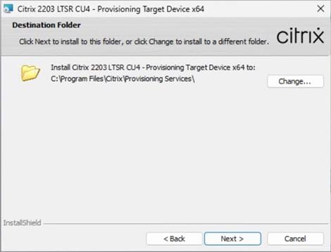
Step 11. Click Install.
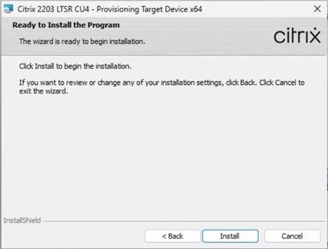
Step 12. Deselect the checkbox to launch the Imaging Wizard and click Finish.
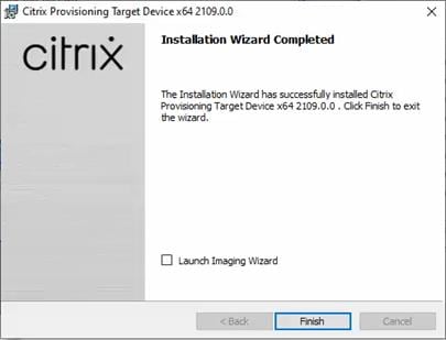
Step 13. Click Yes to reboot the machine.
Procedure 7. Create Citrix Provisioning Server vDisks
The PVS Imaging Wizard automatically creates a base vDisk image from the master target device.
The PVS Imaging Wizard's Welcome page appears.
Step 1. Click Next.
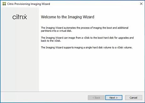
Step 2. The Connect to Farm page appears. Enter the name or IP address of a Provisioning Server within the farm to connect to and the port to use to make that connection.
Step 3. Use the Windows credentials (default) or enter different credentials.
Step 4. Click Next.
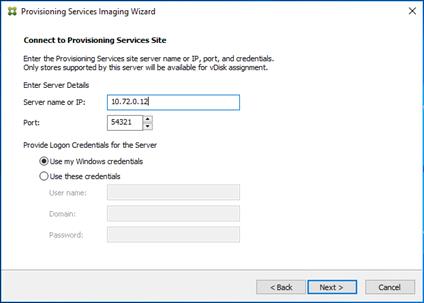
Step 5. Select Create a vDisk.
Step 6. Click Next.
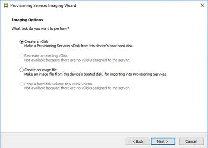
The Add Target Device page appears.
Step 7. Select the Target Device Name, the MAC address associated with one of the NICs that was selected when the target device software was installed on the master target device, and the Collection to which you are adding the device.
Step 8. Click Next.
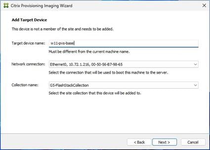
Step 9. The New vDisk dialog displays. Enter the name of the vDisk.
Step 10. Select the Store where the vDisk will reside. Select the vDisk type, either Fixed or Dynamic, from the drop-down list.
Note: This CVD used Dynamic rather than Fixed vDisks.
Step 11. Click Next.
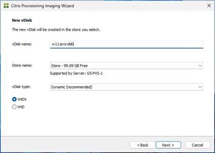
Step 12. On the Microsoft Volume Licensing page, select the volume license option to use for target devices. For this CVD, volume licensing is not used, so the None button is selected.
Step 13. Click Next.
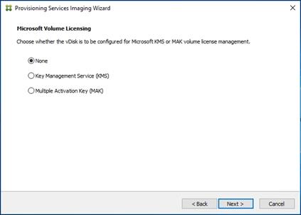
Step 14. Select Image entire boot disk on the Configure Image Volumes page.
Step 15. Click Next.
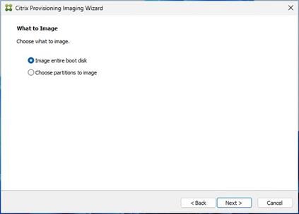
Step 16. Select Optimize for hard disk again for Provisioning Services before imaging on the Optimize Hard Disk for Provisioning Services.
Step 17. Click Next.
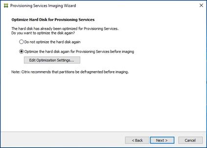
Step 18. Click Create on the Summary page.
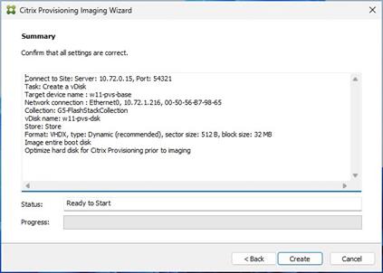
Step 19. Review the configuration and click Continue.
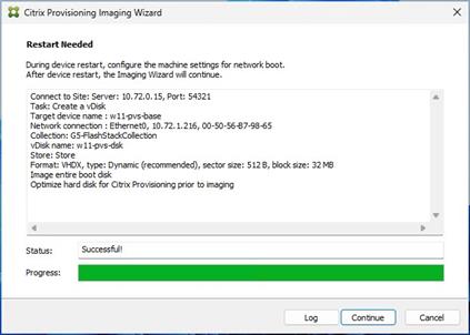
Step 20. When prompted, click No to shut down the machine.
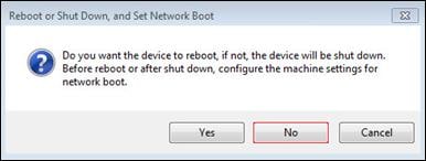
Step 21. Edit the VM settings and select Force EFI Setup under Boot Options.
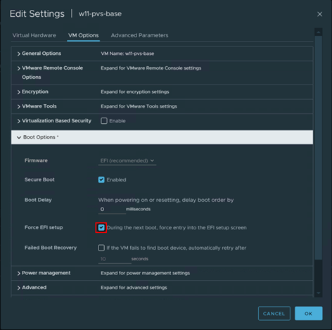
Step 22. Enter setup and click Enter on Configure boot options.
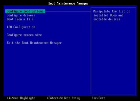
Step 23. Configure the VM settings for EFI network boot.
Step 24. Click Commit changes and exit.
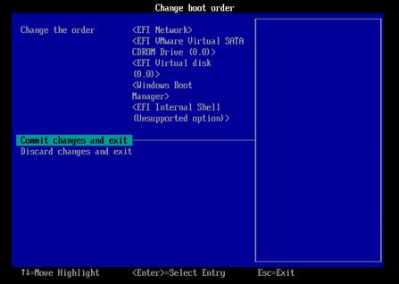
Step 25. After restarting the virtual machine, log into the master target. The PVS imaging process begins, copying the contents of the C: drive to the PVS vDisk located on the server.
Step 26. If prompted to Format disk, disregard the message, and allow Provisioning Imaging Wizard to finish.
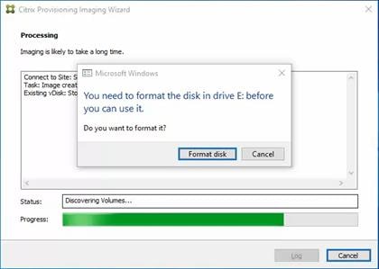
Step 27. A message is displayed when the conversion is complete, click Done.
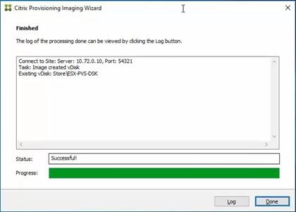
Step 28. Shutdown the virtual machine used as the VDI or RDS master target.
Step 29. Connect to the PVS server and validate that the vDisk image is available in the Store.
Step 30. Right-click the newly created vDisk and select Properties.
Step 31. On the vDisk Properties dialog, change Access mode to “Standard Image (multi-device, read-only access).”
Step 32. Set the Cache Type to “Cache in device RAM with overflow on hard disk.”
Step 33. Set Maximum RAM size (MBs): 128.
Step 34. Click OK.
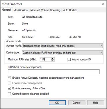
Provision Virtual Desktop Machines
This chapter contains the following:
● Citrix Provisioning Services
● Citrix Machine Creation Services
● Citrix Virtual Apps and Desktops Policies and Profile Management
This section provides the procedures for Citrix Provisioning Service.
Procedure 1. Citrix Provisioning Services Citrix Virtual Desktop Setup Wizard - Create PVS Streamed Virtual Desktop Machines
Step 1. Create a Master Target Virtual Machine:
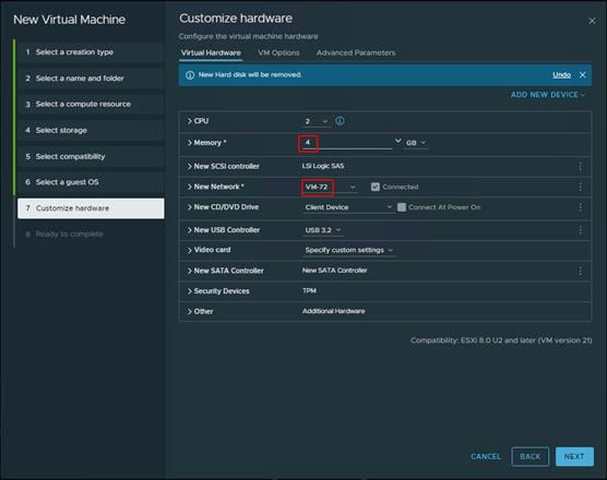
Step 2. Right-click and clone the Master Target VM to the Template.
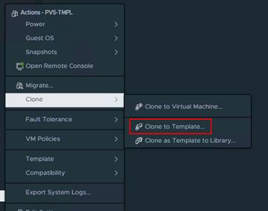
Step 3. Start the Citrix Virtual Apps and Desktops Setup Wizard from the Provisioning Services Console.
Step 4. Right-click the Site.
Step 5. Select Citrix Virtual Desktop Setup Wizard… from the context menu.
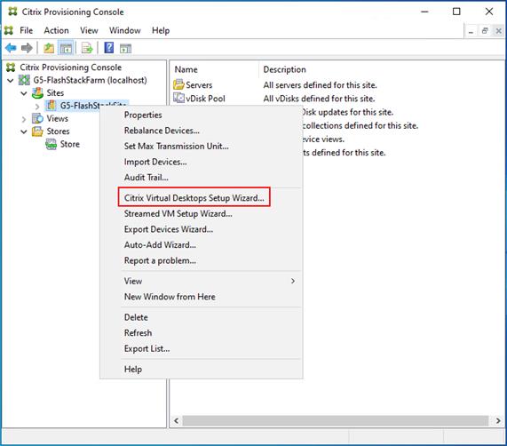
Step 6. Click Next.
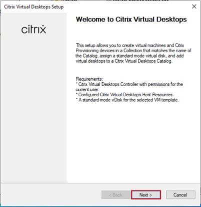
Step 7. Enter the address of the Citrix Virtual Desktop Controller that will be used for the wizard operations.
Step 8. Click Next.
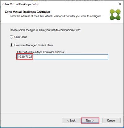
Step 9. Select Host Resources that will be used for the wizard operations
Step 10. Click Next.
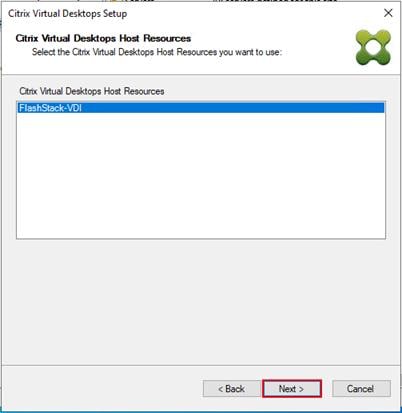
Step 11. Provide Citrix Virtual Desktop Controller credentials.
Step 12. Click OK.
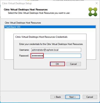
Step 13. Select the Template created earlier.
Step 14. Click Next.
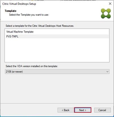
Step 15. Select the virtual disk (vDisk) that will be used to stream the provisioned virtual machines.
Step 16. Click Next.
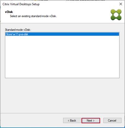
Step 17. Select Create new catalog.
Step 18. Provide a catalog name.
Step 19. Click Next.
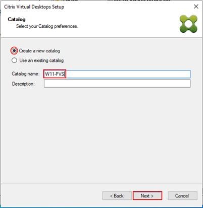
Step 20. Select Single-session OS for Machine catalog Operating System.
Step 21. Click Next.
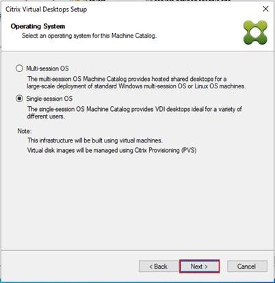
Note: Select Multi-session OS when using Windows Server 2022 desktops.
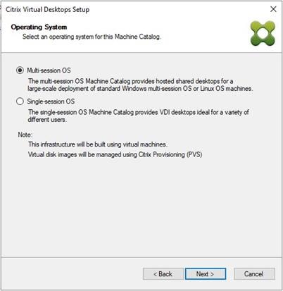
Step 22. Select random for the User Experience.
Step 23. Click Next.
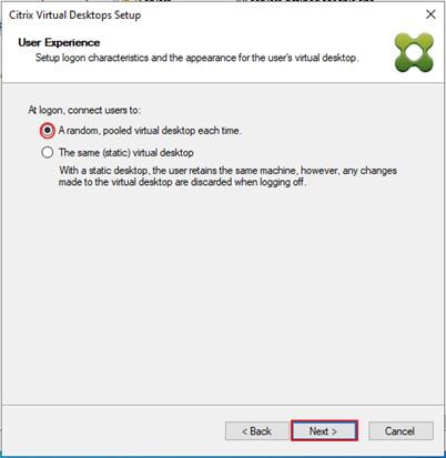
Step 24. On the Virtual machines dialog, specify the following:
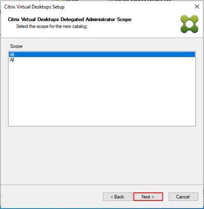
Step 25. On the Virtual machines dialog, specify the following:
◦ The number of virtual machines to create.
Note: It is recommended to create 200 or less per provisioning run. Create a single virtual machine at first to verify the procedure.
◦ 2 as Number of vCPUs for the virtual machine
◦ 4096 MB as the amount of memory for the virtual machine
◦ 6GB as the Local write cache disk.
Step 26. Click Next.
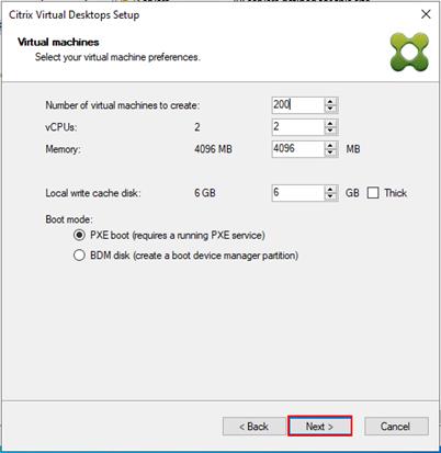
Step 27. Select the Create new accounts.
Step 28. Click Next.

Step 29. Specify the Active Directory Accounts and Location. This is where the wizard should create computer accounts.
Step 30. Provide the Account naming scheme. An example name is shown in the text box below the naming scheme selection location.
Step 31. Click Next.
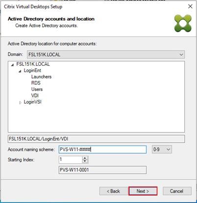
Step 32. Verify the information on the Summary screen.
Step 33. Click Finish to begin the virtual machine creation.
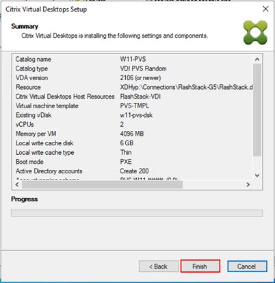
Step 34. When the wizard is done provisioning the virtual machines, click Done.
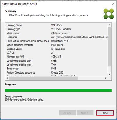
Step 35. When the wizard is done provisioning the virtual machines, verify the Machine Catalog on the Citrix Virtual Apps and Desktops Controller.
Step 36. Connect to a Citrix Virtual Apps and Desktops server and launch Citrix Studio.
Step 37. Select Machine Catalogs in the Studio navigation pane.
Step 38. Select a machine catalog.
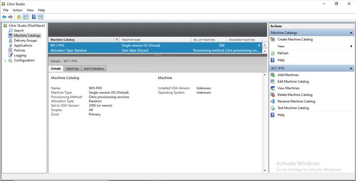
Citrix Machine Creation Services
This section provides the procedures to set up and configure Citrix Machine creation services.
Procedure 1. Machine Catalog Setup
Step 1. Connect to a Citrix Virtual Apps and Desktops server and launch Citrix Studio.
Step 2. Select Create Machine Catalog from the Actions pane.
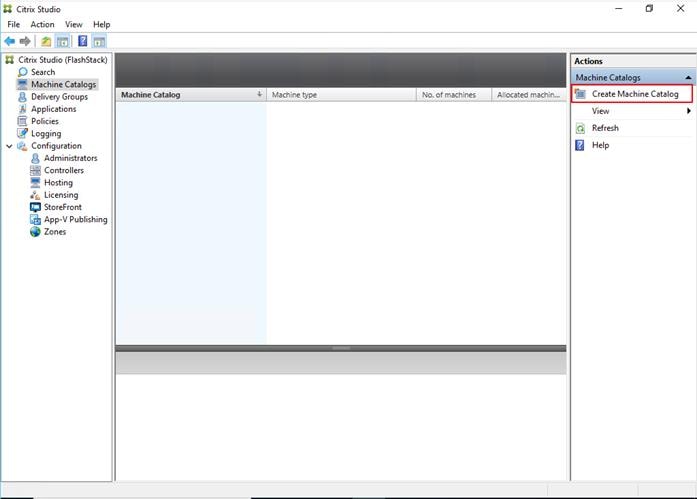
Step 3. Click Next.
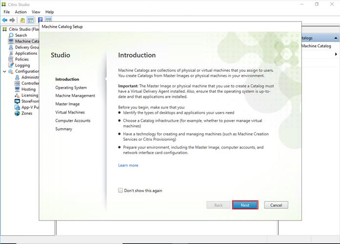
Step 4. Select Single-session OS.
Step 5. Click Next.
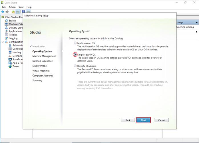
Step 6. Select the appropriate machine management.
Step 7. Click Next.
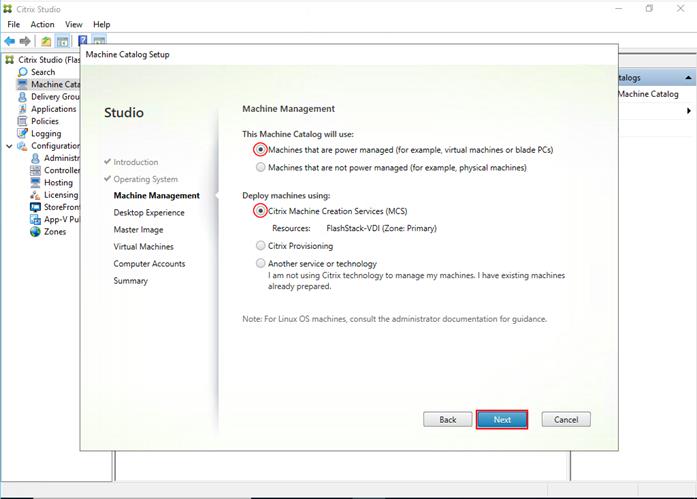
Step 8. Select (random) for Desktop Experience.
Step 9. Click Next.
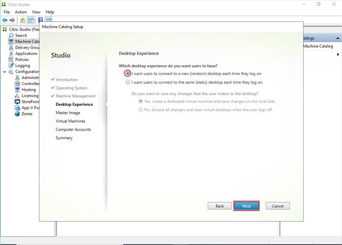
Step 10. Select a Virtual Machine to be used for Catalog Master Image.
Step 11. Click Next.
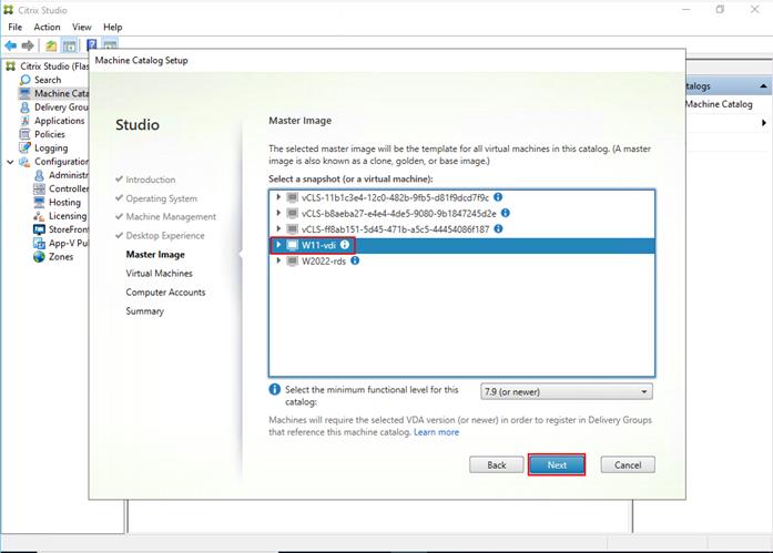
Step 12. Specify the number of desktops to create and machine configuration.
Step 13. Set amount of memory (MB) to be used by virtual desktops.
Step 14. Select Full Copy for machine copy mode.
Step 15. Click Next.
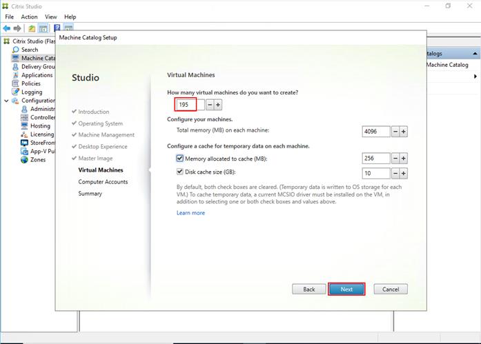
Step 16. Specify the AD account naming scheme and OU where accounts will be created.
Step 17. Click Next.
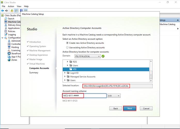
Step 18. On the Summary page specify Catalog name and click Finish to start the deployment.
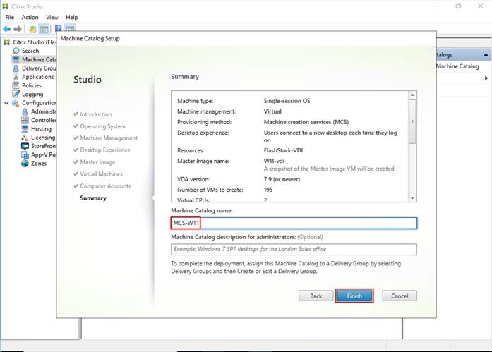
Delivery Groups are collections of machines that control access to desktops and applications. With Delivery Groups, you can specify which users and groups can access which desktops and applications.
Procedure 1. Create Delivery Groups
This procedure details how to create a Delivery Group for persistent VDI desktops. When you have completed these steps, repeat the procedure for a Delivery Group for RDS desktops.
Step 1. Connect to a Citrix Virtual Apps and Desktops server and launch Citrix Studio.
Step 2. Choose Create Delivery Group from the drop-down list.
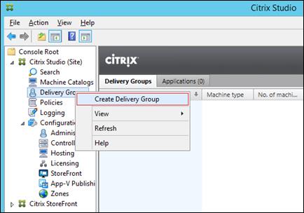
Step 3. Click Next.
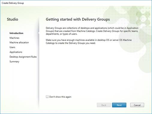
Step 4. Specify the Machine Catalog and increment the number of machines to add.
Step 5. Click Next.
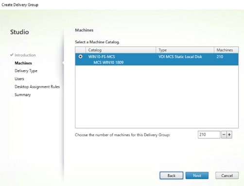
Step 6. Specify what the machines in the catalog will deliver: Desktops, Desktops and Applications, or Applications.
Step 7. Select Desktops.
Step 8. Click Next.
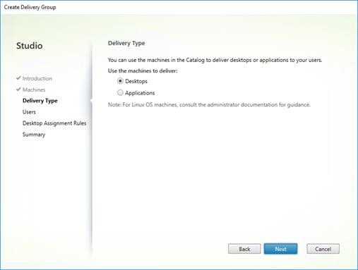
Step 9. To make the Delivery Group accessible, you must add users. Select Allow any authenticated users to use this Delivery Group.
Step 10. User assignment can be updated any time after Delivery group creation by accessing Delivery group properties in Desktop Studio.
Step 11. Click Next.
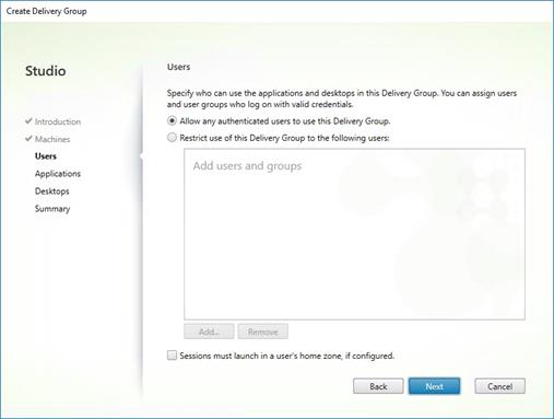
Step 12. Click Next (no applications are used in this design).
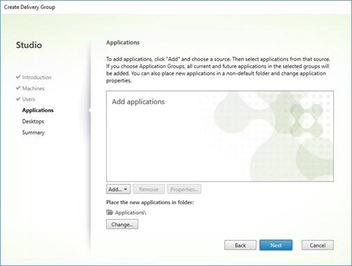
Step 13. Enable Users to access the desktops.
Step 14. Click Next.
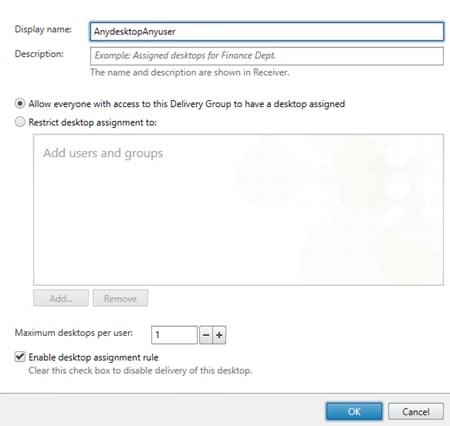
Step 15. On the Summary dialog, review the configuration. Enter a Delivery Group name and a Description (Optional).
Step 16. Click Finish.
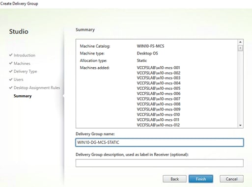
Citrix Studio lists the created Delivery Groups as well as the type, number of machines created, sessions, and applications for each group in the Delivery Groups tab.
Step 17. From the drop-down list, select “Turn on Maintenance Mode.”
Citrix Virtual Apps and Desktops Policies and Profile Management
Policies and profiles allow the Citrix Virtual Apps and Desktops environment to be easily and efficiently customized.
Configure Citrix Virtual Apps and Desktops Policies
Citrix Virtual Apps and Desktops policies control user access and session environments, and are the most efficient method of controlling connection, security, and bandwidth settings. You can create policies for specific groups of users, devices, or connection types with each policy. Policies can contain multiple settings and are typically defined through Citrix Studio.
The Windows Group Policy Management Console can also be used if the network environment includes Microsoft Active Directory and permissions are set for managing Group Policy Objects).
Figure 28 shows the policies for Login VSI testing in this CVD.
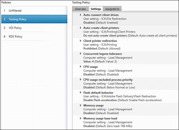
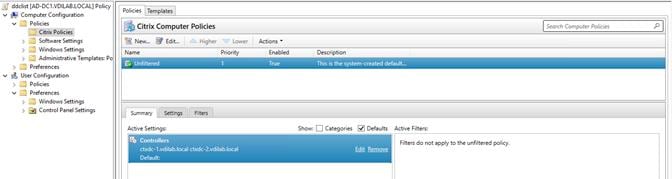
Configure FSLogix
A Windows user profile is a collection of folders, files, registry settings, and configuration settings that define the environment for a user who logs on with a particular user account. These settings may be customizable by the user, depending on the administrative configuration. Profile management in VDI environments is an integral part of the user experience.
FSLogix, a Microsoft tool, was used to manage user profiles in this validated design.
FSLogix allows you to:
● Roam user data between remote computing session hosts
● Minimize sign in times for virtual desktop environments
● Optimize file IO between host/client and remote profile store
● Provide a local profile experience, eliminating the need for roaming profiles.
● Simplify the management of applications and 'Gold Images'
● Additional documentation about the tool can be found here.
Procedure 1. Install FSLogix Apps
Step 1. FSLogix download file here.
Step 2. Run FSLogixAppSetup.exe on VDI master image (32 bit or 64 bit depending on your environment).
Step 3. Click OK to proceed with default installation folder.
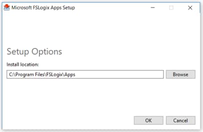
Step 4. Review and accept the license agreement.
Step 5. Click Install.
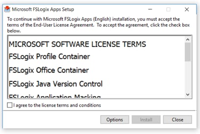
Step 6. Reboot.
Procedure 2. Configure Profile Container Group Policy
Step 1. Copy "fslogix.admx" to C:\Windows\PolicyDefinitions, and "fslogix.adml" to C:\Windows\PolicyDefinitions\en-US on Active Directory Domain Controllers.
Step 2. Create FSLogix GPO as follows and apply to the desktops OU.
Step 3. Navigate to Computer Configuration > Administrative Templates > FSLogix > Profile Containers.
Step 4. Configure the following settings:
● Enabled – Enabled
● VHD location – Enabled, with the path set to \\<FileServer>\<Profiles Directory>
Note: Consider enabling and configuring FSLogix logging as well as limiting the size of the profiles and excluding additional directories.
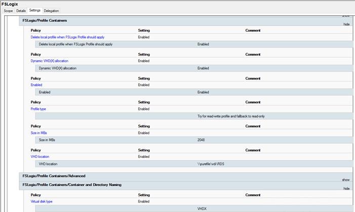
Test Setup, Configuration, and Load Recommendation
This chapter contains the following:
● Cisco UCS Test Configuration for Single Blade Scalability
● Cisco UCS Test Configuration for Full Scale Testing
We tested a single Cisco UCS X210C M7 blade to validate against the performance of one and eight Cisco UCS X210C M7 blades on a single chassis to illustrate linear scalability for each workload use case studied.
Cisco UCS Test Configuration for Single Blade Scalability
This test case validates Recommended Maximum Workload per host server using Citrix Virtual Apps and Desktops 2203 LTSR with 256 Multi-session OS sessions and 200 Single-session OS sessions.
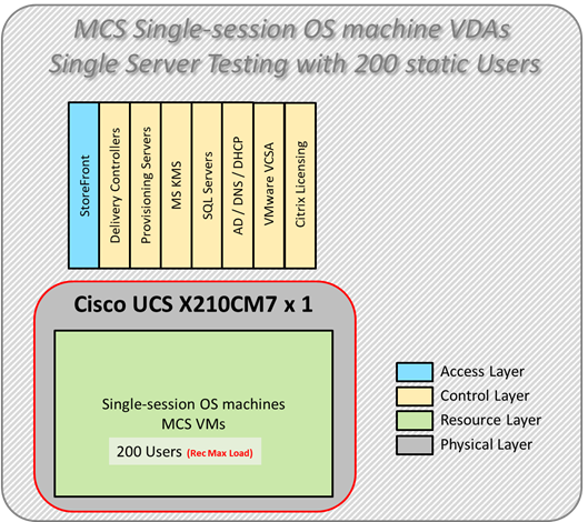
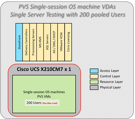
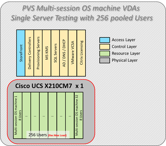
Hardware components:
● Cisco UCSX 9508 Blade Server Chassis
● 2 Cisco UCS 6536 5th Gen Fabric Interconnects
● 1 Cisco UCS X210C M7 Blade Servers with Intel(R) Xeon(R) Gold 6448H CPU 2.4GHz 32-core processors, 2TB 4800MHz RAM for all host blades
● Cisco UCS VIC 15231 CNA (1 per blade)
● 2 Cisco Nexus 93180YC-FX Access Switches
● 2 Cisco MDS 9132T 32-Gb 32-Port Fibre Channel Switches
● Pure Storage FlashArray//X50 R4 with dual redundant controllers, with 20 1.92TB DirectFlash NVMe drives
Software components:
● Cisco UCS firmware
● Infrastructure 4.3(2.240002)
● Cisco UCS X-Series 5.2(0.230127)
● Pure Storage Purity//FA 6.4.10
● ESXi 8.0 Update 2 for host blades
● Citrix Virtual Apps and Desktops 2203 LTSR
● Microsoft SQL Server 2019
● Microsoft Windows 11 64 bit (22H2), 2vCPU, 4 GB RAM, 64 GB HDD (master)
● Microsoft Windows Server 2022 (21H2), 4vCPU, 24GB RAM, 90 GB vDisk (master)
● Microsoft Office 2021 64-bit
● FSLogix 2210 hotfix 3
● Login Enterprise 7.5.2 Knowledge Worker Workload
Cisco UCS Test Configuration for Full Scale Testing
These test cases validate eight blades in a cluster hosting three distinct workloads using Citrix Virtual Apps and Desktops 2203 LTSR with:
● 1400 MCS Single-session OS sessions
● 1400 PVS Single-session OS sessions
● 1800 PVS Multi-session OS sessions
Note: Server N+1 fault tolerance is factored into this solution for each cluster/workload.


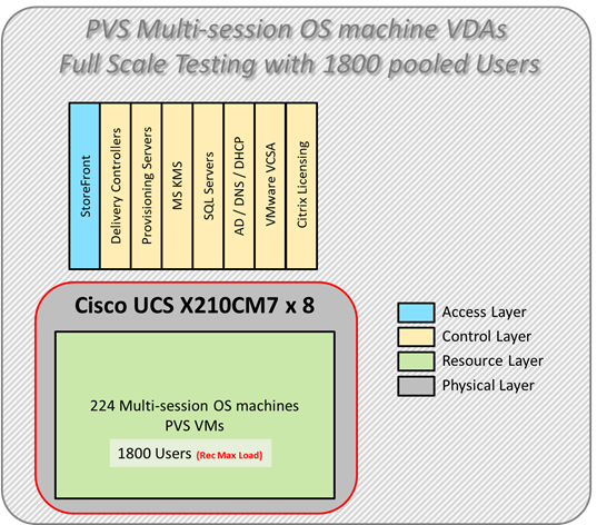
Hardware components:
● Cisco UCSX 9508 Blade Server Chassis
● 2 Cisco UCS 6536 5th Gen Fabric Interconnects
● 8 Cisco UCS X210C M7 Blade Servers with Intel(R) Xeon(R) Gold 6448H CPU 2.4GHz 32-core processors, 2TB 4800MHz RAM for all host blades
● Cisco VIC 1440 CNA (1 per blade)
● 2 Cisco Nexus 93180YC-FX Access Switches
● 2 Cisco MDS 9132T 32-Gb 32-Port Fibre Channel Switches
● Pure Storage FlashArray//X50 R4 with dual redundant controllers, with 20 1.92TB DirectFlash NVMe drives
Software components:
● Cisco UCS firmware
● Infrastructure 4.3(2.240002)
● Cisco UCS X-Series 5.2(0.230127)
● Pure Storage Purity//FA 6.4.10
● ESXi 8.0 Update 2 for host blades
● Citrix Virtual Apps and Desktops 2203 LTSR
● Microsoft SQL Server 2019
● Microsoft Windows 11 64 bit (22H2), 2vCPU, 4 GB RAM, 64 GB HDD (master)
● Microsoft Windows Server 2022 (21H2), 4vCPU, 24GB RAM, 90 GB vDisk (master)
● Microsoft Office 2021 64-bit
● FSLogix 2210 hotfix 3
● Login Enterprise 7.5.2 Knowledge Worker Workload
Test Methodology and Success Criteria
All validation testing was conducted on-site within the Cisco labs in San Jose, California.
The testing results focused on the entire process of the virtual desktop lifecycle by capturing metrics during the desktop boot-up, user logon and virtual desktop acquisition (also referred to as ramp-up,) user workload execution (also referred to as steady state), and user logoff for the RDSH/VDI Session under test.
Test metrics were gathered from the virtual desktop, storage, and load generation software to assess the overall success of an individual test cycle. Each test cycle was not considered passing unless all of the planned test users completed the ramp-up and steady state phases (described below) and unless all metrics were within the permissible thresholds as noted as success criteria.
Three successfully completed test cycles were conducted for each hardware configuration and results were found to be relatively consistent from one test to the next.
You can obtain additional information and a free test license from http://www.loginvsi.com
This chapter contains the following:
● Pre-Test Setup for Single and Multi-Blade Testing
Pre-Test Setup for Single and Multi-Blade Testing
All virtual machines were shut down utilizing the Citrix Studio and vCenter.
All Launchers for the test were shut down. They were then restarted in groups of 10 each minute until the required number of launchers was running with the Login VSI Agent at a “waiting for test to start” state.
All VMware ESXi VDI host blades to be tested were restarted prior to each test cycle.
To simulate severe, real-world environments, Cisco requires the log-on and start-work sequence, known as Ramp Up, to complete in 48 minutes. For testing where the user session count exceeds 1000 users, we will now deem the test run successful with up to 1% session failure rate.
In addition, Cisco performs three consecutive load tests with knowledge worker workload for all single server and scale testing. This assures that our tests represent real-world scenarios. For each of the three consecutive runs on single server tests, the same process was followed. To do so, follow these steps:
Time 0:00:00 Start PerfMon/Esxtop Logging on the following system:
1. vCenter used in the test run.
2. All Infrastructure virtual machines used in test run (AD, SQL, brokers, image mgmt., and so on)
3. Time 0:00:10 Start Storage Partner Performance Logging on Storage System.
4. Time 0:05: Boot Virtual Desktops/RDS Virtual Machines using Citrix Studio.
5. The boot rate should be around 10-12 virtual machines per minute per server.
6. Time 0:06 First machines boot.
7. Time 0:30 Single Server or Scale target number of desktop virtual machines booted on 1 or more blades.
8. No more than 30 minutes for boot up of all virtual desktops is allowed.
9. Time 0:35 Single Server or Scale target number of desktop virtual machines desktops registered in Citrix Studio.
10. Virtual machine settling time.
11. No more than 60 Minutes of rest time is allowed after the last desktop is registered on the Citrix Studio. Typically, a 30-45-minute rest period is sufficient.
12. Time 1:35 Start Login Enterprise Load Test, with Single Server or Scale target number of desktop virtual machines utilizing sufficient number of Launchers (at 20-25 sessions/Launcher).
13. Time 2:23 Single Server or Scale target number of desktop virtual machines desktops launched (48 minute benchmark launch rate).
14. Time 2:25 All launched sessions must become active.
15. Time 2:40 Login Enterprise Load Test Ends (based on Auto Logoff 15 minutes period designated above).
16. Time 2:55 All active sessions logged off.
17. Time 2:57 All logging terminated; Test complete.
18. Time 3:15 Copy all log files off to archive; Set virtual desktops to maintenance mode through broker; Shutdown all Windows machines.
19. Time 3:30 Reboot all hypervisor hosts.
20. Time 3:45 Ready for the new test sequence.
Our pass criteria for this testing is as follows:
● Cisco will run tests at a session count level that effectively utilizes the blade capacity measured by CPU utilization, memory utilization, storage utilization, and network utilization. We will use Login VSI to launch version 4.1.x Office Worker workloads. The number of launched sessions must equal active sessions within two minutes of the last session launched in a test as observed on the VSI Management console.
The Citrix Studio be monitored throughout the steady state to make sure of the following:
● All running sessions report In Use throughout the steady state
● No sessions move to unregistered, unavailable or available state at any time during steady state
● Within 20 minutes of the end of the test, all sessions on all launchers must have logged out automatically and the Login VSI Agent must have shut down. Stuck sessions define a test failure condition.
● Cisco requires three consecutive runs with results within +/-1% variability to pass the Cisco Validated Design performance criteria. For white papers written by partners, two consecutive runs within +/-1% variability are accepted. (All test data from partner run testing must be supplied along with the proposed white paper.)
We will publish Cisco Validated Designs with our recommended workload following the process above and will note that we did not reach a VSImax dynamic in our testing. FlashStack Data Center with Cisco UCS and Citrix Virtual Apps and Desktops 2203 LTSR on VMware ESXi 8.0 Update 2 Test Results.
The purpose of this testing is to provide the data needed to validate VMware Horizon Remote Desktop Sessions (RDS) and VMware Horizon Virtual Desktop (VDI) instant-clones and VMware Horizon Virtual Desktop (VDI) full-clones models using ESXi and vCenter to virtualize Microsoft Windows 11 desktops and Microsoft Windows Server 2022 sessions on Cisco UCS X210C M7 Blade Servers using the Pure Storage FlashArray//X50 R4 storage system.
The information contained in this section provides data points that a customer may reference in designing their own implementations. These validation results are an example of what is possible under the specific environment conditions outlined here, and do not represent the full characterization of VMware products.
Four test sequences, each containing three consecutive test runs generating the same result, were performed to establish single blade performance and multi-blade, linear scalability.
Login VSI helps organizations proactively manage the performance, cost, and capacity of their virtual desktops and applications wherever they reside – traditional, hybrid, or in the cloud. The Login Enterprise platform is 100% agentless and can be used in all major VDI and DaaS environments, including Citrix, VMware, and Microsoft. With 360° proactive visibility, IT teams can plan and maintain successful digital workplaces with less cost, fewer disruptions, and lower risk. Founded in 2012, Login VSI is headquartered in Boston, Massachusetts, and Amsterdam, Netherlands. Visit www.loginvsi.com.
Login Enterprise, by Login VSI, is the industry-standard software used to simulate a human-centric workload used for the purpose of benchmarking the capacity and performance of a VDI solutions. The performance testing documented in this Reference Architecture utilized the Login Enterprise benchmarking tool (https://www.loginvsi.com/platform/). The virtual user technology of Login Enterprise simulates real-world users performing real-world tasks while measuring the time required for each interaction. Login Enterprise assesses desktop performance, application performance, and user experience to determine the overall responsiveness of the VDI solution. Using Login Enterprise for VDI capacity planning helps to determine the optimal hardware configuration to support the desired number of users and applications.
About the EUX Score
The Login Enterprise End-User Experience (EUX) Score is a unique measurement that provides an accurate and realistic evaluation of user experience in virtualized or physical desktop environments. The score is based on metrics that represent system resource utilization and application responsiveness. The results are then combined to produce an overall score between 1 and 10 that closely correlates with the real user experience. See the table below for general performance guidelines with respect to the EUX Score.
| Score |
Assessment |
| Greater than 8.5 |
Excellent |
| 7.5-8.5 |
Very Good |
| 6.5 – 7.5 |
Good |
| 5.5 – 6.5 |
Fair |
| Less than 5.5 |
Poor |
See the following article for more information: https://support.loginvsi.com/hc/en-us/articles/4408717958162-Login-Enterprise-EUX-Score-
About VSImax
The Login Enterprise VSImax is a performance metric used to measure the maximum user capacity or scalability of a virtualized desktop infrastructure (VDI) environment. The EUX Score is used to determine the VSImax, and it represents the maximum number of virtual users that can be supported by the infrastructure while still maintaining acceptable performance levels.
Login Enterprise Workloads
Login Enterprise Workloads are human-centric workloads designed to simulate a user interacting with predetermined applications in a human-paced way. The industry-standard workloads that come with Login Enterprise are Knowledge Worker and Task Worker. These workloads are based on the Microsoft Office suite and popular browsers used in the enterprise. Other workloads are available from Login VSI.
Knowledge worker
An enterprise knowledge worker is a medium to heavy duty productivity user that regularly uses a web browser, an email client, and specializes in a wide range of software to create spreadsheets, documents, and presentations. It is common for knowledge workers to have multiple applications and browsers open at once, regularly switching between these applications. The knowledge worker expects a responsive user experience and has little tolerance for variation in performance.
Task worker
An enterprise task worker is a light duty productivity user that regularly uses a static web browser to access internal sites, an email client and an application that is the basis for their task. Task workers stay focused on the task at hand and switch between apps on occasion. The task worker is tolerant of some workspace lag. Task workers often take the form of data processing workers, call center agents, tellers, and receptionists.
This chapter contains the following:
● Single-Server Recommended Maximum Workload Testing
Single-Server Recommended Maximum Workload Testing
This section shows the key performance metrics that were captured on the Cisco UCS host blades during the single server testing to determine the Recommended Maximum Workload per host server. The single server testing comprised of following tests:
● 200 MCS Single-session OS sessions (Static)
● 200 PVS Single-session OS sessions (Random)
● 256 PVS Multi-session OS sessions (Random)
Single-Server Recommended Maximum Workload for MCS Single-session OS Static Sessions with 200 Users
The recommended maximum workload for a Cisco UCS X210C M7 blade server with dual Intel(R) Xeon(R) Gold 6448H CPU 2.4GHz 32-core processors, 2TB 4800MHz RAM is 200 Windows 11 64-bit persistent MCS virtual machines with 2 vCPU and 4 GB RAM.
Login VSI performance data is shown below.
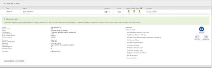
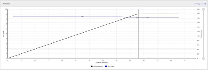
Performance data for the server running the workload is shown below.

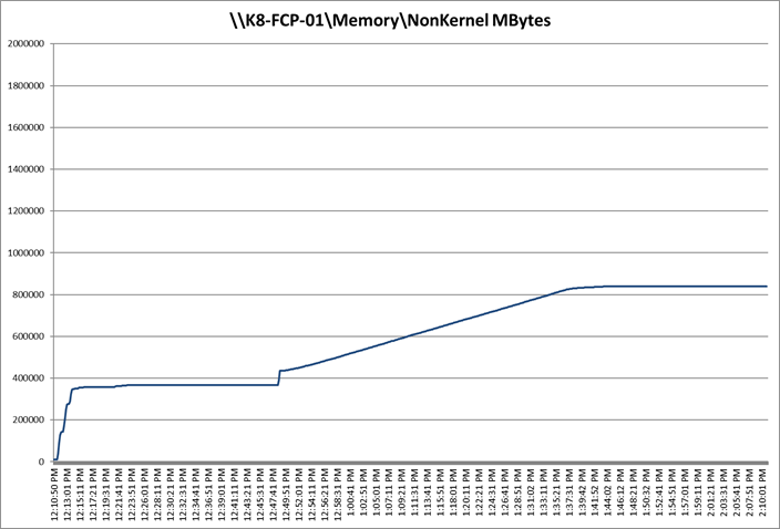
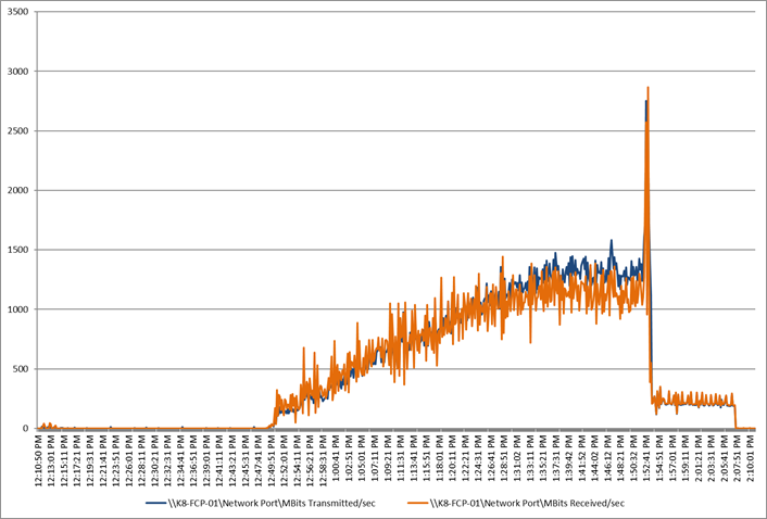
Single-Server Recommended Maximum Workload for PVS Single-session OS Random Sessions with 200 Users
The recommended maximum workload for a Cisco UCS X210C M7 blade server with dual Intel(R) Xeon(R) Gold 6448H CPU 2.4GHz 32-core processors, 2TB 4800MHz RAM is 200 Windows 11 64-bit VDI non-persistent PVS virtual machines with 2 vCPU and 4GB RAM.
Login VSI performance data is as shown below.
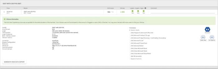
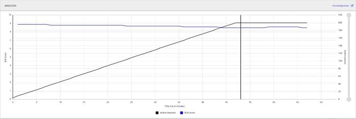
Performance data for the server running the workload is shown below.

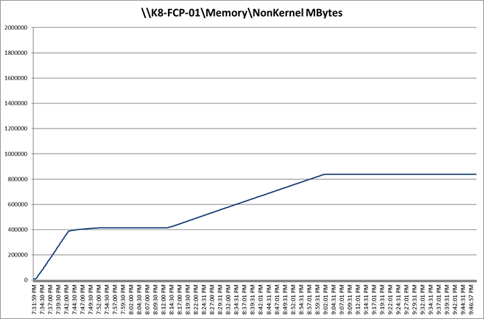
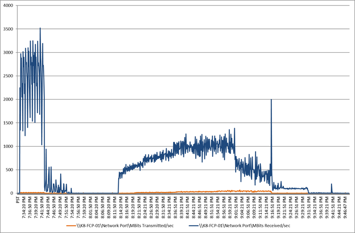
Single-Server Recommended Maximum Workload for PVS Multiple-session OS Random Sessions with 256 Users
The recommended maximum workload for a Cisco UCS X210C M7 blade server with dual Intel(R) Xeon(R) Gold 6448H CPU 2.4GHz 32-core processors, 2TB 4800MHz RAM is 256 Windows Server 2022 sessions. The blade server ran 32 Windows Server 2022 Virtual Machines. Each virtual server was configured with 4 vCPUs and 24GB RAM.
LoginVSI data is shown below.
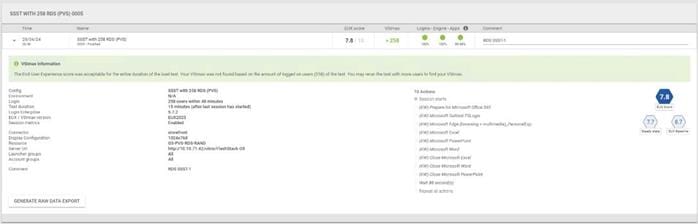
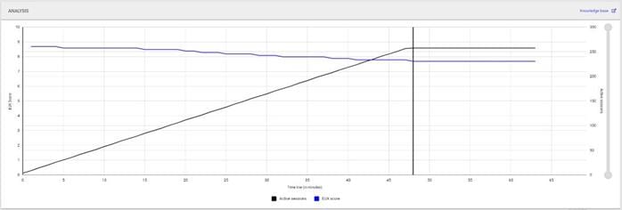
Performance data for the server running the workload is shown below.
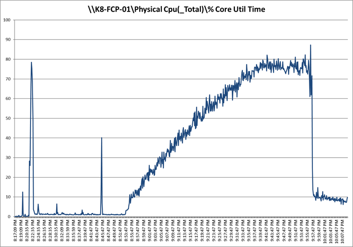
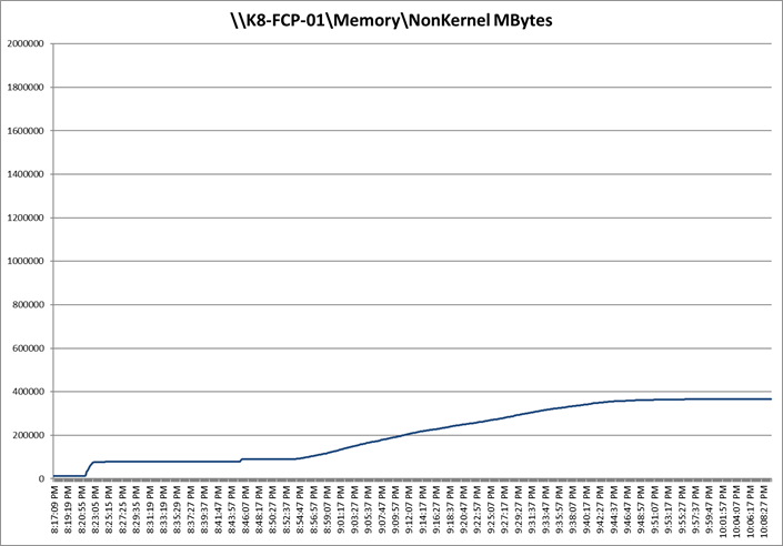
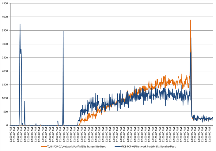
Performance data for the RDS Virtual Machine running the workload is shown below.
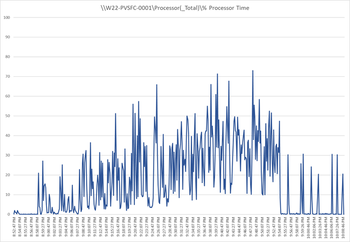
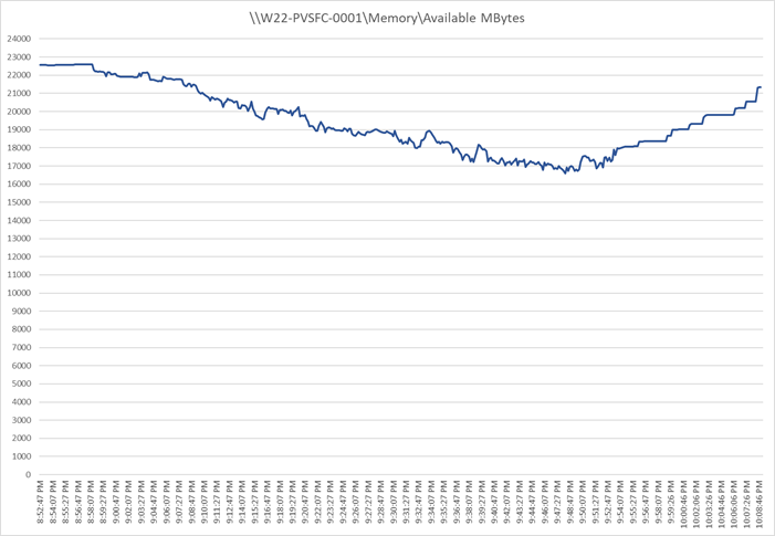
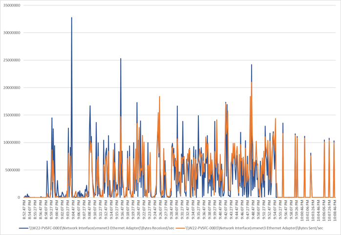
This section describes the key performance metrics that were captured on the Cisco UCS, during the full-scale testing. Full Scale testing was done with following Workloads using 8 Cisco UCS X210C M7 Blade Servers, configured in a single ESXi Host Pool, and designed to support single Host failure (N+1 Fault tolerance):
● 1400 MCS Single-session OS sessions (Static)
● 1400 PVS Single-session OS sessions (Random)
● 1800 MCS Multi-session OS sessions (Random
To achieve the target, sessions were launched against each workload set at a time. As per the Cisco Test Protocol for VDI solutions, all sessions were launched within 48 minutes (using the official Knowledge Worker Workload) and all launched sessions became active within two minutes subsequent to the last logged in session.
Full Scale Recommended Maximum Workload Testing for MCS Single-session OS Machine VDAs with 1400 Users
This section describes the key performance metrics that were captured on the Cisco UCS and Pure Storage FlashArray//X50 R4 array during the full-scale testing with 1400 MCS Single-session OS machines using 8 blades in a single pool.
The workload for the test is 1400 Persistent VDI users. To achieve the target, sessions were launched against all workload hosts concurrently. As per the Cisco Test Protocol for VDI solutions, all sessions were launched within 48 minutes (using the official Knowledge Worker Workload) and all launched sessions became active within two minutes subsequent to the last logged in session.
The configured system efficiently and effectively delivered the following results:
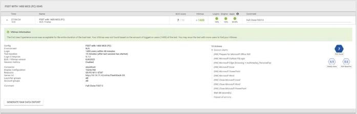
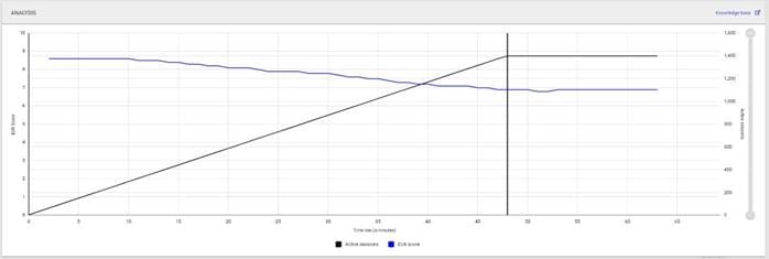

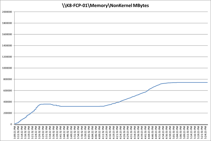
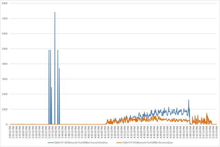
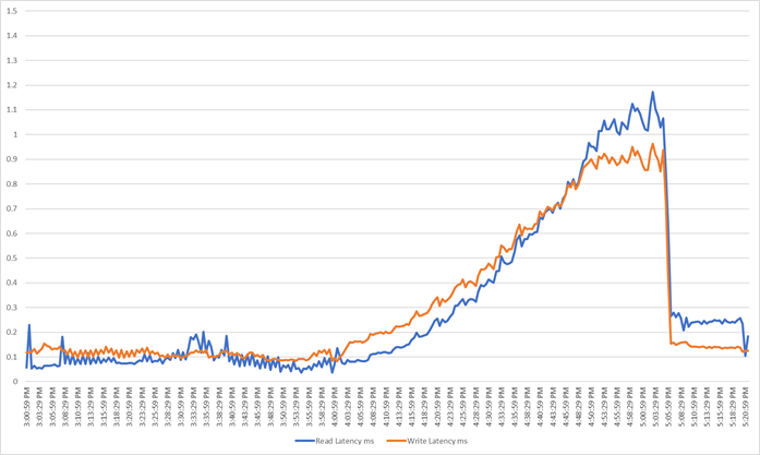
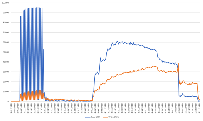
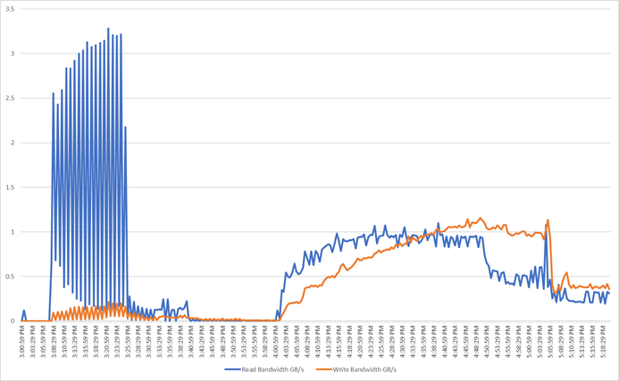
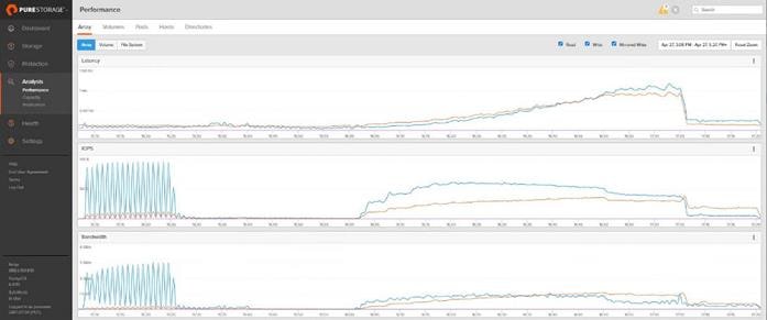
Full Scale Recommended Maximum Workload Testing for PVS Single-session OS Machine VDAs with 1400 Users
This section describes the key performance metrics that were captured on the Cisco UCS and Pure Storage FlashArray during the persistent desktop full-scale testing with 1400 PVS Single-session OS machines using 8 blades in a single pool.
The workload for the test is 1400 Non-Persistent VDI users. To achieve the target, sessions were launched against all workload clusters concurrently. As per the Cisco Test Protocol for VDI solutions, all sessions were launched within 48 minutes (using the official Knowledge Worker Workload in VSI Benchmark Mode) and all launched sessions became active within two minutes subsequent to the last logged in session.
The configured system efficiently and effectively delivered the following results:

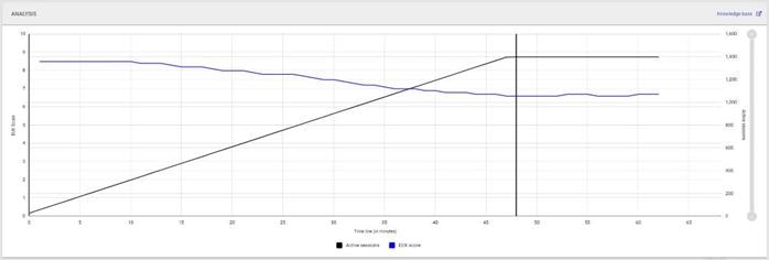

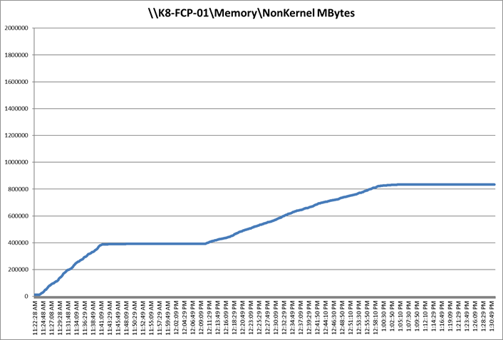
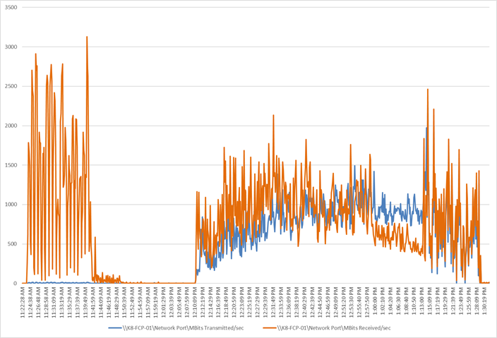
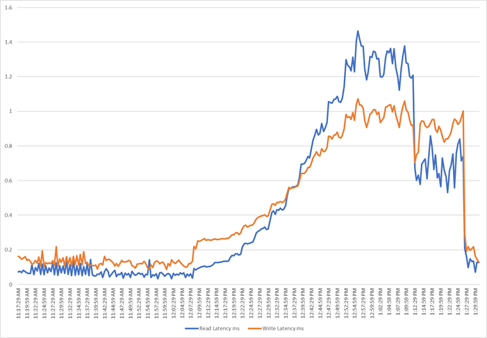
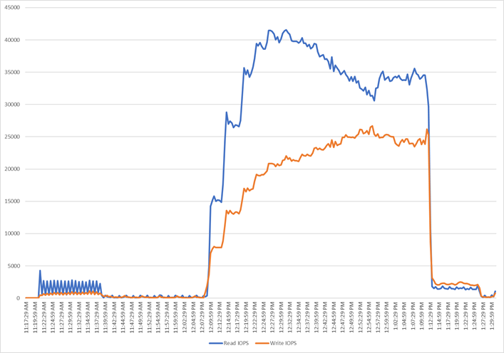
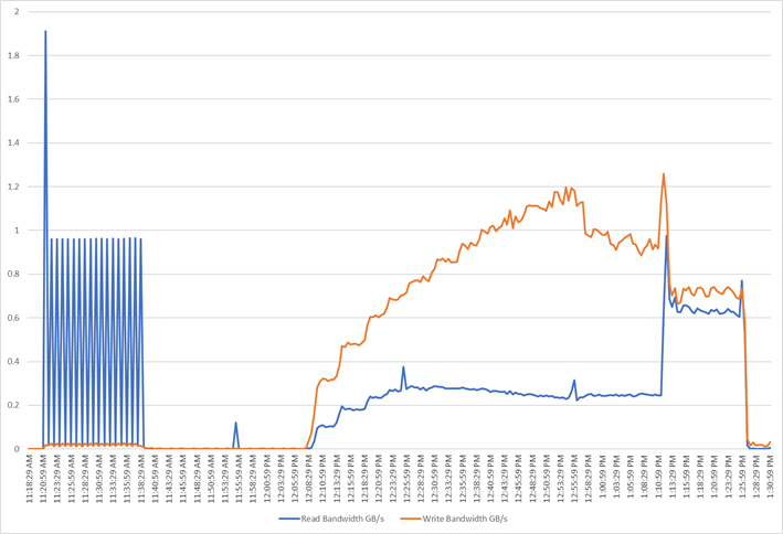
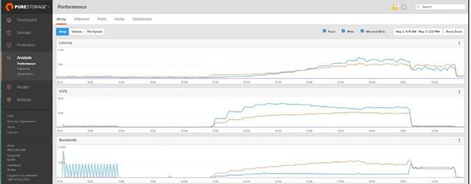
Full Scale Recommended Maximum Workload for PVS Multi-session OS Random Sessions with 1800 Users
This section describes the key performance metrics that were captured on the Cisco UCS and Pure Storage FlashArray//X50 R4 array, during the PVS Multi-session OS full-scale testing with 1800 Desktop Sessions using 8 blades configured in single Host Pool.
The Multi-session OS workload for the solution is 1800 users. To achieve the target, sessions were launched against all workload clusters concurrently. As per the Cisco Test Protocol for VDI solutions, all sessions were launched within 48 minutes (using the official Knowledge Worker Workload) and all launched sessions became active within two minutes subsequent to the last logged in session.
The configured system efficiently and effectively delivered the following results:
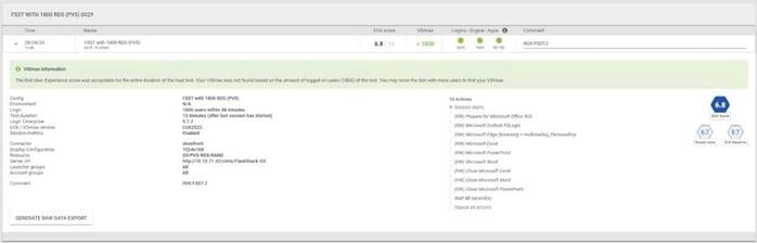
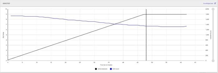

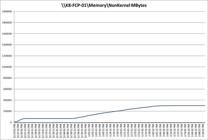
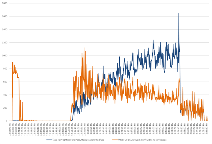
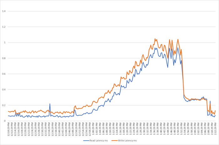
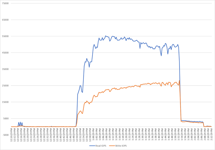
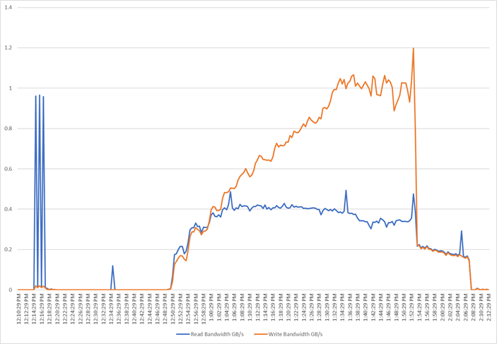
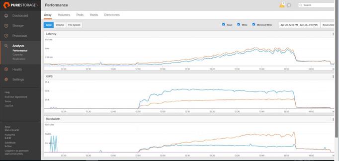
FlashStack is a powerful and reliable platform that has been specifically developed for enterprise end-user computing deployments and cloud data centers. It utilizes a range of innovative technologies, including Cisco UCS Blade and Rack Servers, Cisco Fabric Interconnects, Cisco Nexus 9000 switches, Cisco MDS 9100 Fibre Channel switches, and Pure Storage FlashArray//50 Storage Array, to provide you with a comprehensive solution that is designed and validated using best practices for compute, network, and storage.
With the introduction of Cisco UCS X210c M7 Series modular platform and Cisco Intersight, FlashStack now offers even more benefits for you. These technologies enhance the ability to provide complete visibility and orchestration across all elements of the FlashStack datacenter, enabling you to modernize your infrastructure and operations. This means you can achieve higher levels of efficiency, scalability, and flexibility while also reducing deployment time, project risk, and IT costs.
FlashStack has been validated using industry-standard benchmarks to ensure that it meets the highest standards of performance, management, scalability, and resilience. This makes it the ideal choice for those who are looking to deploy enterprise-class VDI and other IT initiatives. With its powerful combination of hardware and software, FlashStack is capable of meeting the demands of the most complex and demanding IT environments, ensuring that you can focus on your core business objectives without having to worry about the underlying infrastructure.
Get More Business Value with Services
Whether you are planning your next-generation environment, need specialized know-how for a major deployment, or want to get the most from your current storage, Cisco Advanced Services, Pure Storage FlashArray//50 storage and our certified partners can help. We collaborate with you to enhance your IT capabilities through a full portfolio of services for your IT lifecycle with:
● Strategy services to align IT with your business goals.
● Design services to architect your best storage environment.
● Deploy and transition services to implement validated architectures and prepare your storage environment.
● Operations services to deliver continuous operations while driving operational excellence and efficiency.
Additionally, Cisco Advanced Services and Pure Storage Support provide in-depth knowledge transfer and education services that give you access to our global technical resources and intellectual property.
This appendix contains the following:
● Full Scale Server Performance Charts
Full Scale Server Performance Charts
This section provides a detailed performance chart for ESXi 8.0 Update 2 installed on Cisco UCS X210C M7 Blade Server as part of the workload test with Citrix Virtual Apps and Desktops 2203 LTSR deployed on Pure Storage FlashArray//50 R4 system running Login Enterprise 7.5.2 based knowledge worker workload part of the FlashStack reference architecture defined here.
The charts below are defined in the set of 8 hosts in the single performance chart.
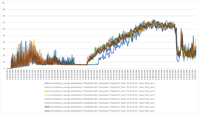
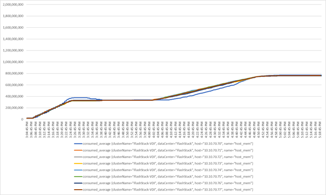
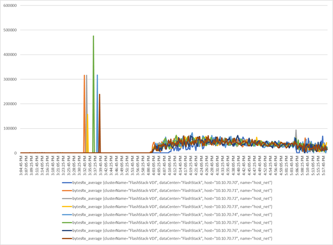
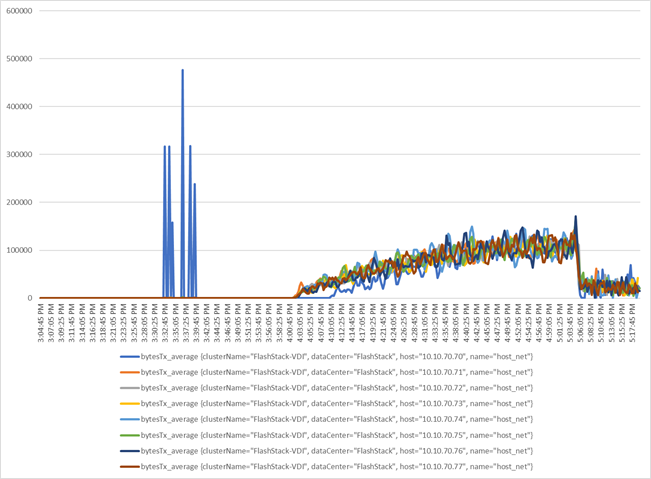
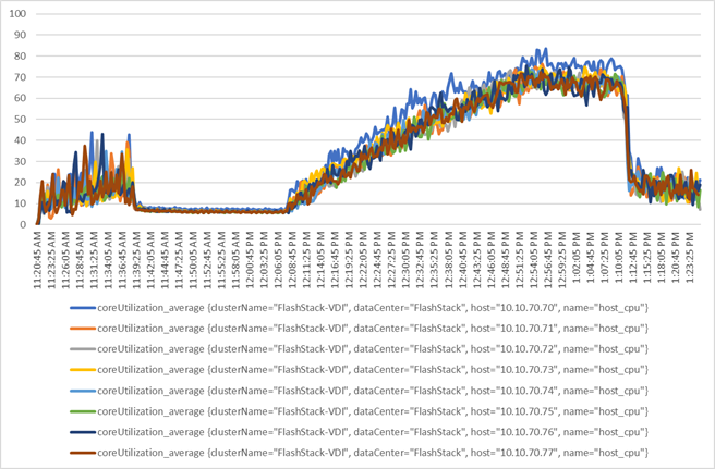
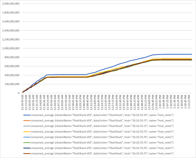
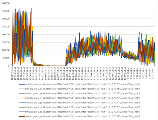
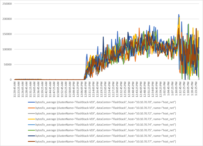
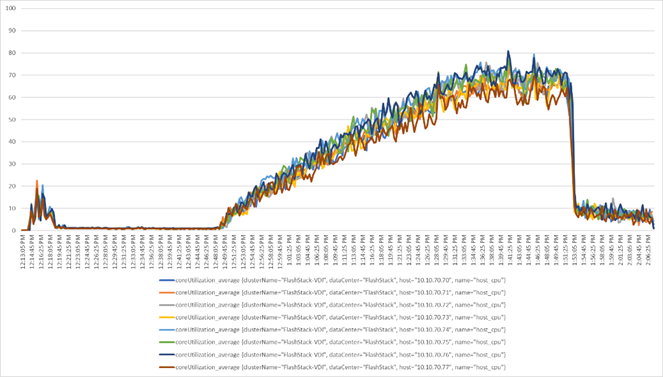
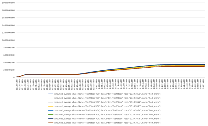
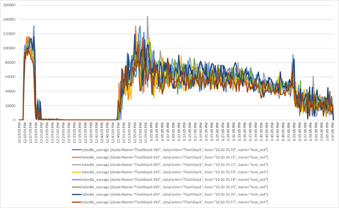
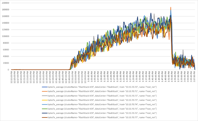
Table 21 provides a parts list.
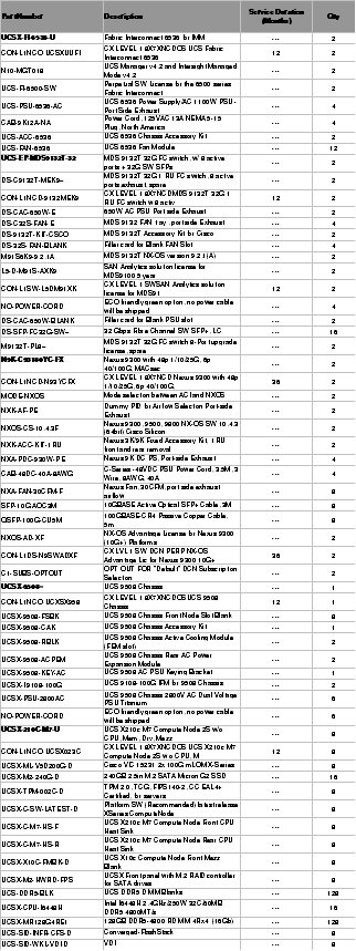
Feedback
For comments and suggestions about this guide and related guides, join the discussion on Cisco Community at https://cs.co/en-cvds.
ALL DESIGNS, SPECIFICATIONS, STATEMENTS, INFORMATION, AND RECOMMENDATIONS (COLLECTIVELY, "DESIGNS") IN THIS MANUAL ARE PRESENTED "AS IS," WITH ALL FAULTS. CISCO AND ITS SUPPLIERS DISCLAIM ALL WARRANTIES, INCLUDING, WITHOUT LIMITATION, THE WARRANTY OF MERCHANTABILITY, FITNESS FOR A PARTICULAR PURPOSE AND NONINFRINGEMENT OR ARISING FROM A COURSE OF DEALING, USAGE, OR TRADE PRACTICE. IN NO EVENT SHALL CISCO OR ITS SUPPLIERS BE LIABLE FOR ANY INDIRECT, SPECIAL, CONSEQUENTIAL, OR INCIDENTAL DAMAGES, INCLUDING, WITHOUT LIMITATION, LOST PROFITS OR LOSS OR DAMAGE TO DATA ARISING OUT OF THE USE OR INABILITY TO USE THE DESIGNS, EVEN IF CISCO OR ITS SUPPLIERS HAVE BEEN ADVISED OF THE POSSIBILITY OF SUCH DAMAGES.
THE DESIGNS ARE SUBJECT TO CHANGE WITHOUT NOTICE. USERS ARE SOLELY RESPONSIBLE FOR THEIR APPLICATION OF THE DESIGNS. THE DESIGNS DO NOT CONSTITUTE THE TECHNICAL OR OTHER PROFESSIONAL ADVICE OF CISCO, ITS SUPPLIERS OR PARTNERS. USERS SHOULD CONSULT THEIR OWN TECHNICAL ADVISORS BEFORE IMPLE-MENTING THE DESIGNS. RESULTS MAY VARY DEPENDING ON FACTORS NOT TESTED BY CISCO.
CCDE, CCENT, Cisco Eos, Cisco Lumin, Cisco Nexus, Cisco StadiumVision, Cisco TelePresence, Cisco WebEx, the Cisco logo, DCE, and Welcome to the Human Network are trademarks; Changing the Way We Work, Live, Play, and Learn and Cisco Store are service marks; and Access Registrar, Aironet, AsyncOS, Bringing the Meeting To You, Catalyst, CCDA, CCDP, CCIE, CCIP, CCNA, CCNP, CCSP, CCVP, Cisco, the Cisco Certified Internetwork Expert logo, Cisco IOS, Cisco Press, Cisco Systems, Cisco Systems Capital, the Cisco Systems logo, Cisco Unified Computing System (Cisco UCS), Cisco UCS B-Series Blade Servers, Cisco UCS C-Series Rack Servers, Cisco UCS S-Series Storage Servers, Cisco UCS X-Series, Cisco UCS Manager, Cisco UCS Management Software, Cisco Unified Fabric, Cisco Application Centric Infrastructure, Cisco Nexus 9000 Series, Cisco Nexus 7000 Series. Cisco Prime Data Center Network Manager, Cisco NX-OS Software, Cisco MDS Series, Cisco Unity, Collaboration Without Limitation, EtherFast, EtherSwitch, Event Center, Fast Step, Follow Me Browsing, FormShare, GigaDrive, HomeLink, Internet Quotient, IOS, iPhone, iQuick Study, LightStream, Linksys, MediaTone, MeetingPlace, MeetingPlace Chime Sound, MGX, Networkers, Networking Academy, Network Registrar, PCNow, PIX, PowerPanels, ProConnect, ScriptShare, SenderBase, SMARTnet, Spectrum Expert, StackWise, The Fastest Way to Increase Your Internet Quotient, TransPath, WebEx, and the WebEx logo are registered trade-marks of Cisco Systems, Inc. and/or its affiliates in the United States and certain other countries. (LDW_P1)
All other trademarks mentioned in this document or website are the property of their respective owners. The use of the word partner does not imply a partnership relationship between Cisco and any other company. (0809R)