FlexPod Datacenter Zero Trust Framework
Available Languages
Bias-Free Language
The documentation set for this product strives to use bias-free language. For the purposes of this documentation set, bias-free is defined as language that does not imply discrimination based on age, disability, gender, racial identity, ethnic identity, sexual orientation, socioeconomic status, and intersectionality. Exceptions may be present in the documentation due to language that is hardcoded in the user interfaces of the product software, language used based on RFP documentation, or language that is used by a referenced third-party product. Learn more about how Cisco is using Inclusive Language.
- US/Canada 800-553-2447
- Worldwide Support Phone Numbers
- All Tools
 Feedback
 Feedback

![]()
In partnership with:

About the Cisco Validated Design Program
The Cisco Validated Design (CVD) program consists of systems and solutions designed, tested, and documented to facilitate faster, more reliable, and more predictable customer deployments. For more information, go to: http://www.cisco.com/go/designzone.
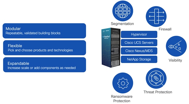
The FlexPod Datacenter solution is a validated approach for deploying Cisco® and NetApp technologies and products to build shared private and public cloud infrastructure. Cisco and NetApp have partnered to deliver a series of FlexPod solutions that enable strategic data-center platforms. The success of the FlexPod solution is driven by its ability to evolve and incorporate both technology and product innovations in the areas of management, computing, storage, networking, and security. This document explains the deployment details of incorporating and implementing various tools, technologies, and products to deliver a Zero Trust security framework for FlexPod Datacenter.
FlexPod delivers an integrated architecture that incorporates compute, storage, and network design best practices, thereby minimizing IT risks by validating the integrated architecture to ensure compatibility between various components. The solution also addresses IT pain points by providing documented design guidance, deployment guidance, and support that can be used in various stages (planning, designing, and implementation) of a deployment.
FlexPod Datacenter delivers following key benefits:
● Simpler and programmable infrastructure: FlexPod infrastructure delivered as infrastructure-as-code through a single partner integrable open API.
● Latest hardware and software compute innovations: policy-based configurations, delivered using Cisco Intersight, to deploy and manage the latest processor, memory, network, and power/cooling improvements.
● Storage Modernization: deliver high-speed, consistent, low latency, multi-tenant storage using a range of NetApp storage arrays.
● Innovative cloud operations: continuous feature delivery and no need for maintaining on-premises physical or virtual machines supporting management functions.
● Built for investment protections: design ready for future compute technologies such as liquid cooling and high-Wattage CPUs; CXL-ready.
A Zero Trust security framework is a comprehensive approach to network security that assumes no user, system, or device can be trusted by default, regardless of its location relative to the network perimeter. It operates under the principle of "never trust, always verify," meaning that every access request is thoroughly verified before granting access, irrespective of where it originates from. The Zero Trust framework aims to protect modern digital environments by leveraging network segmentation, preventing lateral movement, providing Layer 7 threat prevention, and simplifying granular user-access control.
Implementing Zero Trust framework on a FlexPod infrastructure provides following additional benefits:
● Enhanced Security: By treating every access request as a potential threat, Zero Trust significantly reduces the risk of data breaches and other security incidents.
● Greater Visibility: Constant monitoring of network activities provides a comprehensive view of the network, enabling quick identification and response to any unusual or suspicious activities.
● Reduced Attack Surface: By enforcing least privilege access and micro-segmentation, Zero Trust minimizes the potential points of vulnerability in the network.
● Improved Compliance: The stringent security controls in Zero Trust can help organizations meet compliance requirements for data protection and privacy.
● Efficient Incident Response: Quickly detect, block, and respond to threats. Verify data integrity and implement data loss prevention.
● Protection Against Internal Threats: Zero Trust considers the possibility of threats coming from inside the network, offering protection against insider threats as well as external ones.
The Zero Trust framework for FlexPod solution incorporates various additional security components by Cisco and NetApp including Cisco Secure Firewall Threat Defense (FTD), Cisco Secure Network Analytics (previously Stealthwatch), Cisco Secure Workload (previously Tetration), and NetApp Autonomous Ransomware Protection (ARP).
If you’re interested in understanding the FlexPod design and deployment details, including the configuration of various elements of design and associated best practices, see Cisco Validated Designs for FlexPod: https://www.cisco.com/c/en/us/solutions/design-zone/data-center-design-guides/flexpod-design-guides.html.
Solution Overview
This chapter contains the following:
● Audience
● Platform Resilience: device and protocol hardening including traffic isolation, role-based access control (RBAC), and utilizing secure connectivity.
● Segmentation and Control: multi-tenancy design using virtual routing and forwarding (VRF), VLANs, and Cisco Firewall Threat Defense.
● Visibility and Monitoring: network and OS level visibility and anomaly detection using Cisco Secure Network Analytics and Cisco Secure Workload.
● Threat Protection and Response: controlling the breach and recover quickly using Cisco Secure Workload and NetApp Ransomware Protection.
The intended audience of this document includes but is not limited to IT architects, sales engineers, field consultants, professional services, IT managers, partner engineering, and customers who want to take advantage of an infrastructure built to deliver IT efficiency and enable IT innovation.
This document provides deployment guidance around incorporating the Zero Trust framework design principles in a FlexPod Datacenter environment. This document provides deployment steps for the following key areas:
● Preparing a base FlexPod infrastructure to be used in the solution.
● Setting up infrastructure, network, compute, storage, and virtualization, for secure segmentation.
● Deploying Cisco Secure Firewall Threat Defense virtual (FTDv) to protect the tenant traffic and Cisco Secure Firewall Management Center (FMC) to manage multiple tenant firewalls.
● Deploying Cisco Secure Network Analytics virtual and enabling NetFlow on various points in the network for visibility.
● Setting up Intel Confidential Computing components to enable Intel Total Memory Encryption (TME) and Intel Software Guard Extensions (SGX).
● Using a two-tier model application, WordPress, demonstrate the application and virtual machines (VMs) control using Cisco Secure Workload (SaaS).
● Setup and utilize NetApp Autonomous Ransomware Protection (ARP) to recover a compromised application.
This document augments the FlexPod Datacenter using IaC with Cisco IMM M7, VMware vSphere 8, and NetApp ONTAP 9.12.1 (CVD) and explains new and changed information to support Zero Trust framework deployment.
The following design elements distinguish this FlexPod Datacenter Cisco Validated Design from previous designs:
● Enhanced platform security.
● Multi-tenant design.
● Controlling data traffic between various tenants using Cisco Secure Firewall Threat Defense virtual (FTDv).
● Cisco Secure Network Analytics virtual for network and process level visibility.
● Cisco Secure Workload SaaS for threat protections, application and VM control.
● Deployment of Intel Confidential Computing elements.
● Data loss prevention using NetApp Autonomous Ransomware Protection.
Deployment Hardware and Software
This chapter contains the following:
The Zero Trust framework for FlexPod Datacenter design incorporates various security products and components providing a robust framework that extends to all layers, including network, compute, hypervisor, and storage and includes implementation of tenant-based segmentation. This FlexPod validated design includes the following:
● Cisco Secure Firewall Threat Defense virtual devices are utilized to ensure secure communication across application tiers and tenants.
● Intel Confidential Computing provides a secure environment to execute customer workloads.
● Cisco Secure Network Analytics combined with NetFlow export from various sources provide application and tenant visibility.
● Cisco Secure Workload is used for visibility into workload VMs' OS and processes and for providing micro segmentation.
● NetApp Autonomous Ransomware Protection delivers data classification, protection, and recovery. Additionally, data isolation on NetApp is achieved using IPspaces and Storage Virtual Machines (SVMs).
The FlexPod Datacenter with Cisco UCS and Cisco Intersight meets the following general design requirements:
● Resilient design across all layers of the infrastructure with no single point of failure.
● Scalable design with the flexibility to add compute capacity, storage, or network bandwidth as needed.
● Modular design that can be replicated to expand and grow as the needs of the business grow.
● Flexible design that can support different models of various components with ease.
● Simplified design with ability to integrate and automate with external automation tools.
● Cloud-enabled design which can be configured, managed, and orchestrated from the cloud using GUI or APIs.
● Follow cybersecurity best practices including device and protocol hardening therefore reducing the risk of configuration errors and vulnerabilities.
● Reduce attack surface using designs that support enhanced segmentation and control and reduce attack surface for malicious actors.
● Continuous Monitoring of the infrastructure at every layer to identify and mitigate threats.
● Utilize tools that allow for centralized device and security management and policy enforcement.
To deliver a solution which meets all these design requirements, various solution components are connected in a FlexPod configuration as shown in Figure 2. The deployment details are covered in the upcoming sections.
The Zero Trust framework for FlexPod can be deployed on both Fibre Channel (FC) and IP-based storage access FlexPod designs. For the FC designs, NetApp AFF A400 and Cisco UCS X-Series are connected through Cisco MDS 9132T Fibre Channel Switches and boot from SAN for stateless compute and uses the FC network. For the IP-only solution, there is no FC network and Cisco MDS is not needed. The boot from SAN for stateless compute uses the iSCSI network.
Note: The Fibre Channel based FlexPod design is supported but was not validated as part of this effort.
FlexPod Configuration
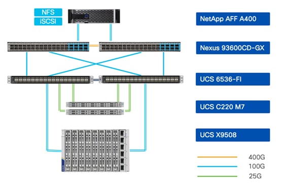
The FlexPod physical topology used in this deployment guide is shown in Figure 3.
Note: The validated configuration showcases the Cisco UCS X-Series chassis and Cisco UCS M7 servers. The Cisco UCS B-Series chassis and Cisco UCS B200 M6 servers were not validated in this CVD but are also supported.
The components are setup as follows:
● Cisco Nexus 93600CD-GX Switches in Cisco NX-OS mode provide the switching fabric. The two Nexus switches connect to each other using two 400Gbps ports configured as a port-channel (VPC peer-link).
● Cisco UCS 6536 Fabric Interconnects provide the Cisco UCS X-Series chassis, Cisco UCS C-Series servers, and network switch connectivity:
◦ Cisco UCS 6536 Fabric Interconnect (FI) 100 Gigabit Ethernet uplink ports connect to Cisco Nexus 93600CD-GX Switches in a vPC configuration.
◦ Cisco UCS X9508 Chassis connects to Cisco UCS 6536 FIs using Cisco UCSX 9108-100G Intelligent Fabric Modules (IFMs), where two or more 100 Gigabit Ethernet ports are used on each IFM to connect to the appropriate FI.
◦ The Cisco UCS C220 M7 servers connect to Cisco UCS 6536 FIs using four 25G connections. 100G to 4x25G breakout cables are used for this connectivity. Cisco UCS C220 M7 servers can also connect to UCS Fabric Interconnect using 100G VIC adapters.
◦ Cisco UCS x210c M7 compute nodes contain fifth-generation Cisco UCS 15231 virtual interface cards.
◦ Cisco UCS C220 M7 servers contain fifth-generation Cisco UCS 15428 virtual interface cards.
● The NetApp AFF A400 controller connects to the Cisco Nexus 93600CD-GX Switches using two 100 GE ports from each controller configured as a vPC for iSCSI boot and for NFS traffic.
● VMware 7.0 Update 3 ESXi software is installed on Cisco UCS compute nodes and rack servers.
VLAN Configuration
Table 1 lists VLANs configured for setting up the environment along with their usage.
| VLAN ID |
Name |
Description |
Subnet |
| 2 |
Native-VLAN |
Use VLAN 2 as native VLAN instead of default VLAN (1) |
|
| 1230 |
Mgmt |
Existing out of band management VLAN. |
10.123.0.0/24 |
| 1231 |
IB-Mgmt |
FlexPod In-band management VLAN. |
10.123.1.0/24 |
| 1232 |
Traffic-VLAN |
VLAN for all Firewall Thread Defense Virtual (FTDv) outside instances. |
10.123.2.0/24 |
| 3000 |
Infra-vMotion |
vMotion VLAN for all the infrastructure ESXi hosts |
10.101.7.0/24 |
| 3001 |
Infra-iSCSI-A |
Infrastructure host iSCSI-A VLAN |
192.168.1.0/24 |
| 3002 |
Infra-iSCSI-B |
Infrastructure host iSCSI-B VLAN |
192.168.2.0/24 |
| 3003 |
Infra-NFS |
VLAN for ESXi NFS datastore to host all VMs |
192.168.3.0/24 |
| 301-305 |
Tenant<x>-Inside |
VLANs for inside interfaces of FTDv appliances. The number of VLANs will depend on the number of tenants. |
172.21.<x>.0/24 |
| 3301-3305 |
Tenant<x>-NFS |
VLANs for Tenant SVM specific NFS network |
172.22.<x>.0/24 |
Some of the key highlights of VLAN usage are as follows:
● VLAN 1230 is the management VLAN where out of band management interfaces of all the physical devices are connected.
● VLAN 1231 is used for in-band management of VMs, ESXi hosts, and other infrastructure services such as DNS, AD, etc. in the FlexPod environment.
● VLAN 1232 is used for outside Interface of all the tenant FTDv appliances. You can choose to deploy separate VLANs, one for every FTDv, for more granular control.
● VLAN 3000 is the VM vMotion VLAN for infrastructure ESXi hosts.
● VLAN 3001 is used by infrastructure ESXi hosts to access iSCSI boot LUNs (A-Path).
● VLAN 3002 is also used by infrastructure ESXi hosts to access iSCSI boot LUNs (B-Path).
● VLAN 3003 provides ESXi hosts access to the infrastructure NSF datastores hosted on the NetApp Controllers. Infrastructure NFS storage is used as primary storage to host all the Tenant VMs in this design.
● VLANs 301+ are used for inside interfaces of all the FTDv. Each tenant will use a separate inside VLAN for traffic segregation. These protected VLANs will also be used for defining NetApp SVM management interfaces.
● VLANs 3301+ are used to provide NFS access to per-tenant Storage Virtual Machines (SVMs). Separate VLANs keep the traffic segregated. These VLANs are not needed if tenants do not require access to dedicated NFS shares.
Physical Components
Table 2 lists the required hardware components used to build the validated solution. You are encouraged to review your requirements and adjust the size or quantity of various components as needed.
| Component |
Hardware |
Comments |
| Cisco Nexus Switches |
Two Cisco Nexus 93600CD-GX switches |
|
| NetApp AFF A400 |
A NetApp AFF A400 HA pair with appropriate storage and network connectivity |
Your requirements will determine the amount of storage. The NetApp A400 should support 100Gbps (or 25 Gbps) ethernet connectivity |
| Fabric Interconnects |
Two Cisco UCS 6536 Fabric Interconnects |
These fabric interconnects provide connectivity for X-Series chassis and C-Series rack servers |
| Cisco UCS Chassis |
A minimum of one UCS X9508 chassis. |
Single chassis can host up to 8 Cisco UCS X210c M6/M7 compute nodes or a combination of compute and X440p PCIe GPU nodes |
| Cisco UCS Compute Nodes |
A total of four or more servers in any combination |
The validated configuration comprised of 2 X210c M7 compute nodes and 2 C220 M7 rack servers |
Table 3 lists various software releases used in the solution.
Table 3. Software Components and Versions
| Component |
Version |
| Cisco Nexus 93600CD-GX |
10.2(6) |
| Cisco UCS FI 6536 |
4.3(2) |
| Cisco UCS C220 M7 |
4.2(2a) |
| Cisco UCS X210c compute nodes |
5.2(0) |
| NetApp A400 - ONTAP |
9.13.1 |
| NetApp Active IQ Unified Manager |
9.13 |
| NetApp ONTAP Tools for VMware vSphere |
9.13 |
| NetApp SnapCenter Plugin for VMware vSphere |
4.9 |
| VMware vCenter |
7.0 Update 3 |
| VMware ESXi |
7.0 Update 3 |
| Security and Visibility |
|
| Cisco Secure Network Analytics |
7.4.2 |
| Cisco Secure Firewall Threat Defense |
7.2.5 |
| Cisco Secure Firewall Management Center |
7.2.5 |
| Cisco Secure Workload (SaaS) |
3.9.1.1* |
* Secure Workload SaaS version is automatically updated.
Setting up the base FlexPod Infrastructure
This chapter contains the following:
● Network Switch Configuration
● NetApp ONTAP Storage Configuration
● Cisco Intersight Managed Mode Configuration
● Storage Configuration – ONTAP Boot Storage Setup
● Storage Configuration – ONTAP NVMe Configuration and Finalizing ONTAP Storage
● FlexPod Management Tools Setup
The configuration procedures of the base FlexPod Infrastructure are similar to those from the FlexPod Datacenter using IaC with Cisco IMM M7, VMware vSphere 8, and NetApp ONTAP 9.12.1 CVD with the following main differences due to the deployed configurations.
● This solution validation configuration uses an IP-only solution topology and Cisco MDS switches are therefore not needed. The SAN boot stateless compute uses iSCSI protocol and ethernet network switching infrastructure.
● The VLAN IDs used in this CVD are listed in Table 1 and should be used when following the setup procedures.
● The revisions of the infrastructure component software, as listed in Table 3, are different:
◦ Cisco UCS - 4.3(2) instead of 4.2(3d).
◦ Cisco Nexus switches - 10.2(6) instead of 10.2(5M).
◦ NetApp ONTAP - 9.13.1 instead of 9.12.1.
● The revisions of the infrastructure management software are different:
◦ NetApp Active IQ Unified Manager - 9.13 instead of 9.12.
◦ NetApp ONTAP Tools for VMware vSphere - 9.13 instead of 9.12.
◦ NetApp SnapCenter Plugin for VMware vSphere - 4.9 instead of 4.8.
◦ VMware vCenter - 7.0U3 instead of 8.0.
◦ VMware ESXi - 7.0U3 instead of 8.0.
● The deployment of additional components as needed for Zero Trust framework:
◦ Cisco Secure Network Analytics - 7.4.2.
◦ Cisco Secure Firewall Thread Device Virtual - 7.2.5.
◦ Cisco Secure Firewall Management Center - 7.2.5.
◦ Cisco Secure Workload SaaS - 3.9.1.1
The required network switch configuration for the base FlexPod infrastructure follows the base CVD section linked below. The Cisco Nexus 9000 series switch featured in this validation is the Cisco Nexus 93600CD-GX configured in NX-OS standalone mode running 10.2(6) firmware. Although different switches and firmware versions are used compared to the based CVD, the same configuration procedures apply. The VLAN IDs used during this CVD are listed in Table 1 and should be adjusted according to your environment.
For more information, see FlexPod Datacenter using IaC with Cisco IMM M7, VMware vSphere 8, and NetApp ONTAP 9.12.1, section Network Switch Configuration. This section provides the switch configuration for the infrastructure tenant. Additional configurations for the tenant deployment are explained in a following section.
NetApp ONTAP Storage Configuration
The required initial NetApp ONTAP storage configuration follows the CVD section here: NetApp ONTAP Storage Configuration. This section provides the initial ONTAP storage configuration for the infrastructure tenant. Additional ONTAP storage configurations for multi-tenant deployment are explained in a following section. The NetApp AFF A-series storage featured in this validation is the NetApp AFF A400 running ONTAP 9.13.1 in IP-based solution configuration. Although a newer ONTAP version is available, the same configuration procedures apply.
Cisco Intersight Managed Mode Configuration
Cisco Intersight managed mode standardizes policy and operation management for the Cisco UCS X210c M7 compute nodes and Cisco UCS C220 M7 rack servers used in this deployment. The required Cisco Intersight Managed Mode configuration follows the base CVD section here: Cisco Intersight Managed Mode Configuration. This section provides the Intersight configuration for setting up the infrastructure tenant. Additional multi-tenant deployment configurations are explained in a following section.
No FC SAN switch configuration is used for this IP-based validation configuration deployment. If you are using FC SAN configuration, please follow the guidance found here: SAN Switch Configuration. However, if you are also using IP-based deployment configuration, you can skip this section.
Storage Configuration – ONTAP Boot Storage Setup
The ONTAP boot storage configuration follows the base CVD section and depending on whether you are using iSCSI or FC SAN boot, you will need to properly update the variable files as instructed here: Storage Configuration - ONTAP Boot Storage Setup. For this validation, iSCSI SAN boot is used to boot the servers from iSCSI SAN.
For this deployment, infrastructure and additional tenants are sharing the iSCSI SAN booted ESXi hosts in the VMware cluster. As a result, no additional boot storage configurations are needed for the tenants.
In this deployment, Firewall Threat Defense virtual (FTDv) is installed on the FlexPod infrastructure being validated. The version of FTDv used during validation does not support VMware ESXi 8.0 and therefore even though the base FlexPod infrastructure supports vSphere 8.0, VMware vSphere 7.0 U3 was installed on FlexPod.
Note: If you are deploying physical FTD devices or are using an existing (separate) VMware vSphere 7.0 based management infrastructure to deploy FTDv, VMware vSphere 8.0 can be used on the FlexPod infrastructure to deploy applications.
The VMware vSphere 7.0 setup process is like the VMware vSphere 8.0 Setup section here: VMware vSphere 8.0 Setup. As detailed in the base CVD, KVM is used with ESXi ISO CD mapped to vMedia. The difference is that the ESXi image used for this CVD is ESXi 7.0U3 instead of ESXi 8.0.
Download ESXi 7.0U3 from VMware
Procedure 1. Download VMware ESXi ISO
Step 1. Click the following link: Cisco Custom Image for ESXi 7.0U3 Install CD.
Step 2. Download the .iso file.
Note: You will need a VMware user id and password on vmware.com to download this software.
Download the vCenter 7.0 image using the procedures below and then follow the base CVD procedures for VMware vCenter installation section to install the VMware vCenter 7.0U3h Server Appliance in a FlexPod environment.
Procedure 1. Download VMware vCenter ISO
Step 1. Click the following link: vCenter 7.0U3 Install ISO
Note: You will need a VMware user id and password on vmware.com to download this software.
Step 2. Download the .iso file.
Storage Configuration – ONTAP NVMe Configuration and Finalizing ONTAP Storage
If your FlexPod configuration utilizes NVMe, make sure to update the NVMe related information as instructed in the base CVD section here: Ansible ONTAP Storage Config Part 3. For this validation configuration, NVMe is not used and the NVMe related tasks are skipped.
FlexPod Management Tools Setup
FlexPod management tools are deployed using the information from the base CVD section here: FlexPod Management Tools Setup, with different software revisions for the various tools as documented in Table 3.
Note: The vVol configuration is not deployed for this validation. If vVol configuration is required, follow the optional Virtual Volume – vVol section in the base CVD FlexPod Management Tools Setup section.
Multi-tenant Infrastructure Setup
This chapter contains the following:
Segmentation plays a crucial role in the Zero Trust framework. Creating isolated zones within an infrastructure contain potential breaches and prevent attackers from moving laterally therefore limiting the scope of potential damage caused by a security breach. Even if an attacker gains access to one segment, they will have a much harder time reaching critical data or systems in other segments. Segmentation allows you to implement least privilege access control. This means users and devices only have access to the specific resources they need within their designated segment, minimizing the risk of unauthorized access to sensitive data.
This section explains the infrastructure level changes to enable the tenant deployment including changes at switching, compute, hypervisor, and storage level. The following sections will explain the implementation of firewall and other related technologies to protect customer traffic. The procedures described in this section outline deployment of multiple tenants, Tenant1, Tenant2, and so on. You can adjust the procedure to change the names and number of the tenants.
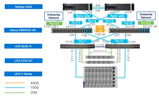
The multi-tenant network design deployed on a base FlexPod provides a secure, scalable, and flexible foundation for hosting multiple tenants with isolation. Figure 4 illustrates how the tenants (only three tenants shown) are layered on top of an existing FlexPod infrastructure.
In this deployment model:
● Cisco Nexus 93600CD-GX acts as the primary gateway, offering each tenant an entry point into their respective resources.
● A Secure Firepower Threat Defense virtual (FTDv) firewall is deployed for each tenant. Deploying separate instances of firewall provide granular control and management separation.
● FTDv appliances are managed using Secure Firewall Management Center (FMC). You can choose to manage the firewalls using device manager, but FMC standardizes and simplifies firewall policy management.
● Appropriately sized FTDv appliance is deployed (as a VM) in Cisco UCS and connected to port-group for outside (1232) and Inside VLANs (301+)
● All FTDv appliances use the same outside subnet and require a single gateway on Nexus 93600CD-GX.
● The protected traffic VLANs are defined on Cisco Nexus, Cisco UCS FI, and VMware distributed switch. This design ensures that each tenant's traffic remains separate and secure within its own VLAN.
To deploy this multi-tenant architecture on a FlexPod, following configurations are added to an existing FlexPod:
● VLANs, VRFs, and routing modifications on Cisco Nexus
● VLANs and vNICs modifications on Cisco UCS
● SVM and storage configuration on NetApp Controllers
● VLANs and port-group configurations on VMware vCenter
You should have deployed a base FlexPod as explained in the previous section. The configurations in this section build on or modify the base FlexPod design to deploy a multi-tenant architecture.
Procedure 1. Create the Tenant VLANs
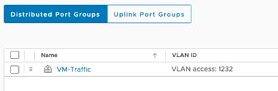
Step 1. Log into each Nexus switch and define the global (single) Firewall Outside VLAN (1232).
vlan <FW-Outside-Traffic-VLAN>
For example when FW outside VLAN is 1232:
vlan 1232
name VM-Traffic
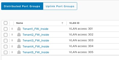
Step 2. On each Nexus switch, define the tenant Firewall inside (protected) VLANs for tenants.
vlan <Tenant<X>-Firwall-Inside-VLAN>
name Tenant<X>_FW_Inside
For example:
vlan 301
name Tenant1_FW_Inside
vlan 302
name Tenant2_FW_Inside
Step 3. On each Nexus switch, define the tenant NFS VLANs used for accessing NFS shares within tenant SVMs.
vlan <Tenant<X>-NFS-VLAN-ID>
name Tenant<X>-NFS
For example:
vlan 3301
name Tenant1-NFS
vlan 3302
name Tenant2-NFS
Step 4. On each Nexus switch, enable the VLANs on the VPC peer-link.
When the VPC peer-link is Port-Channel 10 and VLANs are defined for Tenant1-Tenant5:
interface port-channel10
description vPC Peer Link
switchport trunk allowed vlan add 301-305,1232,3301-3305
!
Step 5. On each Nexus switch, enable the global FW Outside, tenant FW Inside, and tenant NFS VLANs on Cisco UCS VPC interfaces.
When the Port-Channel 11-12 are connected to FIs and VLANs are defined for Tenant1-Tenant5:
interface port-channel11
description AB03-6536-A
switchport trunk allowed vlan add 301-305,1232, 3301-3305
!
interface port-channel12
description AB03-6536-B
switchport trunk allowed vlan add 301-305,1232, 3301-3305
!
Step 6. On each Nexus switch, enable Tenant SVM management and Tenant NFS VLANs on NetApp controller VPC interfaces.
Note: In this example, Tenant SVM management network is same as FW Inside network, but you can define a dedicated SVM management subnet/VLAN.
When the Port-Channel 13-14 are connected to NetApp controllers and VLANs are defined for Tenant1-Tenant5:
interface port-channel13
description AB03-A400-01
switchport trunk allowed vlan add 301-305,3301-3305
!
interface port-channel14
description AB03-A400-02
switchport trunk allowed vlan add 301-305,3301-3305
!
Procedure 2. Create the Firewall Outside SVI
Step 1. Log into the Nexus-1 and configure the SVI.
interface Vlan1232
description GW for FW Outside - 10.123.2.0/24 Network
no shutdown
no ip redirects
ip address 10.123.2.251/24
no ipv6 redirects
hsrp version 2
hsrp 1232
preempt delay minimum 300
priority 105
ip 10.123.2.254
!
Step 2. Log into the Nexus-2 and configure the SVI.
interface Vlan1232
description GW for FW-Outside - 10.123.2.0/24 Network
no shutdown
no ip redirects
ip address 10.123.2.252/24
no ipv6 redirects
hsrp version 2
hsrp 1232
ip 10.123.2.254
!
Procedure 1. Create the Tenant VLANs
Step 1. Log into Intersight and select Infrastructure Services.
Step 2. Click Policies in the left pane and find the VLAN policy.
Step 3. Click the name of the VLAN policy. Under the Actions button on top right, select Edit.
Step 4. Verify the Usage in Profiles tab and click Next.
Step 5. Click Add VLANs in the main window.
Step 6. Provide a name for the VLAN, VLAN ID and select Multicast Policy. Make sure Auto Allow in Uplinks is enabled.
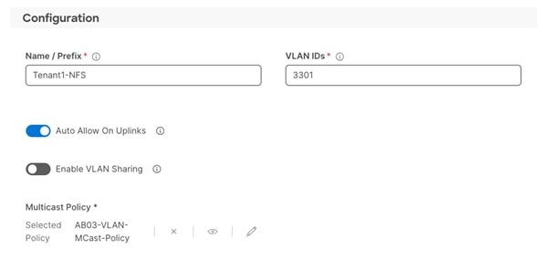
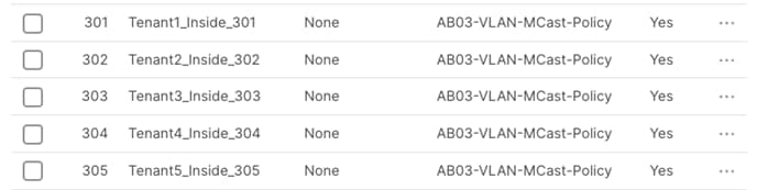
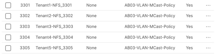
Step 7. After defining all the VLANs, make sure the VLAN policy contains all the VLANs:
![]()
Step 8. Click Save.
Procedure 2. Modify the VDS Ethernet Network Group policy to add VLANs
Step 1. Log into Intersight and select Infrastructure Services.
Step 2. Click on the Policies in the left pane and find the Ethernet Network Group policy for VDS.
Step 3. Click the name of the policy. Under the Actions button on top right, select Edit.
Step 4. Verify the Name, Tags (if defined) and Description and click Next.
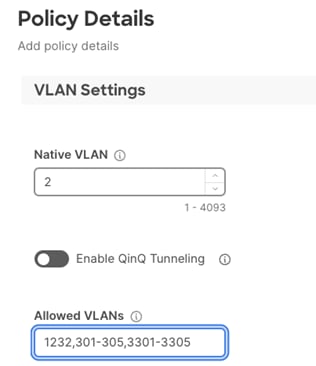
Step 5. Under the Allowed VLANs, add the FW outside, tenant FW Inside, and tenant NFS VLANs.
Note: The screenshot below only captures tenant VLANs. Other existing VLANs defined in VDS policy are not shown to avoid confusion.
Step 6. Click Save.
Step 7. In the left pane, click on Profiles and select UCS Server Profiles in the main window.
Step 8. Click “…” and select Deploy for all the severs attached to the Ethernet Network Group policy.
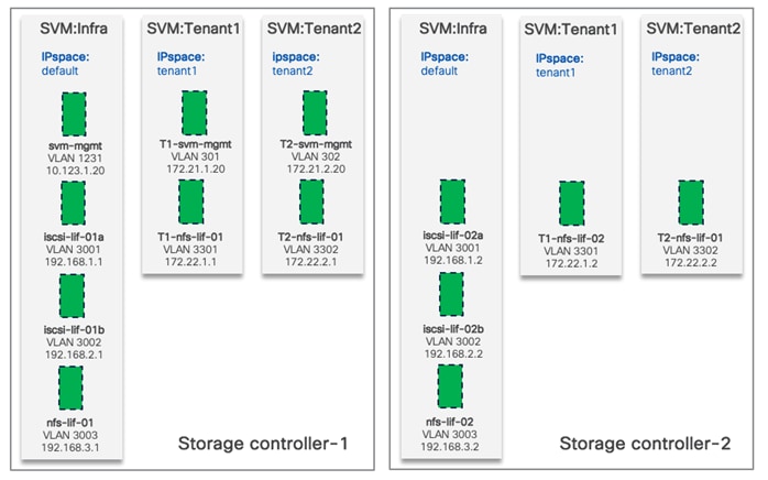
In Zero Trust framework for FlexPod, secure management and data isolation in storage are achieved by implementing separate storage virtual machine, IPspace, SVM management LIF, and NFS LIFs for each tenant in the NetApp AFF A400 storage system.
Figure 5 shows how the tenants, IPspaces and Logical Interfaces (LIFs) are defined on the two storage controllers. Management LIF is configured to move between the two controllers as needed. This design allows tenant VMs to access their NFS volumes directly therefore providing fast low-latency access.
Procedure 1. Configure IPspaces
Each tenant SVM is assigned to a separate IPspace to maintain IP separation. Log into NetApp AFF A400 controller to execute the following commands.
Step 1. To create an IPspace for a tenant SVM, use the following command syntax:
network ipspace create -ipspace <Tenant IPspace>
AB03-A400::> network ipspace create -ipspace Tenant<X> (where X = 1,2,3 etc.)
For example:
AB03-A400::> network ipspace create -ipspace Tenant1
AB03-A400::> network ipspace create -ipspace Tenant2
Procedure 2. Configure Storge Virtual Machine (SVM)
In this deployment, an infrastructure SVM is created to host the infrastructure services such as boot LUNs and NFS datastores to host the tenant VMs. Additional tenants are assigned dedicated SVMs to store their data and maintain isolation.
Step 1. To create a tenant SVM and assign it to the tenant IPspace, use the following command syntax.
vserver create -vserver <tenant-svm> -ipspace <tenant-IPspace>
AB03-A400::> vserver create -vserver Tenant1-SVM -ipspace Tenant<X> (where X = 1,2,3 etc.)
For example:
AB03-A400::> vserver create -vserver Tenant1-SVM -ipspace Tenant1
AB03-A400::> vserver create -vserver Tenant2-SVM -ipspace Tenant2
Step 2. Configure SVM protocol support. Check the allowed-protocols and disallowed-protocols configurations and update them based on your requirements with the following command syntaxes.
vserver show -vserver <tenant-svm> -fields allowed-protocols, disallowed-protocols
vserver add-protocols -vserver <tenant-svm> -protocols <protocols>
vserver remove-protocols -vserver <tenant-svm> -protocols <protocols>
To check currently configured protocols:
vserver show -vserver Tenant<X>-SVM -fields allowed-protocols,disallowed-protocols (where X = 1,2,3 etc.)
For example:
AB03-A400::> vserver show -vserver Tenant1-SVM,Tenant2-SVM -fields allowed-protocols,disallowed-protocols
vserver allowed-protocols disallowed-protocols
----------- -------------------------- --------------------
Tenant1-SVM nfs,cifs,fcp,iscsi,ndmp,s3 nvme
Tenant2-SVM nfs,cifs,fcp,iscsi,ndmp,s3 nvme
2 entries were displayed.
To remove unused protocols:
AB03-A400::> vserver remove-protocols -vserver Tenant<X>-SVM -protocols cifs,fcp,iscsi,ndmp,s3
For example:
AB03-A400::> vserver remove-protocols -vserver Tenant1-SVM -protocols cifs,fcp,iscsi,ndmp,s3
AB03-A400::> vserver remove-protocols -vserver Tenant2-SVM -protocols cifs,fcp,iscsi,ndmp,s3
To Verify the new protocol set:
AB03-A400::> vserver show -vserver Tenant1-SVM,Tenant2-SVM -fields allowed-protocols,disallowed-protocols
vserver allowed-protocols disallowed-protocols
----------- ----------------- ---------------------------
Tenant1-SVM nfs cifs,fcp,iscsi,ndmp,nvme,s3
Tenant2-SVM nfs cifs,fcp,iscsi,ndmp,nvme,s3
2 entries were displayed.
Procedure 3. Configure SVM aggregate list
Step 1. Add data aggregates to the SVM and show the configuration using the following command syntax.
vserver modify -vserver <tenant-svm> -aggr-list <aggregate-list>
vserver show -vserver <tenant-svm> -fields aggr-list
AB03-A400::> vserver modify -vserver Tenant<X>-SVM -aggr-list AB03_A400_01_NVME_SSD_1,AB03_A400_02_NVME_SSD_1 (where X = 1,2,3 etc.)
For example:
AB03-A400::> vserver modify -vserver Tenant1-SVM -aggr-list AB03_A400_01_NVME_SSD_1,AB03_A400_02_NVME_SSD_1
AB03-A400::> vserver modify -vserver Tenant2-SVM -aggr-list AB03_A400_01_NVME_SSD_1,AB03_A400_02_NVME_SSD_1
To verify the aggregates:
AB03-A400::> vserver show -vserver Tenant1-SVM,Tenant2-SVM -fields aggr-list
vserver aggr-list
----------- -----------------------------------------------
Tenant1-SVM AB03_A400_01_NVME_SSD_1,AB03_A400_02_NVME_SSD_1
Tenant2-SVM AB03_A400_01_NVME_SSD_1,AB03_A400_02_NVME_SSD_1
2 entries were displayed.
Procedure 4. Configure SVM NFS protocol support
Step 1. Create NFS server for the tenant SVM and enable or modify desired NFS version, transport support, VMware vStorage support and show the configurations with the following command syntax.
vserver nfs create -vserver <tenant-svm> -udp <enabled | disabled> -v3 <enabled | disabled> -v4.1 <enabled | disabled> -vstorage <enabled | disabled>
vserver nfs modify -vserver <tenant-svm> -udp <enabled | disabled> -v3 <enabled | disabled> -v4.1 <enabled | disabled> -vstorage <enabled | disabled>
vserver nfs show -vserver <tenant-svm> -fields udp,v3,v4.1,vstorage
AB03-A400::> vserver nfs create -vserver Tenant<X>-SVM -udp disabled -v3 enabled -v4.1 enabled -vstorage (where X = 1,2,3 etc.)
For example:
AB03-A400::> vserver nfs create -vserver Tenant1-SVM -udp disabled -v3 enabled -v4.1 enabled -vstorage enabled
AB03-A400::> vserver nfs create -vserver Tenant2-SVM -udp disabled -v3 enabled -v4.1 enabled -vstorage enabled
To verify:
AB03-A400::> vserver nfs show -vserver Tenant1-SVM,Tenant2-SVM -fields udp,v3,v4.1,vstorage
vserver v3 udp v4.1 vstorage
----------- ------- -------- ------- --------
Tenant1-SVM enabled disabled enabled enabled
Tenant2-SVM enabled disabled enabled enabled
2 entries were displayed.
Procedure 5. Configure SVM root volume load-sharing mirror
Step 1. Identify the node and aggregate of the Tenant SVM root volume, create a volume to be the load-sharing mirror of the Tenant SVM root volume only on the node that does not have the root volume using the following commands:
volume show -vserver <tenant-svm> -fields rootvolume,aggregate
volume create -vserver <tenant-svm> -volume <tenant-svm-rootvolume-lsm-name> -aggregate <root-volume-lsm-aggr-name> -size 1GB -type DP
AB03-A400::> vserver show -vserver Tenant<X>-SVM -fields rootvolume,aggregate (where X = 1,2,3 etc.)
For example:
AB03-A400::> vserver show -vserver Tenant1-SVM,Tenant2-SVM -fields rootvolume,aggregate
vserver rootvolume aggregate
----------- ---------------- -----------------------
Tenant1-SVM Tenant1_SVM_root AB03_A400_02_NVME_SSD_1
Tenant2-SVM Tenant2_SVM_root AB03_A400_02_NVME_SSD_1
2 entries were displayed.
AB03-A400::> volume create -vserver Tenant<X>-SVM -volume Tenant<X>_SVM_root_lsm01 -aggregate AB03_A400_01_NVME_SSD_1 -size 1GB -type DP (where X = 1,2,3 etc.)
For example:
AB03-A400::> volume create -vserver Tenant1-SVM -volume Tenant1_SVM_root_lsm01 -aggregate AB03_A400_01_NVME_SSD_1 -size 1GB -type DP
[Job 2408] Job succeeded: Successful
AB03-A400::> volume create -vserver Tenant2-SVM -volume Tenant2_SVM_root_lsm01 -aggregate AB03_A400_01_NVME_SSD_1 -size 1GB -type DP
[Job 2410] Job succeeded: Successful
Step 2. Create load-sharing mirror relationship for the tenant SVM root volume, initialize load-sharing mirror, and then verify the configuration using the following command syntax.
snapmirror create -source-path <tenant-svm:source-rootvolume-name> -destination-path <tenant-svm:mirror-rootvolume-name> -type LS -schedule 15min
snapmirror initialize-ls-set -source-path <tenant-svm:svm-rootvolume>
snapmirror show -vserver <tenant-svm>
AB03-A400::> snapmirror create -source-path Tenant<X>-SVM:Tenant<X>_SVM_root -destination-path Tenant<X>- SVM:Tenant<X>_SVM_root_lsm01 -type LS -schedule 15min (where X = 1,2,3 etc.)
For example:
AB03-A400::> snapmirror create -source-path Tenant1-SVM:Tenant1_SVM_root -destination-path Tenant1-SVM:Tenant1_SVM_root_lsm01 -type LS -schedule 15min
[Job 2418] Job is queued: snapmirror create for the relationship with destination "AB03-A400://Tenant1-SVM/Tenant1_SVM_r[Job 2418] Job succeeded: SnapMirror: done
AB03-A400::> snapmirror create -source-path Tenant2-SVM:Tenant2_SVM_root -destination-path Tenant2-SVM:Tenant2_SVM_root_lsm01 -type LS -schedule 15min
[Job 2420] Job is queued: snapmirror create for the relationship with destination "AB03-A400://Tenant2-SVM/Tenant2_SVM_r[Job 2420] Job succeeded: SnapMirror: done
AB03-A400::> snapmirror initialize-ls-set -source-path Tenant<X>-SVM:Tenant<X>_SVM_root (where X = 1,2,3 etc.)
For example:
AB03-A400::> snapmirror initialize-ls-set -source-path Tenant1-SVM:Tenant1_SVM_root
[Job 2422] Job is queued: snapmirror initialize-ls-set for source "AB03-A400://Tenant1-SVM/Tenant1_SVM_root".
AB03-A400::> snapmirror initialize-ls-set -source-path Tenant2-SVM:Tenant2_SVM_root
[Job 2423] Job is queued: snapmirror initialize-ls-set for source "AB03-A400://Tenant2-SVM/Tenant2_SVM_root".
AB03-A400::> snapmirror show -vserver Tenant<X>-SVM (where X = 1,2,3 etc.)
For example:
AB03-A400::> snapmirror show -vserver Tenant1-SVM,Tenant2-SVM
Progress
Source Destination Mirror Relationship Total Last
Path Type Path State Status Progress Healthy Updated
----------- ---- ------------ ------- -------------- --------- ------- --------
AB03-A400://Tenant1-SVM/Tenant1_SVM_root LS AB03-A400://Tenant1-SVM/Tenant1_SVM_root_lsm01 Snapmirrored Idle - true -
AB03-A400://Tenant2-SVM/Tenant2_SVM_root LS AB03-A400://Tenant2-SVM/Tenant2_SVM_root_lsm01 Snapmirrored Idle - true -
2 entries were displayed.
Procedure 6. Configure SVM login banner
Step 1. To create login banner for the Tenant SVM, use the following command syntax.
security login banner modify -vserver <tenant-svm> -message "This <tenant-svm> is reserved for authorized users only!"
AB03-A400::> security login banner modify -vserver Tenant<X>-SVM -message "Tenant<X>-SVM is reserved for authorized users only!" (where X = 1,2,3 etc.)
For example:
AB03-A400::> security login banner modify -vserver Tenant1-SVM -message "Tenant1-SVM is reserved for authorized users only!"
AB03-A400::> security login banner modify -vserver Tenant2-SVM -message "Tenant2-SVM is reserved for authorized users only!"
Procedure 7. Configure SVM audit log
Step 1. To create audit log volume and enable auditing configuration for the Tenant SVM, use the following command syntax.
volume create -vserver <tenant-svm> -volume <tenant_audit_log> -aggregate <aggregate-name> -size <volume-size> -state online -policy default -junction-path </tenant_audit_log> -space-guarantee none -percent-snapshot-space 0
vserver audit create -vserver <tenant-SVM> -destination /audit_log
vserver audit enable -vserver <tenant-SVM>
AB03-A400::> volume create -vserver Tenant<X>-SVM -volume Tenant<X>_audit_log -aggregate AB03_A400_02_NVME_SSD_1 -size 50GB -state online -policy default -junction-path /tenant<X>_audit_log -space-guarantee none -percent-snapshot-space 0 (where X = 1,2,3 etc.)
For example:
AB03-A400::> volume create -vserver Tenant1-SVM -volume Tenant1_audit_log -aggregate AB03_A400_02_NVME_SSD_1 -size 50GB -state online -policy default -junction-path /tenant1_audit_log -space-guarantee none -percent-snapshot-space 0
[Job 2433] Job succeeded: Successful
AB03-A400::> volume create -vserver Tenant2-SVM -volume Tenant2_audit_log -aggregate AB03_A400_02_NVME_SSD_1 -size 50GB -state online -policy default -junction-path /tenant2_audit_log -space-guarantee none -percent-snapshot-space 0
[Job 2435] Job succeeded: Successful
AB03-A400::> vserver audit create -vserver Tenant<X>-SVM -destination /tenant<X>_audit_log (where X = 1,2,3 etc.)
For example:
AB03-A400::> vserver audit create -vserver Tenant1-SVM -destination /tenant1_audit_log
AB03-A400::> vserver audit create -vserver Tenant2-SVM -destination /tenant2_audit_log
AB03-A400::> vserver audit enable -vserver Tenant<X>-SVM (where X = 1,2,3 etc.)
For example:
AB03-A400::> vserver audit enable -vserver Tenant1-SVM
AB03-A400::> vserver audit enable -vserver Tenant2-SVM
Procedure 8. Configure network broadcast domain
Step 1. To create SVM management and NFS data broadcast domains for tenants, with a maximum transmission unit (MTU) of 1500 and 9000, respectively, use the following command syntax:
network port broadcast-domain create -broadcast-domain <tenant-svm-mgmt-broadcast-domain> -mtu 1500 -ipspace <tenant-IPspace>
network port broadcast-domain create -broadcast-domain <tenant-nfs-broadcast-domain> -mtu 9000 -ipspace <tenant-IPspace>
AB03-A400::> network port broadcast-domain create -broadcast-domain Tenant<X>-SVM-MGMT -mtu 1500 -ipspace Tenant<X> (where X = 1,2,3 etc.)
For example:
AB03-A400::> network port broadcast-domain create -broadcast-domain Tenant1-SVM-MGMT -mtu 1500 -ipspace Tenant1
AB03-A400::> network port broadcast-domain create -broadcast-domain Tenant2-SVM-MGMT -mtu 1500 -ipspace Tenant2
AB03-A400::> network port broadcast-domain create -broadcast-domain TenantX>-NFS -mtu 9000 -ipspace Tenant<X> (where X = 1,2,3 etc.)
For example:
AB03-A400::> network port broadcast-domain create -broadcast-domain Tenant1-NFS -mtu 9000 -ipspace Tenant1
AB03-A400::> network port broadcast-domain create -broadcast-domain Tenant2-NFS -mtu 9000 -ipspace Tenant2
Procedure 9. Configure management and NFS VLANs
Step 1. To create management VLAN ports and NFS VLAN ports for tenants and add them to their respective network broadcast domains, use the following command syntaxes:
network port vlan create –node <st-node01> -vlan-name a0a-<tenant-svm-mgmt-vlan-id>
network port vlan create –node <st-node02> -vlan-name a0a-<tenant-svm-mgmt-vlan-id>
network port vlan create –node <st-node01> -vlan-name a0a-<tenant-nfs-vlan-id>
network port vlan create –node <st-node02> -vlan-name a0a-<tenant-nfs-vlan-id>
network port broadcast-domain add-ports -broadcast-domain <tenant-svm-mgmt-broadcast-domain> -ports <st-node01>:a0a-<tenant-svm-mgmt-vlan-id>,<st-node02>:a0a-<tenant-svm-mgmt-vlan-id>
network port broadcast-domain add-ports -broadcast-domain <tenant-nfs-broadcast-domain> -ports <st-node01>:a0a-<tenant-nfs-vlan-id>,<st-node02>:a0a-<tenant-nfs-vlan-id>
AB03-A400::> network port vlan create -node AB03-A400-01 -vlan-name a0a-<tenant-svm-mgmt-vlan-id>
AB03-A400::> network port vlan create -node AB03-A400-02 -vlan-name a0a-<tenant-svm-mgmt-vlan-id>
For example, when tenant-svm-mgmt-vlan-id for Tenant1 is 301 and for Tenant2 is 302:
AB03-A400::> network port vlan create -node AB03-A400-01 -vlan-name a0a-301
AB03-A400::> network port vlan create -node AB03-A400-02 -vlan-name a0a-301
AB03-A400::> network port vlan create -node AB03-A400-01 -vlan-name a0a-302
AB03-A400::> network port vlan create -node AB03-A400-02 -vlan-name a0a-302
AB03-A400::> network port vlan create -node AB03-A400-01 -vlan-name a0a-<tenant-nfs-vlan-id>
AB03-A400::> network port vlan create -node AB03-A400-02 -vlan-name a0a-<tenant-nfs-vlan-id>
For example, when tenant-nfs-vlan-id for Tenant1 is 3301 and for Tenant2 is 3302:
AB03-A400::> network port vlan create -node AB03-A400-01 -vlan-name a0a-3301
AB03-A400::> network port vlan create -node AB03-A400-02 -vlan-name a0a-3301
AB03-A400::> network port vlan create -node AB03-A400-01 -vlan-name a0a-3302
AB03-A400::> network port vlan create -node AB03-A400-02 -vlan-name a0a-3302
AB03-A400::> network port broadcast-domain add-port -broadcast-domain Tenant<X>-SVM-MGMT -port AB03-A400-01:a0a-<tenant-svm-mgmt-vlan-id>, AB03-A400-02:a0a-<tenant-svm-mgmt-vlan-id> -ipspace Tenant<X>
For example when tenant-svm-mgmt-vlan-id for Tenant1 is 301 and for Tenant2 is 302:
AB03-A400::> network port broadcast-domain add-port -broadcast-domain Tenant1-SVM-MGMT -port AB03-A400-01:a0a-301, AB03-A400-02:a0a-301 -ipspace Tenant1
AB03-A400::> network port broadcast-domain add-port -broadcast-domain Tenant2-SVM-MGMT -port AB03-A400-01:a0a-302, AB03-A400-02:a0a-302 -ipspace Tenant2
AB03-A400::> network port broadcast-domain add-port -broadcast-domain Tenant<X>-NFS -port AB03-A400-01:a0a-<tenant-nfs-vlan-id>, AB03-A400-02:a0a-<tenant-nfs-vlan-id> -ipspace Tenant<X>
For example when tenant-nfs-vlan-id for Tenant1 is 3301 and for Tenant2 is 3302:
AB03-A400::> network port broadcast-domain add-port -broadcast-domain Tenant1-NFS -port AB03-A400-01:a0a-3301, AB03-A400-02:a0a-3301 -ipspace Tenant1
AB03-A400::> network port broadcast-domain add-port -broadcast-domain Tenant2-NFS -port AB03-A400-01:a0a-3302, AB03-A400-02:a0a-3302 -ipspace Tenant2
Procedure 10. Configure SVM LIFs and access
To create tenant SVM administrator and SVM administration LIF in the tenant SVM management network, follow these steps:
Step 1. To create tenant SVM management LIF, use the following syntax:
network interface create –vserver <tenant-svm> –lif <tenant-svm-mgmt> -service-policy default-management –home-node <st-node02> -home-port a0a-<tenant-svm-mgmt-vlan-id> –address <tenant-svm-mgmt-ip> -netmask <tenant-svm-mgmt-mask> -status-admin up –failover-policy broadcast-domain-wide –auto-revert true
AB03-A400::> network interface create -vserver Tenant<X>-SVM -lif tenant<X>-svm-mgmt-service-policy default-management -home-node AB03-A400-02 -home-port a0a-<tenant-svm-mgmt-vlan-id> -address <tenant-svm-mgmt-ip> -netmask <tenant-svm-mgmt-mask> -status-admin up -failover-policy broadcast-domain-wide -auto-revert true (where X = 1,2,3 etc.)
For example:
AB03-A400::> network interface create -vserver Tenant1-SVM -lif tenant1-svm-mgmt –service-policy default-management -home-node AB03-A400-02 -home-port a0a-301 -address 172.21.1.20 -netmask 255.255.255.0 -status-admin up -failover-policy broadcast-domain-wide -auto-revert true
AB03-A400::> network interface create -vserver Tenant2-SVM -lif tenant2-svm-mgmt –service-policy default-management -home-node AB03-A400-02 -home-port a0a-302 -address 172.21.2.20 -netmask 255.255.255.0 -status-admin up -failover-policy broadcast-domain-wide -auto-revert true
Step 2. To create a default route that enables the SVM management interface to reach the outside world, use the following syntax:
network route create –vserver <tenant-svm> -destination 0.0.0.0/0 –gateway <tenant-svm-mgmt-gateway>
AB03-A400::> network route create -vserver Tenant<X>-SVM -destination 0.0.0.0/0 -gateway <tenant-svm-mgmt-gateway>
For example:
AB03-A400::> network route create -vserver Tenant1-SVM -destination 0.0.0.0/0 -gateway 172.21.1.254
AB03-A400::> network route create -vserver Tenant2-SVM -destination 0.0.0.0/0 -gateway 172.21.2.254
Step 3. To set a password for the SVM admin user (vsadmin) and unlock the user, use the following syntax.
:security login password –username vsadmin –vserver <tenant-svm>
security login unlock –username vsadmin –vserver <tenant-svm>
AB03-A400::> security login password -username vsadmin -vserver Tenant<X>-SVM
For example:
AB03-A400::> security login password -username vsadmin -vserver Tenant1-SVM
Enter a new password:
Enter it again:
AB03-A400::> security login password -username vsadmin -vserver Tenant2-SVM
Enter a new password:
Enter it again:
AB03-A400::> security login unlock -username vsadmin -vserver Tenant<X>-SVM
For example:
AB03-A400::> security login unlock -username vsadmin -vserver Tenant1-SVM
AB03-A400::> security login unlock -username vsadmin -vserver Tenant2-SVM
Procedure 11. Create NFS LIF
Step 1. To create tenant NFS LIFs in the tenant SVM, use the following syntax:
network interface create -vserver <tenant-SVM> -lif <tenant-nfs-lif-01> –service-policy default-data-files -home-node <st-node01> -home-port a0a-<tenant-nfs-vlan-id> –address <tenant-node01-nfs-lif-01-ip> -netmask <tenant-node01-nfs-lif-01-mask> -status-admin up –failover-policy broadcast-domain-wide –auto-revert true
network interface create -vserver <tenant-SVM> -lif <tenant-nfs-lif-02> –service-policy default-data-files -home-node <st-node02> -home-port a0a-<tenant-nfs-vlan-id> –address <tenant-node02-nfs-lif-01-ip> -netmask <tenant-node01-nfs-lif-01-mask> -status-admin up –failover-policy broadcast-domain-wide –auto-revert true
AB03-A400::> network interface create -vserver Tenant<X>-SVM -lif tenant<X>-nfs-lif-01 –service-policy default-data-files -home-node AB03-A400-01 -home-port a0a-<tenant-nfs-vlan-id> -address <tenant-node01-nfs-lif-01-ip> -netmask <tenant-node01-nfs-lif-01-mask> -status-admin up -failover-policy broadcast-domain-wide -auto-revert true
For example:
AB03-A400::> network interface create -vserver Tenant1-SVM -lif tenant1-nfs-lif-01 –service-policy default-data-files -home-node AB03-A400-01 -home-port a0a-3301 -address 172.22.1.1 -netmask 255.255.255.0 -status-admin up -failover-policy broadcast-domain-wide -auto-revert true
AB03-A400::> network interface create -vserver Tenant2-SVM -lif tenant2-nfs-lif-01 -service-policy default-data-files -home-node AB03-A400-01 -home-port a0a-3302 -address 172.22.2.1 -netmask 255.255.255.0 -status-admin up -failover-policy broadcast-domain-wide -auto-revert true
AB03-A400::> network interface create -vserver Tenant<X>-SVM -lif tenant<X>-nfs-lif-02 –service-policy default-data-files -home-node AB03-A400-02 -home-port a0a-<tenant-nfs-vlan-id> -address <tenant-node02-nfs-lif-02-ip> -netmask <tenant-node01-nfs-lif-02-mask> -status-admin up -failover-policy broadcast-domain-wide -auto-revert true
For example:
AB03-A400::> network interface create -vserver Tenant1-SVM -lif tenant1-nfs-lif-02 –service-policy default-data-files -home-node AB03-A400-02 -home-port a0a-3301 -address 172.22.1.2 -netmask 255.255.255.0 -status-admin up -failover-policy broadcast-domain-wide -auto-revert true
AB03-A400::> network interface create -vserver Tenant2-SVM -lif tenant2-nfs-lif-02 –service-policy default-data-files -home-node AB03-A400-02 -home-port a0a-3302 -address 172.22.2.2 -netmask 255.255.255.0 -status-admin up -failover-policy broadcast-domain-wide -auto-revert true
Procedure 12. Create NFS volumes
Step 1. To create NFS volumes for tenants in the tenant SVMs, use the following syntax:
volume create -vserver <tenant-SVM> -volume <tenant-nfs-volume> -aggregate <aggr1_node01 or aggr1_node02> -size <size> -state online -policy default -junction-path </tenant-junction-path> -space-guarantee none -percent-snapshot-space 0
AB03-A400::> volume create -vserver Tenant<X>-SVM -volume tenant<X>_nfs_1 -aggregate AB03_A400_<Y>_NVME_SSD_1 -size 500GB -state online -policy default -junction-path /tenant<X>_nfs_1 -space-guarantee none -percent-snapshot-space 0 (where X = 1,2,3 etc. and Y = 01 or 02)
For example:
AB03-A400::> volume create -vserver Tenant1-SVM -volume tenant1_nfs_1 -aggregate AB03_A400_01_NVME_SSD_1 -size 500GB -state online -policy default -junction-path /tenant1_nfs_1 -space-guarantee none -percent-snapshot-space 0
AB03-A400::> volume create -vserver Tenant2-SVM -volume tenant2_nfs_1 -aggregate AB03_A400_02_NVME_SSD_1 -size 500GB -state online -policy default -junction-path /tenant2_nfs_1 -space-guarantee none -percent-snapshot-space 0
Procedure 13. Configure NFS export policies
Step 1. To export the NFS volumes created in the last step to tenant NFS clients, proper export policies need to be created and assigned. To create an NFS export policy and apply it to the tenant SVM, use the following syntax:
vserver export-policy rule create –vserver <tenant-svm> -policyname default –ruleindex 1 –protocol nfs -clientmatch <tenant_client_nfs_ip_subnet> -rorule sys –rwrule sys -superuser sys –allow-suid true
volume modify -vserver <tenant-svm> -volume <tenant-nfs-volume>_root -policy default
AB03-A400::> vserver export-policy rule create -vserver Tenant<X>-SVM -policyname default -ruleindex 1 -protocol nfs -clientmatch <tenant_client_nfs_ip_subnet> -rorule sys -rwrule sys -superuser sys -allow-suid true
For example:
AB03-A400::> vserver export-policy rule create -vserver Tenant1-SVM -policyname default -ruleindex 1 -protocol nfs -clientmatch 172.22.1.0/24 -rorule sys -rwrule sys -superuser sys -allow-suid true
AB03-A400::> vserver export-policy rule create -vserver Tenant2-SVM -policyname default -ruleindex 1 -protocol nfs -clientmatch 172.22.2.0/24 -rorule sys -rwrule sys -superuser sys -allow-suid true
AB03-A400::> volume modify -vserver Tenant<X>-SVM -volume Tenant<X>_SVM_root -policy default
For example:
AB03-A400::> volume modify -vserver Tenant1-SVM -volume Tenant1_SVM_root -policy default
AB03-A400::> volume modify -vserver Tenant2-SVM -volume Tenant2_SVM_root -policy default
In this procedure, several port groups are configured on VMware vSphere. In the VDS configuration, port-groups for firewalls and NFS will be defined. The steps below detail two models that can be configured for tenant data and/or VM isolation:
● Tenants VMs are installed on the Infrastructure NFS data volume. Tenant application data is provisioned using NFS volumes in a tenant specific SVM. An isolated VLAN provides tenant VMs direct network access to their tenant specific NFS shares.
● For additional isolation, you can choose to create separate volumes within each tenant SVM and mount them in VMware vSphere as dedicated tenant datastores for deploying tenant VMs.
For storage access, IPspaces, dedicated VLANs, non-routed subnets, and stringent export policies limit data access.
Procedure 1. Optional - Configure VM networking to mount tenant specific NFS shares
To allow tenant VMs access NFS shares in tenant SVMs, follow these steps:
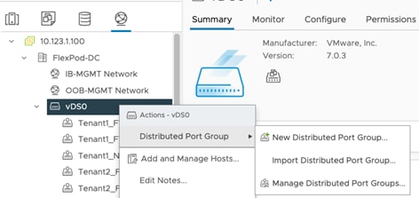
Step 1. Log into VMware vCenter, click Network and select the VDS.
Step 2. Right-click the VDS name, select Distributed Port Group and then New Distributed Port Group.
Step 3. Provide the name and VLAN ID to add port-groups for FW outside VLAN, tenant FW inside VLANs and tenant NFS VLANs.

Step 4. To allow tenant VMs to access NFS shares in tenant SVMs, a second vNIC is created and assigned to appropriate port group. Right-click the VM and select Edit Settings.
Step 5. On the top right hand, click ADD NEW DEVICE and select Network Adapter.
Step 6. From the drop-down list, next to New Network, select Browse… and then appropriate port-group. Click OK.
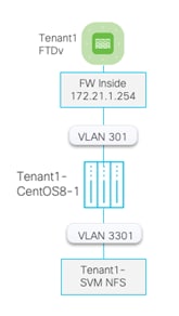
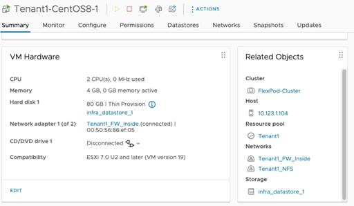
The following image shows a Tenant1 VM, hosted on shared Infra_datastore_1 and connected to two networks: Tenant1-FW-Inside and Tenant1-NFS:
Step 7. Configure the IP address on the newly added VM NIC.
Step 8. Set the MTU on the newly added NIC to jumbo frame.
ens224: flags=4163<UP,BROADCAST,RUNNING,MULTICAST> mtu 9000
inet 172.22.1.102 netmask 255.255.255.0 broadcast 172.22.1.255
inet6 fe80::1807:1e88:99a9:30ea prefixlen 64 scopeid 0x20<link>
ether 00:50:56:86:30:d2 txqueuelen 1000 (Ethernet)
RX packets 356669 bytes 58623025 (55.9 MiB)
RX errors 0 dropped 345112 overruns 0 frame 0
TX packets 5146 bytes 41453869 (39.5 MiB)
TX errors 0 dropped 0 overruns 0 carrier 0 collisions 0
Step 9. Mount the tenant specific NFS volume.
The example below shows fstab entry on a CentOS 8 VM to mount NFS share /tenant1_nfs_1 from Tenant1-SVM LIF 172.22.1.1 as /mnt/mysql-data:
[root@Tenant1-CentOS8-1 ~]# more /etc/fstab | grep nfs
172.22.1.1:/tenant1_nfs_1 /mnt/mysql-data nfs auto,noatime,nolock,bg,nfsvers=3,intr,tcp,actimeo=1800 0 0
[root@Tenant1-WP-DB ~]# mount /mnt/mysql-data/
[root@Tenant1-WP-DB ~]# ls /mnt/mysql-data/
mysql vdbench
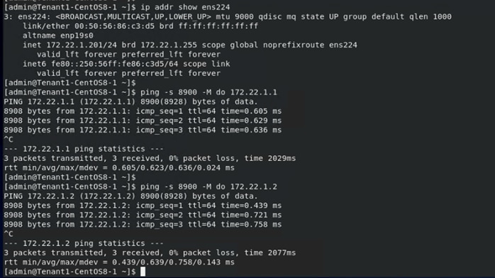
Step 10. To verify connectivity and correct Jumbo MTU setup, the screenshot below shows an example for a VM in Tenant1 where the NFS NIC is configured with jumbo frame and the connectivity with the NFS servers is tested using a jumbo packet size.
Procedure 2. Optional - Mount NFS share to ESXi hosts and install tenant VMs on the tenant datastore
For the tenant NFS shares to be mounted on all the ESXi hosts in the cluster, create VMkernel ports for tenant NFS traffic on all ESXi hosts with proper tenant NFS network and jumbo frame MTU configurations. After the tenant NFS share is mounted on all hosts as a datastore, tenant can deploy their VMs on their assigned datastore.
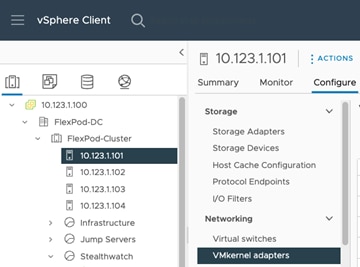
Step 1. Log into VMware vCenter and click an ESXi host.
Step 2. Select Configure in the main window and then select VMkernel adapters.
Step 3. Click ADD NETWORKING and select VMkernel Network Adapter. Click NEXT.
Step 4. Click Select an existing network and click BROWSE… Pick appropriate port-group (for example, Tenant1-NFS) and click NEXT.
Step 5. Provide a Network Label, make sure the MTU is set to 9000 and click NEXT.
Step 6. Select Use Static IPv4 settings and provide an IP address and subnet mask. There is no need to define a default gateway because both the VMkernel port on ESXi host and LIF on NetApp controllers are in the same subnet. Click NEXT.
Step 7. Verify the settings and click FINISH.
Step 8. Repeat steps 1 - 7 to define VMkernel adapters for all the tenants.
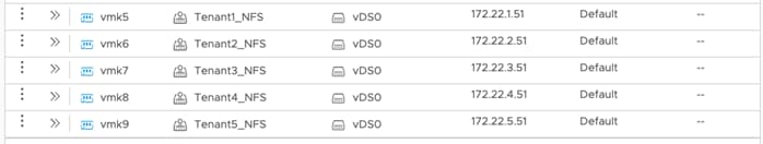
Step 9. To verify the connectivity to NFS servers from an ESXi host, SSH to the ESXi host and use the vmkping command to verify connectivity and Jumbo MTU settings.
In the example, the IP address 172.22.4.1 is one of the NFS LIFs for Tenant 4 and vmk8 is the vmkernel port for the Tenant4_NFS network.
[root@AB03-ESXi-01:~] vmkping -s 8900 -I vmk8 172.22.4.2
PING 172.22.4.2 (172.22.4.2): 8900 data bytes
8908 bytes from 172.22.4.2: icmp_seq=0 ttl=64 time=0.229 ms
8908 bytes from 172.22.4.2: icmp_seq=1 ttl=64 time=0.488 ms
8908 bytes from 172.22.4.2: icmp_seq=2 ttl=64 time=0.526 ms
--- 172.22.4.2 ping statistics ---
3 packets transmitted, 3 packets received, 0% packet loss
round-trip min/avg/max = 0.229/0.414/0.526 ms
[root@AB03-ESXi-01:~]
Step 10. Click the Datastore tab, right-click the Data Center name, and select Storage > New Datastore.
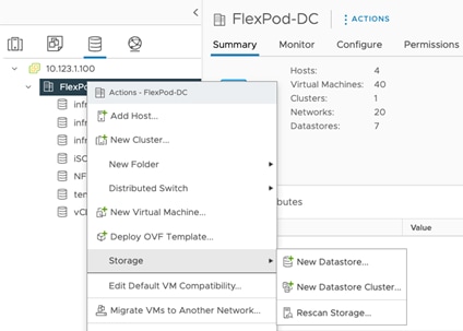
Step 11. Select NFS and click NEXT.
Step 12. Select the NFS version and click NEXT.
Step 13. Provide a name for the datastore, mountpoint folder and the SVM LIF IP address. Click NEXT.
Step 14. Select all the hosts where the datastore needs to be mounted. Click NEXT.
Step 15. Verify details and click FINISH.
The following screenshots show the information of a NFS datastore from the Tenant4-SVM that is mounted on all the hosts in the VMware cluster:
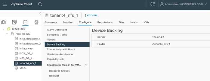
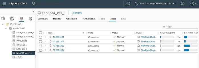
Any tenant VMs deployed on this datastore will be hosted on a tenant dedicated SVM. This datastore allows both the VM and its data to be isolated for all tenants.
Deploy Secure Firewall Threat Defense
This chapter contains the following:
● Deploy Firewall Threat Defense Virtual
● Firewall Management Center Deployment
Cisco provides its firewall and threat defense solutions in several different form factors to meet various deployment needs. FlexPod customers can choose to deploy either physical or virtual appliances depending on their throughput and feature needs.
● Cisco Secure Firewall Threat Defense: Hardware appliances dedicated to firewall, VPN, IPS/IDS, and advanced threat protection.
● Cisco Secure Firewall Threat Defense Virtual (FTDv) is the virtualized options for Cisco’s proven network firewall with Snort IPS, URL filtering, and malware defense.
In this deployment, the Cisco Secure Firewall Threat Defense virtual (FTDv) appliance is utilized to secure the tenant network perimeter including access to the resources hosted within the tenant segments. This design enables security controls like filtering, intrusion prevention and malware detection at the edge of the tenant infrastructure.
A separate instance of FTDv is deployed for every tenant. All the FTDv appliances are managed using Cisco Secure Firewall Management Center Virtual (FMC). The Secure Firewall Management Center Virtual Appliance provides:
● Common base access control policy that blocks all the traffic from outside (unprotected) to inside (protected) interfaces.
● Common NAT policy that allows all the inside hosts to use outside interface’s IP address to communicate to the outside world.
● Tenant specific access control policies allowing application traffic from outside to inside interfaces.
● Tenant specific static NAT mappings for application web (and similar) services.
● DHCP can be enabled on FTDv inside interface for VMs addressing (if desired).
● Common or tenant specific IPS and malware protection policies.
Deploy Firewall Threat Defense Virtual
Cisco offers threat defense virtual devices designed for VMware vSphere environment. These virtual threat defense devices are distributed as Open Virtualization Format (OVF) packages, which can be downloaded from Cisco.com.
Procedure 1. Download the Software
Step 1. To download the FTDv software, follow this link and download the OVF file for VMware: Cisco_Secure_Firewall_Threat_Defense_Virtual-7.2.5-208.tar.gz.
Step 2. Untar and unzip the file. When using VMware vCenter, you will need the .vmdk, .ovf, and .mf files containing “Virtual-VI” in the name.
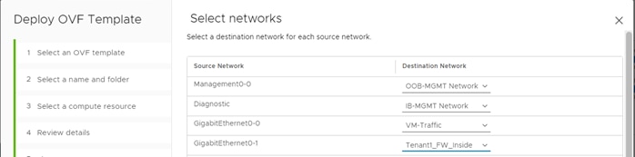
Procedure 2. Identify FTDv Interface Mapping
Table 4 lists the FTDv interface mappings that will be used for all tenants:
Table 4. FTDv Interface Mapping
| Network Adapter |
Source Networks |
Destination Networks |
Function |
| Network adapter 1 |
Management0-0 |
OOB-Mgmt-Network Port Group (VLAN 1230) |
Management |
| Network adapter 2 |
Diagnostic0-0 |
IB-Mgmt-Network Port Group (VLAN 1231) |
Diagnostic |
| Network adapter 3 |
GigabitEthernet0-0 |
VM-Traffic (FW Outside) Port-group (VLAN 1232) |
FW Outside |
| Network adapter 4 |
GigabitEthernet0-1 |
TenantX-FW-Inside Port Group (VLAN 301+) |
FW Inside |
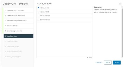
Procedure 3. Identify performance tier
Use Table 5 to identify the correct VM sizing for the FTDv deployment. The information about number of CPUs and amount of memory will be used during OVF deployment.
Table 5. FTDv CPU/Memory Configuration
| Performance Tier |
Device Specifications (Core/RAM) |
Rate Limit |
RA VPN Session Limit |
| FTDv5, 100Mbps |
4 core/8 GB |
100Mbps |
50 |
| FTDv10, 1Gbps |
4 core/8 GB |
1Gbps |
250 |
| FTDv20, 3Gbps |
4 core/8 GB |
3Gbps |
250 |
| FTDv30, 5Gbps |
8 core/16 GB |
5Gbps |
250 |
| FTDv50, 10Gbps |
12 core/24 GB |
10Gbps |
750 |
| FTDv100, 16Gbps |
16 core/32 GB |
16Gbps |
10,000 |
Procedure 4. OVF Deployment in the VMware environment
Please follow this guide to deploy the OVF using VMware vCenter.
Step 1. When going through the deployment wizard, you will be prompted to select a CPU/Memory configuration. Use the Performance Tiers listed in Table 5 to select the correct values.
Step 2. Select the interface mapping for at least 4 interfaces. Make sure you use VMXNET3 interface types (default). You can have 10 interfaces when you deploy the threat defense virtual. For data interfaces, make sure that the Source Networks map to the correct Destination Networks, and that each data interface maps to a unique subnet or VLAN.
Note: You do not need to use all threat defense virtual interfaces; for interfaces you do not intend to use, you can simply leave the interface disabled within the threat defense virtual configuration. Make sure you read and follow the interface guidelines and limitations.
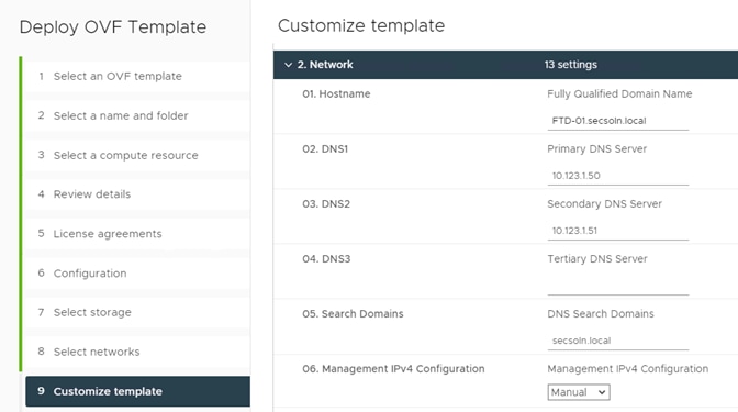
Step 3. Provide the password, FW name, and DNS information:
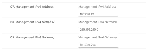
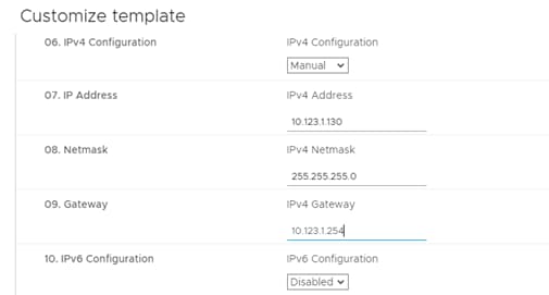
Step 4. Provide a IPv4 management IP address, netmask, and gateway:
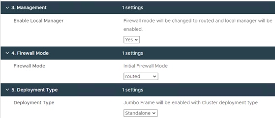
Step 5. Select YES for Local Manager for now but this FTDv will be added to FMC later.
Step 6. Select Initial Firewall Mode as routed.
Step 7. Select the Deployment type as Standalone. You can select the deployment type as cluster however in this validation, standalone mode was utilized.
Step 8. Do not add the registration information (IP address, and so on) for FMC now.
Step 9. When FTDv is successfully deployed, use vCenter to power on the VM.
Step 10. You can now access the FTDv using the management IP addresses defined at the time of OVF deployment, https://<FTDv_IP_Address> and using “admin” and password set at the time of OVF deployment to log into the FTDv.
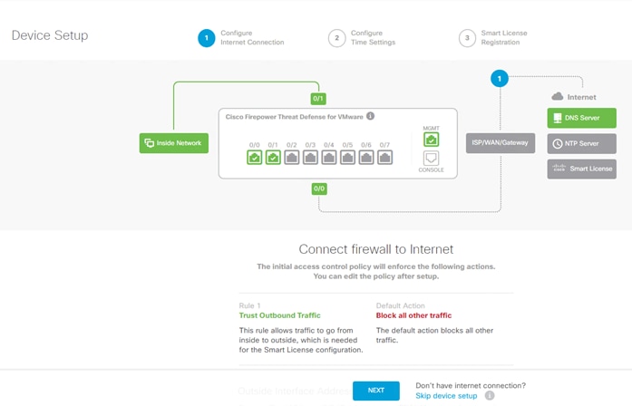
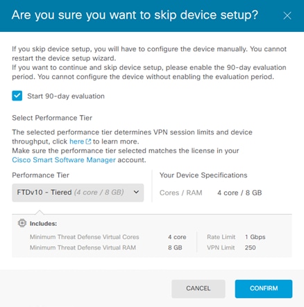
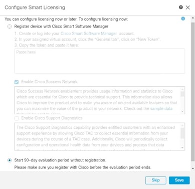
Step 11. Click Skip device setup and select a Performance Tier and select Start 90-day evaluation.
Step 12. Click CONFIRM.
Note: FTDv will be added to Firewall Management Center (FMC) later and the device configuration will be pushed from the FMC.
Step 13. Repeat these steps to add all the FTDv virtual appliances, one for each tenant.
Firewall Management Center Deployment
The Secure Firewall Management Center (FMC) Virtual Appliance brings full firewall functionality to virtualized environments to secure data center traffic and multi-tenant environments. A single instance of FMC is deployed as a central management device to manage all the tenant firewalls.
Procedure 1. Identify the Virtual Appliance performance tier
Follow the performance guidelines as explained in this document. Depending on the number of tenants, the CPU and memory settings of the appliance can be adjusted. By default, the FMC VM is allocated 32GB of memory and 8 CPUs (refer to Table 2 in the document).
Procedure 2. Download FMC software
Step 1. Follow this link to download the FMC software.
Step 2. Download the VMware installation package: Cisco_Secure_FW_Mgmt_Center_Virtual_VMware-7.2.5-208.tar.gz.
Step 3. Untar and unzip the file. When using VMware vCenter, you will need the .vmdk, .ovf, and .mf files containing “Virtual-VI” in the file name.
Procedure 3. OVF deployment in the VMware environment
Please follow this guide to deploy the OVF. Provided below is helpful guidance when deploying FMC virtual appliance. Provided below is helpful guidance for deploying FMC in the environment.
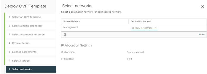
Step 1. For management network, pick the IB-Mgmt-Network (VLAN 1231).
Step 2. Provide the password, FMC name, NTP, and DNS information.
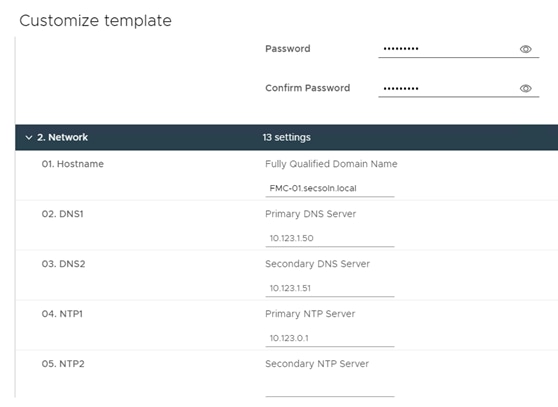
Step 3. Provide IP address, netmask, and gateway information.
Step 4. When FMC is successfully deployed, power on the VM.
Step 5. Access FMC Web console by accessing https://<FMC_IP_Address> and using “admin” and password set at the time of OVF deployment.
Note: If the gateway is not properly set, you will need to access FMC web console from a VM in the same subnet as FMC. Once logged in, the gateway can be set by going into Settings (gear icon) > Configuration > Management Interfaces.
Step 6. Register FMC with Cisco Smart Software manager as shown in the initial splash screen and enable Cisco Success Network. Alternately, you can select Start 90-day evaluation period without registration and enter the licensing information later.
Step 7. Click Save.
Note: For details on FMC licensing including licensing for air-gapped deployment, refer to the administration guide.
Follow this procedure to add FTDv devices to FMC.
Procedure 1. Prepare FTDv
Step 1. Log into the FTDv management console.
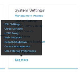
Step 2. On the main page, under System Settings, click See More and select Central Management.
Step 3. Click PROCEED and then click Continue.
Step 4. Provide the IP address of FMC and create a Registration Key. This Registration key (password) will be used in FMC to add FTDv in the next procedure.
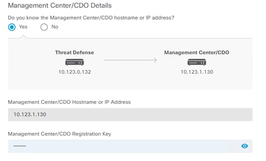
Step 5. Verify the hostname and management interface and click CONNECT.
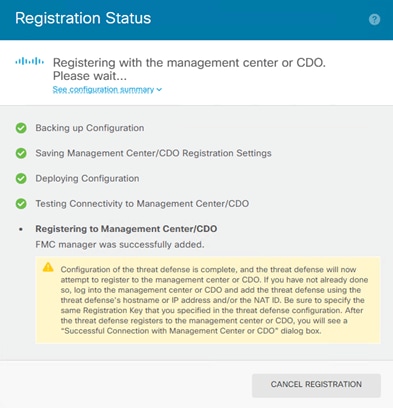
Step 6. The Registration Status box will appear, wait for registration to go through.
Procedure 2. Add device in FMC
Step 1. Log int the management console of FMC.
Step 2. Select Devices > Device Management.
Step 3. From the Add drop-down list, select Add Device.
Step 4. Provide the Host IP address of FTDv you want to add, a Display Name for the device, and Registration Key created when generating registration request in the last procedure.
Step 5. Under Access Control Policy, select Create New Policy.
Step 6. Provide a name for the New Policy and set the default action to Block all traffic.
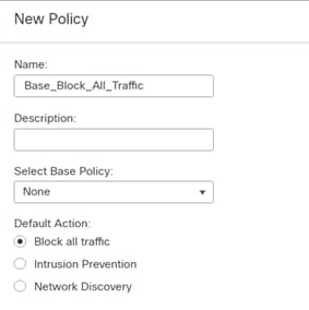
Step 7. Click Save.
Step 8. Select a Performance Tier.
Note: For details on available performance tiers, refer to the FTDv deployment procedures.
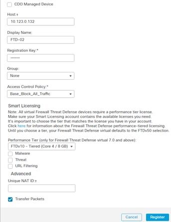
Step 9. Click Register.
The FTDv will be added to FMC.
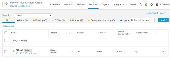
Step 10. To verify, revisit the FTDv management console window. Registration Status will show success.
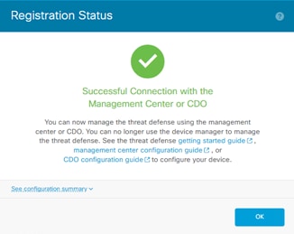
Note: You will lose access to the device manager at this time and FTDv will be managed by FMC.
Step 11. Repeat these steps to add all the FTDv virtual appliances to FMC.
In this section, the FTDv appliances interfaces and routing will be configured.
Note: You can optionally set the FTDv appliance as a DHCP server for tenant VMs by going to Device > Select the FTDv > DHCP.
Procedure 1. Configure Interfaces
Step 1. Log into FMC console and select Devices > Device Management.
Step 2. Click the name of the FTDv appliance you want to configure.
Step 3. In the main screen, select Interfaces.
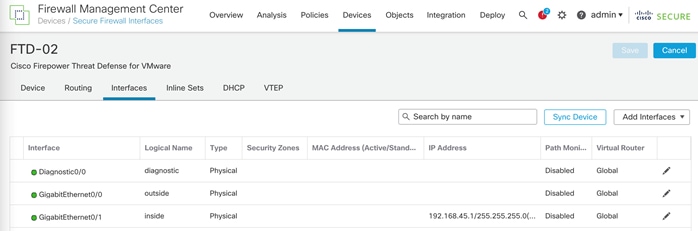
Step 4. Click the pencil to edit the Diagnostic0/0 interface. Under IPv4, enter an IP address for the interface. In this deployment, the Diagnostic0/0 interface is mapped to and assigned an IP address in the IB-Mgmt subnet.
Step 5. (Optional) Allow management access by clicking on Manager Access.
Step 6. Click OK to save the configuration.
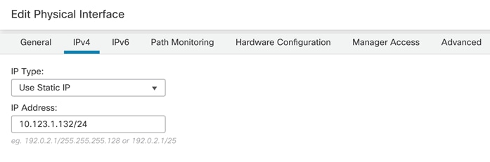
Step 7. Click the pencil to edit G0/0, outside interface.
Step 8. Under Security Zone, select New and name the new security zone “outside_zone”
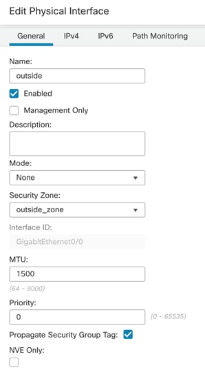
Step 9. Click IPv4 and from the IP Type drop-down list, select Use Static IP. Enter an IP address and subnet mask.
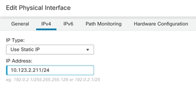
Step 10. Click OK to accept the changes.
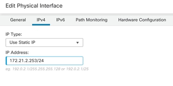
Step 11. Click the pencil to edit G0/1, inside interface.
Step 12. Under Security Zone, select New and name the new security zone “inside_zone”
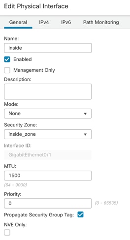
Step 13. Click IPv4 and from IP Type drop-down list, select Use Static IP. Enter an IP address and subnet mask.
Step 14. Click OK to accept the changes.
Step 15. Repeat these steps to configure interfaces for all the FTDv devices.
Procedure 2. Configure default route for outside interface
Step 1. In the main window, click Routing.
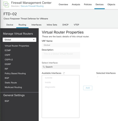
Step 2. Click Static Routing in the left pane.
Step 3. Click +Add Route.
Step 4. Select IPv4, and under Interface select outside.
Step 5. Under Available Network, select any-ipv4 and click Add to add the network to Selected Networks.
Step 6. Enter the gateway IP address and click OK to accept.
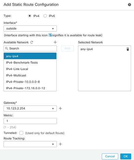
Step 7. Click Save to save the routing changes.
Step 8. Repeat these steps to configure the default gateways for all the FTDv devices.
Procedure 3. Deploy the interface and routing changes
Step 1. From the main menu, select Deploy.
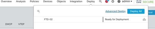
Step 2. Select Deploy All to push the interface and routing changes to all the FTDv appliances.
Note: Once the configuration deployment finishes, you can test the FTDv connectivity by logging into the VM console and pinging from the FTDv.
Cisco Secure Firewall Threat Defense (FTD) provides a very comprehensive set of policies. The intent of this document is not to explain all the firewall policies that FTD has to offer. The FW configuration explained in this section will be limited to following:
● Create an Access Policy that ensures traffic from application virtual machines (VM) within the tenant environment is always permitted to access networks outside the firewall.
● Restrict incoming traffic on the firewall so that only traffic destined for applications hosted within the tenant is allowed on limited set of ports.
● Set up Network Address Translation (NAT) to allow all traffic originating from the tenant network to use the external IP address of the FTDv appliance.
● Implement NAT rules to permit external traffic to reach a tenant application VMs without changing the IP address.
● Enable recommended Intrusion Prevention System (IPS) and Intrusion Detection System (IDS) policies on the FTDv to enhance security.
● Turn on the advised Malware protection policies on the FTDv to safeguard against malicious software threats.
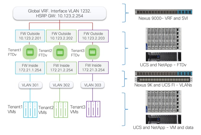
Tenant Setup
In the configuration examples below, various policies will be defined for the following Tenant:
Tenant Name: Tenant2
Tenant private IP subnet: 172.21.2.0/24
Tenant Application: WordPress
Tenant VMs:
● Tenant2-WP-APP – 172.21.2.61 – Allowed Traffic on FW: SSH, HTTP.
● Tenant2-WP-DB – 172.21.2.62 – Allowed Traffic on FW: SSH.
Access Control:
● Allow all tenant VMs to access outside networks including the Internet.
● Allow enterprise clients to access both WordPress VMs directly (without NAT) using SSH for management.
● Allow outside networks to access Tenant2-WP-App VM using HTTP to access WordPress.
NAT:
● Translate Tenant 2 VM IP addresses in subnet 172.21.2.0/24 to FTDv appliance outside interface to allow VMs access outside networks and Internet.
● Do not translate VM IP addresses 172.21.2.61 and 172.21.2.62 for SSH and HTTP access so corporate clients can access the application VMs using their private IP addresses.
Access Control Policy
A base access control policy, Base_Block_All_Traffic was previously defined when adding FTDv instances to FMC. This policy is applied to all the FTDv instances configured in FMC and includes common access policies that apply to all the tenants.
In the following procedures:
● The base access control policy is modified to allow all tenant VMs to access the Internet.
● Tenant specific access control policies are defined to allow you access applications hosted within the tenant. These policies will use the base access control policy, Base_Block_All_Traffic, as their base policy.
Procedure 1. Modify Base_Block_All_Traffic policy
In this procedure, base access control policy is modified to permit tenant traffic to always go out of the firewall.
Step 1. Log into the FMC management console and click Policies > Access Control.
Step 2. Click the pencil to edit the Base_Block_All_Traffic policy.
Step 3. Click +Add Rule.
Step 4. Provide a name and from the Insert drop-down list, select into Default.
Step 5. Add inside_zone to Source Zones and outside_zone to Destination Zones.

Step 6. Click Networks and add “any” to both Source Networks and Destination Networks.
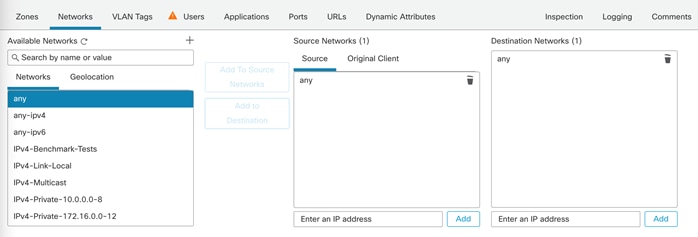
Step 7. Click Add to finish adding the rule.
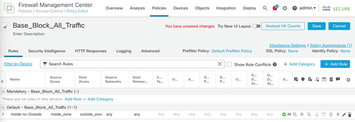
Step 8. Click Save to save changes.
Step 9. From the main menu, select Deploy.
Step 10. Select Deploy All to push the changes to all the FTDv appliances.
Procedure 2. Access Policy to allow Tenant Application Traffic
In this procedure, Access Control policies will be created for the individual tenants. These Access Control Policies will use Base_Block_All_Traffic policy as the base policy and contain tenant specific modifications to allow access to application and VMs hosted within the tenant.
Step 1. Log into the FMC management console and click Policies > Access Control.
Step 2. On the top right, click New Policy.
Step 3. Provide a name and from the Select Base Policy drop-down list, select Base_Block_All_Traffic.
Step 4. Under Targeted Devices, add the FTDv (where this policy will be applied) to the Selected Devices list.
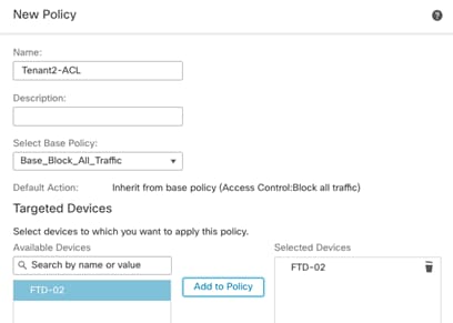
Step 5. Click Save.
Note: If you receive a warning that device is already assigned to Base_Block_All_Traffic, click Yes to continue assigning the device to the newly created policy.
Step 6. Click Add Rule on the top right to add a new rule to allow SSH to WordPress App server.
Step 7. Provide a name and under Insert drop-down, select into Default.
Step 8. Add outside_zone to Source Zones.
Step 9. Add inside_zone to Destination Zones.
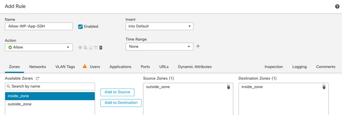
Step 10. Click Networks on the main screen.
Step 11. Click + next to Available Networks to add a network object and select Add Object.
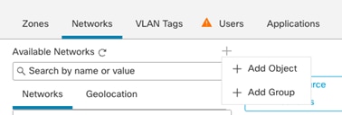
Step 12. Provide Name and Host information and click Save.
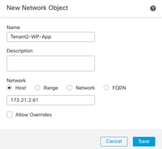
Step 13. Under Networks, select the newly created network object and click Add to Destination.
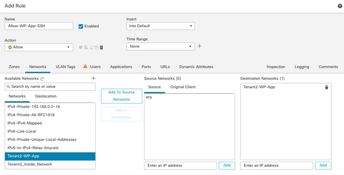
Step 14. Click Ports in the main window.
Step 15. In the search box, type SSH, select SSH and click Add to Destination.
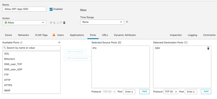
Step 16. Click Add to finish adding the rule.
Step 17. Repeat steps 1 - 16 to add another rule to allow HTTP traffic to the WordPress App server. This rule can be named Allow-WP-App-HTTP.
The next steps add a rule in the firewall to allow SSH traffic to the WordPress DB server.
Step 18. Click Add Rule on the right to add a new rule.
Step 19. Provide a name and under Insert drop-down, select into Default.
Step 20. Add outside_zone to Source Zones.
Step 21. Add inside_zone to Destination Zones.
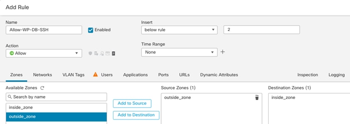
Step 22. Click Networks on the main screen.
Step 23. Click + next to Available Networks to add a network object. Select Add Object.
Step 24. Provide Name and Host information and click Save.
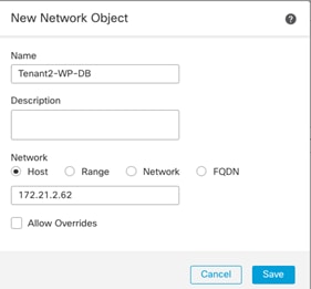
Step 25. Under Networks, select the newly created network object.
Step 26. Click Add to Destination.
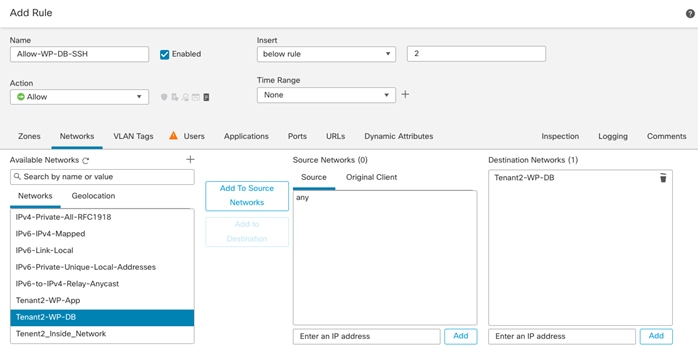
Step 27. Click Ports in the main window.
Step 28. In the search box, type SSH. Click SSH and click Add to Destination.
Step 29. Click Add to finish adding the rule.
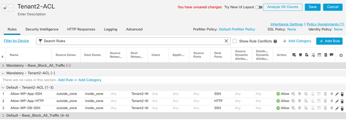
Step 30. Click Save to save the ACL.
Step 31. Repeat steps 18 – 30 to define the access control policies for all the FTDv appliances.
Step 32. Select Deploy and select Deploy All to push the configuration to all the FTDv instances.
NAT Policy
A NAT policy per tenant is created to allow tenant specific network address translations. The following two type of NAT policies are defined:
In the following procedures:
● An Auto-NAT rule is created for every tenant which provides all VMs access to outside networks, including the Internet.
● Application or VM specific static address translations are defined to allow outside clients to access the VMs or services inside tenant network using the non-translated private IP addresses of the VMs.
Procedure 1. Add Auto NAT rule to allow tenant traffic access outside networks
In this procedure, a NAT rule is configured to allow all tenant VMs access external networks. All VM IP addresses in the tenant subnet (172.21.2.0/24) will be translated to use the FTDv outside interface IP address.
Step 1. Log into the FMC management console and click Devices > NAT.
Step 2. Select New Policy > Threat Defense NAT.
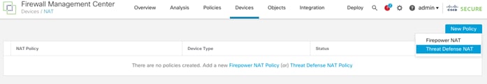
Step 3. Provide a name for the policy (Tenant2-NAT-Policy) and under Targeted Devices, add the FTDv (where this policy will be applied) to the Selected Devices list.
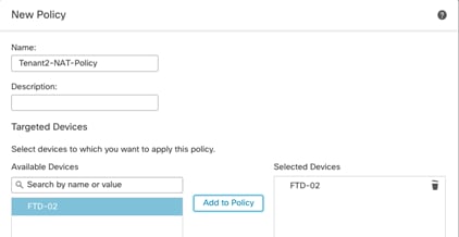
Step 4. Click Save.
Step 5. From the Rules tab, click Add Rule on the right.
Step 6. Under the NAT Rule, select Auto NAT Rule.
Step 7. From the Type drop-down list, select Dynamic.
Step 8. Click Interface Objects on the main screen.
Step 9. Add inside_zone to Source Interface Objects.
Step 10. Add outside_zone to Destination Interface Objects.
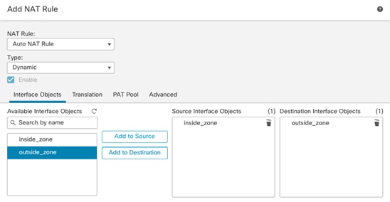
Step 11. Click Translations in the main window. Under the Translation tab, click + next to Original Source to add a Network Object.
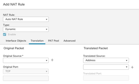
Step 12. Provide a name for tenant network and subnet information and click Save.
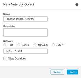
Step 13. From the Original Source drop-down list, select the Network Object just created.
Step 14. From the Translated Source drop-down list, select the Destination Interface IP.
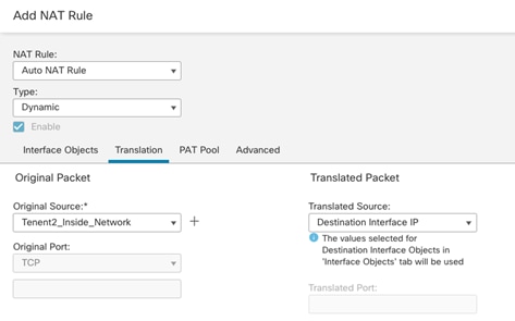
Step 15. Click OK to complete the rule.
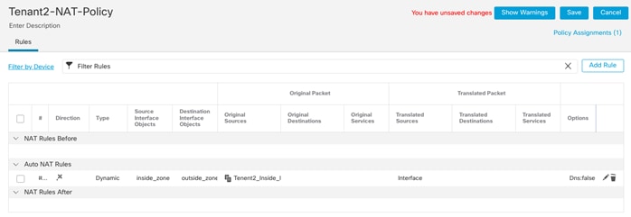
Procedure 2. Add NAT rule to allow App and DB server NAT bypass
In this procedure, two NAT rules are configured to make sure tenant WordPress App and DB server IP addresses are not translated for SSH and HTTP traffic. This procedure is a continuation from the last procedure.
Step 1. Click Add Rule to add SSH NAT rule for WordPress Application server.
Step 2. From the NAT Rule drop-down list, select Manual NAT Rule.
Step 3. Leave Insert In Category set to NAT Rules Before.
Step 4. Under Type, select Static.
Step 5. Make sure the rule is enabled.
Step 6. Select Interface Objects from the main window.
Step 7. Add inside_zone to Source Interface Objects and outside_zone to Destination Interface Objects.
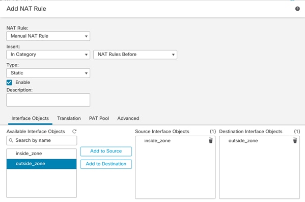
Step 8. Click Translation on the main screen.
Step 9. Select WordPress application server object (Tenant2-WP-App) as Original Source.
Step 10. Make sure Original Destination is set to Address.
Step 11. Select WordPress application server object (Tenant2-WP-App) as Translated Destination to make sure the source address remains unchanged.
Step 12. Select SSH as Original Source Port and Translated Source Port.
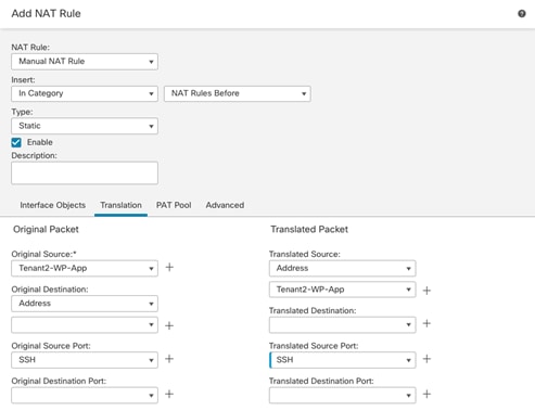
Step 13. Click OK to add the NAT rule.
Step 14. Repeat steps 1 – 13 to add a similar rule for HTTP translation for WordPress App server as shown below:
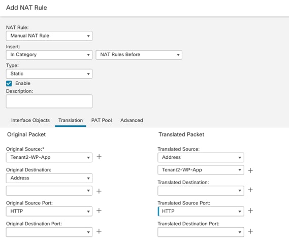
Step 15. Click Add Rule to add an SSH NAT rule for WordPress DB server.
Step 16. From the NAT Rule drop-down list, select Manual NAT Rule.
Step 17. Leave Insert In Category set to NAT Rules Before.
Step 18. Under Type, select Static.
Step 19. Make sure the rule is enabled.
Step 20. Select Interface Objects from the main window.
Step 21. Add inside_zone to Source Interface Objects and outside_zone to Destination Interface Objects.
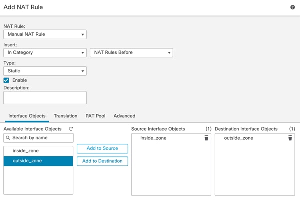
Step 22. Click Translation on the main screen.
Step 23. Select WordPress application server object (Tenant2-WP-DB) as Original Source.
Step 24. Make sure Original Destination is set to Address.
Step 25. Select WordPress application server object (Tenant2-WP-DB) as Translated Destination.
Step 26. Select SSH as Original Source Port and Translated Source Port.
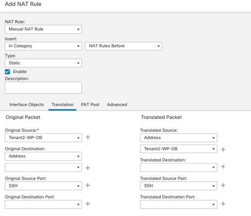
Step 27. Click OK to add the NAT rule.
Step 28. Verify all the NAT rules are in place as defined.
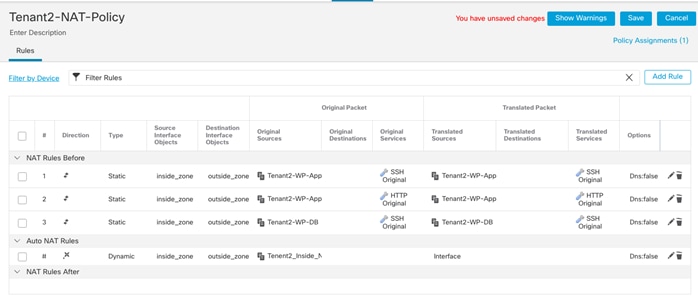
Step 29. Click Save to save the NAT rules.
Step 30. Repeat steps 15 - 29 to add NAT policies for all the tenants.
Step 31. Select Deploy in the main window and click Deploy All.
At this time, the tenant VMs should be able to browse the Internet and from outside the firewall, clients should be able to SSH into the WordPress App and DB servers. The clients should also be able to access the WordPress application HTTP server.
Note: In customer deployments, WordPress application will be accessed over HTTPS therefore firewall configuration will need to be adjusted to allow HTTPS port. Since this is a lab environment, HTTPS access was not configured for the WordPress application.
IPS Policy
You can use intrusion rule recommendations to associate the operating systems, servers, and client application protocols detected on their network with rules specifically written to protect those assets. This allows you to tailor your intrusion policy to the specific needs of the monitored network.
The system makes an individual set of recommendations for each intrusion policy. It typically recommends rule state changes for standard text rules and shared object rules. However, it can also recommend changes for preprocessor and decoder rules.
To enable Cisco recommended IPS rules, follow this FMC configuration guide.
Malware Protection Policy
Advanced Malware Protection (AMP) for Firepower can detect, capture, track, analyze, log, and optionally block the transmission of malware in network traffic. In the FMC web interface, this feature is called malware defense, formerly called AMP for Firepower. Advanced Malware Protection identifies malware using managed devices deployed inline and threat data from the Cisco cloud.
To enable Malware protection and to configure File and Malware protection according to product best practices, follow this FMC configuration guide.
Deploy Secure Network Analytics
This chapter contains the following:
● Deploy Secure Network Analytics
Cisco Secure Network Analytics (formerly known as Stealthwatch) is a comprehensive network traffic analysis and network detection and response solution that uses telemetry from the existing network infrastructure to provide deep visibility into network activity and detect threats across private networks, public clouds, and even encrypted traffic. The solution continuously analyzes network activities to create a baseline of normal network behavior. It then uses this baseline, along with non–signature-based advanced analytics that include behavioral modeling and machine learning algorithms, as well as global threat intelligence to identify anomalies and detect and respond to threats in real-time. Secure Network Analytics performs monitoring of network traffic using data collected from NetFlow devices across the network acting as a complement to the string based IPS detection of Secure Firewall.
In this validated design, Secure Network Analytics without a Datastore will be installed. In the lab environment, following two virtual appliances are installed:
● 1 Secure Network Analytics Manager
● 1 Secure Network Analytics Flow Collector
For scalability and other considerations, refer to installation guide and follow the design recommendations in the guide.
Manager
The Secure Network Analytics Manager aggregates, organizes, and presents analyses from up to 25 Flow Collectors, and other sources. It uses graphical representations of network traffic, identity information, customized summary reports, and integrated security and network intelligence for comprehensive analysis.
Flow Collector
The Flow Collector collects and stores enterprise telemetry types such as NetFlow from existing infrastructure such as routers, switches, firewalls, endpoints, and other network infrastructure devices. The telemetry data is analyzed to provide a complete picture of network activity.
System Requirements
This section covers some of the common requirements for installation of Secure Network Analytics components. For detailed requirements, go to: Virtual Edition Appliance Installation Guide.
VMware
VMware requirements for deploying Secure Network Analytics:
● Compatibility: VMware 7.0 or 8.0. VMware 7.0 is being deployed in the environment.
● Operating System: Debian 11 64-bit
● Network Adapter: The VMXNET3 Adapter Type is recommended for best performance.
● Live migration: Live migration (for example, with vMotion) is not supported.
● Snapshots: Virtual machine snapshots are not supported.
Compute and Memory
To determine the minimum resource allocations for the virtual edition of Manager, determine the number of concurrent users expected to log in to the Manager. Refer to the following specifications to determine your resource allocations:
Table 6. Manager - Virtual Edition
| Concurrent Users |
Required CPUs |
Required Memory |
Required Minimum Storage |
Flows per second |
Internal Hosts |
| Up to 9* |
6 |
40GB |
200GB |
Up to 100,000 |
100,000 |
| Over 10 |
12 |
70GB |
480GB |
Over 100,000 |
250,000 |
*Deployed in the lab during validation
To determine your resource requirements for the Flow Collector Virtual Edition, make sure to calculate the flows per second expected on the network and the number of exporters and hosts it is expected to monitor. Refer to the installation guide for calculating flows per second.
Table 7. Flow Collector Virtual Edition without Data Store
| Concurrent Users |
Required CPUs |
Required Memory |
Required Minimum Storage |
Interfaces |
Exporters |
Internal Hosts |
| Up to 10,000* |
2 |
24GB |
600GB |
Up to 65535 |
Up to 1024 |
25,000 |
| Up to 30,000 |
6 |
32GB |
900GB |
Up to 65535 |
Up to 1024 |
100,000 |
| Up to 60,000 |
8 |
64GB |
1.8TB |
Up to 65535 |
Up to 2048 |
250,000 |
| Up to 120,000 |
12 |
128GB |
3.6TB |
Up to 65535 |
Up to 4096 |
Over 250,000 |
*Deployed in the lab during validation
Network
For each Manager and Flow Collector that you deploy, assign a routable IP address to the eth0 management port. In this deployment, IB-Mgmt (VLAN 1231) network was used to deploy virtual manager and flow collector.
Firewall Rules
If there is a firewall separating the flow collector and manager, various ports need to be opened as covered in Communication Ports and Protocols in the installation guide. In the lab, both flow collector and manager were on the same in-band management network therefore firewall configuration was not needed.
Deploy Secure Network Analytics
Virtual Manager
Procedure 1. Download and install the virtual manager software
Step 1. Download the software from this link.
Step 2. Follow the installation steps in installation guide. Go to Installing a Virtual Appliance Using vCenter (ISO) and under All Other Appliances, click Installing the Virtual Appliance.
Note: During VM deployment, remember to click New SCSI controller to expand the configuration options and from the Change Type drop-down list, select LSI Logic SAS. Failure to select LSI Logic SAS can cause the virtual appliance deployment to fail.
Flow Collector
Procedure 1. Download and install the flow collector software
Step 1. Download the software from software download.
Step 2. Follow the installation steps in installation guide. Go to Installing a Virtual Appliance Using vCenter (ISO) and under All Other Appliances, click Installing the Virtual Appliance.
Note: During VM deployment, remember to click New SCSI controller to expand the configuration options and from the Change Type drop-down list, select LSI Logic SAS. Failure to select LSI Logic SAS can cause the virtual appliance deployment to fail.
Procedure 2. Configure the network for manager and flow collector
Step 1. Follow the installation steps in System Configuration Guide. Go to Configuring Your Secure Network Analytics System and follow the instructions to provide various configuration parameters such as address, hostname etc.
Step 2. Open the VMware remote console for both the manager and flow collector.
Step 3. Log into the VM using default username and password for logging into the appliance is: sysadmin/lan1cope.
Step 4. At the command prompt, type SystemConfig to start configuration. When logging in for the first time, the system will automatically launch the system configuration.
Step 5. Provide the hostname, domain, and IP information.
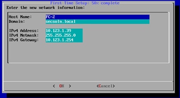
Step 6. Click OK and then OK again to reboot the system for changes to take effect.
Procedure 3. Configuring the virtual manager
Step 1. When the central manager VM reboot completes, point your browser to IP address of the virtual manager: https://<network analytics manager IP>.
Step 2. Use the default username/password of admin/lan411cope to log into the appliance.
Step 3. Click Continue on initial welcome screen.
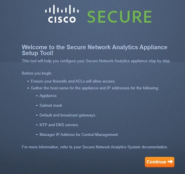
Step 4. Change the default passwords for admin, sysadmin, and root. The current root and sysadmin passwords are lan1cope. The current password for admin is lan411cope. Click Next.
Step 5. Verify the network interface information and click Next.
Step 6. Provide the network domain that needs to be monitored and set the Manager Domain Type to Non-Data Store.
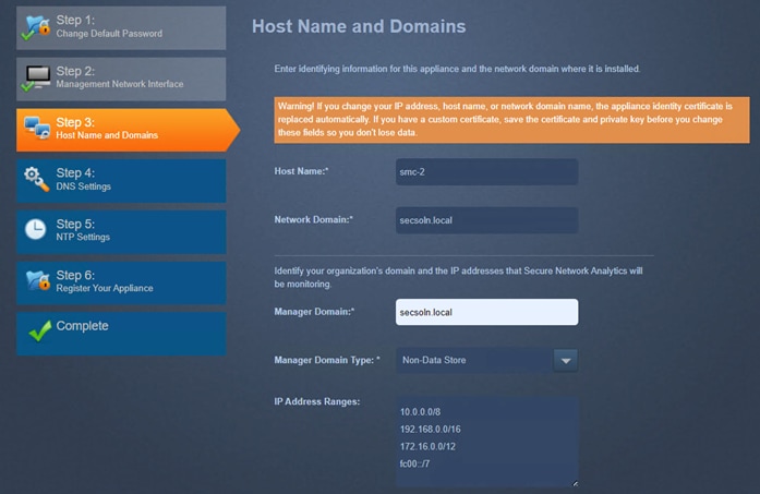
Step 7. Adjust the IP address ranges to be monitored (if needed). Click Next.
Step 8. Click + to add DNS server(s). Click Next.
Step 9. Click + to add NTP server(s). Click Next.
Step 10. Verify the information and click Restart and Proceed.
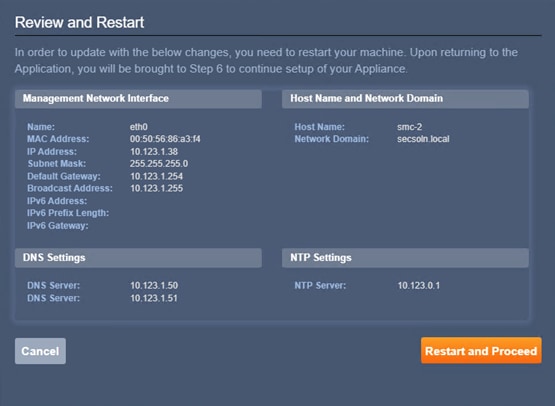
Step 11. Wait for the appliance reboot to complete and services to initialize. It might take a while for services to initialize. When the appliance completely boots up, log in using the new admin password.
Step 12. Press Continue on the welcome screen.
The setup wizard will jump to Step 6 to confirm the IP address of the Central Manager.
Step 13. Click Save. Click Go to Dashboard to start using the Central Manager.
Note: For in-depth configuration guidance, follow the installation steps in the System Configuration Guide.
Procedure 4. Configuring the Flow Collector
Step 1. When the flow collector VM reboot completes, point your browser to IP address of the virtual manager: https://<network analytics manager IP>.
Step 2. Use the default username/password of admin/lan411cope to log into the appliance.
Step 3. Click Continue on the welcome screen.
Step 4. Change the default passwords for admin, sysadmin, and root. The current root and sysadmin passwords are lan1cope. The current password for admin is lan411cope. Click Next.
Step 5. Verify the network interface information and click Next.
Step 6. Verify the hostname and network domain and click Next.
Step 7. Click + to add DNS server(s). Click Next.
Step 8. Click + to add NTP server(s). Click Next.
Step 9. Verify the information and click Restart and Proceed.

Step 10. Wait for some time for the appliance reboot to complete and services to initialize. When the appliance completely boots up, log in using the new admin password.
Step 11. Press Continue on the welcome screen.
Step 12. The setup wizard will go to Step 6. Add the IP address of the Central Manager.
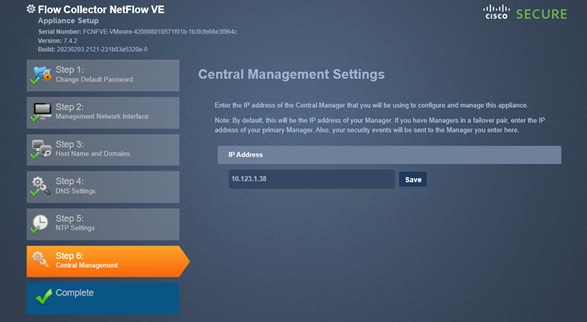
Step 13. Click Save. On the certificate verification screen, click Yes after verifying the Fingerprint.
Step 14. Enter the Central Manager admin username and password and click Next.
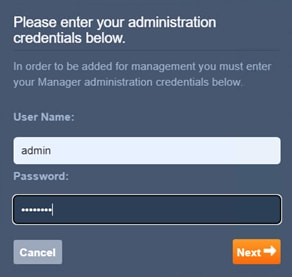
Step 15. From the Domain drop-down list, select the domain to monitor.
Step 16. Enter NetFlow port 2055 in the Flow Collection Port.
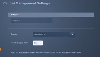
Step 17. Click Next.
Step 18. Click Go to Central Management.
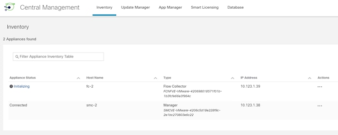
Note: It will take time for the flow collector to be initialized and show up as connected.
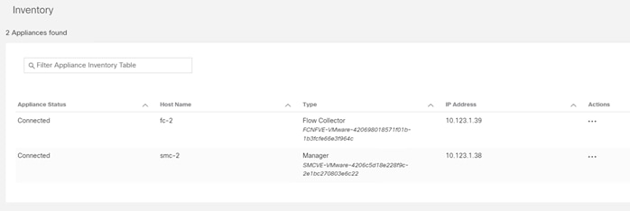
Step 19. (Optional) On the Central Manager web console, go to Smart Licensing tab to add license. All new setups come with a 90-day evaluation license.
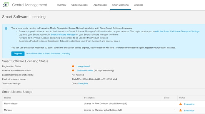
Secure Network Analytics is set up and ready to receive the NetFlow records from the network. The next step is to configure NetFlow exporters in the environment.
NetFlow is enabled on the following devices to provide full infrastructure visibility:
● Cisco Nexus 93600CD-GX
● Cisco FTDv appliances
● VMware ESXi hosts
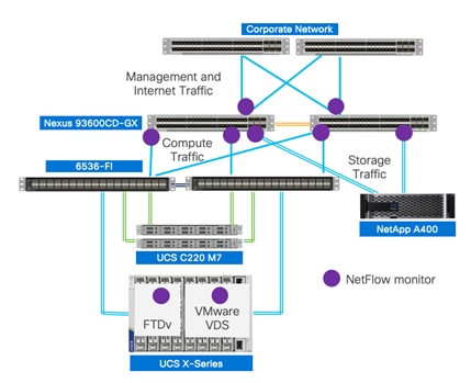
NetFlow records are exported to the Flow Collector which receives, decodes, and stores flow data. Configurations and traffic analysis are performed via the Management Console including setting up user accounts, configuring Flow Collectors, and setting up alerts.
Procedure 1. Configure NetFlow on Cisco Nexus switches
On Cisco Nexus 93600CD-GX switches, NetFlow is monitored on VPCs for Cisco UCS, NetApp controllers, and management/enterprise connections.
Step 1. Enable NetFlow feature and create an exporter to export NetFlow records to the flow collector.
feature netflow
flow exporter StealthWatch
destination 10.123.1.39 use-vrf management (IP address of flow collector)
transport udp 2055
source mgmt0
version 9
template data timeout 20
Step 2. Create a NetFlow record and include the fields to export.
flow record NetFlow-Record
match ipv4 source address
match ipv4 destination address
match ip protocol
match transport source-port
match transport destination-port
collect transport tcp flags
collect counter bytes long
collect counter packets long
Step 3. Create a flow monitor and apply to UCS, NetApp and enterprise/management network port-channels.
record NetFlow-Record
exporter StealthWatch
interface port-channel11
description UCS FI-A
ip flow monitor NetFlow-Monitor input
interface port-channel12
description UCS FI-B
ip flow monitor NetFlow-Monitor input
interface port-channel13
description NetApp contoller 1
ip flow monitor NetFlow-Monitor input
interface port-channel14
description NetApp contoller 2
ip flow monitor NetFlow-Monitor input
interface port-channel103
description Enterprise and Management network
ip flow monitor NetFlow-Monitor input
Procedure 2. Configure NetFlow on Firewall Threat Defense Virtual (FTDv)
In Firewall Management Center, the FlexConfigs feature is used to export NetFlow to Flow Collector. A FlexConfig policy is a container of an ordered list of objects. Each object includes CLI-based configuration commands. FlexConfig generates a sequence of CLI commands that are deployed to the assigned devices.
Step 1. Log into Firewall management center GUI.
Step 2. Navigate to Objects > Object Management and from the left column, select FlexConfig > Text Object.
Step 3. In the search box on the right, type netflow to filter the objects.
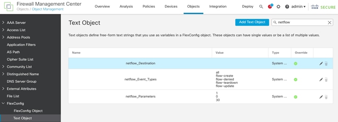
Step 4. Click the pencil to edit the netflow_Destination.
Step 5. Make sure variable type is Multiple and change the variable count to 3. Enter the FTDv source interface, IP address of flow collector, and NetFlow port (in order) and click Save.
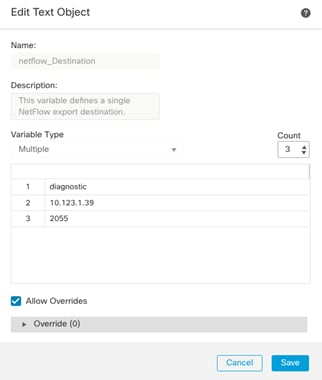
Note: Make sure Diagnostics0/0 interface is configured in IB-Mgmt (VLAN 1231), which is the same network where Flow Collector is installed.
Step 6. Click the pencil icon next to neflow_Event_Types. Leave all in the list and remove the other values (reducing the count to 1 should achieve this). Click Save.
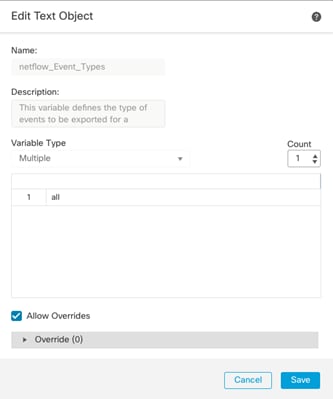
Step 7. Leave the NetFlow parameters unchanged.
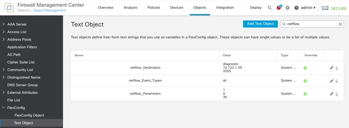
Step 8. From the left column, select FlexConfig > FlexConfig Object.
Step 9. In the search box on the right, type netflow to filter the objects.
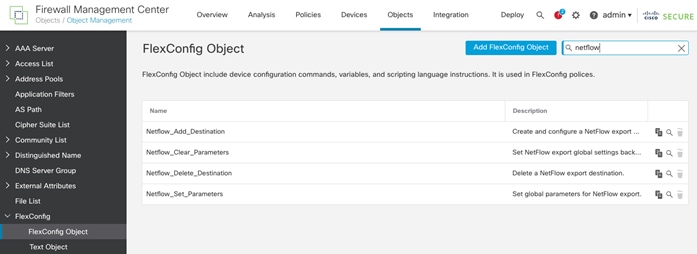
Step 10. Create a copy of Netflow_Add_Destination.
Step 11. Provide a name and click Save.
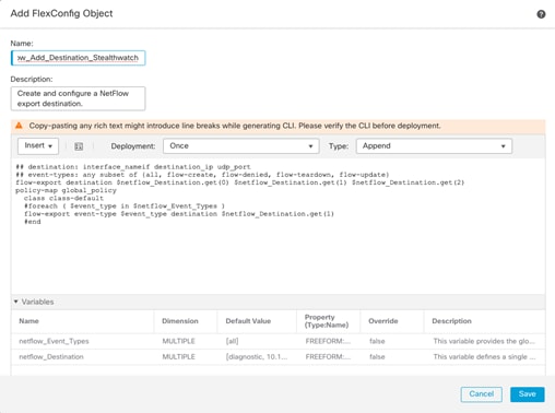
Note: You will need to refresh the screen for the object to display.
Step 12. Create a copy of Netflow_Set_Parameters.
Step 13. Provide a name and click Save.
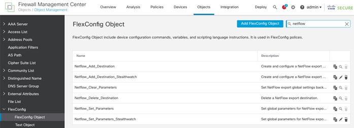
Note: A copy of the policies was created in case some parameters need to be updated later.
Step 14. Navigate to Devices > FlexConfig.
Step 15. Click New Policy.
Step 16. Provide a name and add the FTDv devices where this policy will be applied.
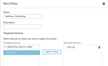
Step 17. Click Save.
Step 18. Select Devices > Platform Settings.
Step 19. Create New Policy > Threat Defense Settings.
Step 20. Provide a name and add the FTDv instances where this policy will be applied.
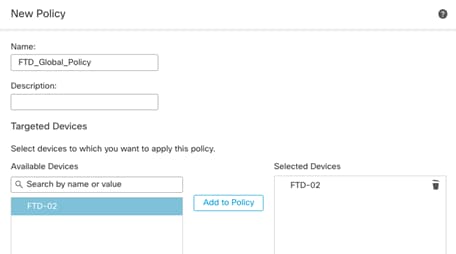
Step 21. Click Save.
Step 22. Type NetFlow in the Available FlexConfig box. The two policies defined in the previous steps should be visible.
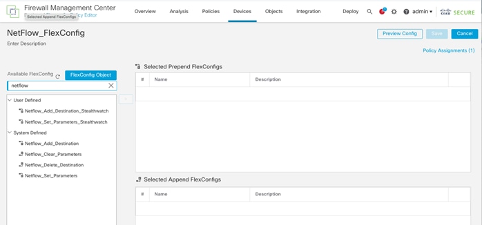
Step 23. Click > to add both policies to Selected Append FlexConfig.
Step 24. Click Save and then preview configuration if needed.
Step 25. Navigate to Deploy > Deploy All. View the warning about lack of extensive validation for FlexConfig and then click Proceed with Deploy.
Step 26. If there is traffic through the firewall, you can open Secure Network Analytics manager GUI and navigate to Configure > Exporters.
In a few minutes, FTDv will be added as an exporter.
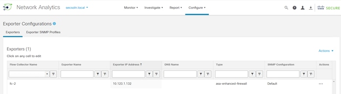
VMware
Follow these steps to enable NetFlow on the VMware VDS. NetFlow configuration will be applied to all the ESXi hosts.
Procedure 1. Enable NetFlow on VMware VDS
Step 1. Log into the VMware vCenter.
Step 2. On the vSphere Client Home page, click Networking and navigate to the distributed switch.
Step 3. From the Actions menu, select Settings > Edit NetFlow.
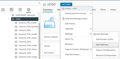
Step 4. Type the Collector IP address and Collector port of the NetFlow collector.
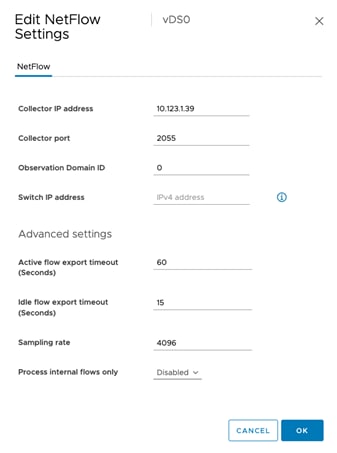
Step 5. Click OK.
Step 6. You can open Secure Network Analytics manager GUI and navigate to Configure > Exporters.
In a few minutes, all the ESXi hosts associated with the VDS will be added as exporters.
Deploy Intel Confidential Computing
This chapter contains the following:
● Intel Total Memory Encryption
● Intel Software Guard Extensions (SGX)
Intel Confidential Computing is a security technology built into Intel processors that enables protected execution of sensitive data within a hardware-isolated environment called a Trusted Execution Environment (TEE). This TEE acts as a secure enclave, shielding data and computations from unauthorized access, even from privileged software like the operating system or the hypervisor.
Enterprise services often run in a hybrid and multi-cloud environment, and it is critical to protect enterprise applications when working with confidential data such as username, password, database credentials, and API keys, when interacting with third-party services, credentials for service-oriented architecture communication, and more. Intel’s Xeon Scalable processor has multiple security features that can help significantly boost the security posture of a Zero Trust solution architecture, including Intel Total Memory Encryption (Intel TME) for memory encryption and Intel Software Guard Extensions (Intel SGX) facilitating confidential computing.
Intel TME can encrypt the entirety of physical memory of a physical server system. This capability typically is enabled in the very early stages of the boot process with a small setting in the UEFI/BIOS. After it is configured and locked, the CPU is responsible for encrypting all data into the system memory.
Intel TME capability is transparent to software such as operating systems, hypervisors, or containers, applications, and micro services. It does not require any specific Linux kernel support. Overall, the performance impact of this capability is negligible to workloads.
Procedure 1. Enable Total Memory Encryption (TME)
To enable Intel TME, in the BIOS policy under Trusted Platform portion of the BIOS settings, set Total Memory Encryption (TME) to enabled.
To enable Intel TME in an existing FlexPod setup, follow these steps.
Step 1. Log into Cisco Intersight. Navigate to Infrastructure Service and click Policies in the left column.
Step 1. Search for the BIOS policies. Click … next to the applicable BIOS policy and click Edit.
Step 2. Verify the BIOS policy is attached to correct servers and click Next.
Step 3. Expand the Trusted Platform portion of the settings.
Step 4. Change Total Memory Encryption (TME) to enabled.
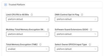
Step 5. Click Save and Deploy.
Step 6. The server profiles tied to this BIOS policy will need to be rebooted for the changes to take effect.
Intel Software Guard Extensions (SGX)
Intel SGX is a set of instructions incorporated in Intel Xeon Scalable processor. Software developers can place security-sensitive codes and data into an Intel SGX enclave, which is then executed in a CPU protected region. Traditionally, when a system’s BIOS, hypervisor, or operating system is compromised by a malicious attack, the attacker’s code can gain visibility and access to everything higher in the system stack, such as applications and data.
VMware vSphere enables you to configure Virtual Intel Software Guard Extensions (vSGX) for virtual machines. vSGX enables virtual machines to use Intel SGX technology if available on the hardware. To use vSGX, the ESXi host must be installed on an SGX-capable CPU such as Intel Xeon scalable processor and SGX must be enabled in the BIOS of the server. The VMware vSphere Client can then be used to enable SGX for a virtual machine.
To view a list of all Intel CPU that support SGX, follow this link.
vSGX Requirements
To use vSGX, the vSphere environment must meet these requirements:
● VMware ESXi running in the host is ESXi 7.0 or later.
● The virtual machine uses EFI firmware.
● The virtual machine hardware version is 17 or later.
● The guest VM is running either a major Linux distribution, Windows Server 2016 (64-bit) or later, or Windows 10 (64-bit) or later.
For more details, go to: Enable vSGX on a Virtual Machine.
vSGX restrictions
To use vSGX, the vSphere environment must meet these requirements:
Some operations and features are not supported for a virtual machine when vSGX is enabled.
● Migration with Storage vMotion.
● Suspending or resuming the virtual machine.
● Taking snapshot of the virtual machine, especially if you take a snapshot of the virtual machine memory.
● Fault Tolerance
vSGX Deployment in VMware environment
To enable vSGX follow these steps.
Procedure 1. Enable SGX in BIOS Policies
Step 1. Log into Cisco Intersight. Navigate to Infrastructure Service and click Policies in the left column.
Step 2. Search for the BIOS policies. Click … next to the applicable BIOS policy and click Edit.
Step 3. Verify the BIOS policy is attached to correct servers and click Next.
Step 4. Expand the Trusted Platform portion of the settings.
Step 5. Change Total Memory Encryption (TME) to enabled.
Step 6. Change Software Guard Extensions (SGX) to enabled.
Step 7. Change SGX Write Enable to enabled.
Step 8. Expand the Processor section of the settings.
Step 9. Select a size under PRMRR Size.
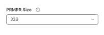
Note: This is the size of the protected region in the system DRAM. The maximum size of the PRMRR field in the BIOS configuration will match the amount of SGX Enclave Capacity value for the Intel CPU being utilized.
Step 10. Click Save and Deploy.
Step 11. The server profiles tied to this BIOS policy will need to be rebooted for the changes to take effect.
Procedure 2. Verify SGX configuration in ESXi server
Step 1. SSH into the ESXi host where SGX was enabled.
Step 2. Run the following command to verify SGX is enabled:
vsish -e get /hardware/cpu/sgxInfo
[root@AB03-ESXi-04:~] vsish -e get /hardware/cpu/sgxInfo
SGX Global information {
SGX state: 7 -> Enabled
SGX FLC Mode: 2 -> MSRs are writeable
Total EPC Size (pages):16675839
Free EPC Pages:16544767
Unused EPC Pages:16544767
Number of EPC regions:2
Maximum Enclave size when not in 64bit (GB):2
Maximum Enclave size in 64bit (GB):67108864
EPC region information:[0]: EPC region {
Base:0x180c000000
Size (pages):8336383
NUMA node:0
}
[1]: EPC region {
Base:0x380c000000
Size (pages):8339456
NUMA node:1
}
[2]: EPC region {
Base:0x0
Size (pages):0
NUMA node:0
}
[3]: EPC region {
Base:0x0
Size (pages):0
NUMA node:0
}
[4]: EPC region {
Base:0x0
Size (pages):0
NUMA node:0
}
[5]: EPC region {
Base:0x0
Size (pages):0
NUMA node:0
}
[6]: EPC region {
Base:0x0
Size (pages):0
NUMA node:0
}
[7]: EPC region {
Base:0x0
Size (pages):0
NUMA node:0
}
SGX launch enclave public key hash:[0]: 0xa6053e051270b7ac
[1]: 0x6cfbe8ba8b3b413d
[2]: 0xc4916d99f2b3735d
[3]: 0xd4f8c05909f9bb3b
SGX remote attestation support:0
Note: In the output (above), Intel SGX feature is enabled in the system and the total EPC size is 16675839 pages, which means 64GB (1 page = 4K bytes; there are two processor with PRMRR set to 32GB) is available for use.
Procedure 3. Enable vSGX on a VM
To enable vSGX on a VM, follow the VMware guide. For example, to modify an existing Linux VM to support vSGX, follow these steps:
Step 1. Shutdown the VM.
Step 2. Right-click the VM and select Edit Settings…
Step 3. Under Virtual Hardware, expand Security Devices.
Step 4. To enable SGX, select the Enabled check box.
Step 5. Provide an Enclave page cache size (256 MB) value.
Step 6. Set the Launch control configuration to Locked or Unlocked.
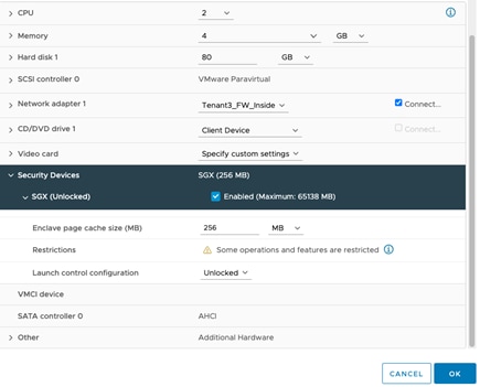
Step 7. Click OK.
Step 8. Power On the VM.
Step 9. Log into the VM and issue the following command to verify vSGX functionality is enabled:
[root@SGX-1 ~]# dmesg | grep -i sgx
[ 0.539478] sgx: EPC section 0x140000000-0x14fffffff
Note: The output shows EPC size is 0xFFFFFFF, which is 268,435,455 or 256MB.
Deploy a Tenant Application
This chapter contains the following:
● Application on Shared Infrastructure
● Application on Dedicated Infrastructure
In this chapter, WordPress, a sample two-tier application, is deployed on a tenant infrastructure. It is not intended to explain a detailed WordPress installation, but rather the focus is to show the following two different application deployment approaches:
● Application (both App and DB VMs) is deployed on common infrastructure datastore, but WordPress MariaDB database resides on an NFS share hosted in a tenant specific Storage Virtual Machine (SVM).
● Application VMs are deployed on tenant specific NFS datastore mounted on all the ESXi hosts. The database is stored inside the DB VM but is still separated from other tenants.
Application on Shared Infrastructure
Figure 8 shows the tenant that is being configured in this document.
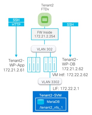
Procedure 1. Deploy and configure WordPress application
Step 1. Deploy two Linux VMs within the tenant. These two VMs are installed on shared infrastructure datastore infra_datastore_1 or infra_datastore_2.
Note: In this deployment, CentOS7 VMs were deployed to set up WordPress application.
Step 2. Install WordPress application such that Tenant2-WP-App VM contains httpd and php components of the application and the Tenant2-WP-DB contains MariaDB server.
Step 3. On successful install of the application, verify the database directory:
[root@Tenant2-WP-DB]# mysql -u root -p -e "SELECT @@datadir;"
Enter password:
+-----------------+
| @@datadir |
+-----------------+
| /var/lib/mysql/ |
+-----------------+
Procedure 2. Prepare the database VM to mount tenant NFS share
In this procedure, a second interface is added to tenant DB VM and the tenant NFS share will be mounted.
Step 1. Log into vSphere and select the DB VM.
Step 2. Right-click and select Edit Settings…
Step 3. Click on ADD NEW DEVICE and select Network Adapter.
Step 4. Make sure Adapter Type is set to VMXNET 3 and select the tenant NFS port-group (VLAN 3302).
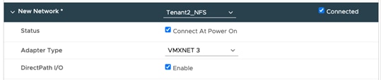
Step 5. Click OK.
Step 6. Log into Linux VM and configure the interface and IP address.
Step 7. Change the MTU on the interface to enable Jumbo MTU.
ifconfig <interface> mtu 9000 up
For example:
ifconfig ens224 mtu 9000 up
To Verify, ping with a large packet size:
ping 172.22.2.1 -M do -s 8972
To make the change permanent edit the configuration file. For example on CentOS:
/etc/sysconfig/network-scripts/ifcfg-Wired_connection_1
MTU="9000"
Step 8. Mount the NFS share from tenant SVM.
mkdir /mnt/mysql-data
mount -t nfs 172.22.2.1:/tenant2_nfs_1 /mnt/mysql-data/
For permanent mount:
Add following entry to /etc/fstab file:
172.22.2.1:/tenant2_nfs_1 /mnt/mysql-data nfs auto,noatime,nolock,bg,nfsvers=3,intr,tcp,actimeo=1800 0 0
Step 9. Move the mysql directory /var/lib/mysql to this newly mounted /mnt/mysql-data directory.
Note: This step requires familiarity with the Linux OS and MariaDB.
Step 10. Restart MariaDB and verify application operation.
Application on Dedicated Infrastructure
Figure 9 shows a tenant where a tenant dedicated NFS datastore is mapped to all the ESXi hosts. Instead of using a shared datastore (e.g. infra_datastore_1), tenant VMs are deployed using tenant specific datastore.
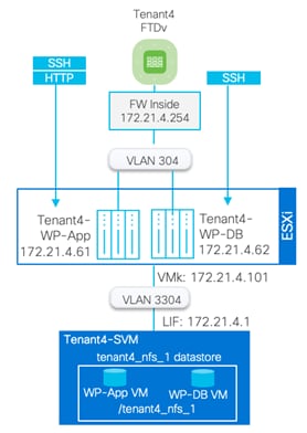
Procedure 1. Deploy and configure WordPress application
Step 1. Follow the previously explained procedure to mount a tenant NFS datastore to all ESXi hosts.
Step 2. Deploy two Linux VMs within the tenant. Instead of deploying these VMs on infra_datastore_1 or infra_datastore_2, the VMs are deployed on tenant specific datastore tenant4_nfs_1.
Step 3. Install WordPress application on these Linux VMs.
On successful installation of the application, the application VMs and their data are segregated from other tenants:
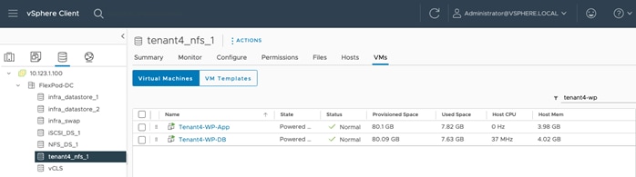
Deploy Secure Workload
This chapter contains the following:
● Secure Workload Agent Requirements
● Secure Workload Agent Installation on Tenant VMs
Secure workload provides the capability to do micro-segmentation in a highly flexible manner along with an in-depth visibility into the workloads. The enforcement agents provide an additional capability to enforce policies. Secure Workload offers two deployment options: on-premises and SaaS. The SaaS option, used in this validation, is a fully managed service that is suitable for any size customer. It has a low barrier to entry and a flexible pricing model, and it enables secure migration to cloud and multi-cloud environments.
Cisco Secure Workload offers visibility and enforcement agents that are installed on the workloads.
Secure Workload Agent Requirements
Use the Secure Workload compatibility matrix to find versions, capabilities, and packages requirements to install Secure Workload agents on various operating systems.
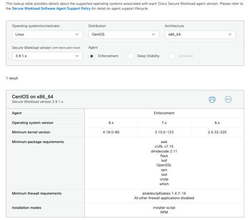
Secure Workload Agent Installation on Tenant VMs
To download and install Secure Workload Agent on the WordPress application VMs, follow these steps.
Procedure 1. Download the installer
Step 1. Log into Secure Workload GUI.
Step 2. Navigate to Workloads > Agents in the left menu.
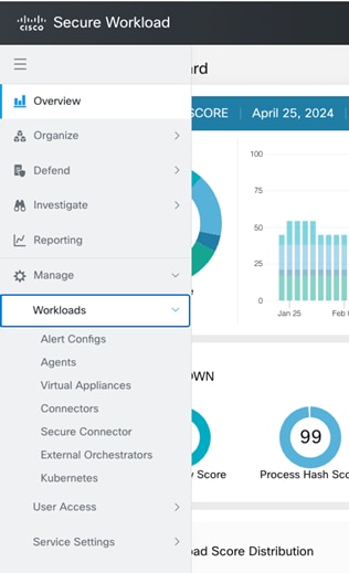
Step 3. From the main screen, select Installer.
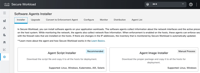
Step 4. Click Agent Script Install (Recommended).
Step 5. Select the Platform and click Show Supported Platforms to make sure an agent is available for your platform.
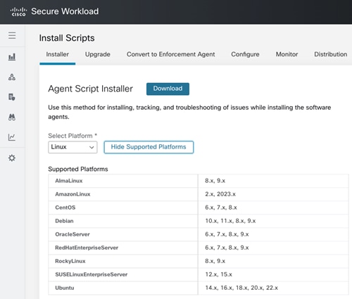
Step 6. Add HTTP proxy server and installer expiration information if needed.
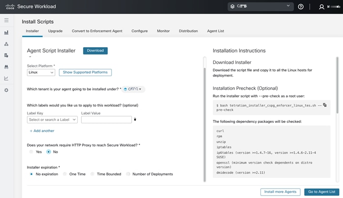
Step 7. Download the installation script and copy it to the application VMs where the agent will be installed.
Procedure 2. Install the Secure Workload agent on Linux VM
Step 1. Login to the application VMs using SSH.
Step 2. Perform the installation pre-check by running the following command as root user:
[root@Tenant2-WP-App ~]# bash tetration_installer_cspg_enforcer_linux_tes.sh --pre-check
#### Installer script run starts @ Thu Apr 25 18:40:47 EDT 2024: tetration_installer_cspg_enforcer_linux_tes.sh --pre-check
### Testing tet-sensor prerequisites on host "Tenant2-WP-App" (Thu Apr 25 18:40:47 EDT 2024)
### Script version: 3.9.1.1
Detecting dependencies
Checking for awk...(Deep Visibility, Enforcement) yes
Checking for dmidecode...(Deep Visibility, Enforcement) yes
Checking whether the dmidecode version >= 2.11...(Deep Visibility, Enforcement) yes; 3.2 detected
Checking for openssl version...(Deep Visibility, Enforcement)
Checking for iptables version...(Enforcement)
Checking whether IPv6 is enabled...(Enforcement) yes
Checking for ip6tables...(Enforcement) /usr/sbin/ip6tables
Checking whether the ip6tables works under user space...(Enforcement) yes
Checking for su support...(Deep Visibility, Enforcement) yes
Checking for curl...(Deep Visibility, Enforcement) /usr/bin/curl
Checking whether the curl version matches the libcurl version...(Deep Visibility, Enforcement) yes; 7.29.0 detected
Checking for tmpfile support...(Deep Visibility, Enforcement) yes
Checking for /usr/local/tet...(Deep Visibility, Enforcement) yes
### Pre-check Finished. Result: PASS
### tet-sensor prerequisites checking results on host "Tenant2-WP-App" (Thu Apr 25 18:40:53 EDT 2024)
Package/Service Result Detail
-------------------------------------------------
awk PASS
dmidecode PASS
unzip PASS
sed PASS
openssl PASS
iptables PASS
ipv6_enabled PASS
ip6tables PASS
su_support PASS
curl PASS
tmpfile_support PASS
installation_dir PASS
Cleaning up temporary files when exit
#### Installer script run ends @ Thu Apr 25 18:40:53 EDT 2024
Step 3. Perform the installation by running the following command as root user:
[root@Tenant2-WP-App ~]# bash tetration_installer_cspg_enforcer_linux_tes.sh --new
#### Installer script run starts @ Thu Apr 25 18:41:57 EDT 2024: tetration_installer_cspg_enforcer_linux_tes.sh --new
### Testing tet-sensor prerequisites on host "Tenant2-WP-App" (Thu Apr 25 18:41:57 EDT 2024)
### Script version: 3.9.1.1
Detecting dependencies
Checking for awk...(Deep Visibility, Enforcement) yes
Checking for dmidecode...(Deep Visibility, Enforcement) yes
Checking whether the dmidecode version >= 2.11...(Deep Visibility, Enforcement) yes; 3.2 detected
Checking for openssl version...(Deep Visibility, Enforcement)
Checking for iptables version...(Enforcement)
Checking whether IPv6 is enabled...(Enforcement) yes
Checking for ip6tables...(Enforcement) /usr/sbin/ip6tables
Checking whether the ip6tables works under user space...(Enforcement) yes
Checking for su support...(Deep Visibility, Enforcement) yes
Checking for curl...(Deep Visibility, Enforcement) /usr/bin/curl
Checking whether the curl version matches the libcurl version...(Deep Visibility, Enforcement) yes; 7.29.0 detected
Checking for tmpfile support...(Deep Visibility, Enforcement) yes
Checking for /usr/local/tet...(Deep Visibility, Enforcement) yes
### Pre-check Finished. Result: PASS
<SNIP>
Installing Linux Sensor to /usr/local/tet...
warning: /tmp/tet.bmUtKP/tet-sensor-CentOS-7.9.rpm: Header V3 RSA/SHA256 Signature, key ID cf9848be: NOKEY
Preparing... ################################# [100%]
Updating / installing...
1:tet-sensor-3.9.1.11-1.el7 ################################# [100%]
useradd: cannot set SELinux context for home directory /tmp/.tet-sensor
Created symlink from /etc/systemd/system/multi-user.target.wants/csw-agent.service to /etc/systemd/system/csw-agent.service.
### Installation succeeded
### All tasks are done ###
Cleaning up temporary files when exit
#### Installer script run ends @ Thu Apr 25 18:42:08 EDT 2024
Step 4. Repeat these steps to install agents on all the application virtual machines.
Procedure 3. Verify the agent installation on the application VMs
Step 1. Verify the service:
[root@Tenant2-WP-App ~]# systemctl status csw-agent
csw-agent.service - Cisco Secure Workload Agent
Loaded: loaded (/etc/systemd/system/csw-agent.service; enabled; vendor preset: disabled)
Active: active (running) since Thu 2024-04-25 18:42:08 EDT; 5min ago
Main PID: 11332 (csw-agent)
Tasks: 38
CGroup: /system.slice/csw-agent.service
├─11332 csw-agent
├─11340 csw-agent check_conf
├─11350 csw-agent watch_files
├─11351 tet-sensor -f conf/.sensor_config
├─11352 tet-main --sensoridfile=./sensor_id
├─11353 tet-enforcer --logtostderr
├─11376 tet-enforcer --logtostderr
└─11390 tet-sensor -f conf/.sensor_config
Apr 25 18:42:08 Tenant2-WP-App systemd[1]: Started Cisco Secure Workload Agent.
Procedure 4. Agent option in Secure Workload GUI
To observe agents in Secure workload, follow these steps:
Step 1. Navigate to Workloads > Agents in the left menu.
Step 2. From the main screen, select Agent List.
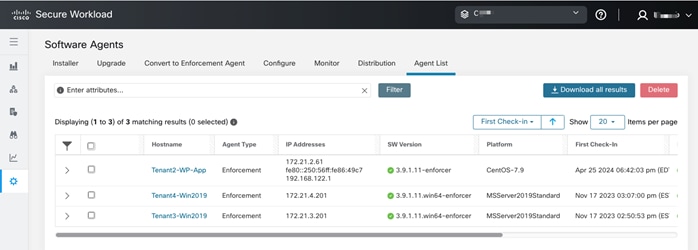
Step 3. To view details of a single agent, click the hostname. Detailed information about the host is shown below:
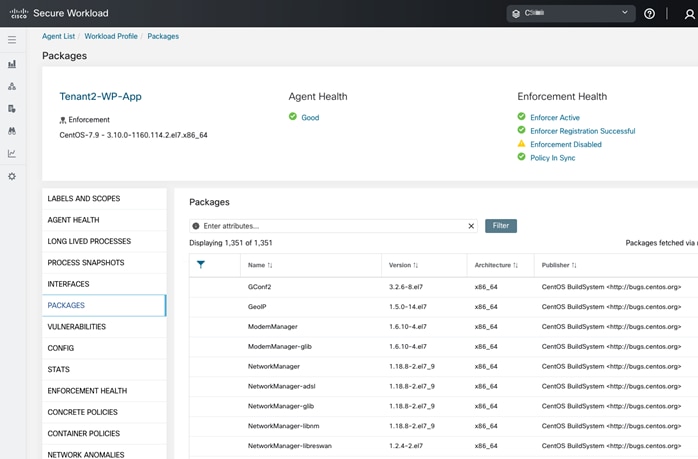
If there are vulnerabilities in a package, a warning sign will appear, as shown below:
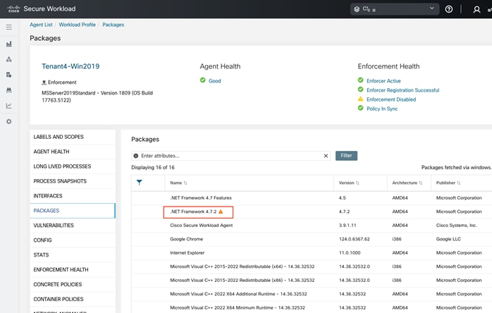
Step 4. Clicking the warning sign or Vulnerabilities will show the vulnerabilities and their status.
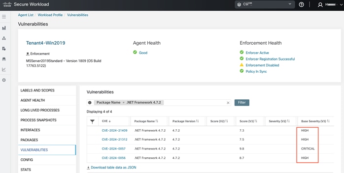
Procedure 5. Configuring Cisco Secure Workload Policies
Now that the Secure Workload agents are installed on the application VMs, configure the policies in the Secure Workload dashboard. To configure Secure Workload agents and settings, follow the Secure Workload documentation.
Deploy Storage (Adaptive) Quality of Service
This chapter contains the following:
● Explore the Impact of QoS and Adaptive QoS Configurations
Optionally, you can use storage quality of service (QoS) to guarantee that the performance of critical workloads is not degraded by competing workloads. For example, you can set a throughput ceiling on a competing workload to limit its impact on system resources, or set a throughput floor for a critical workload, ensuring that it meets minimum throughput targets, regardless of demand by competing workloads. You can even set a ceiling and floor for the same workload.
You can use an adaptive QoS policy group to automatically scale a throughput ceiling or floor to volume size changes, maintaining the ratio of IOPS to TBs|GBs as the size of the volume changes. That is a significant advantage when you are managing hundreds or thousands of workloads in a large deployment.
For a multi-tenant environment, the ONTAP storage QoS settings can be applied at the tenant SVM level, or at the individual object level such as volume or LUN. Table 8 lists the implications of assigning QoS at different levels.
Table 8. Implications of assigning QoS at different levels
| If you assign a... |
Then you cannot assign... |
| Vserver to a policy group |
Any storage objects contained by the Vserver to a policy group |
| Volume to a policy group |
The volume's containing Vserver or any child LUNs or files to a policy group |
| LUN to a policy group |
The LUN's containing volume or Vserver to a policy group |
| File to a policy group |
The file's containing volume or Vserver to a policy group |
Procedure 1. Create and apply QoS Policies
The following procedure creates QoS policies and applies them to the tenants at the SVM level for two tenants, Tenant1 and Tenant2, assuming the tenant SVMs are already created.
Step 1. Log into NetApp ONTAP system CLI.
Step 2. To create a QoS policy group and apply it to an SVM, volume, file, or LUN, use the following command syntax:
qos policy-group create -policy-group <tenant-qos-policy-group> -vserver <tenant-svm> -max-throughput <number_of_iops | MB/s | iops,MB/s> -min-throughput <number_of_iops | MB/s iops,MB/s> -is-shared <true | false>
storage_object modify -vserver <tenant-svm> -qos-policy-group <tenant-qos-policy-group>
AB03-A400::> qos policy-group create -policy-group tenant<X>-qos -vserver Tenant<X>-SVM -max-throughput <number_of_iops | MB/s | iops,MB/s> -min-throughput <number_of_iops | MB/s | iops,MB/s> (where X = 1,2,3 etc.)
AB03-A400::> vserver modify -vserver Tenant<X>-SVM -qos-policy-group tenant<X>-qos (where X = 1,2,3 etc.)
For example:
AB03-A400::> qos policy-group create -policy-group tenant1-qos -vserver Tenant1-SVM -max-throughput 10000iops,200MB/s -min-throughput 0
AB03-A400::> qos policy-group create -policy-group tenant2-qos -vserver Tenant2-SVM -max-throughput 10000iops,200MB/s -min-throughput 0
AB03-A400::> vserver modify -vserver Tenant1-SVM -qos-policy-group tenant1-qos
AB03-A400::> vserver modify -vserver Tenant2-SVM -qos-policy-group tenant2-qos
Note: You can specify the throughput limit for the ceiling in IOPS, MB/s, or IOPS, MB/s. If you specify both IOPS and MB/s as shown in the examples above, whichever limit is reached first is enforced. By default, the QoS policies are shared between the members. By setting the -is-shared option to false, the policies can be applied to each member individually.
Procedure 2. Remove QoS Policies
Step 1. You can remove the association of QoS policy group with the Vserver/SVM using the following syntax:
storage_object modify -vserver <tenant-svm> -qos-policy-group none
AB03-A400::> vserver modify -vserver Tenant<X>-SVM -qos-policy-group none (where X = 1,2,3 etc.)
For example:
AB03-A400::> vserver modify -vserver Tenant1-SVM -qos-policy-group none
AB03-A400::> vserver modify -vserver Tenant2-SVM -qos-policy-group none
Procedure 3. Create and apply adaptive QoS Policies
Use an adaptive QoS policy group to automatically scale a throughput ceiling or floor to volume size, maintaining the ratio of IOPS to TBs|GBs as the size of the volume changes.
Step 1. To create and apply adaptive QoS policy group, use the following command syntax (assuming that the tenant SVMs and NFS volumes are already created).
qos adaptive-policy-group create -policy group <adaptive-qos-policy-group> -vserver <tenant-svm> -expected-iops <number_of_iops/TB|GB> -peak-iops <number_of_iops/TB|GB> -expected-iops-allocation <allocated-space|used-space> -peak-iops-allocation <allocated-space|used-space> -absolute-min-iops <number_of_iops> -block-size <8K|16K|32K|64K|ANY>
volume modify -vserver <tenant-svm> -volume <tenant-NFS-volume> -qos-adaptive-policy-group <adaptive-qos-policy-group>
AB03-A400::> qos adaptive-policy-group modify -policy-group tenant<X>-qos-adaptive -expected-iops <number_of_iops/TB|GB> -peak-iops <number_of_iops/TB|GB> -peak-iops-allocation allocated-space -absolute-min-iops <number_of_iops> (where X = 1,2,3 etc.)
AB03-A400::> volume modify -vserver Tenant<X>-SVM -volume tenant<X>_nfs_1 -qos-adaptive-policy-group tenant<X>-qos-adaptive (where X = 1,2,3 etc.)
For example:
AB03-A400::> qos adaptive-policy-group modify -policy-group tenant1-qos-adaptive -expected-iops 5000/tb -peak-iops 10000iops/tb -peak-iops-allocation allocated-space -absolute-min-iops 1000iops
Notice: The QoS adaptive policy group changes could take up to 5 minutes to take effect.
AB03-A400::> volume modify -vserver Tenant1-SVM -volume tenant1_nfs_1 -qos-adaptive-policy-group tenant1-qos-adaptive
Explore the Impact of QoS and Adaptive QoS Configurations
CentOS VMs are created in the tenants and the exported NFS volumes are mounted in the VMs for I/O testing to explore the impacts of QoS and adaptive QoS configurations. The Vdbench tool installed in the VMs is used to generate disk I/O workload to explore some of the ONTAP quality of service (QoS) capabilities that can be utilized to allocate storage I/O resources to different tenants and workloads.
To visualize the impacts from QoS configurations, NAbox tool is deployed to examine the metrics collected by NetApp Harvest tool and the metrics are shown in Grafana dashboards (in NAbox). Refer to Vdbench, NAbox, and NetApp Harvest for their respective installation and usage information.
QoS Impact Demonstration
For each tenant Vdbench VM, a similar Vdbench configuration file is created to stress the NFS file system mapped in the VMs. These NFS volumes are exported to the VMs in the different tenants and named according to the tenant names, such as tenant1_nfs_1 for tenant1. Here is an example configuration for tenant1, which configures workload using 8k random I/O with 80% read. A total of 1000 files, each 50m in size, are generated by using depth of 1, width of 10, and files of 1000:
fsd=fsd1,anchor=/tenant1_nfs_1/vdbench,depth=1,width=10,files=100,size=50m
fwd=fwd1,fsd=fsd1,rdpct=80,xfersize=8k,fileselect=random,fileio=random,threads=8
rd=rd1,fwd=fwd*,fwdrate=max,format=yes,elapsed=900,interval=3
During the initial file creation process, Vdbench uses a transfer size of 128k (131,072). After the data files are created, the specified I/O workload is generated for the specified duration of testing.
A screenshot of the Vdbench I/O generating process is captured in the NAbox Grafana dashboard, as shown below, when QoS is not configured. The screenshot shows the top three volumes by total IOPs (left graph), average throughput (middle graph), and average latency (right graph) for the three tenant SVMs.
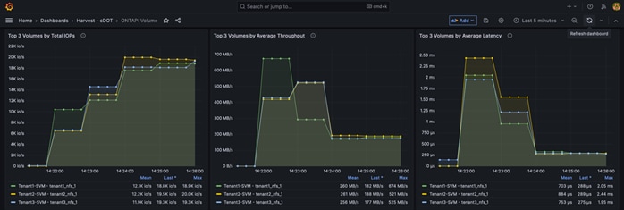
From this screenshot, you see tenant1, shown in green color, file creation process using about 10K IOPs (left graph) and generates around 670 MB/s data throughput (middle graph). At steady state, tenant1 I/O was running around 19K IOPs and 180MB/s.
To see how QoS policy can be used to limit IOPs and throughputs of tenants, the following QoS policies are created and applied to the three tenants to limit IOPs to 10,000 IOPs and throughputs to 200 MB/s:
AB03-A400::> qos policy-group create -policy-group tenant1-qos -vserver Tenant1-SVM -max-throughput 10000iops,200MB/s -min-throughput 0
AB03-A400::> qos policy-group create -policy-group tenant2-qos -vserver Tenant2-SVM -max-throughput 10000iops,200MB/s -min-throughput 0
AB03-A400::> qos policy-group create -policy-group tenant3-qos -vserver Tenant3-SVM -max-throughput 10000iops,200MB/s -min-throughput 0
AB03-A400::> vserver modify -vserver Tenant1-SVM -qos-policy-group tenant1-qos
AB03-A400::> vserver modify -vserver Tenant2-SVM -qos-policy-group tenant2-qos
AB03-A400::> vserver modify -vserver Tenant3-SVM -qos-policy-group tenant3-qos
Looking at the throughputs dashboard below (middle graph), you see that the write throughputs are limited to around 200 MB/s during the data creation phase due to the applied QoS policies. Since the transfer size for the initial data creation phase is 128k, the Vdbench IOPs are reduced accordingly due to the set throughput limit.
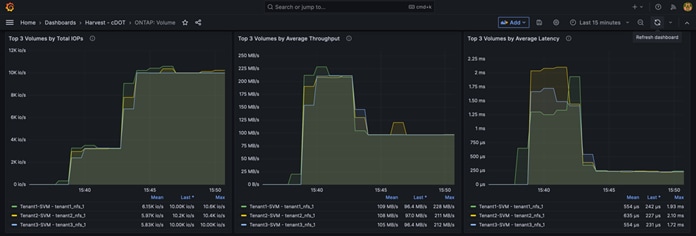
After the data files were created, the steady state I/Os (left graph) with a transfer size of 8k are limited to around 10,000 IOPs as defined in the QoS policies. The I/O throughput dropped accordingly due to the 8k transfer size. The applied QoS policy impacts both the throughputs of Vdbench data file creation and the IOPs in the steady state.
When the QoS requirements are different for the tenants, you can adjust the QoS policy group configurations individually for the tenants. For example, the following commands modify the QoS policy to three different IOPs, throughput combinations for the three tenants:
AB03-A400::> qos policy-group modify -policy-group tenant1-qos -max-throughput 10000IOPS,200MB/s
AB03-A400::> qos policy-group modify -policy-group tenant2-qos -max-throughput 20000IOPS,300MB/s
AB03-A400::> qos policy-group modify -policy-group tenant3-qos -max-throughput 30000IOPS,400MB/s
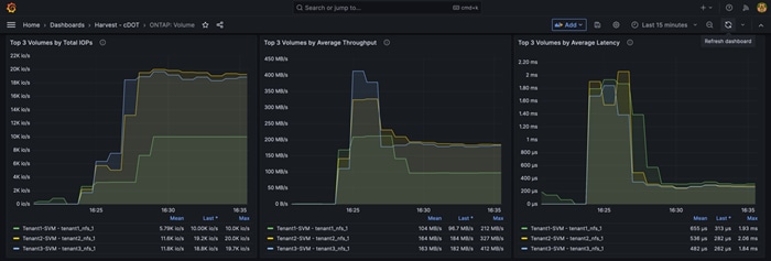
When the tenant throughputs are limited to 200, 300, and 400 MB/s respectively, Vdbench reached respective throughput limits during the file creation phase for the three tenants as shown in the middle graph in the screenshot above.
For the steady state workloads, the IOPs (left graph) above shows that tenant1 (green line) was limited to around 10,000 IOPs whereas tenant2 and tenant3 were able to get to around 20,000 IOPs. Even though tenant3 is given a higher IOPs limit of 30,000 IOPs, it is not able to take advantage of the higher IOPs limit with the given workload and VM configuration.
Adaptive QoS Impact Demonstration
To demonstrate the impacts of adaptive QoS policy, two 500G volumes are created and mapped in two Vdbench VMs residing in Tenant3. For VM1 and the NFS volume tenant3_nfs_1, we attach an adaptive QoS policy with the specifications shown below. For VM2 and its NFS volume tenant3_nfs_2, we do not specify an adaptive QoS policy.
AB03-A400::> qos adaptive-policy-group modify -policy-group tenant3-qos-adaptive -expected-iops 5000/tb -peak-iops 10000iops/tb -peak-iops-allocation allocated-space -absolute-min-iops 1000iops
Notice: The QoS adaptive policy group changes could take up to 5 minutes to take effect.
AB03-A400::> volume modify -vserver Tenant3-SVM -volume tenant3_nfs_1 -qos-adaptive-policy-group tenant3-qos-adaptive
Here is what the adaptive QoS configuration association looks like for the Tenant3 volumes:
AB03-A400::> volume show -vserver Tenant3-SVM -fields volume,size,qos-adaptive-policy-group
vserver volume size qos-adaptive-policy-group
----------- ---------------- ---- -------------------------
Tenant3-SVM Tenant3_SVM_root 1GB -
Tenant3-SVM tenant3_nfs_1 500GB
tenant3-qos-adaptive
Tenant3-SVM tenant3_nfs_2 500GB
-
3 entries were displayed.
We run Vdbench I/O using similar specifications as before and use the Grafana dashboards to compare the I/O performance differences between the two NFS volumes: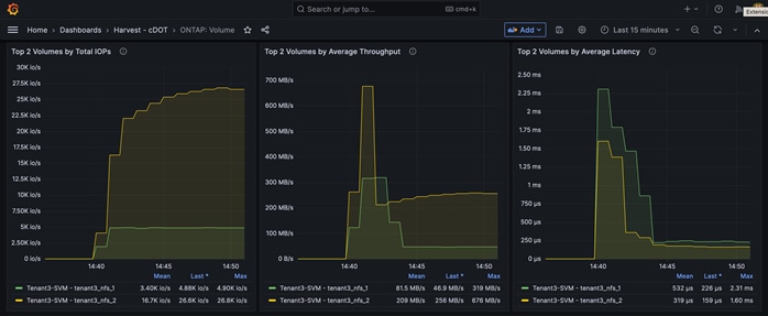
The IOPs dashboard above shows that the tenant3_nfs_1 volume IOPs (green line in the left graph) is being limited to about 5000 IOPs because of the applied QoS policy (max 10,000 IOPs/tb x 0.5 tb = 5000 IOPs). However, tenant3_nfs_2 volume IOPs reached around 27K IOPs without adaptive QoS policy applied.
Increasing the size of the tenant3_nfs_1 volume from 500GB to 1TB, the adaptive QoS policy will allow the specified IOPs limit to increase accordingly:
AB03-A400::> vol size -vserver Tenant3-SVM -volume tenant3_nfs_1 -new-size 1tb
vol size: Volume "Tenant3-SVM:tenant3_nfs_1" size set to 1t.
Here is what the updated adaptive QoS configuration association looks like for the Tenant3 volumes:
AB03-A400::> volume show -vserver Tenant3-SVM -fields volume,size,qos-adaptive-policy-group
vserver volume size qos-adaptive-policy-group
----------- ---------------- ---- -------------------------
Tenant3-SVM Tenant3_SVM_root 1GB -
Tenant3-SVM tenant3_nfs_1 1TB tenant3-qos-adaptive
Tenant3-SVM tenant3_nfs_2 500GB
-
3 entries were displayed.
As the IOPs dashboard (left graph) shows below, the tenant3_nfs_1 volume IOPs (green line) increased to around 10,000 IOPs based on the updated volume allocation size (max 10,000 IOPs/tb x 1.0 tb = 10,000 IOPs) without changing the adaptive QoS configurations.
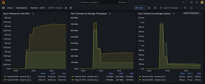
Ransomware Protection and Recovery
This chapter contains the following:
● Use ONTAP Fpolicy to Protect Ransomware with Known File Extensions
Ransomware attacks continue to be a big threat to enterprises as attacks can lead to business disruptions, monetary and data losses, and business reputation impact. NetApp provides a suite of tools and solutions that can be utilized to help detect and recover from ransomware attacks quickly to minimize business impacts.
The ONTAP FPolicy framework is used to monitor and manage file access. ONTAP volume Snapshot is a point-in-time copy of the volume data for quick recovery. Autonomous ransomware protection (ARP) automates the detection and provides protection and alerts for ransomware attacks. Additional external tools such as NetApp Cloud Insights can help make the orchestration and protection against ransomware simple.
ARP is designed to protect against denial-of-service attacks where the attacker withholds data until a ransom is paid. ARP offers anti-ransomware detection based on:
● Identification of the incoming data as encrypted or plaintext.
● Analytics, which detects following:
◦ Entropy: an evaluation of the randomness of data in a file.
◦ File extension types: an extension that does not conform to the normal extension type.
◦ File IOPS: a surge in abnormal volume activity with data encryption.
ARP can detect the spread of most ransomware attacks after only a small number of files are encrypted, act automatically to protect data, and alert you that a suspected attack is happening.
When ARP runs in learning mode, it develops an alert profile based on the analytic areas: entropy, file extension types, and file IOPS. After running ARP in learning mode for enough time to assess workload characteristics, you can switch to active mode and start protecting your data. Once ARP has switched to active mode, ONTAP will create ARP Snapshot to protect the data if a threat is detected.
Note: To avoid false positives, it is recommended that you leave ARP in learning mode for a long enough period so ARP can gather sufficient data to develop analytics for detecting a thread. Beginning with ONTAP 9.13.1, ARP automatically determines the optimal learning period interval and automates the switch. You can disable this setting on the associated SVM if you want to manually control the switching from learning mode to active mode.
Procedure 1. Enable autonomous ransomware protection in ONTAP System Manager
To enable Anti-ransomware protection for volumes in ONTAP System Manager, use the following steps.
Step 1. Log into NetApp ONTAP System Manager GUI.
Step 2. Select Storage > Volumes.
Step 3. Click the name of the volume you wish to protect to see information about the volume.
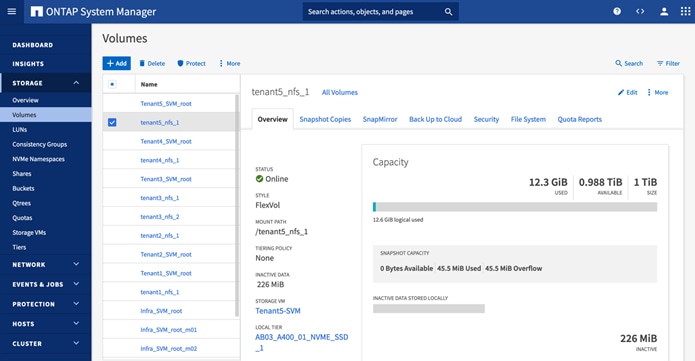
Step 4. Click the Security tab for the selected volume.
Step 5. Set the Anti-ransomware STATUS to Enabled in learning mode.
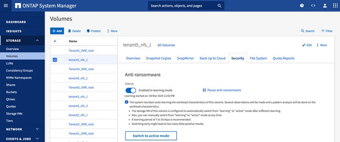
Step 6. When the learning period is over, click Switch to active mode to activate ARP.
Step 7. To display ARP status for all volumes in the Volumes pane, select Show/Hide, then ensure that Anti-ransomware status is checked.
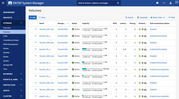
Procedure 2. (Optional) Check the default ARP attack detection parameters
To see the default attack detection parameter configurations in ONTAP for a particular volume, perform the following steps.
Step 1. Log into ONTAP system CLI.
Step 2. Show the attack detection parameter using the following ONTAP command line syntax.
security anti-ransomware volume attack-detection-parameters show -vserver <svm-name> -volume <volume-name>
AB03-A400::> security anti-ransomware volume attack-detection-parameters show -vserver Tenant<X>-SVM -volume tenant<x>_nfs_1 (where X = 1,2,3 etc.)
For example:
AB03-A400::> security anti-ransomware volume attack-detection-parameters show -vserver Tenant5-SVM -volume tenant5_nfs_1
Vserver Name : Tenant5-SVM
Volume Name : tenant5_nfs_1
Is Detection Based on High Entropy Data Rate? : true
Is Detection Based on Never Seen before File Extension? : true
Is Detection Based on File Create Rate? : true
Is Detection Based on File Rename Rate? : true
Is Detection Based on File Delete Rate? : true
Is Detection Relaxing Popular File Extensions? : true
High Entropy Data Surge Notify Percentage : 100
File Create Rate Surge Notify Percentage : 100
File Rename Rate Surge Notify Percentage : 100
File Delete Rate Surge Notify Percentage : 100
Never Seen before File Extensions Count Notify Threshold : 20
Never Seen before File Extensions Duration in Hour : 24
Note: You can customize the attack detection parameters using the "security anti-ransomware volume attack-detection-parameters modify" command. Tailoring the attack detection parameters based on volume specific workload characteristics can help improve the accuracy of the detection. Once a threat is suspected, a proactive volume Snapshot is created with Anti_ransomware_backup tag in the Snapshot name.
Procedure 3. Autonomous ransomware protection validation
To illustrate the working of autonomous ransomware protection, use the following high-level steps, and refer to the previously covered information for additional details.
Step 1. Enable anti-ransomware protection in learning mode for a test NFS volume.
Step 2. Export the test NFS volume.
Step 3. Mount the exported NFS volume in a test Linux VM.
Step 4. Create test data set in the test volume.
Note: For this example, data from a Linux installation DVD was copied over to the NFS volume.
Step 5. Wait sufficient time for ARP to gather initial learning statistics before switching ARP to active mode. See ONTAP System Manager screenshot below for analytics from the initial learning of the test volume tenant5_nfs_1, including percentage of high entropy data, maximum rate of file operations, and the number observed file types.
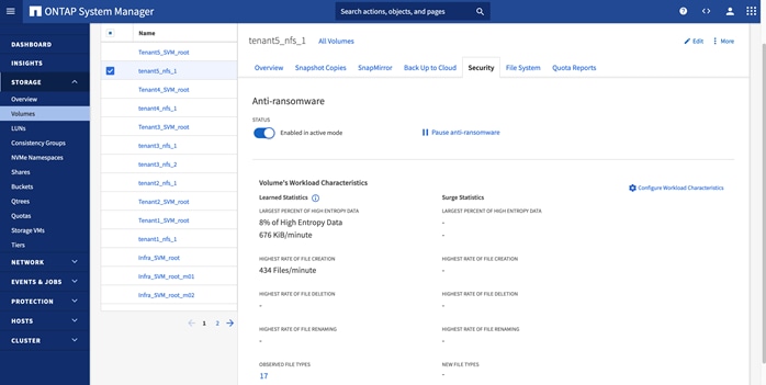
Step 6. Perform a simulated ransomware attack. To simulate a ransomware attack, a shell script is executed in the test Linux VM to encrypt the files found in the test NFS volume by using the gpg encryption tool. The encrypted files are saved with an additional file extension “.lckd” appended to the original filename and the original files are deleted. The following shows partial output from the execution of a test script to simulate a ransomware attack.
[admin@Tenant5-vdbench ARP]$ ./encrypt_gpg.sh
encrypt each file
gpg --encrypt --recipient admin@secsoln.local --output /tenant5_nfs_1/ARP/AppStream/repodata/0ec907e2460ea55f3a652fcd30e9e73333ebbd206d1f940d7893304d6789f10f-comps-AppStream.x86_64.xml.lckd /tenant5_nfs_1/ARP/AppStream/repodata/0ec907e2460ea55f3a652fcd30e9e73333ebbd206d1f940d7893304d6789f10f-comps-AppStream.x86_64.xml
gpg --encrypt --recipient admin@secsoln.local --output /tenant5_nfs_1/ARP/AppStream/repodata/7726f887bd9877a3c62aef66861c0194490b13f5bd729524465b6c4547143397-comps-AppStream.x86_64.xml.gz.lckd /tenant5_nfs_1/ARP/AppStream/repodata/7726f887bd9877a3c62aef66861c0194490b13f5bd729524465b6c4547143397-comps-AppStream.x86_64.xml.gz
gpg --encrypt --recipient admin@secsoln.local --output /tenant5_nfs_1/ARP/AppStream/repodata/TRANS.TBL.lckd /tenant5_nfs_1/ARP/AppStream/repodata/TRANS.TBL
gpg --encrypt --recipient admin@secsoln.local --output /tenant5_nfs_1/ARP/AppStream/repodata/a5b844507f918c76709bada7be26ca3d3d455e3a3e2443291cf602f22834fbbc-primary.xml.gz.lckd /tenant5_nfs_1/ARP/AppStream/repodata/a5b844507f918c76709bada7be26ca3d3d455e3a3e2443291cf602f22834fbbc-primary.xml.gz
gpg --encrypt --recipient admin@secsoln.local --output /tenant5_nfs_1/ARP/AppStream/repodata/c64cdd8dc648f18e2a08e7f557a751d2acb1769741148fb6fc19ac486e8db732-modules.yaml.gz.lckd /tenant5_nfs_1/ARP/AppStream/repodata/c64cdd8dc648f18e2a08e7f557a751d2acb1769741148fb6fc19ac486e8db732-modules.yaml.gz
gpg --encrypt --recipient admin@secsoln.local --output /tenant5_nfs_1/ARP/AppStream/repodata/cc651b9ea4a688b1fff209968698640d2116082eb5f413aaf8e560f90411ba77-other.xml.gz.lckd /tenant5_nfs_1/ARP/AppStream/repodata/cc651b9ea4a688b1fff209968698640d2116082eb5f413aaf8e560f90411ba77-other.xml.gz
<SNIP>
Step 7. A Snapshot is automatically created by ARP when a ransomware attack is suspected.
The Snapshot Copies tab in the ONTAP System Manager screenshot below shows an ARP created Snapshot with Anti_ransomware_backup in the Snapshot name alongside several hourly Snapshots.
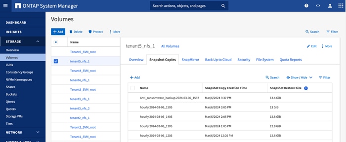
The Snapshot copies for a NFS volume are available from the “.snapshot” directory as shown below in the VM’s NFS volume directory structure.
[admin@Tenant5-vdbench /]$ ls -l /tenant5_nfs_1/.snapshot
total 32
drwxr-xr-x. 5 root root 4096 Mar 6 14:30 Anti_ransomware_backup.2024-03-06_1537
drwxr-xr-x. 5 root root 4096 Mar 5 17:11 daily.2024-03-06_0010
drwxr-xr-x. 5 root root 4096 Mar 5 17:11 hourly.2024-03-06_1005
drwxr-xr-x. 5 root root 4096 Mar 5 17:11 hourly.2024-03-06_1105
drwxr-xr-x. 5 root root 4096 Mar 5 17:11 hourly.2024-03-06_1205
drwxr-xr-x. 5 root root 4096 Mar 5 17:11 hourly.2024-03-06_1305
drwxr-xr-x. 5 root root 4096 Mar 5 17:11 hourly.2024-03-06_1405
drwxr-xr-x. 5 root root 4096 Mar 6 14:30 hourly.2024-03-06_1505
Step 8. Evaluate files in the volume to determine the extent of the ransomware attack.
For example, when we examine the content of the media.repo.lckd file in the directory, we can see that its content is impacted, as the original file should be a readable text file.
[admin@Tenant5-vdbench ARP]$ ls -l /tenant5_nfs_1/ARP
total 52
drwxr-xr-x. 4 admin admin 4096 Mar 6 14:50 AppStream
drwxr-xr-x. 4 admin admin 4096 Mar 6 14:51 BaseOS
drwxr-xr-x. 3 admin admin 4096 Mar 6 14:51 EFI
-rw-rw-r--. 1 admin admin 530 Mar 6 15:42 EULA.lckd
-rw-rw-r--. 1 admin admin 683 Mar 6 15:42 extra_files.json.lckd
-rw-rw-r--. 1 admin admin 7161 Mar 6 15:42 GPL.lckd
drwxr-xr-x. 3 admin admin 4096 Mar 6 16:29 images
drwxr-xr-x. 2 admin admin 4096 Mar 6 16:29 isolinux
-rw-rw-r--. 1 admin admin 7162 Mar 6 15:43 LICENSE.lckd
-rw-rw-r--. 1 admin admin 423 Mar 6 15:43 media.repo.lckd
-rw-rw-r--. 1 admin admin 462 Mar 6 15:43 TRANS.TBL.lckd
[admin@Tenant5-vdbench ARP]$ cat /tenant5_nfs_1/ARP/media.repo.lckd
?
?|d??nF7 >?V?:?3E??w?>???3/wB??z??9F*?#"?
Ђe_??z????H??\Y#????I
7??A???"z??> ??
|$9??t???n????$J1?)????<^????ެ@9[???{P??!???4?#?9: ??]аx?"yĽ??t??6?o?{
?1N???dF ?dV??'`?̮?!?h>мce}?c{??M7???x??k??Y+?????C
?p???ف;??????ф?K??Җ+?:IX??Ѥ??d??????2?,?&??
??|?Y?tZ????vѼ??ul|??U?k?P?[@??8A??? ?C>?????H?.TR6??w?e?R?i?????d????????7)%????=WO?f5?S wڙݲ??,*3?E
[admin@Tenant5-vdbench ARP]
Step 9. Evaluate files in the automatic ARP Snapshot to determine the extent of the ransomware attack before the automatic ARP Snapshot is taken.
Step 10. To determine how many files in the automatic ARP Snapshot are impacted for this attack, you can search for the “lckd” file extension in the Anti_ransomware_backup Snapshot with the help of find and wc tools. In this case, it finds 473 files which are affected before the ARP Snapshot is taken.
[admin@Tenant5-vdbench ~]$ find /tenant5_nfs_1/.snapshot/Anti_ransomware_backup.2024-03-06_1537/ARP -type f | grep lckd | wc
473 473 63470
Step 11. Restore files affected by ransomware attack by copying them from the latest scheduled Snapshot taken before the attack.
Note: Depending on the configured Snapshot schedule, a file affected by the ransomware attack might already exist when the most recent scheduled Snapshot was taken. In such cases, restore the file from one of the other available Snapshots. For example, examine the media.repo file in the hourly Snapshot hourly.2024-03-06_1505 reveals that it is not affected / encrypted in that Snapshot.
[admin@Tenant5-vdbench ARP]$ ls -l /tenant5_nfs_1/.snapshot/hourly.2024-03-06_1505/ARP
total 76
dr-xr-xr-x. 4 admin admin 4096 Mar 6 14:50 AppStream
dr-xr-xr-x. 4 admin admin 4096 Mar 6 14:51 BaseOS
dr-xr-xr-x. 3 admin admin 4096 Mar 6 14:51 EFI
-r-xr-xr-x. 1 admin admin 298 Mar 6 14:51 EULA
-r-xr-xr-x. 1 admin admin 741 Mar 6 14:51 extra_files.json
-r-xr-xr-x. 1 admin admin 18092 Mar 6 14:51 GPL
dr-xr-xr-x. 3 admin admin 4096 Mar 6 14:51 images
dr-xr-xr-x. 2 admin admin 4096 Mar 6 14:51 isolinux
-r-xr-xr-x. 1 admin admin 18092 Mar 6 14:51 LICENSE
-r-xr-xr-x. 1 admin admin 88 Mar 6 14:51 media.repo
-r-xr-xr-x. 1 admin admin 1542 Mar 6 14:51 TRANS.TBL
[admin@Tenant5-vdbench ARP]$ cat /tenant5_nfs_1/.snapshot/hourly.2024-03-06_1505/ARP/media.repo
[InstallMedia]
name=CentOS Stream 8
mediaid=None
metadata_expire=-1
gpgcheck=0
cost=500
Step 12. As a result, you can copy that file from the hourly Snapshot before the Ransomware attack and delete the encrypted copy to restore the original file.
[admin@Tenant5-vdbench ARP]$ cp /tenant5_nfs_1/.snapshot/hourly.2024-03-06_1505/ARP/media.repo /tenant5_nfs_1/ARP/media.repo
[admin@Tenant5-vdbench ARP]$ rm /tenant5_nfs_1/ARP/media.repo.lckd
[admin@Tenant5-vdbench ARP]$ ls -l /tenant5_nfs_1/ARP
total 52
drwxr-xr-x. 4 admin admin 4096 Mar 6 14:50 AppStream
drwxr-xr-x. 4 admin admin 4096 Mar 6 14:51 BaseOS
drwxr-xr-x. 3 admin admin 4096 Mar 6 14:51 EFI
-rw-rw-r--. 1 admin admin 530 Mar 6 15:42 EULA.lckd
-rw-rw-r--. 1 admin admin 683 Mar 6 15:42 extra_files.json.lckd
-rw-rw-r--. 1 admin admin 7161 Mar 6 15:42 GPL.lckd
drwxr-xr-x. 3 admin admin 4096 Mar 6 16:29 images
drwxr-xr-x. 2 admin admin 4096 Mar 6 16:29 isolinux
-rw-rw-r--. 1 admin admin 7162 Mar 6 15:43 LICENSE.lckd
-r-xr-xr-x. 1 admin admin 88 Mar 6 16:36 media.repo
-rw-rw-r--. 1 admin admin 462 Mar 6 15:43 TRANS.TBL.lckd
[admin@Tenant5-vdbench ARP]$ cat /tenant5_nfs_1/ARP/media.repo
[InstallMedia]
name=CentOS Stream 8
mediaid=None
metadata_expire=-1
gpgcheck=0
cost=500
Note: When many files are affected before the automatic ARP Snapshot is taken, you might want to automate the restore process by running a script to find the impacted files and attempt to replace them from a known good Snapshot if they can be found there.
Step 13. Optional - restore volume from a Snapshot. You can restore a volume from a volume Snapshot when a lot of files are impacted by the ransomware attack to help speed up the recovery. To restore the contents of a volume from a Snapshot copy with ONTAP CLI, use the following syntax.
volume snapshot restore -vserver <tenant-svm> -volume <affected-volume> -snapshot <most-recent-known-good-snapshot>
For example, you can restore the volume from the automatic ARP Snapshot, Anti_ransomware_backup.2024-03-06_1537, which is taken shortly after the ransomware attack.
AB03-A400::> volume snapshot restore -vserver Tenant5-SVM -volume tenant5_nfs_1 -snapshot Anti_ransomware_backup.2024-03-06_1537
Note: If there has not been much change since the last known good scheduled Snapshot copy, you can also choose to replace the affected volume completely from the last known good Snapshot copy before the ransomware attack.
For example, the following shows an attempt to restore the volume from an hourly Snapshot, hourly.2024-03-06_1505, which was taken before the ransomware attack:
AB03-A400::> volume snapshot restore -vserver Tenant5-SVM -volume tenant5_nfs_1 -snapshot hourly.2024-03-06_1505
Error: command failed: Failed to promote Snapshot copy "hourly.2024-03-06_1505" because one or more newer Snapshot copies are
currently used as a reference Snapshot copy for data protection operations: Anti_ransomware_backup.2024-03-06_1537.
The operation failed because there is a more recent Snapshot, such as the Anti_ransomware_backup Snapshot that is used as a reference Snapshot copy for data protection operation.
Note: If you have determined that there is indeed not much change since the last known good Snapshot and you are willing to replace the volume data with the last known good Snapshot copy, use the force option and replace the volume entirely as shown below:
AB03-A400::> volume snapshot restore -vserver Tenant5-SVM -volume tenant5_nfs_1 -snapshot hourly.2024-03-06_1505 -force
Warning: Snapshot copy "hourly.2024-03-06_1505" is not the most recent copy. Promoting this Snapshot copy will delete all copies made after it.
Do you want to continue? {y|n}: y
Warning: Quota rules currently enforced on volume "tenant5_nfs_1" might change during this operation. If the currently enforced quota rules are different from those in Snapshot copy "hourly.2024-03-06_1505", you might have to resize or reinitialize quotas on this volume after this operation.
Do you want to continue? {y|n}: y
Warning: Export policies currently enforced on the qtrees of volume "tenant5_nfs_1" will not change during this operation. If the currently enforced export policies are different from those in Snapshot copy "hourly.2024-03-06_1505", reassign the export policies of the qtrees on this volume after this operation.
Do you want to continue? {y|n}: y
Note: When the force option is used and the Snapshot selected for the restore command is not the most recent copy, all other Snapshot copies made after that will be deleted. As a result, you will need to confirm the operation to promote the selected Snapshot as the current content for the volume.
When checking on the client after restoring the volume content from a known good Snapshot, there are no Ransomware encrypted files with the “lckd” file extension.
[admin@Tenant5-vdbench ARP]$ ls -l /tenant5_nfs_1/ARP
total 76
dr-xr-xr-x. 4 admin admin 4096 Mar 6 14:50 AppStream
dr-xr-xr-x. 4 admin admin 4096 Mar 6 14:51 BaseOS
dr-xr-xr-x. 3 admin admin 4096 Mar 6 14:51 EFI
-r-xr-xr-x. 1 admin admin 298 Mar 6 14:51 EULA
-r-xr-xr-x. 1 admin admin 741 Mar 6 14:51 extra_files.json
-r-xr-xr-x. 1 admin admin 18092 Mar 6 14:51 GPL
dr-xr-xr-x. 3 admin admin 4096 Mar 6 14:51 images
dr-xr-xr-x. 2 admin admin 4096 Mar 6 14:51 isolinux
-r-xr-xr-x. 1 admin admin 18092 Mar 6 14:51 LICENSE
-r-xr-xr-x. 1 admin admin 88 Mar 6 14:51 media.repo
-r-xr-xr-x. 1 admin admin 1542 Mar 6 14:51 TRANS.TBL
[admin@Tenant5-vdbench ARP]$ find /tenant5_nfs_1/ARP -type f | grep lckd | wc
0 0 0
Use ONTAP Fpolicy to Protect Ransomware with Known File Extensions
FPolicy is a file access notification framework that is used to monitor and manage file access events on storage virtual machines (SVMs). There are two basic FPolicy configuration types. One configuration uses external FPolicy servers to process and act upon notifications. The other configuration does not use external FPolicy servers; instead, it uses the ONTAP internal, native FPolicy server for simple file blocking based on extensions.
For external FPolicy server configuration, the notification is sent to the FPolicy server, which screens the request and applies rules to determine whether the node should allow the requested file operation. For native FPolicy server configuration, the notification is screened internally. The request is allowed or denied based on file extension settings configured in the FPolicy scope.
FPolicy sends notifications to external FPolicy servers using the FPolicy interface. The notifications are sent either in synchronous or asynchronous mode. The notification mode determines what ONTAP does after sending notifications to FPolicy servers.
With asynchronous notifications, the node does not wait for a response from the FPolicy server, which enhances overall throughput of the system. This type of notification is suitable for applications where the FPolicy server does not require that any action be taken because of notification evaluation. For example, asynchronous notifications are used when the storage virtual machine (SVM) administrator wants to monitor and audit file access activity.
When configured to run in synchronous mode, the FPolicy server must acknowledge every notification before the client operation is allowed to continue. This type of notification is used when an action is required based on the results of notification evaluation. For example, synchronous notifications are used when the SVM administrator wants to either allow or deny requests based on criteria specified on the external FPolicy server.
Procedure 1. Configure a native Fpolicy to block known file extensions
Perform the following steps to configure a native Fpolicy to block known ransomware file extensions.
Step 1. Configure fpolicy event using the following command syntax.
vserver fpolicy policy event create -vserver <tenant-svm> -event-name <fpolicy-event-name> -protocol <protocol> -file-operations <list-of-file-operations>
AB03-A400::> vserver fpolicy policy event create -vserver Tenant<X>-SVM -event-name <fpolicy-event-name> -protocol <protocol> -file-operations <list-of-file-operations> (where X = 1,2,3 etc.)
For example:
AB03-A400::> vserver fpolicy policy event create -vserver Tenant5-SVM -event-name fpolicy-nfsv3 -protocol nfsv3 -file-operations create,write,rename
AB03-A400::> vserver fpolicy policy event create -vserver Tenant5-SVM -event-name fpolicy-nfsv4 -protocol nfsv4 -file-operations create,write,rename
AB03-A400::> vserver fpolicy policy event show -vserver Tenant5-SVM
Event File Is Volume
Vserver Name Protocols Operations Filters Operation
--------- ------------------ --------- ------------- ------------ ------------
Tenant5-SVM
fpolicy-nfsv3 nfsv3 create, - false
write, rename
Tenant5-SVM
fpolicy-nfsv4 nfsv4 create, - false
write, rename
2 entries were displayed.
Step 2. Create and show fpolicy using the following command syntax.
vserver fpolicy policy create -vserver <tenant-svm> -policy-name <name-of-policy> -events <name-of-policy-events> -engine native -is-mandatory true -allow-privileged-access no -is-passthrough-read-enabled false
vserver fpolicy policy show
AB03-A400::> vserver fpolicy policy create -vserver Tenant<X>-SVM -policy-name blockext -events fpolicy-nfsv3,fpolicy-nfsv4 -engine native -is-mandatory true -allow-privileged-access no -is-passthrough-read-enabled false (where X = 1,2,3 etc.)
For example:
AB03-A400::> vserver fpolicy policy create -vserver Tenant5-SVM -policy-name blockext -events fpolicy-nfsv3,fpolicy-nfsv4 -engine native -is-mandatory true -allow-privileged-access no -is-passthrough-read-enabled false
AB03-A400::> vserver fpolicy policy show
Vserver Policy Events Engine Is Mandatory Privileged
Name Access
-------------- ----------- ---------- ------------- ------------ -----------
Tenant5-SVM blockext fpolicy- native true no
nfsv3,
fpolicy-
nfsv4
Step 3. Configure, modify, and show fpolicy scope using the following syntax.
vserver fpolicy policy scope create -vserver <tenant-svm> -policy-name <name-of-policy> -file-extensions-to-include <name-of-file-extensions> -volumes-to-include *
vserver fpolicy policy scope modify -vserver <tenant-svm> -policy-name <name-of-policy> -file-extensions-to-include <name-of-file-extensions> -volumes-to-include *
vserver fpolicy policy scope show -vserver <tenant-svm> -instance
AB03-A400::> vserver fpolicy policy scope create -vserver Tenant<X>-SVM -policy-name blockext -file-extensions-to-include <name-of-file-extenstions> -volumes-to-include * (where X = 1,2,3 etc.)
AB03-A400::> vserver fpolicy policy scope modify -vserver Tenant<X>-SVM -policy-name blockext -file-extensions-to-include <name-of-updated-file-extenstions> -volumes-to-include * (where X = 1,2,3 etc.)
AB03-A400::> vserver fpolicy policy scope show -vserver Tenant<X>-SVM -instance (where X = 1,2,3 etc.)
For example:
AB03-A400::> vserver fpolicy policy scope create -vserver Tenant5-SVM -policy-name blockext -file-extensions-to-include mp3,mp4,locked -volumes-to-include *
AB03-A400::> vserver fpolicy policy scope show -vserver Tenant5-SVM -instance
Vserver: Tenant5-SVM
Policy: blockext
Shares to Include: -
Shares to Exclude: -
Volumes to Include: *
Volumes to Exclude: -
Export Policies to Include: -
Export Policies to Exclude: -
File Extensions to Include: mp3, mp4, locked
File Extensions to Exclude: -
AB03-A400::> vserver fpolicy policy scope modify -vserver Tenant5-SVM -policy-name blockext -file-extensions-to-include mp3,mp4,locked,lckd -volumes-to-include *
To see the fpolicy scope:
AB03-A400::> vserver fpolicy policy scope show -vserver Tenant5-SVM -instance
Vserver: Tenant5-SVM
Policy: blockext
Shares to Include: -
Shares to Exclude: -
Volumes to Include: *
Volumes to Exclude: -
Export Policies to Include: -
Export Policies to Exclude: -
File Extensions to Include: mp3, mp4, locked, lckd
File Extensions to Exclude: -
Step 4. Enable and show fpolicy using the following syntax.
vserver fpolicy enable -vserver <tenant-svm> -policy-name <name-of-policy> -sequence-number 1
vserver fpolicy show -vserver <tenant-svm>
AB03-A400::> vserver fpolicy enable -vserver Tenant<X>-SVM -policy-name blockext -sequence-number 1 (where X = 1,2,3 etc.)
AB03-A400::> vserver fpolicy show -vserver Tenant<X>-SVM(where X = 1,2,3 etc.) (where X = 1,2,3 etc.)
For example:
AB03-A400::> vserver fpolicy enable -vserver Tenant5-SVM -policy-name blockext -sequence-number 1
AB03-A400::> vserver fpolicy show -vserver Tenant5-SVM
Sequence
Vserver Policy Name Number Status Engine
------------- ----------------------- -------- -------- ---------
Tenant5-SVM blockext 1 on native
Step 5. Create encrypted files with blocked file extension.
After FPolicy is configured and enabled, we can attempt to encrypt and create files with “lckd” file extension from a NFS client. See below for a partial output which encrypts files in the directory.
[admin@Tenant5-vdbench ARP]$ ./encrypt_gpg.sh
encrypt each file
gpg --encrypt --recipient admin@secsoln.local --output /tenant5_nfs_1/ARP/AppStream/repodata/0ec907e2460ea55f3a652fcd30e9e73333ebbd206d1f940d7893304d6789f10f-comps-AppStream.x86_64.xml.lckd /tenant5_nfs_1/ARP/AppStream/repodata/0ec907e2460ea55f3a652fcd30e9e73333ebbd206d1f940d7893304d6789f10f-comps-AppStream.x86_64.xml
gpg: can't create '/tenant5_nfs_1/ARP/AppStream/repodata/0ec907e2460ea55f3a652fcd30e9e73333ebbd206d1f940d7893304d6789f10f-comps-AppStream.x86_64.xml.lckd': Permission denied
gpg: /tenant5_nfs_1/ARP/AppStream/repodata/0ec907e2460ea55f3a652fcd30e9e73333ebbd206d1f940d7893304d6789f10f-comps-AppStream.x86_64.xml: encryption failed: Permission denied
gpg --encrypt --recipient admin@secsoln.local --output /tenant5_nfs_1/ARP/AppStream/repodata/7726f887bd9877a3c62aef66861c0194490b13f5bd729524465b6c4547143397-comps-AppStream.x86_64.xml.gz.lckd /tenant5_nfs_1/ARP/AppStream/repodata/7726f887bd9877a3c62aef66861c0194490b13f5bd729524465b6c4547143397-comps-AppStream.x86_64.xml.gz
gpg: can't create '/tenant5_nfs_1/ARP/AppStream/repodata/7726f887bd9877a3c62aef66861c0194490b13f5bd729524465b6c4547143397-comps-AppStream.x86_64.xml.gz.lckd': Permission denied
gpg: /tenant5_nfs_1/ARP/AppStream/repodata/7726f887bd9877a3c62aef66861c0194490b13f5bd729524465b6c4547143397-comps-AppStream.x86_64.xml.gz: encryption failed: Permission denied
gpg --encrypt --recipient admin@secsoln.local --output /tenant5_nfs_1/ARP/AppStream/repodata/TRANS.TBL.lckd /tenant5_nfs_1/ARP/AppStream/repodata/TRANS.TBL
gpg: can't create '/tenant5_nfs_1/ARP/AppStream/repodata/TRANS.TBL.lckd': Permission denied
gpg: /tenant5_nfs_1/ARP/AppStream/repodata/TRANS.TBL: encryption failed: Permission denied
Due to the native Fpolicy configuration, creation of files with the “lckd” file extension is not allowed. Instead, the operations received permission denied error from the NFS server. This approach can be implemented to block the known ransomware file extensions along with autonomous ransomware protection to increase effectiveness. Please see Ransomware File Extensions List for a compiled list of known ransomware file extensions.
For information on utilizing Workload Security, which is a security feature of NetApp Cloud Insight for activity monitoring and potential attack detection and mitigation, and using NetApp SnapCenter plug-in for VM and application consistent backup and recovery, please see TR-4961: FlexPod ransomware protection & recovery with NetApp Cloud Insights and SnapCenter.
About the Authors
Haseeb Niazi, Principal Technical Marketing Engineer, Cisco Systems, Inc.
With more than two decades of experience at Cisco, Haseeb has built extensive expertise in Datacenter, Enterprise, and Service Provider Solutions and Technologies. As part of various solution teams and Advanced Services, he has guided numerous enterprise and service provider clients in the evaluation and deployment of a broad range of Cisco solutions. In his current role as a Principal Technical Marketing Engineer at the Cisco UCS business entity, Haseeb concentrates on multiple facets of various compute stacks, including networking, compute, virtualization, storage, and orchestration. Haseeb holds a master’s degree in computer engineering from the University of Southern California and is a Cisco Certified Internetwork Expert (CCIE 7848).
Jyh-shing Chen, Senior Technical Marketing Engineer, Hybrid Cloud Infra & OEM Solutions, NetApp Inc.
Jyh-shing Chen is a Senior Technical Marketing engineer at NetApp. His current focus is on FlexPod Converged Infrastructure solution enablement, validation, deployment and management simplification, and solution integration with Cisco Intersight. Jyh-shing joined NetApp in 2006 and had worked on storage interoperability and integration projects with Solaris and VMware vSphere operating systems, and qualifications of ONTAP MetroCluster solutions and Cloud Volumes data services. Before joining NetApp, Jyh-shing’s engineering experiences include software and firmware development on cardiology health imaging system, mass spectrometer system, Fibre Channel virtual tape library, and the research and development of microfluidic devices. Jyh-shing earned his BS and MS degrees from National Taiwan University, MBA degree from Meredith College, and PhD degree from MIT.
Acknowledgements
For their support and contribution to the design, validation, and creation of this Cisco Validated Design, the authors would like to thank:
● John George, Technical Marketing Engineer, Cisco Systems, Inc.
● Kamini Singh, Technical Marketing Engineer, NetApp Inc.
For comments and suggestions about this guide and related guides, join the discussion on Cisco Community at https://cs.co/en-cvds.
CVD Program
ALL DESIGNS, SPECIFICATIONS, STATEMENTS, INFORMATION, AND RECOMMENDATIONS (COLLECTIVELY, "DESIGNS") IN THIS MANUAL ARE PRESENTED "AS IS," WITH ALL FAULTS. CISCO AND ITS SUPPLIERS DISCLAIM ALL WARRANTIES, INCLUDING, WITHOUT LIMITATION, THE WARRANTY OF MERCHANTABILITY, FITNESS FOR A PARTICULAR PURPOSE AND NONINFRINGEMENT OR ARISING FROM A COURSE OF DEALING, USAGE, OR TRADE PRACTICE. IN NO EVENT SHALL CISCO OR ITS SUPPLIERS BE LIABLE FOR ANY INDIRECT, SPECIAL, CONSEQUENTIAL, OR INCIDENTAL DAMAGES, INCLUDING, WITHOUT LIMITATION, LOST PROFITS OR LOSS OR DAMAGE TO DATA ARISING OUT OF THE USE OR INABILITY TO USE THE DESIGNS, EVEN IF CISCO OR ITS SUPPLIERS HAVE BEEN ADVISED OF THE POSSIBILITY OF SUCH DAMAGES.
THE DESIGNS ARE SUBJECT TO CHANGE WITHOUT NOTICE. USERS ARE SOLELY RESPONSIBLE FOR THEIR APPLICATION OF THE DESIGNS. THE DESIGNS DO NOT CONSTITUTE THE TECHNICAL OR OTHER PROFESSIONAL ADVICE OF CISCO, ITS SUPPLIERS OR PARTNERS. USERS SHOULD CONSULT THEIR OWN TECHNICAL ADVISORS BEFORE IMPLEMENTING THE DESIGNS. RESULTS MAY VARY DEPENDING ON FACTORS NOT TESTED BY CISCO.
CCDE, CCENT, Cisco Eos, Cisco Lumin, Cisco Nexus, Cisco StadiumVision, Cisco TelePresence, Cisco WebEx, the Cisco logo, DCE, and Welcome to the Human Network are trademarks; Changing the Way We Work, Live, Play, and Learn and Cisco Store are service marks; and Access Registrar, Aironet, AsyncOS, Bringing the Meeting To You, Catalyst, CCDA, CCDP, CCIE, CCIP, CCNA, CCNP, CCSP, CCVP, Cisco, the Cisco Certified Internetwork Expert logo, Cisco IOS, Cisco Press, Cisco Systems, Cisco Systems Capital, the Cisco Systems logo, Cisco Unified Computing System (Cisco UCS), Cisco UCS B-Series Blade Servers, Cisco UCS C-Series Rack Servers, Cisco UCS S-Series Storage Servers, Cisco UCS X-Series, Cisco UCS Manager, Cisco UCS Management Software, Cisco Unified Fabric, Cisco Application Centric Infrastructure, Cisco Nexus 9000 Series, Cisco Nexus 7000 Series. Cisco Prime Data Center Network Manager, Cisco NX-OS Software, Cisco MDS Series, Cisco Unity, Collaboration Without Limitation, EtherFast, EtherSwitch, Event Center, Fast Step, Follow Me Browsing, FormShare, GigaDrive, HomeLink, Internet Quotient, IOS, iPhone, iQuick Study, LightStream, Linksys, MediaTone, MeetingPlace, MeetingPlace Chime Sound, MGX, Networkers, Networking Academy, Network Registrar, PCNow, PIX, PowerPanels, ProConnect, ScriptShare, SenderBase, SMARTnet, Spectrum Expert, StackWise, The Fastest Way to Increase Your Internet Quotient, TransPath, WebEx, and the WebEx logo are registered trade-marks of Cisco Systems, Inc. and/or its affiliates in the United States and certain other countries. (LDW_P1)
All other trademarks mentioned in this document or website are the property of their respective owners. The use of the word partner does not imply a partnership relationship between Cisco and any other company. (0809R)