FlashStack Virtual Server Infrastructure with Cisco Application Centric Infrastructure and Pure Storage FlashArray
Available Languages

FlashStack Datacenter with Cisco Application Centric Infrastructure and Pure Storage FlashArray
Design and Implementation Guide for Cisco ACI, Pure Storage FlashArray//X70 and vSphere 6.5 U1 using iSCSI
Last Updated: August 2, 2018

About Cisco Validated Design Program
The Cisco Validated Design (CVD) program consists of systems and solutions designed, tested, and documented to facilitate faster, more reliable, and more predictable customer deployments. For more information, visit:
http://www.cisco.com/go/designzone.
ALL DESIGNS, SPECIFICATIONS, STATEMENTS, INFORMATION, AND RECOMMENDATIONS (COLLECTIVELY, "DESIGNS") IN THIS MANUAL ARE PRESENTED "AS IS," WITH ALL FAULTS. CISCO AND ITS SUPPLIERS DISCLAIM ALL WARRANTIES, INCLUDING, WITHOUT LIMITATION, THE WARRANTY OF MERCHANTABILITY, FITNESS FOR A PARTICULAR PURPOSE AND NONINFRINGEMENT OR ARISING FROM A COURSE OF DEALING, USAGE, OR TRADE PRACTICE. IN NO EVENT SHALL CISCO OR ITS SUPPLIERS BE LIABLE FOR ANY INDIRECT, SPECIAL, CONSEQUENTIAL, OR INCIDENTAL DAMAGES, INCLUDING, WITHOUT LIMITATION, LOST PROFITS OR LOSS OR DAMAGE TO DATA ARISING OUT OF THE USE OR INABILITY TO USE THE DESIGNS, EVEN IF CISCO OR ITS SUPPLIERS HAVE BEEN ADVISED OF THE POSSIBILITY OF SUCH DAMAGES.
THE DESIGNS ARE SUBJECT TO CHANGE WITHOUT NOTICE. USERS ARE SOLELY RESPONSIBLE FOR THEIR APPLICATION OF THE DESIGNS. THE DESIGNS DO NOT CONSTITUTE THE TECHNICAL OR OTHER PROFESSIONAL ADVICE OF CISCO, ITS SUPPLIERS OR PARTNERS. USERS SHOULD CONSULT THEIR OWN TECHNICAL ADVISORS BEFORE IMPLEMENTING THE DESIGNS. RESULTS MAY VARY DEPENDING ON FACTORS NOT TESTED BY CISCO.
CCDE, CCENT, Cisco Eos, Cisco Lumin, Cisco Nexus, Cisco StadiumVision, Cisco TelePresence, Cisco WebEx, the Cisco logo, DCE, and Welcome to the Human Network are trademarks; Changing the Way We Work, Live, Play, and Learn and Cisco Store are service marks; and Access Registrar, Aironet, AsyncOS, Bringing the Meeting To You, Catalyst, CCDA, CCDP, CCIE, CCIP, CCNA, CCNP, CCSP, CCVP, Cisco, the Cisco Certified Internetwork Expert logo, Cisco IOS, Cisco Press, Cisco Systems, Cisco Systems Capital, the Cisco Systems logo, Cisco Unified Computing System (Cisco UCS), Cisco UCS B-Series Blade Servers, Cisco UCS C-Series Rack Servers, Cisco UCS S-Series Storage Servers, Cisco UCS Manager, Cisco UCS Management Software, Cisco Unified Fabric, Cisco Application Centric Infrastructure, Cisco Nexus 9000 Series, Cisco Nexus 7000 Series. Cisco Prime Data Center Network Manager, Cisco NX-OS Software, Cisco MDS Series, Cisco Unity, Collaboration Without Limitation, EtherFast, EtherSwitch, Event Center, Fast Step, Follow Me Browsing, FormShare, GigaDrive, HomeLink, Internet Quotient, IOS, iPhone, iQuick Study, LightStream, Linksys, MediaTone, MeetingPlace, MeetingPlace Chime Sound, MGX, Networkers, Networking Academy, Network Registrar, PCNow, PIX, PowerPanels, ProConnect, ScriptShare, SenderBase, SMARTnet, Spectrum Expert, StackWise, The Fastest Way to Increase Your Internet Quotient, TransPath, WebEx, and the WebEx logo are registered trademarks of Cisco Systems, Inc. and/or its affiliates in the United States and certain other countries.
All other trademarks mentioned in this document or website are the property of their respective owners. The use of the word partner does not imply a partnership relationship between Cisco and any other company. (0809R)
© 2018 Cisco Systems, Inc. All rights reserved.
Table of Contents
What’s New in this FlashStack Release
FlashStack with Application Centric Infrastructure
End Point Group (EPG) Mapping in a FlashStack Environment
Onboarding Infrastructure Services
Enabling Management Access through Common Tenant
Onboarding Multi-Tier Application
External Network Connectivity - Shared Layer 3 Out
FlashStack with Cisco ACI - Components
Additional Design Considerations
Cisco UCS Server vSphere Configuration
Cisco ACI Fabric Configuration
Initial Setup and Fabric Discovery
Cisco Application Policy Infrastructure Controller (APIC) Verification
Initial ACI Fabric Setup Verification
Fabric Access Policy Configuration
Create LLDP Interface Policies
Create BPDU Filter/Guard Policies
VPC – UCS Fabric Interconnects
Interface Configuration – FlashArray//X iSCSI Adapter Connections
Configuring Common Tenant for Management Access
Create Storage Security Filters in Tenant common(optional)
Configure FSV-Foundation Tenant
Create Application Profile for Infrastructure IB-Management Access
Create Application Profile for Host Connectivity
Connectivity to Existing Infrastructure – Shared L3 Out
Nexus 7000 – Sample Configuration
Configuring ACI Shared Layer 3 Out in Tenant Common
Configure External Routed Domain
Configure Leaf Switch Interfaces
Configure External Routed Networks under Tenant Common
FlashArray Storage Configuration
FlashArray Initial Configuration
Configuring the Domain Name System (DNS) Server IP Addresses
Cisco UCS Compute Configuration
Upgrade Cisco UCS Manager Software to Version 3.2(3d)
Enable Server and Uplink Ports
Configure UCS LAN Connectivity
Set Jumbo Frames in Cisco UCS Fabric
Create LAN Connectivity Policy
Create Service Profile Template
Create vMedia Service Profile Template
Private Volumes for each ESXi Host
Log in to Cisco UCS 6332-16UP Fabric Interconnect
Set Up VMware ESXi Installation
Set Up Management Networking for ESXi Hosts
vCenter Installation (optional)
Add the VMware ESXi Hosts Using the VMware vSphere Web Client
Add ESXi hosts to the Infrastructure vDS
Add ESXi Hosts to the Application vDS
Pure Storage vSphere Web Client Plugin
Configure ESXi Hosts in the Cluster
Install VMware Driver for the Cisco Virtual Interface Card (VIC)
ESXi Dump Collector Setup for iSCSI-Booted Hosts
Cisco UCS Manager Plug-in for VMware vSphere Web Client
Cisco UCS Manager Plug-in Installation
FlashStack UCS Domain Registration
Using the Cisco UCS vCenter Plugin
Pure Storage Best Practices for vSphere
Onboarding an Application Tenant
Web-Tier to Shared L3 Out Contract
Reference Sources for Components in this Design
Cisco Validated Designs consist of systems and solutions that are designed, tested, and documented to facilitate and improve customer deployments. These designs incorporate a wide range of technologies and products into a portfolio of solutions that have been developed to address the business needs of our customers.
This document discusses the design principles and implementation steps that go into the FlashStack solution, which is a validated Converged Infrastructure (CI) jointly developed by Cisco and Pure Storage. The solution is a predesigned, best-practice data center architecture with VMware vSphere built on the Cisco Unified Computing System (UCS), Pure Storage FlashArray//X all flash array delivering iSCSI storage, and new to this design, the Cisco Application Centric Infrastructure (ACI).
Cisco ACI is a holistic architecture that introduces hardware and software innovations built upon the Cisco Nexus 9000® Series product line. Cisco ACI provides a centralized policy-driven application deployment architecture that is managed through the Cisco Application Policy Infrastructure Controller (APIC). Cisco ACI delivers software flexibility with the scalability of hardware performance.
The solution architecture presents a robust infrastructure viable for a wide range of application workloads implemented as a Virtual Server Infrastructure (VSI).
Introduction
In the current industry there is a trend for pre-engineered solutions which standardize the data center infrastructure, offering the business operational efficiencies, agility and scale to address cloud, bimodal IT and their business. Their challenge is complexity, diverse application support, efficiency and risk. All these are met by FlashStack with:
· Reduced complexity and automatable infrastructure and easily deployed resources
· Robust components capable of supporting high performance and high bandwidth virtualized applications
· Efficiency through optimization of network bandwidth and in-line storage compression with de-duplication
· Risk reduction at each level of the design with resiliency built into each touch point throughout
Cisco and Pure Storage have partnered to deliver this Cisco Validated Design, which uses best of breed storage, server and network components to serve as the foundation for virtualized workloads, enabling efficient architectural designs that can be quickly and confidently deployed.
In this document we will describe a reference architecture detailing a Virtual Server Infrastructure composed of Cisco Application Centric Infrastructure (ACI) networking, Cisco UCS Compute, and the Pure Storage FlashArray//X delivering a VMware vSphere 6.5 U1 hypervisor environment.
What’s New in this FlashStack Release
This version of the FlashStack VSI Design introduces Cisco ACI 3.1, which delivers a holistic architecture with centralized automation and policy-driven application profiles that delivers software flexibility with hardware performance. This is validated with the Pure Storage FlashArray//X NVMe all-flash array along with Cisco UCS B200 M5 Blade Servers featuring the Intel Xeon Scalable Family of CPUs.
Specific technology changes to this document that differ from the previous FlashStack VSI Design:
· Cisco Application Centric Infrastructure (ACI)
· Cisco UCS Manager 3.2(3) providing some Speculative Execution Vulnerability (Spectre) fixes
This design focuses on a 40Gb iSCSi storage implementation to take advantage of the policy-driven networking of Cisco ACI. Fibre Channel storage can be configured within a Cisco ACI implemented FlashStack VSI, but the storage networking would sit in adjacency, and not be configured by Cisco ACI.
Audience
The audience for this document includes, but is not limited to; sales engineers, field consultants, professional services, IT managers, partner engineers, and customers who want to take advantage of an infrastructure built to deliver IT efficiency and enable IT innovation.
Purpose of this Document
This document discusses the design, and details a step-by-step configuration and implementation for FlashStack within an established Cisco ACI placement. The Cisco ACI Spine considered to be in place and the dedicated Leafs are added as part of the deployment instructions. The components will be centered around the Cisco UCS 6332-16UP Fabric Interconnect and the Pure Storage FlashArray//X70, with the Spine deployed as Cisco Nexus 9504 Modular Switches, and the Leaf being Cisco Nexus 93180LC-EX switches with both supporting up to 100G connections. This all comes together to deliver a Virtual Server infrastructure on Cisco UCS B200 M5 Blade Servers running VMware vSphere 6.5 U1.
FlashStack System Overview
The FlashStack Virtual Server Infrastructure (VSI) is a validated reference architecture, collaborated on by Cisco and Pure Storage, built to serve enterprise datacenters. The solution is built to deliver a VMware vSphere based environment, leveraging the Cisco Unified Computing System (UCS), Cisco ACI implemented with Cisco Nexus switches, and Pure Storage FlashArray as shown in Figure 1.
Figure 1 FlashStack with ACI Components

This design features a subset of components implemented with Cisco ACI. The compute is centered around the Cisco UCS 6332-16UP and the FlashArray//X or the FlashArray//M provide the capabilities of 40G or 10G iSCSI for storage communication. This managed compute and storage is delivered to Cisco UCS B200 M5 servers, with all of this extended to the network via a pair of Cisco Nexus 93180LC-EX switches configured within ACI as leafs to established Cisco Nexus 9504 spines.
FlashStack with Application Centric Infrastructure
This FlashStack VSI with Cisco ACI design consists of Cisco Nexus 9500 and 9300 based spine/leaf switching architecture controlled using a cluster of three Application Policy Infrastructure Controllers (APICs). With the Nexus switches in place, the platform delivers an intelligently designed, high port density, low latency network, supporting up to 100G connectivity.
Cisco ACI delivers a resilient fabric to satisfy today's dynamic applications. ACI leverages a network fabric that employs industry proven protocols coupled with innovative technologies to create a flexible, scalable, and highly available architecture of low-latency, high-bandwidth links. This fabric delivers application instantiations using profiles that house the requisite characteristics to enable end-to-end connectivity.
The ACI fabric is designed to support the industry trends of management automation, programmatic policies, and dynamic workload provisioning. The ACI fabric accomplishes this with a combination of hardware, policy-based control systems, and closely coupled software to provide advantages not possible in other architectures.
Cisco ACI Fabric
The Cisco ACI fabric consists of three major components:
· The Application Policy Infrastructure Controller (APIC) - The Cisco APIC is the unifying point of automation and management for the Cisco ACI fabric. The Cisco APIC provides centralized access to all fabric information, optimizes the application lifecycle for scale and performance, and supports flexible application provisioning across physical and virtual resources. The Cisco APIC exposes northbound APIs through XML and JSON and provides both a command-line interface (CLI) and GUI which utilize the APIs to manage the fabric.
· Spine switches - The ACI spine switch provides the mapping database function and the connectivity among leaf switches. A spine switch can be the modular Cisco Nexus 9500 series (used in this design) equipped with ACI ready line cards or fixed form-factor switch such as the Cisco Nexus 9336PQ. Spine switches provide high-density 40 Gigabit Ethernet connectivity between the leaf switches.
· Leaf switches - The ACI leaf provides physical connectivity for servers, storage devices and other network elements as well as enforces ACI policies. A leaf typically is a fixed form factor switch such as the Cisco Nexus 93180LC-EX switch used in the current design. Leaf switches also provide the connection point to the existing enterprise or service provider infrastructure. The leaf switches provide both 10G and 40G Ethernet ports for connectivity.
Figure 2 Cisco ACI Fabric Architecture

The ACI switching architecture, illustrated in Figure 2, is presented in a leaf-and-spine topology where every leaf connects to every spine using 40G Ethernet interface(s).
Cisco ACI Tenant Model
The ACI Tenant sits within the ACI Fabric to deliver policy-based connectivity to physical and virtual devices defined as End Point Groups. The primary components for delivering the tenant model are:
· Tenant: A tenant is a logical container which can represent an actual tenant, organization, application or a construct to easily organize information. From a policy perspective, a tenant represents a unit of isolation. All application configurations in Cisco ACI are part of a tenant. Within a tenant, one or more VRF contexts, one or more bridge domains, and one or more EPGs can be defined according to application requirements.
The FlashStack with ACI design requires creation of an infrastructure tenant called "FSV-Foundation" to provide compute to storage connectivity for iSCSI based SAN environment as well as to provide access to the management infrastructure. The design also utilizes the predefined "common" tenant to provide in-band management infrastructure connectivity for hosting core services required by all the tenants such as DNS, AD etc. In addition, each subsequent application deployment requires creation of a dedicated tenant.
![]() FSV is used in this document as an identifying prefix within the ACI fabric for the FlashStack Virtual Server Infrastructure configuration. This prefix is optional, but also provides some insight into the tenancy potential while implementing ACI.
FSV is used in this document as an identifying prefix within the ACI fabric for the FlashStack Virtual Server Infrastructure configuration. This prefix is optional, but also provides some insight into the tenancy potential while implementing ACI.
· VRF: Tenants can be further divided into Virtual Routing and Forwarding (VRF) instances (separate IP spaces) to further separate the organizational and forwarding requirements for a given tenant. Because VRFs use separate forwarding instances, IP addressing can be duplicated across VRFs for multitenancy. In the current design, each tenant is typically supported by its own VRF, along with shared access to a dedicated VRF in the common tenant for L3-Out.
· Application Profile: An application profile models application requirements and contains one or more End Point Groups (EPGs) as necessary to provide the application capabilities. Depending on the application and connectivity requirements, FlashStack with ACI design uses multiple application profiles to define multi-tier applications as well as to establish storage connectivity.
· Bridge Domain: A bridge domain represents an L2 forwarding construct within the fabric. One or more EPGs can be associated with one bridge domain or subnet. In ACI, a bridge domain represents the broadcast domain and the bridge domain might not allow flooding and ARP broadcast depending on the configuration. The bridge domain has a global scope, while VLANs do not. Each endpoint group (EPG) is mapped to a bridge domain. In FlashStack with ACI, a bridge domain can have one or more subnets associated with it and one or more bridge domains together form a tenant network.
· End Point Group: An End Point Group (EPG) is a collection of physical and/or virtual end points that require common services and policies. An EPG example is a set of servers or VMs on a common VLAN segment providing a common function or service. While the scope of an EPG definition is much wider, in the simplest terms an EPG can be defined on a per VLAN basis where all the servers or VMs on a common LAN segment become part of the same EPG.
In the FlashStack with ACI design, various application tiers, ESXi VMkernel ports for Management, iSCSI and vMotion, and interfaces on the Pure Storage FlashArray are mapped to various EPGs. The design details are covered in the following sections.
· Contracts: Contracts define inbound and outbound traffic filter, QoS rules and Layer 4 to Layer 7 redirect policies. Contracts define the way an EPG can communicate with another EPG(s) depending on the application requirements. Contracts are defined using provider-consumer relationships; one EPG provides a contract and another EPG(s) consumes that contract. Contracts utilize filters to limit the traffic between the applications to certain ports and protocols.
Figure 3 illustrates the relationship between various ACI elements as deployed in the validated architecture. As shown in the figure, a Tenant can contain one or more application profiles and an application profile can contain one or more EPGs. Devices in the same EPG can talk to each other without any special configuration. Devices in different EPGs can talk to each other using contracts and associated filters. A tenant can also contain one or more VRFs and bridge domains. Different application profiles and EPGs can utilize the same VRF or the bridge domain.
Figure 3 Relationship within Tenant Components in the Validated Architecture
End Point Group (EPG) Mapping in a FlashStack Environment
In FlashStack with ACI, traffic is associated with an EPG in one of the following ways:
· Statically mapping a Path/VLAN to an EPG (Figure 4).
· Associating an EPG with a Virtual Machine Manager (VMM) domain thereby allocating a VLAN dynamically from a pre-defined pool in APIC (Figure 5).
Figure 4 ACI - Static Path Binding

Figure 5 ACI – EPG Assigned to Virtual Machine Manager

Statically mapping of Path/VLAN to an EPG is useful for:
· Mapping iSCSI VLANs on both the Cisco UCS and the Pure Storage FlashArray to appropriate EPGs
· Mapping bare metal servers to an EPG
· Mapping vMotion VLANs on the Cisco UCS/ESXi Hosts to an EPG
· Mapping the management VLAN(s) from the existing infrastructure to an EPG in the common tenant. This EPG is utilized for in-band management access by both ESXi hosts and the VMs
Dynamically mapping a VLAN to an EPG by defining a VMM domain is useful for:
· Deploying VMs in a multi-tier Application requiring one or more EPGs
· Deploying application specific IP based storage access within the application tenant environment
Virtual Machine Networking
The Cisco APIC automates the networking for all virtual and physical workloads including access policies and L4-L7 services. When connected to the VMware vCenter, APIC controls the VM related virtual distributed switching as detailed in the following sections.
Virtual Machine Manager (VMM) Domains
In a VMware vCenter environment, Cisco APIC controls the creation and configuration of the VMware vSphere Distributed Switch (vDS) or the Cisco Application Virtual Switch (AVS, which is not covered in this document). Once the virtual distributed switches are deployed, APIC communicates with the switches to publish network policies that are applied to the virtual workloads including creation of port groups for VM association. A VMM domain can contain multiple EPGs and hence multiple port groups. To position an application, the application administrator deploys the VMs using VMware vCenter and places the VMNIC into the port group defined for the appropriate application tier.
Onboarding Infrastructure Services
In an ACI fabric, all the applications, services and connectivity between various elements are defined within the confines of tenants, application profiles, bridge domains and EPGs. The tenant configured to provide the infrastructure services is named FSV-Foundation. The FSV-Foundation tenant enables compute to storage connectivity for accessing iSCSI datastores, enabled VMware vMotion traffic and provides ESXi hosts and VMs access to existing management infrastructure. The Foundation tenant comprises of a single bridge domain called Foundation-Internal. This bridge domain is shared by all the EPGs in the FSV-Foundation tenant. Since there are no overlapping IP address space requirements, FSV-Foundation tenant consists of a single VRF called FSV-Foundation.
FSV-Foundation tenant is configured with two different Application Profiles:
· Host-Connectivity: This application profile contains EPGs to support compute to storage connectivity as well as VMware vMotion traffic. The three EPGs defined under this application profile are: Infra-iSCSI-A, Infra-iSCSI-B and vMotion
· Infra-IB-Mgmt: This application profile provides ESXi host and VMs connectivity to existing In-Band Management (IB-Mgmt) segment through the common tenant (details covered later in this section)
Foundation Tenant EPG Design for iSCSI based Storage
Figure 6 provides an overview of ACI design covering connectivity details and the relationship between various ACI elements for the iSCSI based storage access.
Figure 6 ACI – Foundation Tenant EPG Design for iSCSI Storage
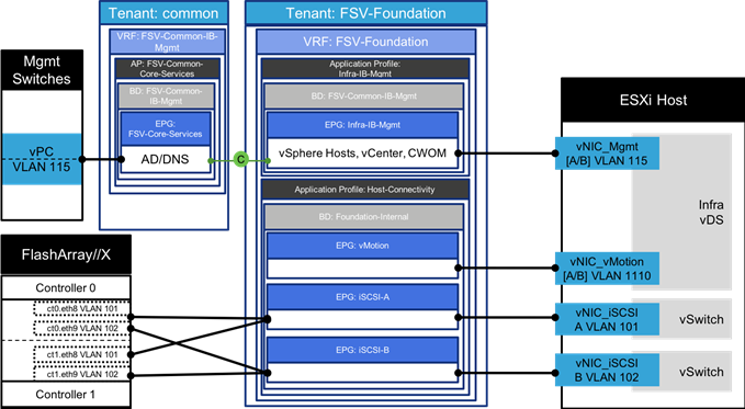
The following ACI constructs are defined the FSV-Foundation Tenant configuration for the iSCSI based storage access:
· Tenant: FSV-Foundation
· VRF: FSV-Foundation
· Bridge Domain: Foundation-Internal
· Application Profile Host-Connectivity consist of three EPGs:
- iSCSI-A statically maps the VLANs associated with iSCSI-A interfaces on the FlashArray//X controllers (VLAN 101) and Cisco UCS Fabric Interconnects (101)
- iSCSI-B statically maps the VLANs associated with iSCSI-B interfaces on the FlashArray//X controllers (VLAN 102) and Cisco UCS Fabric Interconnects (102)
- vMotion statically maps vMotion VLAN (1110) on the Cisco UCS Fabric Interconnects
· Application Profile Infra-IB-Mgmt consist of one EPG:
- Infra-IB-Mgmt statically maps the management VLAN (115) on the Cisco UCS Fabric Interconnects. This EPG is configured to provide the Infra VMs and ESXi hosts access to the existing management network as covered in the next section. This EPG utilizes the bridge domain FSV-Common-IB-Mgmt from the common tenant where it receives the external source of the management VLAN (115) within the FSV-Common-Core-Services EPG.
![]() When associating differing end points into the EPGs, it is not necessary for the VLANs to match, the EPG will handle VLAN association through VXLAN encapsulation in the fabric.
When associating differing end points into the EPGs, it is not necessary for the VLANs to match, the EPG will handle VLAN association through VXLAN encapsulation in the fabric.
Enabling Management Access through Common Tenant
To provide ESXi hosts and VMs access to management segment and common services such as Active Directory (AD), Domain Name Services (DNS), management and monitoring software etc., inter-tenant contracts are utilized. Cisco ACI fabric provides a predefined tenant named common to host the common services that can be easily shared by other tenants in the system. The policies defined in the common tenant are usable by all the tenants without any special configurations. By default, in addition to the locally defined contracts, all the tenants in ACI fabric can “consume” the contracts “provided” in the common tenant.
In the FlashStack environment, access to the management segment is provided through an FSV-Core-Services EPG as shown in Figure 7.
Figure 7 ACI – Providing Management Access through the common Tenant
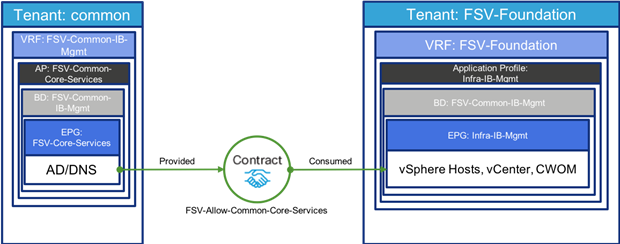
To provide this access:
· EPG FSV-Common-Core-Services is defined in the common tenant.
· FSV-Common-Core-Services statically maps the management VLAN (115) on the current management switch
· FSV-Common-Core-Services “provides” a contract Allow-Common-Core-Services
· ESXi hosts and infrastructure related VMs become part of the EPG Infra-IB-Mgmt in the FSV-Foundation tenant and access the management segment by “consuming” the Allow-Common-Core-Services contract.
· Tenant VMs can also access the common management segment by “consuming” the same contract
· The contract filters can be configured to only allow specific services related ports
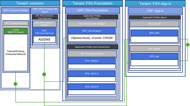
This division of resources sitting on the IB-Mgmt network implements a separation model that can be used when requiring differentiation of access between systems as shown in Figure 8.
Figure 8 Differentiation of access created with Contracts

Onboarding Multi-Tier Application
The ACI constructs for a multi-tier application deployment include defining a new tenant, VRF(s), bridge domain(s), application profile(s), end point group(s), and the contract(s) to allow communication between various tiers of the application. Figure 9 provides an overview of the constructs required for deploying a sample two-tier application.
To deploy a sample two-tier application, following elements are configured:
· A new Tenant called FSV-App-A is defined to host the application
· A VRF called FSV-App-A is defined under the tenant to provide the tenant IP address space
· A bridge domain App-A-Internal is created in the tenant
· An optional bridge domain App-A-External is created in the tenant for additional L2 segregation of incoming user traffic
· An application profile, App-A is utilized to deploy the application.
· Two EPGs, Web and App are associated with the VMM domain to host Web and App/DB tiers of the application
· A contract to allow communication between the two application tiers is defined. This contract is “provided” by the EPG App and “consumed” by the EPG Web
· Each of these App-A EPGs will additionally consume contracts for the FSV-Common-Core-Services EPG to receive access to common infrastructure services like Active Directory
Figure 9 ACI – Attaching Application EPGs with VMware vDS

The following subsections describe the deployment details for how this is connected to the VMware vDS.
Port Group creation for VMware vDS
When application EPGs are attached to a VMware vDS based VMM domain, Cisco APIC assigns VLANs from a pre-defined pool and uses its connection to the VMware vCenter to create a new port groups on the VMware vDS. These port groups are used to deploy application VMs in the appropriate application tier. The port group name is determined using following format: “Tenant_Name | Application Profile_Name | EPG_Name”.
For example, as shown in Figure 9, when the Web EPG is defined under application profile App-A (that belongs to tenant FSV-App-A), a VLAN from the dynamic VLAN pool (2201 in this example) gets assigned to this EPG and a new port group named FSV-App-A|App-A|Web is automatically created on the VMware vDS. When a virtualization administrator assigns a VM NIC to this port group, all the network policies including security (contracts), L4-L7 and QoS automatically get applied to the VM communication.
External Network Connectivity - Shared Layer 3 Out
In order to connect ACI fabric to existing infrastructure, the ACI leaf nodes are connected to the existing enterprise core routers/switches. In this design, a Cisco Nexus 7000 was configured as the enterprise core router. Figure 10 illustrates the physical connectivity details. Each of the leaf switches is physically connected to each of the core router for redundancy using a 10GbE connection.
![]() A pair of adjacent 9372 leaf switches were used in connecting to the enterprise core to utilize 10GbE as dedicated border leaf switches. A single pair of Cisco Nexus 9000 based leaf switches can be used to provide all the FlashStack connectivity including the layer 3 connectivity to existing infrastructure by either selecting a differing model of leaf that supports lower than 40GbE, or utilizing CVR-QSFP-SFP10G QSFP modules in the 93180LC-EX switches used in this design to convert the QSFP ports to SFP ports.
A pair of adjacent 9372 leaf switches were used in connecting to the enterprise core to utilize 10GbE as dedicated border leaf switches. A single pair of Cisco Nexus 9000 based leaf switches can be used to provide all the FlashStack connectivity including the layer 3 connectivity to existing infrastructure by either selecting a differing model of leaf that supports lower than 40GbE, or utilizing CVR-QSFP-SFP10G QSFP modules in the 93180LC-EX switches used in this design to convert the QSFP ports to SFP ports.
Figure 10 ACI – Physical Connectivity to Existing Infrastructure

The design utilizes shared Layer 3 Out configuration to provide routed connectivity to external networks as a shared service. Shared Layer 3 Out functionality can be deployed as a shared service in any tenant. In the FlashStack with ACI validated design, this functionality in configured in the common tenant. As shown in Figure 11, a single “External Routed Network” is configured under tenant common to connect ACI infrastructure to Cisco Nexus 7000s using OSPF. Some of the ACI constructs used in this design are:
· A unique private network and a dedicated external facing bridge domain is defined under the common tenant. This private network (VRF) is setup with OSPF to provide connectivity to external infrastructure. The private network configured under the tenant common is called vrf-Common-Outside is and the bridge domain is called bd-Common-Outside.
· Four unique VLANs (sub-interfaces) are configured between ACI leaf switches and the core router; one for each of the four physical paths. The VLANs utilized are 301-304 (as seen in Figure 8).
· OSPF routing is enabled on all the four paths between the Cisco Nexus 9000 and the Cisco Nexus 7000 enterprise router
· On Cisco ACI fabric, common tenant learns a default route from the Cisco Nexus 7000 switches and advertises routable subnets to the core infrastructure.
· Cisco Nexus 7000 switches can optionally use OSPF metrics to influence path preferences.
Figure 11 ACI - Connectivity to Existing Infrastructure

After common tenant is configured with the Layer-3 connectivity, all the other tenants can share this connection through contracts to access existing enterprise infrastructure as shown in Figure 12. The external routed network, Nexus-7K, “provides” a contract named Allow-Outside-All. When the application tenant EPGs “consume” this contract, the “public” IP subnet(s) defined under the application tenant EPGs get advertised to the enterprise network. The application EPGs also learns the default route from the tenant common. The filters under the contract control the traffic that can be sent and received from the shared L3 out. In the FlashStack with ACI design, each tenant is configured with a dedicated VRF as well as a dedicated bridge domain and these constructs are not shared with other tenants.
![]() Tenant advertised prefixes for a shared Layer 3 out must to be unique; overlapping tenant subnets are not supported.
Tenant advertised prefixes for a shared Layer 3 out must to be unique; overlapping tenant subnets are not supported.
Figure 12 ACI – Tenant Contracts for Shared L3 Out

FlashStack with Cisco ACI - Components
FlashStack with ACI is designed to be fully redundant in the compute, network, and storage layers. There is no single point of failure from a device or traffic path perspective. Figure 13 illustrates how the various elements are connected together.
Figure 13 FlashStack Design with Cisco ACI and FlashArray//X

![]() Adjacent leaf switches used for management connectivity as well as shared L3 connectivity shown elsewhere in this design, are not pictured in this topology.
Adjacent leaf switches used for management connectivity as well as shared L3 connectivity shown elsewhere in this design, are not pictured in this topology.
Fabric: Link aggregation technologies play an important role in FlashStack with ACI providing improved aggregate bandwidth and link resiliency across the solution stack. The Cisco Unified Computing System, and Cisco Nexus 9000 platforms support active port channeling using 802.3ad standard Link Aggregation Control Protocol (LACP). Port channeling is a link aggregation technique offering link fault tolerance and traffic distribution (load balancing) for improved aggregate bandwidth across member ports. In addition, the Cisco Nexus 9000 series features virtual Port Channel (vPC) capabilities. vPC allows links that are physically connected to two different Cisco Nexus 9000 Series devices to appear as a single "logical" port channel to a third device, essentially offering device fault tolerance. Note in Figure 13 that vPC peer links are no longer needed. The peer link is handled in the leaf to spine connections and any two leaves in an ACI fabric can be paired in a vPC. The Cisco UCS Fabric Interconnects benefit from the Cisco Nexus vPC abstraction, gaining link and device resiliency as well as full utilization of a non-blocking Ethernet fabric. The FlashArray iSCSI ports connect into the Cisco Nexus 9000 and are independently reachable for each FlashArray controller interface configured as an iSCSI adapter.
Compute: Each Cisco UCS 5108 chassis is connected to the FIs using a pair of ports from each IO Module for a combined 40G uplink as illustrated in Figure 14. Optional configurations could include Cisco UCS C-Series connected by directly attaching the Cisco UCS C-Series servers into the FIs to provide a uniform look-and-feel across blade and standalone servers within a common Cisco UCS Manager interface.
Figure 14 FlashStack Compute Connectivity

![]() Cisco UCS C-Series servers are supported within FlashStack, but were not included as part of the validation associated with this CVD.
Cisco UCS C-Series servers are supported within FlashStack, but were not included as part of the validation associated with this CVD.
Storage: The ACI-based FlashStack design is an end-to-end IP-based storage solution that supports SAN access by using iSCSI. The solution provides a 10/40GbE fabric that is defined by Ethernet uplinks from the Cisco UCS Fabric Interconnects and Pure Storage FlashArrays connected to the Cisco Nexus switches as shown in Figure 15. Optionally, the ACI-based FlashStack design can be configured for SAN boot or application LUN access by using Fibre Channel (FC) by bringing Cisco MDS switches into the design to sit in parallel to the ACI network, but this is not covered in the design.
Figure 15 FlashStack Storage Connectivity

The virtual environment this supports is within VMware vSphere 6.5 U1, and includes virtual management and automation components from Cisco and Pure Storage built into the solution, or as optional add-ons.
The implementation section of this document will provide a low-level example of steps to deploy this base architecture that may need some adjustments depending on the customer environment. These steps include physical cabling, network, storage, compute, and virtual device configurations.
Solution Architecture
The FlashStack architecture brings together the proven data center strengths of the Cisco UCS compute and Cisco Nexus network switches delivering storage from the leading visionary in all flash arrays. This collaboration creates a simple, yet powerful and resilient data center footprint for the modern enterprise. The design, illustrated in Figure 16, is physically redundant at each point within topology, providing high speed NVMe storage, the latest Intel Scalable processors, end to end 40Gb connectivity, and a secure, scalable architecture built with Cisco ACI.
Figure 16 FlashStack Physical Topology

To further explain the interconnection between these components, look at the first layer of the UCS compute illustrated in Figure 17:
Figure 17 FlashStack UCS Physical Topology

The Cisco UCS B200 M5 server is shown to be equipped with the VIC 1340 Converged Network Adapter and a Port Expander, allowing an aggregate 80GBps of bandwidth between the server’s connections to the Cisco UCS 2304 Fabric Extender (IOM – I/O Module). Each port within the VIC (0 vs 1, mapping to the vs B sides of the fabric), connects into eight 10G KR lanes coming through the UCS 5108 Chassis, four from each IOM that are automatically port-channeled. Continuing from the IOM, there are two 40G connections coming from their respective Cisco UCS 6332-16UP Fabric Interconnects. These connections going between the IOM and the Fabric Interconnects carry converged Ethernet and Fibre Channel over Ethernet traffic, that is configured as a port channel by the chassis discovery policy within the Cisco UCS Manager setup.
Within the next section of connectivity shown in Figure 18, there are virtual port channels (vPC) of 40G Ethernet connections configured by the ACI fabric to present Nexus 93180LC-EX Leaf switches as a single switch to each of the Fabric Interconnects.
Figure 18 Fabric Interconnect to ACI Leaves

Reaching the next layer of connections, the ACI Leaf to Spine connections are shown in Figure 19:
Figure 19 ACI Leaves to ACI Spines

· Cisco Nexus 93180LC-EX – 100Gb capable, LAN connectivity to the Cisco UCS compute resources and handling iSCSI traffic between the Cisco UCS Fabric Interconnect and the Pure Storage FlashArray//X, configured as ACI Leafs.
· Cisco Nexus 9504 – Modular switch acting as the ACI Spines.
· Cisco UCS 6332-16UP Fabric Interconnect – Unified management of Cisco UCS compute, and that compute’s access to storage and networks.
· Cisco UCS B200 M5 – High powered, versatile blade server, which was conceived for virtual computing.
· Pure Storage FlashArray//X70 – All flash storage implemented with inline compression and deduplication in a simple and resilient manner.
Virtualization layer components and managers of the architecture also include:
· Cisco UCS Manager – Management delivered through the Fabric Interconnect, providing stateless compute, and policy driven implementation of the servers it manages.
· Cisco UCS Director (optional) – Automation of the deployment of Cisco infrastructure, complete provisioning of servers as vSphere resources, and accompanying storage from the Pure Storage FlashArray.
· Cisco UCS Manager Plugin for VMware vSphere Web Client – Cisco UCS Manager functionality brought into the vCenter web based interface.
· Cisco ACI Plugin for VMware vSphere Web Client – Basic ACI configuration and monitoring features from within the vCenter.
· VMware vSphere and VMware vCenter – Hypervisor and Virtual Machine Manager.
· VMware vDS – Distributed Virtual Switch for the vSphere environment.
· Pure Storage vSphere Web Client Plugin – Easy to use management of volumes within the vSphere Web Client.
Additional Design Considerations
Management Connectivity
Out-of-band management is handled by an independent switch that could be one currently in place in the customer’s environment. Each FlashStack physical device had its management interface carried through this Out-of-band switch, with in-band management carried as a differing VLAN within the solution for ESXi, vCenter and other virtual management components.
Out-of-band configuration for the components configured as in-band could be enabled, but would require additional uplink ports on the 6332-16UP Fabric Interconnects if the out of band management is kept on a separate out of band switch. A disjoint layer-2 configuration can then be used to keep the management and data plane networks completely separate. This would require 2 additional vNICs (for example, OOB-Mgmt-A, OOB-Mgmt-B) on each server, which are associated with the management uplink ports.
Jumbo Frames
Jumbo frames are a standard recommendation across Cisco designs to help leverage the increased bandwidth availability of modern networks. To take advantage of the bandwidth optimization and reduced consumption of CPU resources gained through jumbo frames, they were configured at each network level to include the virtual switch and virtual NIC.
This optimization is relevant for VLANs that stay within the pod, and do not connect externally. Any VLANs that are extended outside of the pod should be left at the standard 1500 MTU to prevent drops from any connections or devices not configured to support a larger MTU.
Cisco UCS Server vSphere Configuration
Cisco UCS B-Series servers are installed with ESXi 6.5 U1 using Cisco VIC 1340 adapters to provide separate virtual NICs for the combined management and infrastructure traffic versus application virtual NICs. Within vSphere these hosts were further divided into differing clusters that supported either the virtual infrastructure management components, or the production application virtual machines. For each of these clusters, both VMware High Availability (HA) and VMware Distributed Resource Scheduler (DRS) are enabled.
VMware HA is turned on for the clusters to allow automated recovery of active VMs in the event of a physical failure in the underlying ESXi host it resides upon. Depending upon application priority or being up versus having resource guarantees, HA Admission Control might be turned off to allow power-on of VMs in failure scenarios where resources may be constrained.
For VMware DRS, Automation Level should be set as comfortable to the customer. Further into DRS configuration certain infrastructure and application VMs should be set up under DRS Groups Manager and Rules to have placement rules applied for them. These rules can be set to include:
· Keep Virtual Machines Together – For VMs that work with each other that can take advantage of increased performance by being adjacent to each other within the same hypervisor.
· Separate Virtual Machines – For VMs with some form of application level high availability to guarantee that member VMs are not impacted by the same hardware fault.
· Virtual Machines to Hosts - VM to host association that may be relevant for reasons such as licensing.
A fixed VMware vDS (virtual distributed switches) was configured for Infrastructure to support the management and vMotion traffic. This infrastructure vDS could have instead been a set of standard vSwitches, but were deployed as a vDS to allow for a quick, standardized virtual network configuration of added hosts as the FlashStack grows. Separate vNIC uplinks have been created for management versus vMotion traffic, but are brought in as uplinks to the common Infrastructure vDS and associated to the appropriate distributed port group through pinning. This pinning is set to make management traffic active on the A side of the fabric and vMotion active on the B side of the fabric, allowing both types of traffic that are primarily local to the ESXi cluster to stay within one of these respective sides of the fabric to avoid an unnecessary hop up through the Nexus leaf switches. iSCSI traffic carried within standard vSwitches.
For the Application traffic, the Cisco APIC is leveraged to implement a vDS within the vCenter that the APIC will control as port groups and VLANs are allocated. The layout for the virtual switching configuration is illustrated in Figure 20.
Figure 20 vDS Shown on an iSCSI Booted Cisco UCS B200 M5 Server

Additional standard tasks and best practices include the following:
· A vMotion vmkernel interface is added to each host during the initial setup.
· NTP is set on each ESXi server.
· Shared storage added to each ESXi host in FlashStack using the Pure Storage vSphere Web Plugin.
· Cisco ESXi nenic network adapter drivers were applied to each server.
· An ESXi swap datastore is specified to easily allow for separation of VM swapfiles, to make them excludable from snapshots and backup purposes.
Software Revisions
Table 1 lists the software versions for hardware and virtual components used in this solution. Each version used has been certified within interoperability matrixes supported by Cisco, Pure Storage, and VMware. For more supported version information, consult the following sources:
· Cisco UCS Hardware and Software Interoperability Tool
· Pure Storage Interoperability (note, this interoperability list requires a support login form Pure)
· Cisco ACI Recommended Release
· Cisco ACI Virtualization Compatibility
![]() If you select a version that differs from the validated versions below, it is highly recommended to read the release notes of the selected version to be aware of any changes to features or commands that may have occurred.
If you select a version that differs from the validated versions below, it is highly recommended to read the release notes of the selected version to be aware of any changes to features or commands that may have occurred.
| Layer | Device | Image | Comments |
| Compute | Cisco UCS Fabric Interconnects 6300 Series, UCS B-200 M5 | 3.2(3d)* | Includes the Cisco UCS IOM 2304 and Cisco UCS VIC 1340 |
| Network | Cisco Nexus 9000 ACI Mode | 13.1(1i) |
|
|
| Cisco APIC | 3.1(1i) |
|
| Storage | Pure Storage FlashArray//X70 | 4.10.5 |
|
| Software | Cisco UCS Manager | 3.2(3d)* | Initial validation on 3.2(2e) |
|
| VMware vSphere ESXi Cisco Custom ISO | 6.5 U1* | VMware Source ESXi650-201803401-BG and ESXi650-201803402-BG applied after initial validation |
|
| VMware vSphere nenic driver for ESXi | 1.0.13.0 |
|
|
| VMware vCenter | 6.5 U1g* | Initial validation on 6.5 U1e |
|
| Pure Storage vSphere Web Client Plugin | 3.0 | The 2.5.1 version is provided with Purity 4.10.5, but will default to provisioning of VMFS-5 datastores within the plugin. To enable the option of VMFS-6 through the plugin, a support request can be made with Pure to enable access to the 3.0 plugin. |
|
| Cisco UCSM plugin for the Sphere Web Client | 2.0.3 |
Configuration Workflow
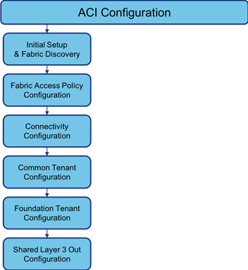
Figure 21 illustrates the configuration workflow used in this solution.
Figure 21 Configuration Workflow

The FlashStack with ACI deployment workflow will require configuration of certain components before working on others. The order of steps in this implementation guide are laid out with the intent of best capturing the sequence of those dependencies.
Configuration Guidelines
This document details the step by step configuration of a fully redundant and highly available Virtual Server Infrastructure built on Cisco and Pure Storage components. References are made to which component is being configured with each step, either 01 or 02 or A and B. For example, controller-1 and controller-2 are used to identify the two controllers within the Pure Storage FlashArray//X that are provisioned with this document, and Cisco Nexus A or Cisco Nexus B identifies the pair of Cisco Nexus leaf switches that are configured. The Cisco UCS fabric interconnects are similarly configured. Additionally, this document details the steps for provisioning multiple Cisco UCS hosts, and these examples are identified as: VM-Host-iSCSI-01, VM-Host-iSCSI-02 to represent iSCSI booted infrastructure and production hosts deployed to the fabric interconnects in this document.
This document is intended to enable you to fully configure the customer environment. In this process, various steps require you to insert customer-specific naming conventions, IP addresses, and VLAN schemes, as well as to record appropriate MAC addresses. Table 2 describes the VLANs necessary for deployment as outlined in this guide.
| VLAN Name | VLAN Purpose | ID Used in Validating this Document | Customer Deployed Value |
| Native | VLAN to which untagged frames are assigned | 2 |
|
| iSCSI-A | VLAN for iSCSI A | 101 |
|
| iSCSI-B | VLAN for iSCSI B | 102 |
|
| IB-Mgmt | Common Infrastructure within the FlashStack | 115 |
|
| vMotion | VLAN for VMware vMotion | 1110 |
|
| VM-App-[2201-2220] | VLAN for Production VM Interfaces | 2201-2220 |
|
FlashStack Cabling
This section details a cabling example for a FlashStack environment. To make connectivity clear in this example, the tables include both the local and remote port locations.
This document assumes that out-of-band management ports are plugged into an existing management infrastructure at the deployment site.
Figure 22 illustrates the cabling configuration used in this FlashStack design.
Figure 22 FlashStack Cabling in the Validated Topology

Table 3 through Table 8 provide the connectivity information for the components shown in Figure 22.
![]() Ports 25-32 on the Nexus 93180LC-EX switches come as fabric ports intended for Spine connections. Uplinks for the UCS and FlashArray have been set within ports 1-24, but ports 25-28 can additionally be adjusted from fabric ports to uplink ports if necessary.
Ports 25-32 on the Nexus 93180LC-EX switches come as fabric ports intended for Spine connections. Uplinks for the UCS and FlashArray have been set within ports 1-24, but ports 25-28 can additionally be adjusted from fabric ports to uplink ports if necessary.
Table 3 Cisco Nexus 93180LC-EX-A Cabling Information
| Local Device | Local Port | Connection | Remote Device | Remote Port |
| Cisco Nexus 93180LC-EX A | Eth1/23 | 40GbE | FlashArray//X70 Controller 1 | CT0.ETH8 |
| Eth1/24 | 40GbE | FlashArray//X70 Controller 2 | CT1.ETH8 | |
| Eth1/1 | 40GbE | Cisco UCS 6332-16UP FI A | Eth 1/39 | |
| Eth1/2 | 40GbE | Cisco UCS 6332-16UP FI B | Eth 1/39 | |
| Eth1/31 | 40GbE | Cisco Nexus 9504 A (Spine) | Eth 4/3 | |
| Eth1/32 | 40GbE | Cisco Nexus 9504 B (Spine) | Eth 4/3 | |
| MGMT0 | GbE | GbE management switch | Any |
Table 4 Cisco Nexus 93180LC-EX-B Cabling Information
| Local Device
| Local Port | Connection | Remote Device | Remote Port |
| Cisco Nexus 93180LC-EX B | Eth1/23 | 40GbE | FlashArray//X70 Controller 1 | CT0.ETH9 |
| Eth1/24 | 40GbE | FlashArray//X70 Controller 2 | CT1.ETH9 | |
| Eth1/1 | 40GbE | Cisco UCS 6332-16UP FI A | Eth 1/40 | |
| Eth1/2 | 40GbE | Cisco UCS 6332-16UP FI B | Eth 1/40 | |
| Eth1/31 | 40GbE or 100GbE | Cisco Nexus 9504 A (Spine) | Eth 4/4 | |
| Eth1/32 | 40GbE or 100GbE | Cisco Nexus 9504 B (Spine) | Eth 4/4 | |
| MGMT0 | GbE | GbE management switch | Any |
Table 5 Cisco UCS 6332-16UP FI A Cabling Information
| Local Device | Local Port | Connection | Remote Device | Remote Port |
| Cisco UCS 6332-16UP FI A | Eth1/17 | 40GbE | Cisco UCS Chassis 1 2304 FEX A | IOM 1/1 |
| Eth1/18 | 40GbE | Cisco UCS Chassis 1 2304 FEX A | IOM 1/2 | |
| Eth1/39 | 40GbE | Cisco Nexus 93180LC-EX A | Eth1/1 | |
| Eth1/40 | 40GbE | Cisco Nexus 93180LC-EX B | Eth1/1 | |
| MGMT0 | GbE | GbE management switch | Any | |
| L1 | GbE | Cisco UCS 6332-16UP FI B | L1 | |
| L2 | GbE | Cisco UCS 6332-16UP FI B | L2 |
Table 6 Cisco UCS 6332-16UP FI B Cabling Information
| Local Device | Local Port | Connection | Remote Device | Remote Port |
| Cisco UCS 6332-16UP FI B | Eth1/17 | 40GbE | Cisco UCS Chassis 1 2304 FEX B | IOM 1/1 |
| Eth1/18 | 40GbE | Cisco UCS Chassis 1 2304 FEX B | IOM 1/2 | |
| Eth1/39 | 40GbE | Cisco Nexus 93180LC-EX A | Eth1/2 | |
| Eth1/40 | 40GbE | Cisco Nexus 93180LC-EX B | Eth1/2 | |
| MGMT0 | GbE | GbE management switch | Any | |
| L1 | GbE | Cisco UCS 6332-16UP FI B | L1 | |
| L2 | GbE | Cisco UCS 6332-16UP FI B | L2 |
Table 7 Pure Storage FlashArray//X70 Controller 1 Cabling Information
| Local Device | Local Port | Connection | Remote Device | Remote Port |
| FlashArray//X70 Controller 1 | Eth0 | GbE | GbE management switch | Any |
| ETH8 | 40GbE | Cisco Nexus 93180LC-EX A | Eth 1/23 | |
| ETH9 | 40GbE | Cisco Nexus 93180LC-EX B | Eth 1/23 |
Table 8 Pure Storage FlashArray//X70 Controller 2 Cabling Information
| Local Device | Local Port | Connection | Remote Device | Remote Port |
| FlashArray//X70 Controller 2 | Eth0 | GbE | GbE management switch | Any |
| ETH8 | 40GbE | Cisco Nexus 93180LC-EX A | Eth 1/24 | |
| ETH9 | 40GbE | Cisco Nexus 93180LC-EX B | Eth 1/24 |
Figure 23 ACI Configuration Workflow
Initial Setup and Fabric Discovery
Physical Connectivity
Physical cabling should be completed by following the diagram and table references in the previous section FlashStack Cabling.
Cisco Application Policy Infrastructure Controller (APIC) Verification
This section verifies the setup the Cisco APIC. To verify the APIC, complete the following steps:
1. Log into the APIC GUI using a web browser by browsing to the out-of-band IP address configured for APIC. Login with the admin user id and password.

2. Take appropriate action to close any warning or information screens.
3. At the top in the APIC home page, select the System tab followed by Controllers.
4. On the left, select the Controllers folder. Verify that at least 3 APICs are available and have redundant connections to the fabric.

![]() Only one APIC is present in the lab setting shown above, but in a production setting there should be 3 APICs present.
Only one APIC is present in the lab setting shown above, but in a production setting there should be 3 APICs present.
Cisco ACI Fabric Discovery
This section details the steps for adding the two Nexus 93180LC-EX leaf switches to the fabric. These switches are automatically discovered in the ACI Fabric and are manually assigned node IDs. To add the leaf switches, perform the following steps:
1. At the top in the APIC home page, select the Fabric tab, and Inventory within the options of Fabric.
2. In the left pane, select and expand Fabric Membership.
3. The two 93180LC-EX Leaf Switches will be listed on the Fabric Membership page with Node ID 0 as shown:

4. Connect to the two Nexus 93180LC-EX leaf switches using serial consoles and login in as admin with no password (press enter). Use show inventory to get the leaf’s serial number.
(none) login: admin
********************************************************************************
Fabric discovery in progress, show commands are not fully functional
Logout and Login after discovery to continue to use show commands.
********************************************************************************
(none)# show inventory
NAME: "Chassis", DESCR: "Nexus C93180LC-EX chassis"
PID: N9K-C93180LC-EX , VID: V02 , SN: FDO21471CTF
NAME: "Slot 1 ", DESCR: "24x40G/12x100G "
PID: N9K-C93180LC-EX , VID: V02 , SN: FDO21471CTF
NAME: "GEM ", DESCR: "6x40/100G Switch "
PID: N9K-C93180LC-EX , VID: V02 , SN: FDO21471CTF
5. Match the serial numbers from the leaf listing to determine the A and B switches under Fabric Membership.
6. In the APIC GUI, under Fabric Membership, double click the A leaf in the list. Enter a Node ID and a Node Name for the Leaf switch and click Update.

7. Repeat step 6 for the B leaf in the list.
8. Click Topology in the left pane, then select View Pod for the configured Pod. The discovered ACI Fabric topology will appear. It may take a few minutes for the Nexus 93180LC-EX Leaf switches to appear and you will need to click the refresh button for the complete topology to appear.

Initial ACI Fabric Setup Verification
This section details the steps for initial setup of the Cisco ACI Fabric, where the software release is validated, out of band management IPs are assigned to the new leaves, NTP setup is verified, and the fabric BGP route reflectors are verified.
Software Upgrade
This document was validated with ACI software release 3.1(1i). Select Admin -> Firmware within the top tabs, and Fabric Node Firmware in the left pane. All switches should show the same firmware release and the release version should be at minimum n9000-13.1(1i). The switch software version should also match the APIC version.
1. If a software upgrade is needed, begin the process within the APIC GUI, by selecting from the top Admin > Firmware:

2. Click Admin > Firmware > Controller Firmware. If all APICs are not at the same release at a minimum of 3.1(1i), follow the Cisco APIC Controller and Switch Software Upgrade and Downgrade Guide to upgrade both the APICs and switches to a minimum release of 3.1(1i) on APIC and 13.1(1i) on the switches.
Setting up Out of Band Management IP Addresses for New Leaf and Switches
To add out of band management interfaces for all the switches in the ACI Fabric, complete the following steps:
1. Select Tenants > mgmt.
2. Expand Tenant mgmt on the left. Right-click Node Management Addresses and select Create Static Node Management Addresses.
3. Enter the node number range for the new leaf switches (203-204 in this example).
4. Select the checkbox for Out-of-Band Addresses.
5. Select default for Out-of-Band Management EPG.
6. Considering that the IPs will be applied in a consecutive range of two IPs, enter a starting IP address and netmask in the Out-Of-Band IPV4 Address field.

7. Enter the out of band management gateway address in the Gateway field.
8. Click SUBMIT, then click YES.
9. On the left, expand Node Management Addresses and select Static Node Management Addresses. Verify the mapping of IPs to switching nodes.

Direct out-of-band access to the switches should now be available for SSH.
Verifying Time Zone and NTP Server
This procedure allows customers to verify the setup of an NTP server for synchronizing the fabric time. To verify NTP setup in the fabric, complete the following steps:
1. Select and expand Fabric > Fabric Policies > Pod Policies > Policies > Date and Time.
2. Select default. In the Datetime Format - default pane, verify the correct Time Zone is selected and that Offset State is enabled. Adjust as necessary and click Submit and Submit Changes.
3. On the left, select Policy default. Verify that at least one NTP Server is listed.

![]() If necessary, on the right use the + sign to add NTP servers accessible on the out of band management subnet. Enter an IP address accessible on the out of band management subnet and select the default (Out-of-Band) Management EPG. Click Submit to add the NTP server. Repeat this process to add all NTP servers.
If necessary, on the right use the + sign to add NTP servers accessible on the out of band management subnet. Enter an IP address accessible on the out of band management subnet and select the default (Out-of-Band) Management EPG. Click Submit to add the NTP server. Repeat this process to add all NTP servers.
Verifying Domain Name Servers
To verify optional DNS in the ACI fabric,
1. Select and expand Fabric > Fabric Policies > Global Policies > DNS Profiles > default.
2. Verify the DNS Providers and DNS Domains.
3. If necessary, in the Management EPG drop-down list, select the default (Out-of-Band) Management EPG. Use the + signs to the right of DNS Providers and DNS Domains to add DNS servers and the DNS domain name. Note that the DNS servers should be reachable from the out-of-band management subnet. Click SUBMIT to complete the DNS configuration.

Defining BGP Route Reflectors
In this ACI deployment, both the spine switches should be set up as BGP route-reflectors to distribute the leaf routes throughout the fabric. This set of steps can be skipped if the BGP route reflectors have been previously set up. To define the BGP Route Reflector, complete the following steps:
1. Select and expand System > System Settings > BGP Route Reflector.
2. Verify that a unique Autonomous System Number has been selected for this ACI fabric. If necessary, use the + sign on the right to add the two spines to the list of Route Reflector Nodes. Click SUBMIT to complete configuring the BGP Route Reflector.

3. To verify the BGP Route Reflector has been enabled, select and expand Fabric > Fabric Policies > Pod Policies > Policy Groups. Under Policy Groups make sure a policy group has been created and select it. The BGP Route Reflector Policy field should show “default.”

4. If a Policy Group has not been created, on the left, right-click Policy Groups under Pod Policies and select Create Pod Policy Group.
5. In the Create Pod Policy Group window, name the Policy Group pod1-policygrp. Select the default BGP Route Reflector Policy.
6. Click SUBMIT to complete creating the Policy Group.
7. On the left expand Profiles under Pod Policies and select Pod Profile default > default.
8. Verify that the configured Fabric Policy Group identified above (ppg-Pod1 in our example) is selected. If the Fabric Policy Group is not selected, use the drop-down list to select it and click Submit.

Fabric Access Policy Configuration
This section details the steps to create various access policies creating parameters for CDP, LLDP, LACP, etc. These policies are used during vPC and VM domain creation. In an existing fabric, these policies may already exist. The existing policies can be used if configured the same way as listed.
Create Link Level Policies
This procedure will create link level policies for setting up the 1Gbps, 10Gbps, and 40Gbps link speeds.
Prior to creating Link Level Policies, you need to define the Fabric Access Policies.
To define fabric access policies, complete the following steps:
1. Log into the APIC GUI.
2. Navigate to Fabric > Access Policies > Interface Policies > Policies.
To create Link Level Policies, complete the following steps:
1. In the left pane, right-click Link Level and select Create Link Level Policy.
2. Name the policy as 1Gbps-Auto and select the 1Gbps Speed.

3. Click Submit to complete creating the policy.
4. In the left pane, right-click on Link Level and select Create Link Level Policy.
5. Name the policy 10Gbps-Auto and select the 10Gbps Speed.
6. Click Submit to complete creating the policy.
7. In the left pane, right-click on Link Level and select Create Link Level Policy.
8. Name the policy 40Gbps-Auto and select the 40Gbps Speed.
9. Click Submit to complete creating the policy.
Create CDP Policy
To create policies to enable or disable CDP on a link, complete the following steps:
1. In the left pane, right-click CDP interface and select Create CDP Interface Policy.
2. Name the policy as CDP-Enabled and enable the Admin State.

3. Click Submit to complete creating the policy.
4. In the left pane, right-click on the CDP Interface and select Create CDP Interface Policy.
5. Name the policy CDP-Disabled and disable the Admin State.
6. Click Submit to complete creating the policy.
Create LLDP Interface Policies
To create policies to enable or disable LLDP on a link, complete the following steps:
1. In the left pane, right-click LLDP lnterface and select Create LLDP Interface Policy.
2. Name the policy as LLDP-Enabled and enable both Transmit State and Receive State.

3. Click Submit to complete creating the policy.
4. In the left, right-click the LLDP lnterface and select Create LLDP Interface Policy.
5. Name the policy as LLDP-Disabled and disable both the Transmit State and Receive State.
6. Click Submit to complete creating the policy.
Create Port-Channel Policy
To create policies to set LACP active mode configuration, LACP Mode On configuration, and the MAC-Pinning mode configuration, complete the following steps:
1. In the left pane, right-click the Port Channel and select Create Port Channel Policy.
2. Name the policy as LACP-Active and select LACP Active for the Mode. Do not change any of the other values.

3. Click Submit to complete creating the policy.
4. In the left pane, right-click Port Channel and select Create Port Channel Policy.
5. Name the policy as MAC-Pinning and select MAC Pinning-Physical-NIC-load for the Mode. Do not change any of the other values.

6. Click Submit to complete creating the policy.
7. In the left pane, right-click Port Channel and select Create Port Channel Policy.
Create BPDU Filter/Guard Policies
To create policies to enable or disable BPDU filter and guard, complete the following steps:
1. In the left pane, right-click Spanning Tree Interface and select Create Spanning Tree Interface Policy.
2. Name the policy as BPDU-FG-Enabled and select both the BPDU filter and BPDU Guard Interface Controls.

3. Click Submit to complete creating the policy.
4. In the left pane, right-click Spanning Tree Interface and select Create Spanning Tree Interface Policy.
5. Name the policy as BPDU-FG-Disabled and make sure both the BPDU filter and BPDU Guard Interface Controls are cleared.
6. Click Submit to complete creating the policy.
Create Global VLAN Policy
This procedure will create policies to enable global scope for all the VLANs.
1. In the left pane, right-click on the L2 Interface and select Create L2 Interface Policy.
2. Name the policy as VLAN-Scope-Global and make sure Global scope is selected. Do not change any of the other values.

3. Click Submit to complete creating the policy.
Create Firewall Policy
To create policies to disable Firewall, complete the following steps:
1. In the left pane, right-click Firewall and select Create Firewall Policy.
2. Name the policy Firewall-Disabled and select Disabled for Mode. Do not change any of the other values.

3. Click Submit to complete creating the policy.
Connectivity Configuration
This subsection details the steps to setup vPCs and individual interfaces coming from the leaf used for connectivity.
![]() This deployment guide explains the configuration for a pre-existing Cisco Nexus management switch. Customers can adjust the management configuration depending on their connectivity setup. The In-Band Management Network will provide connectivity of Management Virtual Machines and Hosts in the ACI fabric to existing services on the In-Band Management network outside of the ACI fabric. In this validation, a 10GE vPC from two 10GE capable leaf switches in the fabric is connected to a port channel on a Nexus 5K switch outside the fabric. This VPC can also be created on the Nexus 93180LC-EX leaves by using Cisco QSA adapter (CVR-QSFP-SFP10G) with SFP-10G-SR.
This deployment guide explains the configuration for a pre-existing Cisco Nexus management switch. Customers can adjust the management configuration depending on their connectivity setup. The In-Band Management Network will provide connectivity of Management Virtual Machines and Hosts in the ACI fabric to existing services on the In-Band Management network outside of the ACI fabric. In this validation, a 10GE vPC from two 10GE capable leaf switches in the fabric is connected to a port channel on a Nexus 5K switch outside the fabric. This VPC can also be created on the Nexus 93180LC-EX leaves by using Cisco QSA adapter (CVR-QSFP-SFP10G) with SFP-10G-SR.
VPC - Management Switch
To setup vPCs for connectivity to the existing In-Band Management Network, complete the following steps:
1. Connect to the APIC GUI and select Fabric > Access Policies > Quick Start.

2. In the right pane, select Configure an interface, PC and VPC.
3. In the configuration window, configure a VPC domain between the leaf switches by clicking “+” under VPC Switch Pairs. If a VPC Domain already exists between the two switches being used for this vPC, skip to step 8.

4. Enter a VPC Domain ID (10 in this example).
5. From the drop-down list, select Switch A and Switch B IDs to select the two leaf switches.

6. Click SAVE.
7. Click the “+” under Configured Switch Interfaces.

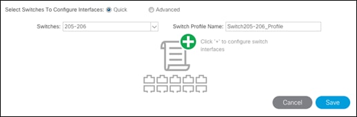
8. From the Switches drop-down list on the right, select both the leaf switches being used for this vPC.
9. Leave the system generated Switch Profile Name in place.
10. Click the big green “+” to configure switch interfaces

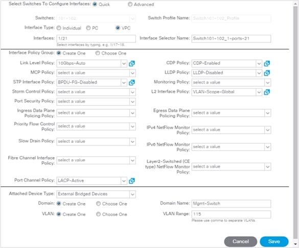
11. Configure the various fields as shown in the screenshot below. In this screenshot, port 1/21 on both leaf switches is connected to Cisco catalyst switch using 10Gbps links:
a. Interface Type: VPC
b. Interfaces: 1/21
c. (optional change) Interface Selector Name: Switch101-102_1-ports-21
d. Link Level Policy: 10Gbps-Link
e. STP Interface Policy: BPDU-FG-Disabled
f. Port Channel Policy: LACP-Active
g. CPD Policy: CDP-Enabled
h. LLDP Policy: LLDP-Disabled
i. L2 Interface Policy: VLAN-Scope-Global
j. Attached Device Type: External Bridged Devices
k. Domain Name: Mgmt-Switch
l. VLAN Range: 115
![]() CDP has been selected for the discovery policy in this configuration, but this can be changed to LLDP if desired, as long as the change is consistent across all VPC, UCS and VSwitch Policy configuration. One of these discovery policies will need to be enabled for the vDS configuration to work.
CDP has been selected for the discovery policy in this configuration, but this can be changed to LLDP if desired, as long as the change is consistent across all VPC, UCS and VSwitch Policy configuration. One of these discovery policies will need to be enabled for the vDS configuration to work.
12. Click Save.
13. Click Save again to finish the configuring switch interfaces
14. Click Submit.
![]() To validate the configuration, log into the Nexus switch and verify the port-channel is up (show port-channel summary).
To validate the configuration, log into the Nexus switch and verify the port-channel is up (show port-channel summary).
VPC – UCS Fabric Interconnects
To setup vPCs for connectivity to the UCS Fabric Interconnects, complete the following steps:
![]() The VLANs configured for Cisco UCS are shown in Table 9.
The VLANs configured for Cisco UCS are shown in Table 9.

Table 9 VLANs for Cisco UCS Hosts
| Name | VLAN |
| Native | 2 |
| iSCSI-A | 101 |
| iSCSI-B | 102 |
| vMotion | 1110 |
| Infra-IB-Mgmt | 115 |
1. Begin the configuration from the APIC GUI by selecting Fabric > Access Policies > Quick Start.
2. In the right pane under Steps, select Configure and interface, PC and VPC.
3. In the configuration window, configure a VPC domain between the 93180LC-EX leaf switches by clicking “+” under VPC Switch Pairs.

4. Enter a VPC Domain ID (10 in this example).
5. From the drop-down list, select 93180LC-EX Switch A and 93180LC-EX Switch B IDs to select the two leaf switches.

6. Click Save.
7. Click the “+” under Configured Switch Interfaces.
8. Select the two Nexus 93180LC-EX switches under the Switches pulldown.
9. Click ![]() on the right to add switch interfaces
on the right to add switch interfaces
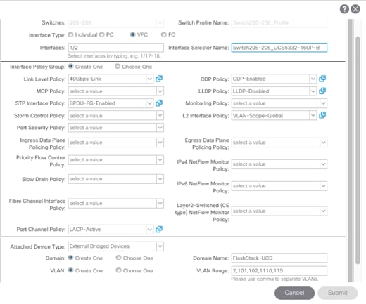
10. Configure various fields as shown in the screenshot below, selecting or entering the following or equivalent values for connecting the Nexus 93180LC-EX leafs to the Cisco UCS Fabric Interconnect A:
a. Interface Type: VPC
b. Interfaces: 1/1
c. (optional change) Interface Selector Name: Switch205-206_UCS6332-16UP-A
d. Link Level Policy: 40Gbps-Link
e. STP Interface Policy: BPDU-FG-Enabled
f. Port Channel Policy: LACP-Active
g. CPD Policy: CDP-Enabled
h. LLDP Policy: LLDP-Disabled
i. L2 Interface Policy: VLAN-Scope-Global
j. Attached Device Type: External Bridged Devices
k. Domain Name: FlashStack-UCS
l. VLAN Range: 2,101,102,1110,115

11. Click Save.
12. Click Save again to finish the configuring switch interfaces.
13. Click Submit.
14. From the right pane under Steps, select Configure and interface, PC and VPC.
15. Select the switches configured in the last step under Configured Switch Interfaces.

16. Click ![]() on the right to add switch interfaces.
on the right to add switch interfaces.
17. Configure the various fields as shown in the screenshot below, selecting or entering the following or equivalent values for connecting the Nexus 93180LC-EX leafs to the Cisco UCS Fabric Interconnect B, with the last steps selecting the previous External Bridge Domain (FlashStack-UCS):
a. Interface Type: VPC
b. Interfaces: 1/2
c. (optional change) Interface Selector Name: Switch205-206_UCS6332-16UP-B
d. Link Level Policy: 40Gbps-Link
e. STP Interface Policy: BPDU-FG-Enabled
f. Port Channel Policy: LACP-Active
g. CPD Policy: CDP-Enabled
h. LLDP Policy: LLDP-Disabled
i. L2 Interface Policy: VLAN-Scope-Global
j. Attached Device Type: External Bridged Devices
k. Domain Name: Choose One
l. External Bridge Domain: FlashStack-UCS
18. Click Save.
19. Click Save again to finish the configuring switch interfaces
20. Click Submit.
21. Optional: Repeat this procedure to configure any additional UCS domains.
Interface Configuration – FlashArray//X iSCSI Adapter Connections
To setup connectivity to the FlashArray//X iSCSI adapters, complete the following steps:
The VLANs configured for iSCSI services to the FlashArray//X are shown in Table 10.
![]() Because Global VLAN Scope is being used in this environment, unique VLAN IDs must be used for each different entry point into the ACI fabric. Note that the VLAN IDs for the same named VLANs are different.
Because Global VLAN Scope is being used in this environment, unique VLAN IDs must be used for each different entry point into the ACI fabric. Note that the VLAN IDs for the same named VLANs are different.

| Name | VLAN |
| Infra-iSCSI-A | 101 |
| Infra-iSCSI-B | 102 |
1. In the APIC GUI, select Fabric > Access Policies > Quick Start.
2. In the right pane, select Configure and interface, PC and VPC.
3. Click on the “+” sign under Configured Switch Interfaces on the left.

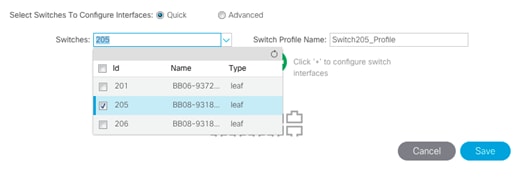
4. Select the A side leaf, (205 in our example).
5. Click ![]() on the right to add switch interfaces.
on the right to add switch interfaces.
6. Configure the various fields as shown in the screenshot below, selecting or entering the following or equivalent values for connecting the Nexus 93180LC-EX leafs to the FlashArray//X A ports for controller 0 and 1:
a. Interface Type: Individual
b. Interfaces: 1/23-24
c. (optional change) Interface Selector Name: Switch206_FlashArrayX-A
d. Link Level Policy: 40Gbps-Link
e. STP Interface Policy: BPDU-FG-Enabled
f. CPD Policy: CDP-Disabled
g. LLDP Policy: LLDP-Disabled
h. L2 Interface Policy: VLAN-Scope-Global
i. Attached Device Type: Bare Metal
j. Domain Name: FlashArrayX-A
k. VLAN Range: 101

7. Click Save.
8. Click Save again to finish the configuring switch interfaces.
9. Click Submit.
10. In the APIC GUI, select Fabric > Access Policies > Quick Start.
11. In the right pane, select Configure and interface, PC and VPC.
12. Click the “+” sign under Configured Switch Interfaces on the left.

13. Select the B side leaf, (206 in our example).

14. Click ![]() on the right to add switch interfaces.
on the right to add switch interfaces.
15. Configure the various fields as shown in the screenshot below, selecting or entering the following or equivalent values for connecting the Nexus 93180LC-EX leafs to the FlashArray//X A ports for controller 0 and 1:
a. Interface Type: Individual
b. Interfaces: 1/23-24
c. (optional change) Interface Selector Name: Switch206_FlashArrayX-B
d. Link Level Policy: 40Gbps-Link
e. STP Interface Policy: BPDU-FG-Enabled
f. CPD Policy: CDP-Disabled
g. LLDP Policy: LLDP-Disabled
h. L2 Interface Policy: VLAN-Scope-Global
i. Attached Device Type: Bare Metal
j. Domain Name: FlashArrayX-B
k. VLAN Range: 102

16. Click Save.
17. Click Save again to finish the configuring switch interfaces.
18. Click Submit.
Configuring Common Tenant for Management Access
This section details the steps to setup in-band management access in the Tenant common. The tenant common This design will allow all the other tenant EPGs to access the common management segment for Core Services VMs such as AD/DNS.

In the APIC GUI, at the top select Tenants > common, and in the left pane, expand Tenant common and Networking to complete the tasks in the following sections.
Create VRF
1. Right-click VRFs and select Create VRF.
2. Enter FSV-Common-IB-Mgmt as the name of the VRF.

3. Click Next.
4. Name the Bridge Domain FSV-Common-IB-Mgmt
5. Change Forwarding to Custom
6. Change L2 Unknown Unicast to Flood.
7. Check Enabled for the Arp Flooding option.

8. Click Finish.
Create Application Profile
1. In the APIC GUI, select Tenants > common.
2. In the left pane, expand Tenant common and Application Profiles.
3. Right-click the Application Profiles and select Create Application Profiles.
4. Enter FSV-Common-IB-Mgmt as the name of the application profile.

5. Click Submit.
Create EPG
1. Expand the FSV-Common-IB-Mgmt Application Profile and right-click the Application EPGs.
2. Select Create Application EPG.
3. Enter FSV-Common-Core-Services as the name of the EPG.
4. Select FSV-Common-IB-Mgmt from the drop-down list for Bridge Domain.
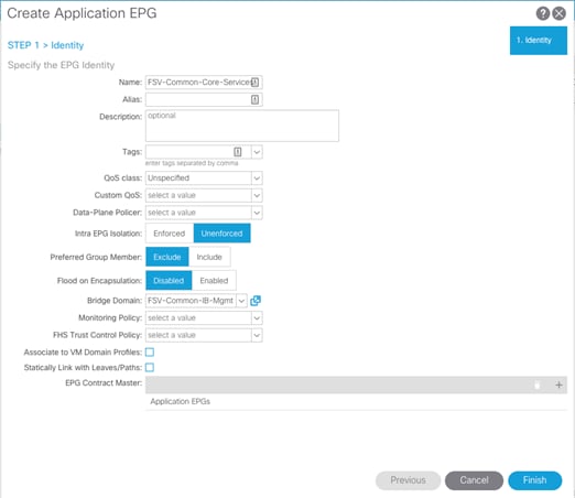
5. Click Finish.
Set Domains for the EPG
1. Expand the newly created EPG and click Domains.
2. Right-click Domains and select Add L2 External Domain Association.
3. Select the Mgmt-Switch as the L2 External Domain Profile.
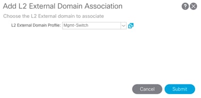
4. Click Submit.
5. Right-click Domains and select Add L2 External Domain Association.
6. Select the FlashStack-UCS as the L2 External Domain Profile.
7. Click Submit.
![]() The Mgmt-Switch and FlashStack-UCS L2 External Domain Profiles were created during the earlier VPC creation process for each of these connections.
The Mgmt-Switch and FlashStack-UCS L2 External Domain Profiles were created during the earlier VPC creation process for each of these connections.
Set Static Ports
1. In the left pane, right-click on Static Ports.
2. Select Deploy Static EPG on PC, VPC, or Interface.
3. For the Path Type, select Virtual Port Channel and from the Path drop-down list, select the VPC for Mgmt-Switch configured earlier.
4. Enter the IB-Mgmt VLAN under Port Encap.
5. Change Deployment Immediacy to Immediate.
6. Set the Mode to Trunk.

7. Click Submit.
Create EPG Subnet
To create a subnet gateway for this Core Services EPG to provide Layer 3 connectivity to Tenant subnets, complete the following steps:
1. In the left pane, right-click Subnets and select Create EPG Subnet.
2. In CIDR notation, put in an IP address and subnet mask to serve as the gateway within the ACI fabric for routing between the Core Services subnet and Tenant subnets.
![]() This IP should be different than the existing IB-MGMT subnet gateway. In this lab validation, 10.1.164.254/24 is the IB-MGMT subnet gateway and is configured externally to the ACI fabric. 10.1.164.1/24 will be used for the EPG subnet gateway. Set the Scope of the subnet to Shared between VRFs.
This IP should be different than the existing IB-MGMT subnet gateway. In this lab validation, 10.1.164.254/24 is the IB-MGMT subnet gateway and is configured externally to the ACI fabric. 10.1.164.1/24 will be used for the EPG subnet gateway. Set the Scope of the subnet to Shared between VRFs.

3. Click Submit to create the Subnet.
Create Provided Contract
1. In the left pane, right-click Contracts and select Add Provided Contract.
2. In the Add Provided Contract window, select Create Contract from the drop-down list.
3. Name the Contract FSV-Allow-Common-Core-Services.
4. Set the scope to Global.
5. Click + to add a Subject to the Contract.
![]() The following steps create a contract to allow all the traffic between various tenants and the common management segment. Customers are encouraged to limit the traffic by setting restrictive filters.
The following steps create a contract to allow all the traffic between various tenants and the common management segment. Customers are encouraged to limit the traffic by setting restrictive filters.
6. Name the subject Allow-All-Traffic.
7. Click + under Filter Chain to add a Filter.
8. From the drop-down Name list, select common/default.
9. In the Create Contract Subject window, click Update to add the Filter Chain to the Contract Subject.

10. Click OK to add the Contract Subject.
![]() The Contract Subject Filter Chain can be modified later.
The Contract Subject Filter Chain can be modified later.

11. Click Submit to finish creating the Contract.

12. Click Submit to finish adding a Provided Contract.
Create Storage Security Filters in Tenant common(optional)
To create Security Filters for iSCSI networks, complete the following steps. This section can also be used to set up other filters necessary to your environment.
1. In the APIC GUI, at the top select Tenants > common.
2. On the left, expand Contracts.
3. Right-click Filters and select Create Filter.
4. Name the filter iSCSI.
5. Click the + sign to add an Entry to the Filter.
6. Name the Entry iSCSI and select EtherType IP.
7. Select the tcp IP Protocol and enter 3260 for From and To under the Destination Port / Range by backspacing over Unspecified and entering the number.
8. Click Update to add the Entry.

9. Click Submit to complete adding the Filter.
![]() By adding these Filters to Tenant common, they can be used from within any Tenant in the ACI Fabric.
By adding these Filters to Tenant common, they can be used from within any Tenant in the ACI Fabric.
Configure FSV-Foundation Tenant
This section details the steps for creating the Foundation Tenant in the ACI Fabric. This tenant will host infrastructure connectivity for the compute (VMware vSphere hosts on UCS nodes) and the storage environments.

To deploy the FSV-Foundation Tenant, complete the following steps.
1. In the APIC GUI, select Tenants > Add Tenant.
2. Name the Tenant as FSV-Foundation.
3. For the VRF Name, enter FSV-Foundation. Keep the check box “Take me to this tenant when I click finish” checked.

4. Click Submit to finish creating the Tenant.
Create Bridge Domain
1. In the left pane, expand Tenant FSV-Foundation and Networking.
2. Right-click Bridge Domains and select Create Bridge Domain.
3. Name the Bridge Domain Foundation-Internal.
4. Select FSV-Foundation from the VRF drop-down list.
5. Select Custom under Forwarding and set Flood for L2 Unknown Unicast.

6. Click Next.
7. Do not change any configuration on the next screen (L3 Configurations). Select Next.
8. No changes are needed for Advanced/Troubleshooting. Click Finish to finish creating Bridge Domain.
Create Application Profile for Infrastructure IB-Management Access
1. In the left pane, expand tenant FSV-Foundation, right-click on Application Profiles and select Create Application Profile.
2. Name the Application Profile as Infra-IB-Mgmt and click Submit to complete adding the Application Profile.
Create EPG for Infra Access
This EPG will be used for vSphere hosts and management virtual machine infrastructure that are in the IB-Mgmt subnet, but that do not provide ACI fabric Core Services. For example, AD server VMs could be placed in the Core Services EPG defined earlier to provide DNS services to tenants in the Fabric. The vCenter VM can be placed in the Infra EPG. It will have access to the Core Services VMs, but will not be reachable from Tenant VMs.
1. In the left pane, expand the Application Profiles and right-click the Infra-IB-Mgmt Application Profile and select Create Application EPG.
2. Name the EPG Infra-IB-Mgmt.
3. From the Bridge Domain drop-down list, select Bridge Domain FSV-Common-IB-Mgmt from Tenant common.

4. Click Finish to complete creating the EPG.
5. Opening up the created EPG in the left menu, right-click Domains and select Add L2 External Domain Association.
6. Select the FlashStack-UCS L2 External Domain Profile and click Submit.
7. In the left menu, right-click Static Ports and select Deploy Static EPG on PC, VPC, or Interface.
8. Select the Virtual Port Channel Path Type, then for Path select the vPC for the UCS Fabric Interconnect A.
9. For Port Encap leave VLAN selected and fill in the UCS IB-Mgmt VLAN ID.
10. Set the Deployment Immediacy to Immediate and click Submit.

11. Repeat steps 7-10 to add the Static Port mapping for the UCS Fabric Interconnect B.
12. In the left menu, right-click Contracts and select Add Consumed Contract.
13. From the drop-down list for the Contract, select FSV-Allow-Common-Core-Services from Tenant common.

14. Click Submit.
This EPG is utilized to provide vSphere hosts as well as the VMs that do not provide Core Services access to the existing in-band management network.
Create Application Profile for Host Connectivity
1. In the left pane, under the Tenant FSV-Foundation, right-click Application Profiles and select Create Application Profile.
2. Name the Profile Host-Connectivity and click Submit to complete adding the Application Profile.
The following EPGs and the corresponding mappings are created under this application profile.
Table 11 EPGs and mappings for Application Profile Host-Connectivity
| EPG Name | Bridge Domain | Domain | Static Port – Compute | Static Port - Storage |
| vMotion | Foundation-Internal | L2 External: FlashStack-UCS | VPC for all UCS FIs VLAN 1110 | N/A |
| Infra-iSCSI-A | Foundation-Internal | L2 External: FlashStack-UCS Physical: FlashArrayX-A | VPC for all UCS FIs VLAN 101 | Interface for FlashArrayX |
| Infra-iSCSI-B | Foundation-Internal | L2 External: UCS Physical: FlashArrayX-B | VPC for all UCS FIs VLAN 102 | Interface for FlashArrayX |
Create EPG for vMotion
1. In the left pane, expand Application Profiles > Host-Connectivity. Right-click Application EPGs and select Create Application EPG.
2. Name the EPG vMotion.
3. From the Bridge Domain drop-down list, select Foundation-Internal.
4. Click Finish to complete creating the EPG.
5. In the left pane, expand the Application EPGs and EPG vMotion.
6. Right-click Domains and select Add L2 External Domain Association.
7. From the drop-down list, select the previously defined FlashStack-UCS L2 External Domain Profile.

8. Click Submit to complete the L2 External Domain Association.
9. Right-click on Static Ports and select Deploy EPG on PC, VPC, or Interface to add the UCS A side VPC for vMotion traffic.
10. In the Deploy Static EPG on PC, VPC, Or Interface Window, select the Virtual Port Channel Path Type.
11. From the drop-down list, select the A side UCS Fabric Port VPC(Switch205-206_UCS6332-16UP-A).
12. Enter the VLAN from Table 11 for vMotion
13. Select Immediate for Deployment Immediacy and for Mode select Trunk.

14. Click Submit to complete adding the Static Path Mapping.
15. Right-click Static Ports and select Deploy EPG on PC, VPC, or Interface to add the UCS B side VPC for vMotion traffic.
16. In the Deploy Static EPG on PC, VPC, Or Interface Window, select the Virtual Port Channel Path Type.
17. From the drop-down list, select the B side UCS Fabric Port VPC (Switch205-206_UCS6332-16UP-B).
18. Enter the VLAN from Table 11 for vMotion {1110}.
19. Select Immediate for Deployment Immediacy and for Mode select Trunk.

20. Click Submit to complete adding the Static Path Mapping.
Create EPG for iSCSI-A
1. Right-click Application EPGs and select Create Application EPG.
2. Name the EPG Infra-iSCSI-A.
3. From the Bridge Domain drop-down list, select Foundation-Internal.
4. Click Finish to complete creating the EPG.
5. In the left pane, expand the Application EPGs and EPG Infra-iSCSI-A.
6. Right-click Domains and select Add L2 External Domain Association.
7. From the down-down list, select the FlashStack-UCS L2 External Domain Profile.

8. Right-click Domains and select Add Physical Domain Association.
9. From the drop-down list, select the FlashArrayX-A Physical Domain Profile.
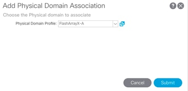
10. Click Submit to complete the Physical Domain Association.
11. Right-click Static Ports and select Deploy EPG on PC, VPC, or Interface to add the UCS Fabric Interconnect A VPC for iSCSI traffic.
12. In the Deploy Static EPG on PC, VPC, Or Interface Window, select the Virtual Port Channel Path Type.
13. From the drop-down list, select the A side UCS Fabric Port VPC (Switch205-206_UCS6332-16UP-A).
14. Enter the UCS VLAN from Table 11 for iSCSI A {101}.
15. Select Immediate for Deployment Immediacy and for Mode select Trunk.

16. Click Submit to complete adding the Static Path Mapping.
17. Optional, repeat these steps to create a Static Path Mapping to UCS Fabric Interconnect B VPC Path.
![]() Enabling the A side iSCSI traffic through Fabric Interconnect B is necessary if later configuring VM-FEX (not covered in this design).
Enabling the A side iSCSI traffic through Fabric Interconnect B is necessary if later configuring VM-FEX (not covered in this design).
18. Right-click on Static Ports and select Deploy EPG on PC, VPC, or Interface to add the FlashArrayX-A side Interfaces for iSCSi traffic.
19. In the Deploy Static EPG on PC, VPC, Or Interface Window, select the Port Path Type.
20. From the drop-down list, select the first path to the port {1/23} to use.
21. Enter VLAN from Table 3 {101} for Port Encap.
22. Select Immediate for Deployment Immediacy and for Mode select Access (802.1P).

23. Click Submit to complete adding the Static Path Mapping.
24. Repeat steps 17-22 for the second port {1/24} going to the FlashArrayX-A.
Create EPG for iSCSI-B
1. Right-click Application EPGs and select Create Application EPG.
2. Name the EPG Infra-iSCSI-B.
3. From the Bridge Domain drop-down list, select Foundation-Internal.
4. Click Finish to complete creating the EPG.
5. In the left pane, expand the Application EPGs and EPG Infra-iSCSI-B.
6. Right-click Domains and select Add L2 External Domain Association.
7. From the down-down list, select the FlashStack-UCS L2 External Domain Profile.

8. Right-click Domains and select Add Physical Domain Association.
9. From the drop-down list, select the FlashArrayX-B Physical Domain Profile.

10. Click Submit to complete the Physical Domain Association.
11. Right-click Static Ports and select Deploy EPG on PC, VPC, or Interface to add the UCS Fabric Interconnect B VPC for iSCSI traffic.
12. In the Deploy Static EPG on PC, VPC, Or Interface Window, select the Virtual Port Channel Path Type.
13. From the drop-down list, select the B side UCS Fabric Port VPC (Switch205-206_UCS6332-16UP-B).
14. Enter the UCS VLAN from Table 11 for iSCSI B {102}
15. Select Immediate for Deployment Immediacy and for Mode select Trunk.
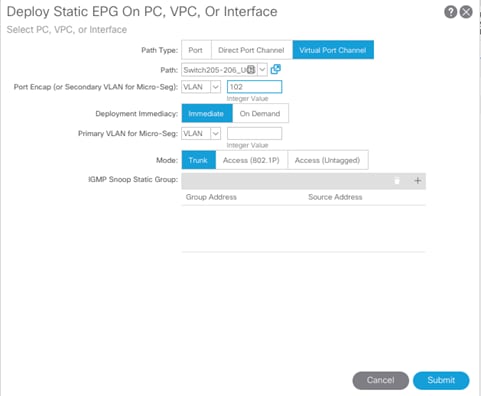
16. Click Submit to complete adding the Static Path Mapping.
17. Optional, repeat these steps to create a Static Path Mapping to UCS Fabric Interconnect B VPC Path.
18. Right-click Static Ports and select Deploy EPG on PC, VPC, or Interface to add the FlashArrayX-B side Interfaces for iSCSi traffic.
19. In the Deploy Static EPG on PC, VPC, Or Interface Window, select the Port Path Type.
20. From the drop-down list, select the first path to the port {1/23} to use.
21. Enter VLAN from Table 3 {102} for Port Encap.
22. Select Immediate for Deployment Immediacy and for Mode select Access (802.1P).

23. Click Submit to complete adding the Static Path Mapping.
24. Repeat steps 20-23 for the second port {1/24} going to the FlashArrayX-B.
Configure EPG Subnets for Host-Connectivity EPGs (Optional)
Creating EPG subnets and gateways for those subnets can help if troubleshooting is required at some point on these networks. The list of EPG Subnets used in this deployment are listed in Table 12.
Table 12 EPGs and Subnets for the Host-Connectivity Application Profile
| EPG Name | Subnet |
| vMotion | 192.168.110.254/24 |
| Infra-iSCSI-A | 192.168.101.254/24 |
| Infra-iSCSI-B | 192.168.102.254/24 |
2. In the Create EPG Subnet window, enter the Subnet from Table 12 as the Default Gateway IP.

3. Click Submit to complete adding the subnet.
4. Repeat the above steps to complete adding the EPGs and subnets in Table 12.
ACI Shared Layer 3 Out Setup
This section provides a detailed procedure for setting the Shared Layer 3 Out in tenant “common” to connect to Nexus 7000 core switches. The configuration utilizes four interfaces between the pair of the ACI leaf switches and the pair of Nexus 7000 switches. The routing protocol being utilized is OSPF. Some highlights of this connectivity are:
· A dedicated bridge domain bd-Common-Outside and associated dedicated VRF vrf-Common-Outside is configured in tenant common for external connectivity.
· The shared Layer 3 Out created in Tenant common “provides” an external connectivity contract that can be “consumed” from any tenant.
· Each of the two Nexus 7000s is connected to each of the two Nexus 9000 leaf switches.
· Sub-interfaces are configured and used for external connectivity.
· The Nexus 7000s are configured to originate and send a default route to the Nexus 9000 leaf switches using OSPF.
· ACI leaf switches advertise tenant subnet back to Nexus 7000 switches
The physical connectivity is shown in Figure 24.
Figure 24 ACI Shared Layer 3 Out Connectivity Details

Nexus 7000 – Sample Configuration
The following configuration is a sample from the virtual device contexts (VDCs) of two Nexus 7004s.
![]() The Nexus 7000 configuration provided below is not complete and is meant to be used only as a reference.
The Nexus 7000 configuration provided below is not complete and is meant to be used only as a reference.
Nexus 7004-1
feature ospf
!
interface Ethernet4/4
description To 9372-1 E1/47
no shutdown
!
interface Ethernet4/4.301
description To 9372-1 E1/47
encapsulation dot1q 301
ip address 10.252.231.2/30
ip ospf network point-to-point
ip ospf mtu-ignore
ip router ospf 10 area 0.0.0.10
no shutdown
!
interface Ethernet4/8
description To 9372-2 E1/47
no shutdown
!
interface Ethernet4/8.302
description To 9372-2 E1/47
encapsulation dot1q 303
ip address 10.252.231.6/30
ip ospf network point-to-point
ip ospf mtu-ignore
ip router ospf 10 area 0.0.0.10
no shutdown
!
interface loopback0
ip address 10.252.255.21/32
ip router ospf 10 area 0.0.0.0
!
router ospf 10
router-id 10.252.255.21
area 0.0.0.10 nssa no-summary no-redistribution default-information-originate
!
Nexus 7004-2
feature ospf
!
interface Ethernet4/4
description To 93180-1 E1/48
no shutdown
!
interface Ethernet4/4.303
description To 93180-1 E1/48
encapsulation dot1q 302
ip address 10.252.231.10/30
ip ospf network point-to-point
ip ospf mtu-ignore
ip router ospf 10 area 0.0.0.10
no shutdown
!
interface Ethernet4/8
description To 93180-2 E1/48
no shutdown
!
interface Ethernet4/8.304
description To 93180-2 E1/48
encapsulation dot1q 304
ip address 10.252.231.14/30
ip ospf network point-to-point
ip ospf mtu-ignore
ip router ospf 10 area 0.0.0.10
no shutdown
!
interface loopback0
ip address 10.252.255.22/32
ip router ospf 10 area 0.0.0.0
!
router ospf 10
router-id 10.252.255.2
area 0.0.0.10 nssa no-summary no-redistribution default-information-originate
!
Configuring ACI Shared Layer 3 Out in Tenant Common
Configure External Routed Domain
1. At the top, select Fabric > Access Policies.
2. In the left pane, expand Physical and External Domains.
3. Right-click External Routed Domains and select Create Layer 3 Domain.
4. Give the domain an appropriate Name, N7K-SharedL3Out in our example.
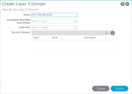
5. From the Associated Attachable Entity Profile drop-down list, select Create Attachable Entity Profile.
6. Give the Profile an appropriate similar name, and click Next.

7. Click Finish to continue without specifying interfaces.
8. Back in the Create Layer 3 Domain window, use the VLAN Pool drop-down list to select Create VLAN Pool.
9. Name the VLAN Pool N7K-SharedL3Out_vlans.
10. Select Static Allocation.
11. Click + to add an Encap Block.
12. In the Create Ranges window, enter the VLAN range as shown in Table 10 (301-304).
13. Select Static Allocation.
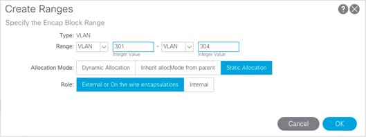
14. Click OK to complete adding the VLAN range.
15. Click Submit to complete creating the VLAN Pool.

16. Click Submit to complete creating the Layer 3 Domain.
Configure Leaf Switch Interfaces
1. In the APIC Advanced GUI, select Fabric > Access Policies > Quick Start.
2. In the right pane, select Configure and interface, PC and VPC.
3. Click the + icon underneath the listing of Configured Switch Interfaces on the left hand side.
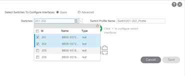
4. Click the drop-down list for Switches and select the two leafs that have been cabled to connect to the Nexus 7Ks.
5. Click ![]() in the right pane to add switch interfaces.
in the right pane to add switch interfaces.
6. Configure the various fields as shown in the screenshot below. In this screen shot, port 1/47 and 1/48 are configured using 10Gbps links to connect up to the Nexus 7K switches.

7. Click Save.
8. Click Save again to finish the configuring switch interfaces
9. Click Submit.
Configure External Routed Networks under Tenant Common
1. At the top, select Tenants > common.
2. In the left pane, expand Tenant common and Networking.
3. Right-click External Routed Networks and select Create Routed Outside.
4. Name the Routed Outside Nexus-7K-Shared.
5. Check the check box next to OSPF.
6. Enter 0.0.0.10 (configured in the Nexus 7000s) as the OSPF Area ID.
7. From the VRF drop-down list, select vrf-Common-Outside.
8. From the External Routed Domain drop-down list, select N7K-SharedL3Out.

9. Under Nodes and Interfaces Protocol Profiles, click + to add a Node Profile.
10. Name the Node Profile Node-201-202.
11. Click + to add a Node.
12. In the select Node and Configure Static Routes window, select Leaf switch 201 from the drop-down list.
13. Provide a Router ID IP address – this address will be configured as the Loopback Address. The address used in this deployment is 10.252.255.1.
14. Click OK to complete selecting the Node.
15. Click + to add another Node.
16. In the select Node window, select Leaf switch 202.
17. Provide a Router ID IP address – this address will be configured as the Loopback Address. The address used in this deployment is 10.252.255.2.
18. Click OK to complete selecting the Node.

19. Click + to create an OSPF Interface Profile.
20. Name the profile Nexus-7K-Int-Prof.

21. Click Next
22. Using the OSPF Policy drop-down list, select Create OSPF Interface Policy.
23. Name the policy ospf-Nexus-7K.
24. Select the Point-to-Point Network Type.
25. Select the MTU ignore Interface Controls.
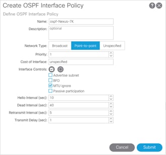
26. Click Submit to complete creating the policy.
27. Click Next.
28. Click + to add a routed sub-interface.
29. Select Routed Sub-Interface under Interfaces.
![]() For adding Routed Sub-interfaces, refer to Figure 6 for Interface, IP and VLAN details
For adding Routed Sub-interfaces, refer to Figure 6 for Interface, IP and VLAN details
30. In the Select Routed Sub-Interface window, for Path, select the interface on Nexus 9372-1 (Node 201) that is connected to Nexus 7004-1.
31. Enter vlan-<interface vlan> (301) for Encap.
32. Enter the IPv4 Address as shown in Table 12 (10.252.231.1/30)
33. Leave the MTU set to inherit.

34. Click OK to complete creating the routed sub-interface.
35. Repeat these steps to all four sub-interfaces. The Routed Sub-Interfaces will be similar to the screenshot below.

36. Click OK to complete creating the Interface Profile.
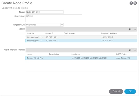
37. Click OK to complete creating the Node Profile.
38. Click NEXT on Create Routed Outside Screen.

39. Click + to create an External EPG Network.
40. Name the External Network Default-Route.
41. Click + to add a Subnet.
42. Enter 0.0.0.0/0 as the IP Address. Select the checkboxes for External Subnets for the External EPG, Shared Route Control Subnet, and Shared Security Import Subnet.

43. Click OK to complete creating the subnet.

44. Click OK to complete creating the external network.
45. Click Finish to complete creating the Routed Outside.
46. In the left pane, Right-click on Contracts and select Create Contract.
47. Name the contract Allow-Shared-L3-Out.
48. Select the Global Scope to allow the contract to be consumed from all tenants.
49. Click + to add a contract subject.
50. Name the subject Allow-Shared-L3-Out.
51. Click + to add a filter.
52. From the drop-down list, select the default from Tenant common.

53. Click Update.
54. Click OK to complete creating the contract subject.
55. Click Submit to complete creating the contract.
56. In the left pane expand Tenant common, Networking, External Routed Networks, Nexus-7K-Shared, and Networks. Select Default-Route.
57. In the right pane under Policy, select Contracts.
58. Click + to add a Provided Contract.
59. Select the common/Allow-Shared-L3-Traffic contract.

60. Click Update.
![]() Tenant EPGs can now consume the Allow-Shared-L3-Traffic contract and route traffic outside fabric. This deployment example shows default filter to allow all traffic. More restrictive contracts can be created for more restrictive access outside the Fabric.
Tenant EPGs can now consume the Allow-Shared-L3-Traffic contract and route traffic outside fabric. This deployment example shows default filter to allow all traffic. More restrictive contracts can be created for more restrictive access outside the Fabric.
FlashArray Initial Configuration
The following information should be gathered to enable the installation and configuration of the FlashArray. An official representative of Pure Storage will help rack and configure the new installation of the FlashArray.
Table 13 FlashArray Setup Information
| Global Array Settings | |
| Array Name (Hostname for Pure Array): |
|
| Virtual IP Address for Management: |
|
| Physical IP Address for Management on Controller 0 (CT0): |
|
| Physical IP Address for Management on Controller 1 (CT1): |
|
| Netmask: |
|
| Gateway IP Address: |
|
| DNS Server IP Address(es): |
|
| DNS Domain Suffix: (Optional) |
|
| NTP Server IP Address or FQDN: |
|
| Email Relay Server (SMTP Gateway IP address or FQDN): (Optional) |
|
| Email Domain Name: |
|
| Alert Email Recipients Address(es): (Optional) |
|
| HTTP Proxy Server and Port (For Pure1): (Optional) |
|
| Time Zone: |
|
When the FlashArray has completed initial configuration, it is important to configure the Cloud Assist phone-home connection in order to provide the best pro-active support experience possible. Furthermore, this will enable the analytics functionalities provided by Pure1.

The Support Connectivity sub-view allows you to view and manage the Purity remote assist, phone home, and log features.
The Remote Assist section displays the remote assist status as "Connected" or "Disconnected." By default, remote assist is disconnected. A connected remote assist status means that a remote assist session has been opened, allowing Pure Storage Support to connect to the array. Disconnect the remote assist session to close the session.
The Phone Home section manages the phone home facility. The phone home facility provides a secure direct link between the array and the Pure Storage Technical Support web site. The link is used to transmit log contents and alert messages to the Pure Storage Support team so that when diagnosis or remedial action is required, complete recent history about array performance and significant events is available.
By default, the phone home facility is enabled. If the phone home facility is enabled to send information automatically, Purity transmits log and alert information directly to Pure Storage Support via a secure network connection. Log contents are transmitted hourly and stored at the support web site, enabling detection of array performance and error rate trends. Alerts are reported immediately when they occur so that timely action can be taken.
Phone home logs can also be sent to Pure Storage Technical support on demand, with options including Today's Logs, Yesterday's Logs, or All Log History.
The Support Logs section allows you to download the Purity log contents of the specified controller to the current administrative workstation. Purity continuously logs a variety of array activities, including performance summaries, hardware and operating status reports, and administrative actions.
Adding an Alert Recipient
The Alerts sub-view is used to manage the list of addresses to which Purity delivers alert notifications, and the attributes of alert message delivery. You can designate up to 19 alert recipients. The Alert Recipients section displays a list of email addresses that are designated to receive Purity alert messages. Up to 20 alert recipients can be designated. The list includes the built-in flasharray-alerts@purestorage.com address, which cannot be deleted.
The Relay Host section displays the hostname or IP address of an SMTP relay host, if one is configured for the array. If you specify a relay host, Purity routes the email messages via the relay (mail forwarding) address rather than sending them directly to the alert recipient addresses.
In the Sender Domain section, the sender domain determines how Purity logs are parsed and treated by Pure Storage Support and Escalations. By default, the sender domain is set to the domain name please-configure.me.
It is crucial that you set the sender domain to the correct domain name. If the array is not a Pure Storage test array, set the sender domain to the actual customer domain name. For example, mycompany.com.
The email address that Purity uses to send alert messages includes the sender domain name and is comprised of the following components:
<Array_Name>-<Controller_Name>@<Sender_Domain_Name>.com
To add an alert recipient, complete the following steps:
1. Select System > Configuration > Alerts.
2. In the Alert Recipients section, click the menu icon and select Add Alert Recipient. The Create Alert User dialog box appears.
3. In the email field, enter the email address of the alert recipient.
4. Click Save.

Configuring the Domain Name System (DNS) Server IP Addresses
To configure the DNS server IP addresses, complete the following steps:
1. Select System > Configuration > Networking.
2. In the DNS section, hover over the domain name and click the pencil icon. The Edit DNS dialog box appears.
3. Complete the following fields:
a. Domain: Specify the domain suffix to be appended by the array when doing DNS lookups.
b. DNS#: Specify up to three DNS server IP addresses for Purity to use to resolve hostnames to IP addresses. Enter one IP address in each DNS# field. Purity queries the DNS servers in the order that the IP addresses are listed.
4. Click Save.
iSCSI Interface Configuration
The iSCSI traffic is carried on two VLANs, A (101) and B (102) that are configured in our example with the following values:
Table 14 iSCSI A FlashArray//X Interface Configuration Settings
| Device | Interface | IP | Netmask | Gateway (Optional) |
| FlashArray//X70 Controller 1 | CT0.ETH8 | 192.168.101.41 | 255.255.255.0 | 192.168.101.254 |
| FlashArray//X70 Controller 2 | CT1.ETH8 | 192.168.101.42 | 255.255.255.0 | 192.168.102.254 |
Table 15 iSCSI B FlashArray//X Interface Configuration Settings
| Device | Interface | IP | Netmask | Gateway (Optional) |
| FlashArray//X70 Controller 1 | CT0.ETH9 | 192.168.102.41 | 255.255.255.0 | 192.168.101.254 |
| FlashArray//X70 Controller 2 | CT1.ETH9 | 192.168.102.42 | 255.255.255.0 | 192.168.102.254 |
To configure iSCSI interfaces for environments deploying iSCSI boot LUNs and/or datastores, complete the following steps:
1. Select System > Configuration > Networking.
2. Click the ellipsis (…) on the far right side of ct0.eth0 and select edit.
3. Select the Enabled check mark box within the Edit Network Interface dialogue window, enter the Address and Netmask from Table 14 above, and set the MTU to 9000 to enable jumbo frames.

4. Click Save.
5. Repeat these steps for ct0.eth9, ct1.eth8, and ct1.eth9 using values from Table 14 and Table 15.
Directory Service Sub-View
The Directory Service sub-view manages the integration of FlashArrays with an existing directory service. When the Directory Service sub-view is configured and enabled, the FlashArray leverages a directory service to perform user account and permission level searches.
![]() Configuring the directory services is optional.
Configuring the directory services is optional.

The FlashArray is delivered with a single local user, named pureuser, with array-wide (Array Admin) permissions.
To support multiple FlashArray users, integrate the array with a directory service, such as Microsoft Active Directory or OpenLDAP.
Role-based access control is achieved by configuring groups in the directory that correspond to the following permission groups (roles) on the array:
· Read Only Group. Read Only users have read-only privileges to run commands that convey the state of the array. Read Only uses cannot alter the state of the array.
· Storage Admin Group. Storage Admin users have all the privileges of Read Only users, plus the ability to run commands related to storage operations, such as administering volumes, hosts, and host groups. Storage Admin users cannot perform operations that deal with global and system configurations.
· Array Admin Group. Array Admin users have all the privileges of Storage Admin users, plus the ability to perform array-wide changes. In other words, Array Admin users can perform all FlashArray operations.
When a user connects to the FlashArray with a username other than pureuser, the array confirms the user's identity from the directory service. The response from the directory service includes the user's group, which Purity maps to a role on the array, granting access accordingly.
To configure the directory service settings, complete the following steps:
1. Select System > Configuration > Directory Service.
2. Configure the Directory Service fields:
a. Enabled: Select the check box to leverage the directory service to perform user account and permission level searches.
b. URI: Enter the comma-separated list of up to 30 URIs of the directory servers. The URI must include a URL scheme (ldap, or ldaps for LDAP over SSL), the hostname, and the domain. You can optionally specify a port. For example, ldap://ad.company.com configures the directory service with the hostname "ad" in the domain "company.com" while specifying the unencrypted LDAP protocol.
c. Base DN: Enter the base distinguished name (DN) of the directory service. The Base DN is built from the domain and should consist only of domain components (DCs). For example, for ldap://ad.storage.company.com, the Base DN would be: “DC=storage,DC=company,DC=com”
d. Bind User: Username used to bind to and query the directory. For Active Directory, enter the username - often referred to as sAMAccountName or User Logon Name - of the account that is used to perform directory lookups. The username cannot contain the characters " [ ] : ; | = + * ? < > / \, and cannot exceed 20 characters in length. For OpenLDAP, enter the full DN of the user. For example, "CN=John,OU=Users,DC=example,DC=com".
e. Bind Password: Enter the password for the bind user account.
f. Group Base: Enter the organizational unit (OU) to the configured groups in the directory tree. The Group Base consists of OUs that, when combined with the base DN attribute and the configured group CNs, complete the full Distinguished Name of each groups. The group base should specify "OU=" for each OU and multiple OUs should be separated by commas. The order of OUs should get larger in scope from left to right. In the following example, SANManagers contains the sub-organizational unit PureGroups: "OU=PureGroups,OU=SANManagers".
g. Array Admin Group: Common Name (CN) of the directory service group containing administrators with full privileges to manage the FlashArray. Array Admin Group administrators have the same privileges as pureuser. The name should be the Common Name of the group without the "CN=" specifier. If the configured groups are not in the same OU, also specify the OU. For example, "pureadmins,OU=PureStorage", where pureadmins is the common name of the directory service group.
h. Storage Admin Group: Common Name (CN) of the configured directory service group containing administrators with storage related privileges on the FlashArray. The name should be the Common Name of the group without the "CN=" specifier. If the configured groups are not in the same OU, also specify the OU. For example, "pureusers,OU=PureStorage", where pureusers is the common name of the directory service group.
i. Read Only Group: Common Name (CN) of the configured directory service group containing users with read-only privileges on the FlashArray. The name should be the Common Name of the group without the "CN=" specifier. If the configured groups are not in the same OU, also specify the OU. For example, "purereadonly,OU=PureStorage", where purereadonly is the common name of the directory service group.
j. Check Peer: Select the check box to validate the authenticity of the directory servers using the CA Certificate. If you enable Check Peer, you must provide a CA Certificate.
k. CA Certificate: Enter the certificate of the issuing certificate authority. Only one certificate can be configured at a time, so the same certificate authority should be the issuer of all directory server certificates. The certificate must be PEM formatted (Base64 encoded) and include the "-----BEGIN CERTIFICATE-----" and "-----END CERTIFICATE-----" lines. The certificate cannot exceed 3000 characters in total length.
3. Click Save.
4. Click Test to test the configuration settings. The LDAP Test Results pop-up window appears. Green squares represent successful checks. Red squares represent failed checks.
SSL Certificate Sub-View
Purity creates a self-signed certificate and private key when you start the system for the first time. The SSL Certificate sub-view allows you to view and change certificate attributes, create a new self-signed certificate, construct certificate signing requests, import certificates and private keys, and export certificates.

Creating a self-signed certificate replaces the current certificate. When you create a self-signed certificate, include any attribute changes, specify the validity period of the new certificate, and optionally generate a new private key.

When you create the self-signed certificate, you can generate a private key and specify a different key size. If you do not generate a private key, the new certificate uses the existing key.
You can change the validity period of the new self-signed certificate. By default, self-signed certificates are valid for 3650 days.
CA-Signed Certificate
Certificate authorities (CA) are third party entities outside the organization that issue certificates. To obtain a CA certificate, you must first construct a certificate signing request (CSR) on the array.
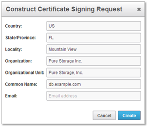
The CSR represents a block of encrypted data specific to your organization. You can change the certificate attributes when you construct the CSR; otherwise, Purity will reuse the attributes of the current certificate (self-signed or imported) to construct the new one. Note that the certificate attribute changes will only be visible after you import the signed certificate from the CA.
Send the CSR to a certificate authority for signing. The certificate authority returns the SSL certificate for you to import. Verify that the signed certificate is PEM formatted (Base64 encoded), includes the "-----BEGIN CERTIFICATE-----" and "-----END CERTIFICATE-----" lines, and does not exceed 3000 characters in total length. When you import the certificate, also import the intermediate certificate if it is not bundled with the CA certificate.

If the certificate is signed with the CSR that was constructed on the current array and you did not change the private key, you do not need to import the key. However, if the CSR was not constructed on the current array or if the private key has changed since you constructed the CSR, you must import the private key. If the private key is encrypted, also specify the passphrase.
This section provides detailed instructions for the configuration of the Cisco UCS 6332-16UP Fabric Interconnects used in this FlashStack solution. As with the Nexus Switches covered beforehand, some changes may be appropriate for a customer’s environment, but care should be taken when stepping outside of these instructions as it may lead to an improper configuration.
Figure 25 Cisco UCS Configuration Workflow
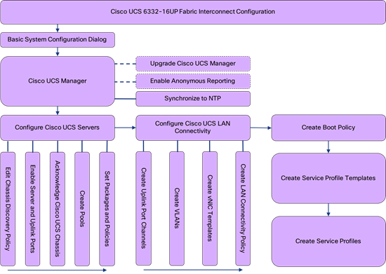
Physical Connectivity
Physical cabling should be completed by following the diagram and table references in section FlashStack Cabling.
Cisco UCS Base Configuration
The initial configuration dialogue for the Cisco UCS 6332-16UP Fabric Interconnects will be provide the primary information to the first fabric interconnect, with the second taking on most settings after joining the cluster.
To start on the configuration of the Fabric Interconnect A, connect to the console of the fabric interconnect and step through the Basic System Configuration Dialogue:
---- Basic System Configuration Dialog ----
This setup utility will guide you through the basic configuration of
the system. Only minimal configuration including IP connectivity to
the Fabric interconnect and its clustering mode is performed through these steps.
Type Ctrl-C at any time to abort configuration and reboot system.
To back track or make modifications to already entered values,
complete input till end of section and answer no when prompted
to apply configuration.
Enter the configuration method. (console/gui) ? console
Enter the setup mode; setup newly or restore from backup. (setup/restore) ? setup
You have chosen to setup a new Fabric interconnect. Continue? (y/n): y
Enforce strong password? (y/n) [y]: <Enter>
Enter the password for "admin": ********
Confirm the password for "admin": ********
Is this Fabric interconnect part of a cluster(select 'no' for standalone)? (yes/no) [n]: y
Enter the switch fabric (A/B) []: A
Enter the system name: <<var_ucs_6332_clustername>>
Physical Switch Mgmt0 IP address : <<var_ucsa_mgmt_ip>>
Physical Switch Mgmt0 IPv4 netmask : <<var_oob_mgmt_mask>>
IPv4 address of the default gateway : <<var_oob_gateway>>
Cluster IPv4 address : <<var_ucs_mgmt_vip>>
Configure the DNS Server IP address? (yes/no) [n]: y
DNS IP address : <<var_nameserver_ntp>>
Configure the default domain name? (yes/no) [n]: y
Default domain name : <<var_dns_domain_name>>
Join centralized management environment (UCS Central)? (yes/no) [n]: <Enter>
Following configurations will be applied:
Switch Fabric=A
System Name=bb08-6332
Enforced Strong Password=yes
Physical Switch Mgmt0 IP Address=192.168.164.51
Physical Switch Mgmt0 IP Netmask=255.255.255.0
Default Gateway=192.168.164.254
Ipv6 value=0
DNS Server=10.1.164.9
Domain Name=flashstack.cisco.com
Cluster Enabled=yes
Cluster IP Address=192.168.164.50
NOTE: Cluster IP will be configured only after both Fabric Interconnects are initialized.
UCSM will be functional only after peer FI is configured in clustering mode.
Apply and save the configuration (select 'no' if you want to re-enter)? (yes/no): yes
Applying configuration. Please wait.
Configuration file - Ok
Continue the configuration on the console of the Fabric Interconnect B:
Enter the configuration method. (console/gui) [console] ?
Installer has detected the presence of a peer Fabric interconnect. This Fabric interconnect will be added to the cluster. Continue (y/n) ? y
Enter the admin password of the peer Fabric interconnect:
Connecting to peer Fabric interconnect... done
Retrieving config from peer Fabric interconnect... done
Peer Fabric interconnect Mgmt0 IPv4 Address: 192.168.164.51
Peer Fabric interconnect Mgmt0 IPv4 Netmask: 255.255.255.0
Cluster IPv4 address : 192.168.164.50
Peer FI is IPv4 Cluster enabled. Please Provide Local Fabric Interconnect Mgmt0 IPv4 Address
Physical Switch Mgmt0 IP address : 192.168.164.52
Apply and save the configuration (select 'no' if you want to re-enter)? (yes/no): yes
Applying configuration. Please wait.
Cisco UCS Manager Setup
Log in to Cisco UCS Manager
To log in to the Cisco Unified Computing System environment, complete the following steps:
1. Open a web browser and navigate to the Cisco UCS fabric interconnect cluster address.
2. Click the Launch UCS Manager link within the opening page.
3. If prompted to accept security certificates, accept as necessary.
4. When the Cisco UCS Manager login is prompted, enter admin as the user name and enter the administrative password.
5. Click Login to log in to Cisco UCS Manager.
Upgrade Cisco UCS Manager Software to Version 3.2(3d)
This document assumes the use of Cisco UCS 3.2(3d). To upgrade the Cisco UCS Manager software and the Cisco UCS Fabric Interconnect software to version 3.2(3d), refer to Cisco UCS Manager Install and Upgrade Guides.
Anonymous Reporting
During the first connection to the Cisco UCS Manager GUI, a pop-up window will appear to allow for the configuration of Anonymous Reporting to Cisco on use to help with future development. To create anonymous reporting, complete the following step:
1. In the Anonymous Reporting window, select whether to send anonymous data to Cisco for improving future products, and provide the appropriate SMTP server gateway information.

2. If there is a desire to enable or disable Anonymous Reporting at a later date, it can be found within Cisco UCS Manager under: Admin -> Communication Management -> Call Home, which has a tab on the far right for Anonymous Reporting.
Synchronize Cisco UCS to NTP
To synchronize the Cisco UCS environment to the NTP server, complete the following steps:
1. In Cisco UCS Manager, click the Admin tab in the navigation pane.
2. Select Timezone Management and click Timezone.

3. In the Properties pane, select the appropriate time zone in the Timezone menu.
4. Click Save Changes and then click OK.
5. Click Add NTP Server.
6. Enter <<var_oob_ntp>> and click OK.
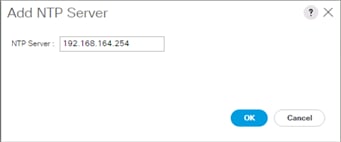
7. Click OK.
Configure Cisco UCS Servers
Edit Chassis Discovery Policy
Setting the discovery policy simplifies the addition of B-Series Cisco UCS chassis. To modify the chassis discovery policy, complete the following steps:
1. In Cisco UCS Manager, click the Equipment tab in the navigation pane and select Policies in the list on the left under the drop-down list.
2. Under Global Policies, set the Chassis/FEX Discovery Policy to match the number of uplink ports that are cabled between the chassis or FEX (fabric extenders) and the fabric interconnects.
3. Set the Link Grouping Preference to Port Channel.

4. Leave other settings alone or change if appropriate to your environment.
5. Click Save Changes.
6. Click OK.
Enable Server and Uplink Ports
To enable server and uplink ports, complete the following steps:
1. In Cisco UCS Manager, click the Equipment tab in the navigation pane.
2. Select Equipment > Fabric Interconnects > Fabric Interconnect A (primary) > Fixed Module.
3. Expand Ethernet Ports.
4. Select the ports that are connected to the chassis, right-click them, and select “Configure as Server Port.”

5. Click Yes to confirm server ports and click OK.
6. Verify that the ports connected to the chassis are now configured as server ports.
7. Select ports 39 and 40 that are connected to the Cisco Nexus switches, right-click them, and select Configure as Uplink Port.
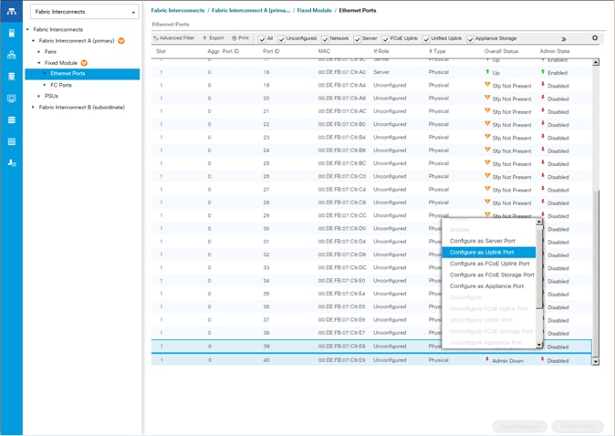
![]() The last 6 ports of the UCS 6332 and UCS 6332-16UP FIs will only work with optical based QSFP transceivers and AOC cables, so they can be better utilized as uplinks to upstream resources that might be optical only.
The last 6 ports of the UCS 6332 and UCS 6332-16UP FIs will only work with optical based QSFP transceivers and AOC cables, so they can be better utilized as uplinks to upstream resources that might be optical only.
8. Click Yes to confirm uplink ports and click OK.
9. Select Equipment > Fabric Interconnects > Fabric Interconnect B (subordinate) > Fixed Module.
10. Expand Ethernet Ports.
11. Select the ports that are connected to the chassis, right-click them and select Configure as Server Port.
12. Click Yes to confirm server ports and click OK.
13. Select ports 39 and 40 that are connected to the Cisco Nexus switches, right-click them, and select Configure as Uplink Port.
14. Click Yes to confirm the uplink ports and click OK.
Acknowledge Cisco UCS Chassis
To acknowledge all Cisco UCS chassis, complete the following steps:
1. In Cisco UCS Manager, click the Equipment tab in the navigation pane.
2. Expand Chassis and select each chassis that is listed.
3. Right-click each chassis and select Acknowledge Chassis.

4. Click Yes and then click OK to complete acknowledging the chassis.
Create Pools
Create MAC Address Pools
To configure the necessary MAC address pools for the Cisco UCS environment, complete the following steps:
1. In Cisco UCS Manager, click the LAN tab in the navigation pane.
2. Select Pools > root.
![]() In this procedure, two MAC address pools are created, one for each switching fabric.
In this procedure, two MAC address pools are created, one for each switching fabric.
3. Right-click MAC Pools under the root organization.
4. Select Create MAC Pool to create the MAC address pool.
5. Enter MAC_Pool_A as the name of the MAC pool.
6. Optional: Enter a description for the MAC pool.
7. Select Sequential as the option for Assignment Order.

8. Click Next.
9. Click Add.
10. Specify a starting MAC address.
![]() For Cisco UCS deployments, the recommendation is to place 0A in the next-to-last octet of the starting MAC address to identify all of the MAC addresses as fabric A addresses. In our example, we have carried forward the of also embedding the extra building, floor and Cisco UCS domain number information giving us 00:25:B5:91:1A:00 as our first MAC address.
For Cisco UCS deployments, the recommendation is to place 0A in the next-to-last octet of the starting MAC address to identify all of the MAC addresses as fabric A addresses. In our example, we have carried forward the of also embedding the extra building, floor and Cisco UCS domain number information giving us 00:25:B5:91:1A:00 as our first MAC address.
11. Specify a size for the MAC address pool that is sufficient to support the available blade or server resources.

12. Click OK.
13. Click Finish.
14. In the confirmation message, click OK.
15. Right-click MAC Pools under the root organization.
16. Select Create MAC Pool to create the MAC address pool.
17. Enter MAC_Pool_B as the name of the MAC pool.
18. Optional: Enter a description for the MAC pool.

19. Click Next.
20. Click Add.
21. Specify a starting MAC address.
![]() For Cisco UCS deployments, it is recommended to place 0B in the next to last octet of the starting MAC address to identify all the MAC addresses in this pool as fabric B addresses. In our example, we embedded the extra building, floor and Cisco UCS domain number information giving us 00:25:B5:91:1B:00 as our first MAC address.
For Cisco UCS deployments, it is recommended to place 0B in the next to last octet of the starting MAC address to identify all the MAC addresses in this pool as fabric B addresses. In our example, we embedded the extra building, floor and Cisco UCS domain number information giving us 00:25:B5:91:1B:00 as our first MAC address.
22. Specify a size for the MAC address pool that is sufficient to support the available blade or server resources.

23. Click OK.
24. Click Finish.
25. In the confirmation message, click OK.
Create UUID Suffix Pool
To configure the necessary universally unique identifier (UUID) suffix pool for the Cisco UCS environment, complete the following steps:
1. In Cisco UCS Manager, click the Servers tab in the navigation pane.
2. Select Pools > root.
3. Right-click UUID Suffix Pools.
4. Select Create UUID Suffix Pool.
5. Enter UUID_Pool as the name of the UUID suffix pool.

6. Optional: Enter a description for the UUID suffix pool.
7. Keep the prefix at the derived option.
8. Select Sequential for the Assignment Order.
9. Click Next.
10. Click Add to add a block of UUIDs.
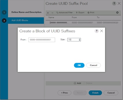
11. Keep the From: field at the default setting.
12. Specify a size for the UUID block that is sufficient to support the available blade or server resources.
13. Click OK.
14. Click Finish.
15. Click OK.
Create Server Pool
To configure the necessary server pool for the Cisco UCS environment, complete the following steps:
![]() Consider creating unique server pools to achieve the granularity that is required in your environment.
Consider creating unique server pools to achieve the granularity that is required in your environment.
1. In Cisco UCS Manager, click the Servers tab in the navigation pane.
2. Select Pools > root.
3. Right-click Server Pools.
4. Select Create Server Pool.
5. Enter Infra_Pool as the name of the server pool.

6. Optional: Enter a description for the server pool.
7. Click Next.
8. Select two (or more) servers to be used for the VMware management cluster and click >> to add them to the Infra_Pool server pool.

9. Click Finish.
10. Click OK.
Create IQN Pools for iSCSI Boot
To configure the necessary IQN pools for the Cisco UCS environment, complete the following steps:
1. In Cisco UCS Manager, click SAN on the left.
2. Select Pools > root.
3. Right-click IQN Pools.
4. Select Create IQN Suffix Pool to create the IQN pool.
5. Enter IQN-Pool for the name of the IQN pool
6. Optional: Enter a description for the IQN pool
7. Enter iqn.1992-08.com.cisco as the prefix.
8. Select Sequential for Assignment Order
9. Click Next.
10. Click Add.
11. Enter ucs-host as the suffix.
12. If multiple Cisco UCS domains are being used, a more specific IQN suffix may need to be used.
13. Enter 1 in the From field.
14. Specify the size of the IQN block sufficient to support the available server resources.
15. Click OK.

16. Click Finish.
Add a Block of IP Addresses for KVM Access
To create a block of IP addresses for in band server Keyboard, Video, Mouse (KVM) access in the Cisco UCS environment, complete the following steps:
1. In Cisco UCS Manager, click the LAN tab in the navigation pane.
2. Select Pools > root > IP Pools.
3. Right-click IP Pool ext-mgmt and select Create Block of IPv4 Addresses.

4. Enter the starting IP address of the block and the number of IP addresses required, and the subnet and gateway information.
5. Click OK to create the block of IPs.
6. Click OK.
Create IP Pools for iSCSI Boot
To configure the necessary IP pools iSCSI boot for the Cisco UCS environment, complete the following steps:
1. In Cisco UCS Manager, click LAN on the left.
2. Select Pools > root.
3. Right-click IP Pools.
4. Select Create IP Pool.
5. Enter iSCSI-Pool-A as the name of IP pool.
6. Optional: Enter a description for the IP pool.
7. Select Sequential for the assignment order.
8. Click Next.
9. Click Add to add a block of IP address.
10. In the From field, enter the beginning of the range to assign as iSCSI IP addresses.
11. Set the size to enough addresses to accommodate the servers.
12. (Optional) Specify a Default Gateway if one was created for the Infra-iSCSI-A EPG Subnet.

13. Click OK.
14. Click Next.
15. Click Finish.
16. Right-click IP Pools.
17. Select Create IP Pool.
18. Enter iSCSI-Pool-B as the name of IP pool.
19. Optional: Enter a description for the IP pool.
20. Select Sequential for the assignment order.
21. Click Next.
22. Click Add to add a block of IP address.
23. In the From field, enter the beginning of the range to assign as iSCSI IP addresses.
24. Set the size to enough addresses to accommodate the servers.
25. (Optional) Specify a Default Gateway if one was created for the Infra-iSCSI-B EPG Subnet.

26. Click OK.
27. Click Next.
28. Click Finish.
Set Packages and Policies
Create Host Firmware Package
Firmware management policies allow the administrator to select the corresponding packages for a given server configuration. These policies often include packages for adapter, BIOS, board controller, FC adapters, host bus adapter (HBA) option ROM, and storage controller properties.
To create a firmware management policy for a given server configuration in the Cisco UCS environment, complete the following steps:
1. In Cisco UCS Manager, click the Servers tab in the navigation pane.
2. Select Policies > root.
3. Expand Host Firmware Packages.
4. Select default.
5. In the Actions pane, select Modify Package Versions.
6. Select the version 3.2(3d)B for the Blade Package, and optionally set version 3.2(3d)C for the Rack Package.
7. Leave Excluded Components with only Local Disk selected.
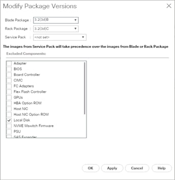
8. Click OK to modify the host firmware package.
Create Server Pool Qualification Policy (Optional)
To create an optional server pool qualification policy for the Cisco UCS environment, complete the following steps:
![]() This example creates a policy for Cisco UCS B200 M5 servers for a server pool.
This example creates a policy for Cisco UCS B200 M5 servers for a server pool.
1. In Cisco UCS Manager, click the Servers tab in the navigation pane.
2. Select Policies > root.
3. Right-click Server Pool Policy Qualifications.
4. Select Create Server Pool Policy Qualification.
5. Name the policy UCS-B200M5.
6. Select Create Server PID Qualifications.
7. Select UCS-B200-M5 from the PID drop-down list.
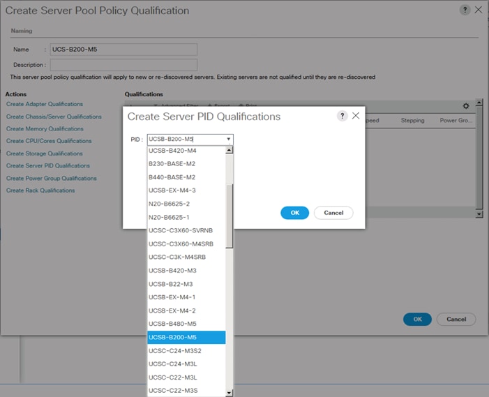
8. Click OK.
9. Optionally select additional qualifications to refine server selection parameters for the server pool.
10. Click OK to create the policy then OK for the confirmation.
Download Cisco Custom Image for ESXi 6.5 U1
The VMware Cisco Custom Image will need to be downloaded for use during installation by manual access to the UCS KVM vMedia, or through a vMedia Policy covered in the subsection that follows these steps. To download the Cisco Custom Image, complete the following steps:
1. Click the following link: VMware vSphere Hypervisor Cisco Custom Image (ESXi) 6.5 U1.
![]() You will need a user id and password on vmware.com to download this software.
You will need a user id and password on vmware.com to download this software.
2. Download the .iso file.
Create vMedia Policy for VMware ESXi 6.5 U1 Install Boot (optional if manually attaching ISO through KVM)
A separate HTTP web server is required to automate the availability of the ESXi image to each Service Profile on first power on. The creation of this web server is not covered in this document, but can be any existing web server capable of serving files via HTTP that are accessible on the OOB network that the ESXi image can be placed upon.
Place the Cisco Custom Image VMware ESXi 6.5 U1 ISO on the HTTP server and complete the following steps to create a vMedia Policy:
1. In Cisco UCS Manager, select Servers on the left.
2. Select Policies > root.
3. Right-click vMedia Policies.
4. Select Create vMedia Policy.
5. Name the policy ESXi-6.5U1-HTTP.
6. Enter “Mounts ISO for ESXi 6.5 U1” in the Description field.
7. Click Add.
8. Name the mount ESXi-6.5U1-HTTP.
9. Select the CDD Device Type.
10. Select the HTTP Protocol.
11. Enter the IP Address of the web server.
![]() Since DNS server IPs were not entered into the KVM IP earlier, it is necessary to enter the IP of the web server instead of the hostname.
Since DNS server IPs were not entered into the KVM IP earlier, it is necessary to enter the IP of the web server instead of the hostname.
12. Leave “None” selected for Image Name Variable.
13. Enter Vmware-ESXi-6.5.0-5969303-Custom-Cisco-6.5.1.2.iso as the Remote File name.
14. Enter the web server path to the ISO file in the Remote Path field.

15. Click OK to create the vMedia Mount.
16. Click OK then OK again to complete creating the vMedia Policy.
![]() For new servers added to the Cisco UCS environment the vMedia service profile template can be used to install the ESXi host. On first boot the host will boot into the ESXi installer. After ESXi is installed, the vMedia will not be referenced as long as the boot disk is accessible.
For new servers added to the Cisco UCS environment the vMedia service profile template can be used to install the ESXi host. On first boot the host will boot into the ESXi installer. After ESXi is installed, the vMedia will not be referenced as long as the boot disk is accessible.
Create Server BIOS Policy
The settings for the BIOS policy used are based on the specifications for virtualized workloads covered in this white paper: https://www.cisco.com/c/dam/en/us/products/collateral/servers-unified-computing/ucs-b-series-blade-servers/whitepaper_c11-740098.pdf Additional info on these settings, as well as other workload specifications can be found in the white paper. To create a server BIOS policy for the Cisco UCS environment, complete the following steps:
1. In Cisco UCS Manager, click Servers on the left.
2. Select Policies > root.
3. Right-click BIOS Policies.
4. Select Create BIOS Policy.
5. Enter VM-Host as the BIOS policy name.

6. Select and right-click the newly created BIOS Policy.
7. Within the Main tab of the Policy:
a. Change CDN Control to enabled.
b. Change the Quiet Boot setting to disabled.

8. Click the Advanced tab, leaving the Processor tab selected within the Advanced tab.
9. Set the following within the Processor tab:
a. Package C State Limit -> C0 C1 State
b. Processor C State -> Disabled
c. Processor O State -> Disabled
d. Processor O1E State -> Disabled
e. Processor O3 State -> Disabled
f. Processor O6 State -> Disabled
g. Processor O7 State -> Disabled
h. Power Technology -> Custom

10. Click Save Changes.
11. Click OK.
Update the Default Maintenance Policy
To update the default Maintenance Policy, complete the following steps:
1. In Cisco UCS Manager, click the Servers tab in the navigation pane.
2. Select Policies > root.
3. Select Maintenance Policies > default.
4. Change the Reboot Policy to User Ack.
5. (Optional: Click “On Next Boot” to delegate maintenance windows to server owners).

6. Click Save Changes.
7. Click OK to accept the change.
Create Local Disk Configuration Policy (Optional)
A local disk configuration for the Cisco UCS environment is necessary if the servers in the environment do not have a local disk.
![]() This policy should not be used on servers that contain local disks.
This policy should not be used on servers that contain local disks.
To create a local disk configuration policy, complete the following steps:
1. In Cisco UCS Manager, click the Servers tab in the navigation pane.
2. Select Policies > root.
3. Right-click Local Disk Config Policies.
4. Select Create Local Disk Configuration Policy.
5. Enter SAN-Boot as the local disk configuration policy name.
6. Change the mode to No Local Storage.
7. Click OK to create the local disk configuration policy.

8. Click OK.
Create Power Control Policy
To create a power control policy for the Cisco UCS environment, complete the following steps:
1. In Cisco UCS Manager, click the Servers tab in the navigation pane.
2. Select Policies > root.
3. Right-click Power Control Policies.
4. Select Create Power Control Policy.
5. Enter No-Power-Cap as the power control policy name.
6. Change the power capping setting to No Cap.

7. Click OK to create the power control policy.
8. Click OK.
Create Network Control Policy for Cisco Discovery Protocol
To create a network control policy that enables Cisco Discovery Protocol (CDP) on virtual network ports, complete the following steps:
1. In Cisco UCS Manager, click the LAN tab in the navigation pane.
2. Select Policies > root.
3. Right-click Network Control Policies.
4. Select Create Network Control Policy.
5. Enter Enable_CDP as the policy name.
6. For CDP, select the Enabled option.
7. Click OK to create the network control policy.

8. Click OK.
Configure UCS LAN Connectivity
Create Uplink Port Channels
To configure the necessary port channels out of the Cisco UCS environment, complete the following steps:
1. In Cisco UCS Manager, click the LAN tab in the navigation pane.
![]() In this procedure, two port channels are created: one from fabric A to both Cisco Nexus switches and one from fabric B to both Cisco Nexus switches.
In this procedure, two port channels are created: one from fabric A to both Cisco Nexus switches and one from fabric B to both Cisco Nexus switches.
2. Under LAN > LAN Cloud, expand the Fabric A tree.
3. Right-click Port Channels.
4. Select Create Port Channel.
5. Enter a unique ID for the port channel, (5 in our example to correspond with the upstream ACI fabric vPC the port channel is connecting to, but this alignment is optional).
![]() The upstream vPC can be determined by connecting to one of the management interface of the Nexus 93180LC-EX and running the show port-channel summary command to look for the interface configured to connect to this UCS port channel, or by looking at the APIC GUI within Fabric->Inventory->Pod 1->[Nexus Leaf]->Interfaces->VPC Interfaces.
The upstream vPC can be determined by connecting to one of the management interface of the Nexus 93180LC-EX and running the show port-channel summary command to look for the interface configured to connect to this UCS port channel, or by looking at the APIC GUI within Fabric->Inventory->Pod 1->[Nexus Leaf]->Interfaces->VPC Interfaces.
6. With 5 selected, enter vPC-5-ACI as the name of the port channel.

7. Click Next.
8. Select the following ports to be added to the port channel:
· Slot ID 1 and port 39
· Slot ID 1 and port 40

9. Click >> to add the ports to the port channel.
10. Click Finish to create the port channel.
11. Click OK.
12. In the navigation pane, under LAN > LAN Cloud, expand the fabric B tree.
13. Right-click Port Channels.
14. Select Create Port Channel.
15. Enter a unique ID for the port channel, (4 in our example to correspond with the upstream ACI fabric vPC, but this alignment is purely optional).
16. With 4 selected, enter vPC-4-ACI as the name of the port channel.

17. Click Next.
18. Select the following ports to be added to the port channel:
· Slot ID 1 and port 39
· Slot ID 1 and port 40

19. Click >> to add the ports to the port channel.
20. Click Finish to create the port channel.
21. Click OK.
Create VLANs
To configure the necessary virtual local area networks (VLANs) for the Cisco UCS environment, complete the following steps:
1. In Cisco UCS Manager, click the LAN tab in the navigation pane.
2. Select LAN > LAN Cloud.
3. Right-click VLANs.
4. Select Create VLANs.
5. Enter Native-VLAN as the name of the VLAN to be used as the native VLAN.
6. Keep the Common/Global option selected for the scope of the VLAN.
7. Enter the native VLAN ID.
8. Keep the Sharing Type as None.

9. Click OK and then click OK again.
10. Expand the list of VLANs in the navigation pane, right-click the newly created Native-VLAN and select Set as Native VLAN.
11. Click Yes and then click OK.
12. Right-click VLANs.
13. Select Create VLANs
14. Enter IB-Mgmt as the name of the VLAN to be used for UCS management traffic.
15. Keep the Common/Global option selected for the scope of the VLAN.
16. Enter the In-Band management VLAN ID.
17. Keep the Sharing Type as None.

18. Click OK and then click OK again.
19. Right-click VLANs.
20. Select Create VLANs.
21. Enter vMotion as the name of the VLAN to be used for vMotion.
22. Keep the Common/Global option selected for the scope of the VLAN.
23. Enter the vMotion VLAN ID.
24. Keep the Sharing Type as None.

1. Click OK and then click OK again.
2. Right-click VLANs.
3. Select Create VLANs.
4. Enter iSCSI-A-VLAN as the name of the VLAN to be used for iSCSI-A.
5. Keep the Common/Global option selected for the scope of the VLAN.
6. Enter the iSCSI-A VLAN ID.
7. Keep the Sharing Type as None.

25. Click OK and then click OK again.
26. Right-click VLANs.
27. Select Create VLANs.
28. Enter iSCSI-B-VLAN as the name of the VLAN to be used for iSCSI-B.
29. Keep the Common/Global option selected for the scope of the VLAN.
30. Enter the iSCSI-B VLAN ID.
31. Keep the Sharing Type as None.

32. Click OK and then click OK again.
33. Right-click VLANs.
34. Select Create VLANs.
35. Enter VM-App- as the prefix of the VLANs to be used for VM Traffic.
36. Keep the Common/Global option selected for the scope of the VLAN.
37. Enter the VM-Traffic VLAN ID range.
38. Keep the Sharing Type as None.

39. Click OK and then click OK again.
Create vNIC Templates
To create the multiple virtual network interface card (vNIC) templates for the Cisco UCS environment, complete the steps in the following sections.
Create Management vNICs
For the vNIC_Mgmt_A Template, complete the following steps:
1. In Cisco UCS Manager, click the LAN tab in the navigation pane.
2. Select Policies > root.
3. Right-click vNIC Templates.
4. Select Create vNIC Template.
5. Enter vNIC_Mgmt_A as the vNIC template name.
6. Keep Fabric A selected.
7. Optional: select the Enable Failover checkbox.
![]() Selecting Failover can improve link failover time by handling it at the hardware level, and can guard against any potential for NIC failure not being detected by the virtual switch.
Selecting Failover can improve link failover time by handling it at the hardware level, and can guard against any potential for NIC failure not being detected by the virtual switch.
8. Select Primary Template for the Redundancy Type.
9. Leave Peer Redundancy Template as <not set>
![]() Redundancy Type and specification of Redundancy Template are configuration options to later allow changes to the Primary Template to automatically adjust onto the Secondary Template.
Redundancy Type and specification of Redundancy Template are configuration options to later allow changes to the Primary Template to automatically adjust onto the Secondary Template.
10. Under Target, make sure that the VM checkbox is not selected.
11. Select Updating Template as the Template Type.
12. Under VLANs, select the checkboxes for IB-Mgmt and Native-VLAN VLANs.

13. Set Native-VLAN as the native VLAN.
14. Leave vNIC Name selected for the CDN Source.
15. Leave 1500 for the MTU.
16. In the MAC Pool list, select MAC_Pool_A.
17. In the Network Control Policy list, select Enable_CDP.
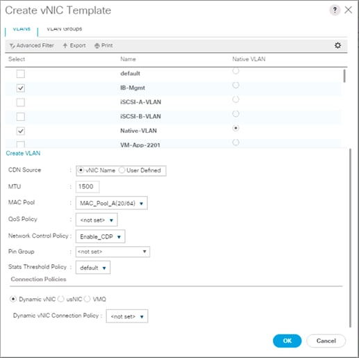
18. Click OK to create the vNIC template.
19. Click OK.
For the vNIC_Mgmt_B Template, complete the following steps:
1. In the navigation pane, select the LAN tab.
2. Select Policies > root.
3. Right-click vNIC Templates.
4. Select Create vNIC Template
5. Enter vNIC_Mgmt_B as the vNIC template name.
6. Select Fabric B.
7. Select Secondary Template for Redundancy Type.
8. For the Peer Redundancy Template pulldown, select vNIC_Mgmt_A.
![]() With Peer Redundancy Template selected, Failover specification, Template Type, VLANs, CDN Source, MTU, and Network Control Policy are all pulled from the Primary Template.
With Peer Redundancy Template selected, Failover specification, Template Type, VLANs, CDN Source, MTU, and Network Control Policy are all pulled from the Primary Template.
9. Under Target, make sure the VM checkbox is not selected.

10. In the MAC Pool list, select MAC_Pool_B.

11. Click OK to create the vNIC template.
12. Click OK.
Create vMotion vNICs
For the vNIC_vMotion_A Template, complete the following steps:
1. In Cisco UCS Manager, click the LAN tab in the navigation pane.
2. Select Policies > root.
3. Right-click vNIC Templates.
4. Select Create vNIC Template.
5. Enter vNIC_vMotion_A as the vNIC template name.
6. Keep Fabric A selected.
7. Optional: select the Enable Failover checkbox.
8. Select Primary Template for the Redundancy Type.
9. Leave Peer Redundancy Template as <not set>
10. Under Target, make sure that the VM checkbox is not selected.
11. Select Updating Template as the Template Type.
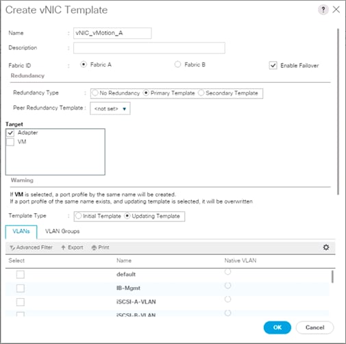
12. Under VLANs, select the checkboxes for vMotion and Native-VLAN.
13. Set Native-VLAN as the native VLAN.
14. For MTU, enter 9000.
15. In the MAC Pool list, select MAC_Pool_A.
16. In the Network Control Policy list, select Enable_CDP.
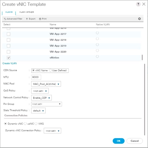
17. Click OK to create the vNIC template.
18. Click OK.
For the vNIC_vMotion_B Template, complete the following steps:
1. In the navigation pane, select the LAN tab.
2. Select Policies > root.
3. Right-click vNIC Templates.
4. Select Create vNIC Template
5. Enter vNIC_vMotion_B as the vNIC template name.
6. Select Fabric B.
7. Select Secondary Template for Redundancy Type.
8. For the Peer Redundancy Template pulldown, select vNIC_vMotion_A.
![]() With Peer Redundancy Template selected, MAC Pool will be the main configuration option left for this vNIC template.
With Peer Redundancy Template selected, MAC Pool will be the main configuration option left for this vNIC template.
9. Under Target, make sure the VM checkbox is not selected.

10. In the MAC Pool list, select MAC_Pool_B.

11. Click OK to create the vNIC template.
12. Click OK.
Create Application vNICs
For the vNIC_App_A Template, complete the following steps:
1. In Cisco UCS Manager, click the LAN tab in the navigation pane.
2. Select Policies > root.
3. Right-click vNIC Templates.
4. Select Create vNIC Template.
5. Enter vNIC_App_A as the vNIC template name.
6. Keep Fabric A selected.
7. Optional: select the Enable Failover checkbox.
8. Select Primary Template for the Redundancy Type.
9. Leave Peer Redundancy Template as <not set>
10. Under Target, make sure that the VM checkbox is not selected.
11. Select Updating Template as the Template Type.
12. Set default as the native VLAN.

13. Under VLANs, select the checkboxes for full range of application VLANs (VM-App-[2201-2220]) that will be delivered to the ESXi hosts.
![]() If a limited number of application/tenant VLANs will be used, selections can be limited to those immediately needed, with others added later as this is an updating template.
If a limited number of application/tenant VLANs will be used, selections can be limited to those immediately needed, with others added later as this is an updating template.
14. Do not set a Native VLAN.
15. For MTU, enter 9000.
16. In the MAC Pool list, select MAC_Pool_A.
17. In the Network Control Policy list, select Enable_CDP.

18. Click OK to create the vNIC template.
19. Click OK.
For the vNIC_App_B Templates, complete the following steps:
1. In the navigation pane, select the LAN tab.
2. Select Policies > root.
3. Right-click vNIC Templates.
4. Select Create vNIC Template
5. Enter vNIC_App_B as the vNIC template name.
6. Select Fabric B.
7. Select Secondary Template for Redundancy Type.
8. For the Peer Redundancy Template pulldown, select vNIC_App_A.
![]() With Peer Redundancy Template selected, MAC Pool will be the main configuration option left for this vNIC template.
With Peer Redundancy Template selected, MAC Pool will be the main configuration option left for this vNIC template.
9. Under Target, make sure the VM checkbox is not selected.

10. In the MAC Pool list, select MAC_Pool_B.

11. Click OK to create the vNIC template.
12. Click OK.
Create iSCSI vNICs
In Cisco UCS Manager, click the LAN tab in the navigation pane.
1. Select Policies > root.
2. Right-click vNIC Templates.
3. Select Create vNIC Template.
4. Enter vNIC_iSCSI_A as the vNIC template name.
5. Keep Fabric A selected.
6. Do not select the Enable Failover checkbox.
7. Keep the No Redundancy options selected for the Redundancy Type.
8. Under Target, make sure that the Adapter checkbox is selected.
9. Select Updating Template as the Template Type.
10. Under VLANs, select iSCSI-A-VLAN as the only VLAN and set it as the Native VLAN.

11. For MTU, enter 9000.
12. In the MAC Pool list, select MAC_Pool_A.
13. In the Network Control Policy list, select Enable_CDP.

14. Click OK to create the vNIC template.
15. Click OK.
For the vNIC_iSCSI_B Template, complete the following steps:
1. In the navigation pane, select the LAN tab.
2. Select Policies > root.
3. Right-click vNIC Templates.
4. Select Create vNIC Template.
5. Enter vNIC_iSCSI_B as the vNIC template name.
6. Keep Fabric B selected.
7. Do not select the Enable Failover checkbox.
8. Keep the No Redundancy options selected for the Redundancy Type.
9. Under Target, make sure that the Adapter checkbox is selected.
10. Select Updating Template as the Template Type.
11. Under VLANs, select iSCSI-B-VLAN as the only VLAN and set it as the Native VLAN.

12. For MTU, enter 9000.
13. In the MAC Pool list, select MAC_Pool_B.
14. In the Network Control Policy list, select Enable_CDP.

15. Click OK to create the vNIC template.
16. Click OK.
Set Jumbo Frames in Cisco UCS Fabric
To configure jumbo frames and enable quality of service in the Cisco UCS fabric, complete the following steps:
1. In Cisco UCS Manager, click the LAN tab in the navigation pane.
2. Select LAN > LAN Cloud > QoS System Class.
3. In the right pane, click the General tab.
4. On the Best Effort row, enter 9216 in the box under the MTU column.
5. Click Save Changes in the bottom of the window.

6. Click OK
Create LAN Connectivity Policy
To configure the necessary iSCSI Infrastructure LAN Connectivity Policy, complete the following steps:
1. In Cisco UCS Manager, click LAN.
2. Select LAN > Policies > root.
3. Right-click LAN Connectivity Policies.
4. Select Create LAN Connectivity Policy.
5. Enter iSCSI-LAN-Policy as the name of the policy.
6. Click the upper Add button to add a vNIC.
7. In the Create vNIC dialog box, enter 00-Mgmt-A as the name of the vNIC.
8. Select the Use vNIC Template checkbox.
9. In the vNIC Template list, select 00-Mgmt-A.
10. In the Adapter Policy list, select VMWare.
11. Click OK to add this vNIC to the policy.

12. Click Add to add another vNIC to the policy.
13. In the Create vNIC box, enter 01-Mgmt-B as the name of the vNIC.
14. Select the Use vNIC Template checkbox.
15. In the vNIC Template list, select 01-Mgmt-B.
16. In the Adapter Policy list, select VMWare.

17. Click OK to add the vNIC to the policy.
18. Click the upper Add button to add a vNIC.
19. In the Create vNIC dialog box, enter 02-vMotion-A as the name of the vNIC.
20. Select the Use vNIC Template checkbox.
21. In the vNIC Template list, select vNIC_vMotion_A.
22. In the Adapter Policy list, select VMWare.
23. Click OK to add this vNIC to the policy.

24. Click the upper Add button to add a vNIC to the policy.
25. In the Create vNIC dialog box, enter 03-vMotion-B as the name of the vNIC.
26. Select the Use vNIC Template checkbox.
27. In the vNIC Template list, select vNIC_vMotion_B.
28. In the Adapter Policy list, select VMWare.

29. Click OK to add this vNIC to the policy.
30. Click the upper Add button to add a vNIC.
31. In the Create vNIC dialog box, enter 04-App-A as the name of the vNIC.
32. Select the Use vNIC Template checkbox.
33. In the vNIC Template list, select vNIC_App_A.
34. In the Adapter Policy list, select VMWare.
35. Click OK to add this vNIC to the policy.

36. Click the upper Add button to add a vNIC to the policy.
37. In the Create vNIC dialog box, enter 05-App-B as the name of the vNIC.
38. Select the Use vNIC Template checkbox.
39. In the vNIC Template list, select vNIC_App_B.
40. In the Adapter Policy list, select VMWare.

41. Click OK to add this vNIC to the policy.
42. Click the upper Add button to add a vNIC.
43. In the Create vNIC dialog box, enter 06-iSCSI-A as the name of the vNIC.
44. Select the Use vNIC Template checkbox.
45. In the vNIC Template list, select iSCSI-Template-A.
46. In the Adapter Policy list, select VMWare.

47. Click OK to add this vNIC to the policy.
48. Click the upper Add button to add a vNIC to the policy.
49. In the Create vNIC dialog box, enter 07-iSCSI-B as the name of the vNIC.
50. Select the Use vNIC Template checkbox.
51. In the vNIC Template list, select iSCSI-Template-B.
52. In the Adapter Policy list, select VMWare.

53. Click OK to add this vNIC to the policy.
54. Expand the Add iSCSI vNICs.

55. Select Add in the Add iSCSI vNICs section.
56. Set the name to iSCSI—A-vNIC.
57. Select the 06-iSCSI-A as Overlay vNIC.
58. Set the VLAN to iSCSI-A-VLAN (native).
59. Set the iSCSI Adapter Policy to default
60. Leave the MAC Address set to None.

61. Click OK.
62. Select Add in the Add iSCSI vNICs section.
63. Set the name to iSCSI-B-vNIC.
64. Select the 07-iSCSI-A as Overlay vNIC.
65. Set the VLAN to iSCSI-B-VLAN.
66. Set the iSCSI Adapter Policy to default.
67. Leave the MAC Address set to None.

68. Click OK, then click OK again to create the LAN Connectivity Policy.
Create Boot Policy
This procedure creates a boot policy for iSCSI boot off of the FlashArray//X pointing to the two iSCSI interfaces on controller 1 (ct0.eth8 and ct0.eth9) and the two iSCSI interfaces on controller 2 (ct1.eth8 and ct1.eth9).
To create a boot policy for the Cisco UCS environment, complete the following steps:
1. In Cisco UCS Manager, click Servers on the left.
2. Select Policies > root.
3. Right-click Boot Policies.
4. Select Create Boot Policy.
5. Enter Boot-iSCSI-X-A as the name of the boot policy.
6. Optional: Enter a description for the boot policy.
![]() Do not select the Reboot on Boot Order Change checkbox.
Do not select the Reboot on Boot Order Change checkbox.
7. Keep the Reboot on Boot Order Change option cleared.
8. Expand the Local Devices drop-down menu and select Add Remote CD/DVD.
9. Expand the iSCSI vNICs drop-down menu and select Add iSCSI Boot.
10. In the Add iSCSI Boot dialog box, enter iSCSI-A-vNIC.
11. Click OK.
12. Select Add iSCSI Boot.
13. In the Add iSCSI Boot dialog box, enter iSCSI-B-vNIC.
14. Click OK.
15. Expand CIMC Mounted Media and select Add CIMC Mounted CD/DVD.

16. Click OK to create the policy.
Create Service Profile Template
In this procedure, one service profile template for Infrastructure ESXi hosts is created for iSCSI A boot.
To create the service profile template, complete the following steps:
1. In Cisco UCS Manager, click the Servers tab in the navigation pane.
2. Select Service Profile Templates > root.
3. Right-click root.
4. Select Create Service Profile Template to open the Create Service Profile Template wizard.
5. Enter VM-Host-iSCSI-A as the name of the service profile template. This service profile template is configured to boot from FlashArray//X controller 1 on fabric A.
6. Select the “Updating Template” option.
7. Under UUID, select UUID_Pool as the UUID pool.

8. Click Next.
Configure Storage Provisioning
1. If you have servers with no physical disks, click the Local Disk Configuration Policy tab and select the SAN-Boot Local Storage Policy. Otherwise, select the default Local Storage Policy.

2. Click Next.
Configure Networking Options
To configure the network options, complete the following steps:
1. Keep the default setting for Dynamic vNIC Connection Policy.
2. Select the “Use Connectivity Policy” option to configure the LAN connectivity.
3. Select iSCSI-LAN-Policy from the LAN Connectivity Policy pull-down.
4. Select IQN_Pool in Initiator Name Assignment.

5. Click Next.
Configure Storage Options
1. Select the No vHBA option for the “How would you like to configure SAN connectivity?” field.
2. Click Next.
Configure Zoning Options
1. Leave Zoning configuration unspecified, and click Next.
Configure vNIC/HBA Placement
1. In the “Select Placement” list, leave the placement policy as “Let System Perform Placement”.
2. Click Next.
Configure vMedia Policy
1. Do not select a vMedia Policy.
2. Click Next.
Configure Server Boot Order
1. Select Boot-iSCSI-X-A for Boot Policy.
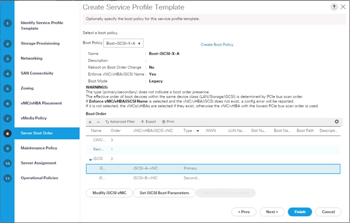
2. In the Boor order, select iSCSI-A-vNIC.
3. Click Set iSCSI Boot Parameters button.
4. In the Set iSCSI Boot Parameters pop-up, leave Authentication Profile to <not set> unless you have independently created one appropriate to your environment.
5. Leave the “Initiator Name Assignment” dialog box <not set> to use the single Service Profile Initiator Name defined in the previous steps.
6. Set iSCSI_IP_Pool_A as the “Initiator IP address Policy”.
7. Select iSCSI Static Target Interface option.
8. Click Add.
9. Enter the iSCSI Target Name for ct0.eth8. To get the iSCSI target name of the FlashArray//X, login to the Pure Web console and navigate to SYSTEM -> Connections -> Target Ports.

10. Find the targets from connecting to the controller via ssh using the pureuser login and run the pureport list command:
pureuser@cspg-rtp-2> pureport list
Name WWN Portal IQN Failover
CT0.ETH8 - 192.168.101.41:3260 iqn.2010-06.com.purestorage:flasharray.491a50eccb3c035 -
CT0.ETH9 - 192.168.102.41:3260 iqn.2010-06.com.purestorage:flasharray.491a50eccb3c035 -
CT0.FC0 52:4A:93:76:87:FF:47:00 - - -
CT0.FC1 52:4A:93:76:87:FF:47:01 - - -
CT0.FC2 52:4A:93:76:87:FF:47:02 - - -
CT0.FC3 52:4A:93:76:87:FF:47:03 - - -
CT0.FC6 52:4A:93:76:87:FF:47:06 - - -
CT0.FC7 52:4A:93:76:87:FF:47:07 - - -
CT1.ETH8 - 192.168.101.42:3260 iqn.2010-06.com.purestorage:flasharray.491a50eccb3c035 -
CT1.ETH9 - 192.168.102.42:3260 iqn.2010-06.com.purestorage:flasharray.491a50eccb3c035 -
CT1.FC0 52:4A:93:76:87:FF:47:10 - - -
CT1.FC1 52:4A:93:76:87:FF:47:11 - - -
CT1.FC2 52:4A:93:76:87:FF:47:12 - - -
CT1.FC3 52:4A:93:76:87:FF:47:13 - - -
CT1.FC6 52:4A:93:76:87:FF:47:16 - - -
CT1.FC7 52:4A:93:76:87:FF:47:17 - - -
11. Leave the Port set to 3260, Authentication Profile as <not set>, provide the appropriate IPv4 Address configured to ct0.eth8, and set the LUN ID to 1.

12. Click OK to add the iSCSI Static Target.
13. Click Add again to add another iSCSI Target for the iSCSI-A-vNIC that will associate with ct1.eth8.
14. Enter the same iSCSI Target Name, leave the Port set to 3260, the Authentication Profile as <not set>, provide the appropriate IPv4 Address configured to ct1.eth8, and set the LUN ID to 1.

15. Click OK to add the iSCSI Static Target.

16. Click OK to set the iSCSI-A-vNIC ISCSI Boot Parameters.
17. In the Boor order, select iSCSI-B-vNIC.
18. Click Set iSCSI Boot Parameters button.
19. In the Set iSCSI Boot Parameters pop-up, leave Authentication Profile to <not set> unless you have independently created one appropriate to your environment.
20. Leave the “Initiator Name Assignment” dialog box <not set> to use the single Service Profile Initiator Name defined in the previous steps.
21. Set iSCSI_IP_Pool_B as the “Initiator IP address Policy.”
22. Select iSCSI Static Target Interface option.
23. Click Add.
24. Enter the same iSCSI Target Name, leave the Port set to 3260, the Authentication Profile as <not set>, provide the appropriate IPv4 Address configured to ct0.eth9, and set the LUN ID to 1.
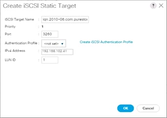
25. Click OK to add the iSCSI Static Target.
26. Click Add again to add another iSCSI Target for the iSCSI-B-vNIC that will associate with ct1.eth9.
27. Enter the same iSCSI Target Name, leave the Port set to 3260, the Authentication Profile as <not set>, provide the appropriate IPv4 Address configured to ct1.eth9, and set the LUN ID to 1.
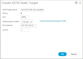
28. Click OK to add the iSCSI Static Target.
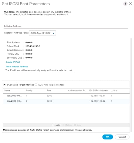
29. Click OK to set the iSCSI-B-vNIC ISCSI Boot Parameters.
30. Click Next to continue to the next section.
Configure Maintenance Policy
1. Change the Maintenance Policy to default.

2. Click Next.
Configure Server Assignment(optional)
To configure server assignment, complete the following steps:
1. In the Pool Assignment list, select Infra_Pool.
2. Optional: Select a Server Pool Qualification policy.
3. Select Down as the power state to be applied when the profile is associated with the server.
4. Optional: Select “UCS-B200M5” for the Server Pool Qualification.
![]() Firmware Management at the bottom of the page can be left alone as it will use default from the Host Firmware list.
Firmware Management at the bottom of the page can be left alone as it will use default from the Host Firmware list.

5. Click Next.
Configure Operational Policies
To configure the operational policies, complete the following steps:
1. In the BIOS Policy list, select VM-Host.
2. Expand Power Control Policy Configuration and select No-Power-Cap in the Power Control Policy list.

3. Click Finish to create the service profile template.
4. Click OK in the confirmation message.
Create vMedia Service Profile Template
If the optional ESXi 6.5 U1 vMedia Policy is being used, a clone of the created service profile template will be made to reference this vMedia Policy. The clone of the service profile template will have the vMedia Policy configured for it, and service profiles created from it, will be unbound and re-associated to the original service profile template after ESXi installation. To create a clone of the VM-Host-iSCSI-A service profile template, and associate the vMedia Policy to it, complete the following steps:
1. Connect to UCS Manager, click Servers on the left.
2. Select Service Profile Templates > root > Service Template VM-Host-iSCSI-A.
3. Right-click Service Template VM-Host-iSCSI-A and select Create a Clone.
4. Name the clone VM-Host-iSCSi-A-vM and click OK.
5. Select Service Template VM-Host-iSCSi-A-vM.
6. In the right pane, select the vMedia Policy tab.
7. Under Actions, select Modify vMedia Policy.
8. Using the drop-down list, select the ESXi-6.5U1-HTTP vMedia Policy.
9. Click OK then OK again to complete modifying the Service Profile Template.
Create Service Profiles
To create service profiles from the service profile template, complete the following steps:
1. Connect to the UCS 6332-16UP Fabric Interconnect UCS Manager, click the Servers tab in the navigation pane.
2. Select Service Profile Templates > root > Service Template VM-Host-iSCSI-A-vM.
3. Right-click VM-Host-iSCSI-A-vM and select Create Service Profiles from Template.
4. Enter VM-Host-iSCSI-0 as the service profile prefix.
5. Leave 1 as “Name Suffix Starting Number.”
6. Leave 2 as the “Number of Instances.”
7. Click OK to create the service profiles.

8. Click OK in the confirmation message to provision two FlashStack Service Profiles.
![]() When VMware ESXi 6.5 U1 has been installed on the hosts, the host Service Profiles can be unbound from the VM-Host-iSCSI-A-vM and rebound to the VM-Host-iSCSI-A Service Profile Template to remove the vMedia mapping from the host, to prevent issues at boot time if the HTTP source for the ESXi ISO is somehow not available.
When VMware ESXi 6.5 U1 has been installed on the hosts, the host Service Profiles can be unbound from the VM-Host-iSCSI-A-vM and rebound to the VM-Host-iSCSI-A Service Profile Template to remove the vMedia mapping from the host, to prevent issues at boot time if the HTTP source for the ESXi ISO is somehow not available.
The Pure Storage FlashArray//X is accessible to the FlashStack, but no storage has been deployed at this point. The storage to be deployed will include:
· ESXi iSCSI Boot LUNs
· VMFS Datastores
The iSCSI Boot LUNs will need to be setup from the Pure Storage Web Portal as they are assigned directly to the host object with a LUNID of 1, and the VMFS datastores will be directly provisioned from the vSphere Web Client after the Pure Storage vSphere Web Client Plugin has later on been registered with the vCenter, these are assigned to the host group object and are visible to all hosts within the host group.
Figure 26 FlashArray//X Storage Deployment Workflow

Host Port Identification
iSCSI Boot LUNs will be mapped by the filer using the assigned Initiator Name to the provisioned service profiles. This information can be found within the service profile, within the iSCSI vNICs tab:

Host Registration
For Host registration, complete the following steps:
1. Host entries can be made from the Pure Storage Web Portal from the STORAGE tab, by selecting the + box next to Hosts appearing in the left side column.

2. After clicking the Create Host option, a pop-up will appear to create an individual host entry on the FlashArray.

3. To create more than one host entry, click the Create Multiple… option, filling in the Name, Start Number, Count, and Number of Digits, with a “#” appearing in the name where an iterating number will appear.

4. Click Create to add the hosts.
5. For each host created, select the host from within the STORAGE tab, and click the Host Ports tab within the individual host view. From the Host Ports tab select the gear icon pull-down and select Configure iSCSI IQNs.

6. A pop-up will appear for Configure iSCSI IQNs for Host <host being configured>. Within this pop-up, enter the IQN Initiator Name found within the service profile for the host being configured.

7. After adding the IQN, click Confirm to add the Host Ports. Repeat these steps for each host created.
Private Volumes for each ESXi Host
To create private volumes for each ESXi host, complete the following steps:
1. Volumes can be provisioned from the Pure Storage Web Portal from the STORAGE tab, by clicking the + box next to Volumes appearing in the left side column.

2. A pop-up will appear to create a volume on the FlashArray.

3. To create more than one volume, click the Create Multiple… option, filling in the Name, Provisioned Size, Staring Number, Count, and Number of Digits, with a “#” appearing in the name where an iterating number will appear.

4. Click Create to provision the volumes to be used as iSCSI boot LUNs.
5. Go back to the Hosts section under the STORAGE tab. Click one of the hosts and select the gear icon drop-down list within the Connected Volumes tab within that host.

6. From the drop-down list, select Connect Volumes, and a pop-up will appear.

7. Select the volume that has been provisioned for the host, click the + next to the volume and select Confirm to proceed.
8. Repeat the steps for connecting volumes for each of the host/volume pairs configured.
Host Groups
The Host entries allow for the individual boot LUNs to associate to each ESXi host, but the shared volumes to use as VM datastores need Host Groups to have those volumes shared amongst multiple hosts.
To create a Host Group in the Pure Storage Web Portal, complete the following steps:
1. Select the STORAGE tab and click the + box next to Hosts appearing in the left side column.

2. Select the Create Host Group option and provide a name for the Host Group to be used by the ESXi cluster.
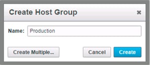
3. With Hosts still selected within the STORAGE tab, click the gear icon pull-down within the Hosts tab of the Host Group created, and select Add Hosts.
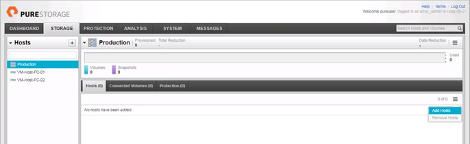
4. Select the check box next to each host, and click Confirm to add them to the Host Group.
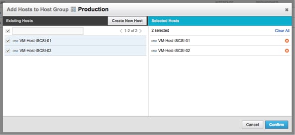
Infrastructure Datastore
Tenant VM datastores can be created through the Pure vSphere Web Plugin, but if vCenter is to be installed within the FlashStack, a base infrastructure datastore will need to be created through the Pure Web Console before installation of the vCenter Appliance.
To create a datastore and associate it to the hosts that will be created, perform the following steps:
1. Select the + icon next to the Volumes section of the Storage tab to create an Infrastructure volume.
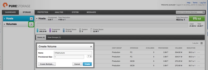
2. Specify an appropriate Name, set the Provisioned Size desired, and click Create.
3. Select the newly created volume from within the Volumes section and click the menu selection bar on the far right within the Connected Host Groups sub-tab.

4. Click the Connect Host Groups option from the drop-down list.

5. Select the Host Group previously created and select Confirm to add the volume to the Host Group.
ESXi Installation
This section provides detailed instructions to install VMware ESXi 6.5 U1 in a FlashStack environment. After the procedures are completed, the iSCSI SAN booted ESXi hosts will be configured.
Figure 27 vSphere Deployment Workflow

Several methods exist for installing ESXi in a VMware environment. These procedures focus on how to use the built-in keyboard, video, mouse (KVM) console and virtual media features in Cisco UCS Manager to map remote installation media to individual servers and connect to their boot logical unit numbers (LUNs).
Download Cisco Custom Image for ESXi 6.5 U1
The VMware Cisco Custom Image will be needed for use during installation by manual access to the UCS KVM vMedia, or through a vMedia Policy covered in a previous subsection. If the Cisco Custom Image was not downloaded during the vMedia Policy setup, download it now by completing the following steps:
1. Click the following link: VMware vSphere Hypervisor Cisco Custom Image (ESXi) 6.5 U1.
2. You will need a user id and password on vmware.com to download this software.
3. Download the .iso file.
Log in to Cisco UCS 6332-16UP Fabric Interconnect
The IP KVM enables the administrator to begin the installation of the operating system (OS) through remote media. It is necessary to log in to the UCS environment to run the IP KVM.
To log in to the Cisco UCS environment, complete the following steps:
1. Open a web browser to https:// <<var_ucs_mgmt_vip>>
2. Select the Launch UCS Manager Section in the HTML section to pull up the UCSM HTML5 GUI.
3. Enter admin for the Username, and provide the password used during setup.
4. Within the UCSM select Servers -> Service Profiles, and pick the first host provisioned as VM-Host-iSCSI-01.
5. Click the KVM Console option within Actions, and accept the KVM server certificate in the new window or browser tab that is spawned for the KVM session.
6. Click the link within the new window or browser tab to load the KVM client application.
Set Up VMware ESXi Installation
![]() Skip this step if you are using vMedia policies. ISO file will already be connected to KVM.
Skip this step if you are using vMedia policies. ISO file will already be connected to KVM.
To prepare the server for the OS installation, complete the following steps on each ESXi host:
1. In the KVM window, click Virtual Media icon ![]() in the upper right of the screen.
in the upper right of the screen.
2. Click Activate Virtual Devices.
3. Click Virtual Media again and select Map CD/DVD.
4. Browse to the ESXi installer ISO image file and click Open.
5. Click Map Device.
6. Click the KVM tab to monitor the server boot.
7. Boot the server by selecting Boot Server and clicking OK, then click OK again.
Install ESXi
To install VMware ESXi to the iSCSI bootable LUN of the hosts, complete the following steps on each host:
1. On reboot, the machine detects the presence of the ESXi installation media. Select the ESXi installer from the boot menu that is displayed.
2. After the installer is finished loading, press Enter to continue with the installation.
3. Read and accept the end-user license agreement (EULA). Press F11 to accept and continue.
4. Select the LUN that was previously set up as the installation disk for ESXi and press Enter to continue with the installation.
5. Select the appropriate keyboard layout and press Enter.
6. Enter and confirm the root password and press Enter.
7. The installer issues a warning that the selected disk will be repartitioned. Press F11 to continue with the installation.
8. After the installation is complete, if using locally mapped Virtual Media, click the Virtual Media tab and clear the P mark next to the ESXi installation media. Click Yes.
![]() The ESXi installation image must be unmapped to make sure that the server reboots into ESXi and not into the installer. If using a vMedia Policy, this will be unnecessary as the vMedia will appear after the installed OS.
The ESXi installation image must be unmapped to make sure that the server reboots into ESXi and not into the installer. If using a vMedia Policy, this will be unnecessary as the vMedia will appear after the installed OS.
9. From the KVM window, press Enter to reboot the server.
10. Repeat these steps for each additional host provisioned.
Set Up Management Networking for ESXi Hosts
Adding a management network for each VMware host is necessary for managing the host. To add a management network for the VMware hosts, complete the following steps on each ESXi host:
To configure the ESXi host with access to the management network, complete the following steps:
1. After the server has finished rebooting, press F2 to customize the system.
2. Log in as root, enter the corresponding password, and press Enter to log in.
3. Select the Configure the Management Network option and press Enter.
4. Select Network Adapters option leave vmnic0 selected, arrow down to vmnic1 and press space to select vmnic1 as well and press Enter.
5. Select the VLAN (Optional) option and press Enter.
6. Enter the <<var_ib_mgmt_vlan_id>> and press Enter.
7. From the Configure Management Network menu, select IPv4 Configuration and press Enter.
8. Select the Set Static IP Address and Network Configuration option by using the space bar.
9. Enter <<var_vm_host_iscsi_01_ip>> for the IPv4 Address for managing the first ESXi host.
10. Enter <<var_ib_mgmt_vlan_netmask_length>> for the Subnet Mask for the first ESXi host.
11. Enter <<var_ib_mgmt_gateway>> for the Default Gateway for the first ESXi host.
12. Press Enter to accept the changes to the IPv4 configuration.
13. Select the DNS Configuration option and press Enter.
![]() Because the IP address is assigned manually, the DNS information must also be entered manually.
Because the IP address is assigned manually, the DNS information must also be entered manually.
14. Enter the IP address of <<var_nameserver_ip>> for the Primary DNS Server.
15. Optional: Enter the IP address of the Secondary DNS Server.
16. Enter the fully qualified domain name (FQDN) for the first ESXi host.
17. Press Enter to accept the changes to the DNS configuration.
18. Select the IPv6 Configuration option and press Enter.
19. Using the spacebar, select Disable IPv6 (restart required) and press Enter.
20. Press Esc to exit the Configure Management Network submenu.
21. Press Y to confirm the changes and return to the main menu.
22. The ESXi host reboots. After reboot, press F2 and log back in as root.
23. Select Test Management Network to verify that the management network is set up correctly and press Enter.
24. Press Enter to run the test.
25. Press Enter to exit the window, and press Esc to log out of the VMware console.
26. Repeat these steps for additional hosts provisioned, using appropriate values.
Set Up iSCSI adapters
The iSCSI adapters can be configured through slightly differing steps if hosts are added into an existing vCenter server, but if a vCenter is to reside within the FlashStack, the initial iSCSI adapter configuration will need to occur through direct configuration of the first ESXi host with the vSphere Web Client. To set up the adapters, complete the following steps.
1. Connect to the first ESXi host with a web browser.
2. Login with the root User name and provide the password set during the ESXi install.
3. Click the Network option within the left side Navigator window and select the Virtual switches tab within Networking.
4. Right-click the iScsiBootvSwitch, selecting Edit settings.
5. Change the MTU to 9000.
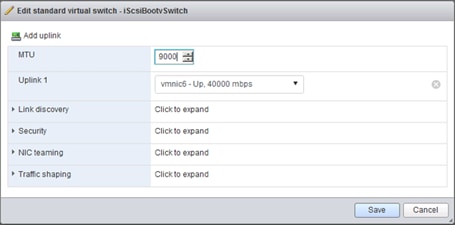
6. Click Save to apply changes.
7. Select the VMkernel NICs tab, right-click vmk1, (which should be the A side iSCSI adapter that was created at install time), and select Edit settings.
8. Change the MTU to 9000 and adjust the IPv4 Address to be an IP outside of the UCS iSCSI-A IP Pool.

9. Click Save.
10. Select the Virtual switches tab, and click on the Add standard virtual switch option.
11. Set the vSwitch Name to iScsiBootvSwitch-B, increase the MTU to 9000, and select vmnic7 for Uplink 1.

12. Click the Add button to create the vSwitch.
13. Click the VMkernel NICs tab within Networking, and select the Add VMkernel NIC option.
14. Provide the following settings for the new VMkernel NIC:
a. Leave the Port group as New port group
b. Enter iScsiBootPG-B for the New port group name
c. Select iScsiBootvSwitch-B as the Virtual switch
d. Leave VLAN ID as 0
e. Adjust MTU to 9000
f. Leave IP version at IP version as IPv4 only
g. Select static for the IPv4 settings
h. Enter an appropriate address on the iSCSI B network that is not in the UCS iSCSI-B IP Pool.
i. Leave TCP/IP stack and Services unchanged.

15. Click Create to add the VMkernel NIC.
16. Repeat these steps on each additional ESXi hosts created.
Setup iSCSI Multipathing
To setup the iSCSI multipathing on the ESXi hosts complete the following steps:
1. From the vSphere Web Client connected to the host, select Storage from within the Navigator options.
2. Click the Adapters tab within Storage, select the iSCSI Software Adapter, and click the Configure iSCSI option.

3. Click Add dynamic target and enter the IP for the first FlashArray iSCSI adapter(ct0.eth8).

4. Repeat the previous step for each additional iSCSI adapter (ct0.eth9, ct1.eth8, ct1.eth9).
5. Click Save configuration.
6. Select the Devices tab within Storage, and click on the Rescan option.
7. Repeat these steps on each additional ESXi host created.
vCenter Installation (optional)
The vCenter Installation steps are optional if using a pre-existing vCenter that sits somewhere else in the data center. These steps will cover the installation of the vCenter Appliance to the first host after the addition of the Infrastructure datastore to the first ESXi host. Begin this optional installation with the following steps:
1. Connect to the first ESXi host with a web browser.
2. Login with the root User name and provide the password set during the ESXi install.
3. Right-click the Storage option within the left side Navigator window, and select New Datastore from the drop-down list.

4. Leave Create new VMFS datastore selected from the New datastore dialogue window for Select creation type, and click Next.
5. The previously provisioned Infrastructure volume should show up as available within the Select device section, enter Infrastructure for the datastore Name and click Next.
6. Leave Use full disk selected within the first pulldown within Select partitioning options, and change the second pull-down from VMFS 5 to VMFS 6.
7. Review the options shown for Ready to complete, and click Finish to provision the datastore.
![]() If not previously downloaded, the vCenter Server Appliance ISO can be downloaded from https://my.vmware.com/group/vmware/details?productId=614&downloadGroup=VC65U1G
If not previously downloaded, the vCenter Server Appliance ISO can be downloaded from https://my.vmware.com/group/vmware/details?productId=614&downloadGroup=VC65U1G
8. Click Networking within the Navigator window, and select the Port groups tab.

9. Right-click the VM Network and select the Edit settings option from the drop-down list.
10. Adjust the VLAN ID from 0 to 115 and click Save.
11. Mount the ISO for the vCenter Server Appliance to the system you have the vSphere Web Client connection to the first ESXi host on.
12. With the ISO mounted, open up the installer.exe from the vcsa-ui-installer\win32 folder within the drive the ISO is mounted to.
13. Click the Install option from the Installer window.

14. Click Next through the Introduction.
15. Select the I accept the terms of the license agreement check box, and click Next.
16. Leave vCenter Server with an Embedded Platform Services Controller selected and click Next.
![]() An External Platform Services Controller can be used to scale to multiple vCenters, but is not covered in this document.
An External Platform Services Controller can be used to scale to multiple vCenters, but is not covered in this document.
17. Specify the IP for the first ESXi host and provide the username and password.

18. Click Next and click Yes to acknowledge the Certificate Warning.
19. Adjust the VM name if desired, and provide an appropriate root password for the appliance in the Set up appliance VM screen. Click Next.
20. Adjust the Deployment size as necessary in the Select deployment size screen and click Next.
21. Select the previously provisioned Infrastructure datastore for the vCenter and click Next.
22. Specify the System name and appropriate IP information for the vCenter.

23. Click Next.
24. Verify the installation summary in the final screen.
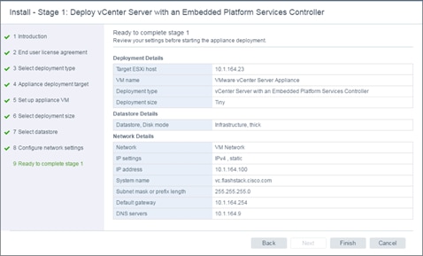
25. Click Finish to start the deployment.

26. After the deployment, click Continue to being the stage 2 of the install.
27. Click Next past the Introduction screen of the Stage 2 dialogue.
28. Specify appropriate IB Mgmt NTP server(s) within the Appliance configuration dialogue, optionally enable SSH to the appliance, and click Next.
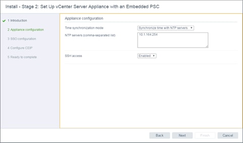
29. Specify a Single Sign-On domain name, confirm a valid password for the Single Sign-On user in the next screen, and set the Site name.
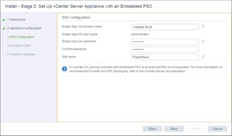
30. Click Next.
31. Choose to opt in, or opt out of VMware’s Customer Experience Improvement Program, and click Next.
32. Verify the Stage 2 installation specifications.

33. Click Finish to install.
Create FlashStack Datacenter
If a new Datacenter is needed for the FlashStack, complete the following steps on the vCenter:
1. Connect to the vSphere Web Client for the vCenter and click Hosts and Clusters from the left side Navigator window, or the Hosts and Clusters icon from the Home center window.

2. Right-click the vCenter icon, and select New Datacenter… from the drop-down list.

3. From the New Datacenter pop-up dialogue enter in a Datacenter name and click OK.

Add the VMware ESXi Hosts Using the VMware vSphere Web Client
To add the VMware ESXi Hosts using the VMware vSphere Web Client, complete the following steps:
1. From the Hosts and Clusters tab, right-click the new or existing Datacenter within the Navigation window, and select New Cluster… from the drop-down list.

2. Enter a name for the new cluster, select the DRS and HA check mark boxes, leaving all other options with defaults.

![]() Admission control may need to be disabled when creating a smaller cluster. Adjust these settings as appropriate to your failover and capacity expectations.
Admission control may need to be disabled when creating a smaller cluster. Adjust these settings as appropriate to your failover and capacity expectations.
3. Click OK to create the cluster.
4. Right-click the newly created cluster and select the Add Host… drop-down list.

5. Enter the IP or FQDN of the first ESXi host and click Next.

6. Enter root for the User Name, provide the password set during initial setup, and click Next.
7. Click Yes in the Security Alert pop-up to confirm the host’s certificate.
8. Click Next past the Host summary dialogue.
9. Provide a license by clicking the green + icon under the License title, select an existing license, or skip past the Assign license dialogue by clicking Next.
10. Leave lockdown mode Disabled within the Lockdown mode dialogue window and click Next.
11. Skip past the Resource pool dialogue by clicking Next.
12. Confirm the Summary dialogue and add the ESXi host to the cluster by clicking Next.

13. Repeat these steps for each ESXi host to be added to the cluster.
14. Secondary hosts will need to rescan for storage to make the Infrastructure datastore accessible to them. This can be performed from the Configure tab of the host view, selecting Storage Adapters within the Storage category.

15. Click OK to scan and recognize the VMFS volume holding the Infrastructure datastore.
Configure Virtual Networking
The virtual network deployment scenario sets up one dedicated infrastructure vDS with management and vMotion traffic, two dedicated vSwitches for the respective A and B iSCSI networks that have already been set up on the local ESXi configuration, and one APIC implemented application vDS that can be dynamically configured with tenant needs.
![]() This specific layout of the virtual networking is not required within FlashStack, but care should be taken when deviating from these steps to not impact functionality.
This specific layout of the virtual networking is not required within FlashStack, but care should be taken when deviating from these steps to not impact functionality.
FlashStack Infrastructure vDS
To configure the first VMware vDS, complete the following steps:
1. Connect to the vSphere Web Client and click Networking from the left side Navigator window, or the Networking icon from the Home center window.
2. Right-click the FlashStack-ACI datacenter and select Distributed Switch > New Distributed Switch.

3. Give the Distributed Switch a descriptive name, Infra-DSwitch in our example, and click Next.
4. Make sure Distributed switch: 6.5.0 is selected and click Next.
5. Leave the Number of uplinks at 4. If VMware Network I/O Control is to be used for Quality of Service, leave Network I/O Control Enabled. Otherwise, Disable Network I/O Control. Enter IB-Mgmt for the name of the default Port group to be created. Click Next.
6. Review the information and click Finish to complete creating the vDS.

7. Right-click the newly created vDS on the left, and select Settings -> Edit Settings…
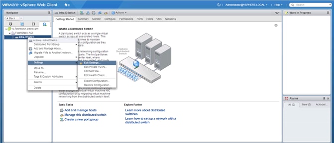
8. Click the Advanced option on the left side of the Edit Settings window, and adjust the MTU from 1500 to 9000.

9. Click OK to save the changes.
10. On the left, expand the FlashStack ACI datacenter and the newly created vDS.
11. Right-click the IB-Mgmt Distributed Port Group, and select Edit Settings…
12. Click VLAN, changing VLAN type from None to VLAN, and enter in the appropriate VLAN number for the IB-Mgmt network.
13. Click on the Teaming and Failover and move the Uplinks 3 & 4 to the Unused uplinks state, and move the Uplink 2 to the Standby uplinks state.
![]() Movement of Uplink 2 to standby is guiding Management traffic to stay within the A side fabric contained within Uplink 1 to prevent unnecessary traffic hops up into the Nexus switch to traverse between fabrics. Uplinks 3 & 4 are set as unused as these are the vMotion vNICs and will be used by the other Distributed Port Group in this vDS.
Movement of Uplink 2 to standby is guiding Management traffic to stay within the A side fabric contained within Uplink 1 to prevent unnecessary traffic hops up into the Nexus switch to traverse between fabrics. Uplinks 3 & 4 are set as unused as these are the vMotion vNICs and will be used by the other Distributed Port Group in this vDS.

14. Click OK to save the changes.
15. Right-click the infrastructure vDS (Infra-DSwitch), and select Distributed Port Group -> New Distributed Port Group…
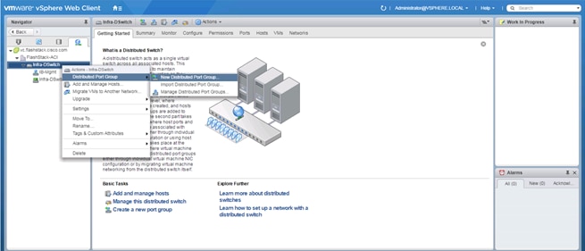
16. Name the new Port Group vMotion and click Next.
17. Change the VLAN type from None to VLAN, select the VLAN ID appropriate for your vMotion traffic, and select the Customize default policies configuration check box under the Advanced section.

18. Click Next.
19. Click Next through the Security and Traffic Shaping sections.
20. Within the Teaming and failover section, move Uplinks 1 & 2 to the Unused uplinks section, and move Uplink 3 to the Standby uplinks section.
![]() Teaming for the vMotion Distributed Port Group will be a mirror of teaming on the Infrastructure Distributed Port group. Uplinks 1 & 2 are unused because they are used by the Infrastructure Distributed Port group, and Uplink 3 will be moved to standby to guide vMotion traffic to stay within the B side fabric contained within Uplink 4.
Teaming for the vMotion Distributed Port Group will be a mirror of teaming on the Infrastructure Distributed Port group. Uplinks 1 & 2 are unused because they are used by the Infrastructure Distributed Port group, and Uplink 3 will be moved to standby to guide vMotion traffic to stay within the B side fabric contained within Uplink 4.

21. Click Next.
22. Click Next past Monitoring, Miscellaneous, and Edit additional settings sections.
23. Review the Ready to complete section.

24. Click Finish to create the Distributed Port Group.
FlashStack Application vDS
The second VMware vDS for application use will be configured through the Cisco APIC allowing for the required configuration to occur within the ACI fabric and the vCenter vDS with a single set of steps.
To create the Application vDS from the APIC Advanced GUI, complete the following steps:
1. Log into the APIC Advanced GUI using the admin user.
2. At the top, click Virtual Networking.
3. In the center pane within Quick Start, select the Create a vCenter Domain Profile option under Steps.
4. In the Create vCenter Domain window that appears, enter the vDS name as it should appear in vCenter.
5. Leave VMware vSphere Distributed Switch selected for the vSwitch.
6. Select the UCS Attachable Entity Profile.
7. For VLAN Pool, select Create VLAN Pool from the pull-down options.
8. Provide a Name for the pool to be associated to the vDS.
9. Leave the Allocation Mode set to Dynamic Allocation.
10. Click on the + icon at the right side of the Encap Blocks section.
11. Set an appropriate VLAN range.
12. Set the Allocation Mode to Dynamic Allocation.
13. Leave the Role as External or On the wire encapsulations.

14. Click OK.

15. Click Submit.
16. Click the + icon at the right side of the vCenter Credentials section.
17. Specify a Name for the credentials, along with the appropriate account Username and Password.

![]() The vCenter Administrator account is used in this example, but a dedicated APIC account can be created within the vCenter using the minimum set of needed privileges as specified here: https://www.cisco.com/c/en/us/td/docs/switches/datacenter/aci/apic/sw/3-x/virtualization/b_ACI_Virtualization_Guide_3_1_1/b_ACI_Virtualization_Guide_3_1_1_chapter_011.html#concept_4954018D4D4943BBBB565949752BA1F9.
The vCenter Administrator account is used in this example, but a dedicated APIC account can be created within the vCenter using the minimum set of needed privileges as specified here: https://www.cisco.com/c/en/us/td/docs/switches/datacenter/aci/apic/sw/3-x/virtualization/b_ACI_Virtualization_Guide_3_1_1/b_ACI_Virtualization_Guide_3_1_1_chapter_011.html#concept_4954018D4D4943BBBB565949752BA1F9.
18. Click OK.

19. Click the + icon at the right side of the vCenter section.
20. In the Add vCenter Controller window, enter a name for the vCenter. The name used in this deployment is FSV-vCenter.
21. Enter the vCenter IP Address or Host Name.
22. For DVS Version, leave as vCenter Default.
23. Set Stats Collection to Enabled.
24. For Datacenter, enter the exact vCenter Datacenter name (FlashStack-ACI).
25. Do not select a Management EPG.
26. For vCenter Credential Name, select the vCenter credentials created in the last step (Administrator).

27. Click OK to add the vCenter Controller.
28. In the Create vCenter Domain Window, select the MAC Pinning-Physical-NIC-load as the Port Channel Mode.
29. Select CDP vSwitch Policy.
30. Leave the Netflow Exporter Policy unselected.

31. Click Submit to create the vDS within the FlashStack vCenter.
32. Log into the vCenter vSphere Web Client and navigate to Networking.
33. A distributed switch should have been added.

34. In the APIC GUI, select Tenants > common.
35. Under Tenant common, expand Application Profiles > FSV-Common-IB-Mgmt > Application EPGs > Common-Core-Services.
36. Under the Common-Core-Services EPG, right-click Domains and select Add VMM Domain Association.
37. Use the pulldown to select the FSV-Application VMM Domain Profile. Select Immediate Deploy Immediacy and change no other values. Click Submit to create the Common-Core-Services port group in the vDS.

Add ESXi hosts to the Infrastructure vDS
To add the VMware ESXi Hosts to the Infrastructure vDS, complete the following steps:
1. Log into the vSphere Web Client.
2. From the Home screen, select Networking under Inventories.
3. In the left, expand the Datacenter and the VDS folder. Select the Infra-DSwitch that was created for management and vMotion traffic.
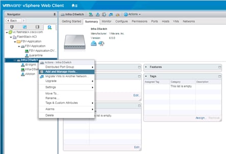
4. Right-click the VDS switch and select Add and manage hosts.
5. In the Add and Manage Hosts window, make sure the option Add hosts is selected and click Next.
6. Click + to add New hosts.
7. In the Select new hosts window, select all of the relevant ESXi hosts.

8. Click OK to complete the host selection.
9. Click Next.
10. Leave Manage physical adapters and Manage VMkernel adapters both selected. If the vCenter has been deployed within the FlashStack, also select Migrate virtual machine networking.

11. Click Next.
12. Select vmnic1 from the Host/Physical Network Adapters column.

13. Click the Assign uplink option.

14. Select Uplink 2 and click OK.
![]() vmnic0 assignment to Uplink 1 is left out at this point to maintain connectivity to the vCenter. If the vCenter has not been deployed to the FlashStack, vmnic0 assignment to Uplink 1 can occur at this time.
vmnic0 assignment to Uplink 1 is left out at this point to maintain connectivity to the vCenter. If the vCenter has not been deployed to the FlashStack, vmnic0 assignment to Uplink 1 can occur at this time.

15. Repeat this step for vmnic2-3, assigning them to uplinks 3-4 in corresponding sequence.

16. Repeat these assignment for all additional ESXi hosts being configured.

17. Click Next.

18. Select the vmk0 of the first host and click on the Assign port group option.

19. Select the IB-Mgmt destination port group and click OK.
20. Repeat this step for all additional hosts being configured.

21. Click Next.
22. Click Next past Analyze impact.
23. If the vCenter has been deployed, expand the Virtual Machine within the Host listing, select the Network adapter and click Assign port group.

24. Select the IB-Mgmt Network from the provided options and click OK.

25. Click Next.

26. Review the settings and click Finish to apply.
27. Select the first host, and select Virtual switches within the Configure tab.

28. Select vSwitch0 and click the red X icon under Virtual switches to remove the Switch.
29. Select the Infra-DSwitch vDS within Virtual switches.

30. Click the third icon under Virtual switches to Manage the physical network adapters connected to the virtual switch.
31. Select Uplink 1 and click the green + icon to Assign Physical Adapter to the Switch.

32. With vmnic0 selected, click OK to assign the Network adapter.
33. Click OK to apply the assignment.
34. Perform these steps for each additional ESXi host deployed.
Add ESXi Hosts to the Application vDS
To add the VMware ESXi Hosts to the Application vDS, complete the following steps:
1. Log into the vSphere Web Client.
2. From the Home screen, select Networking under Inventories.
3. In the left, expand the Datacenter and the vDS folder. Select the FSV-Application vDS that was created by the APIC.

4. Right-click the VDS switch and select Add and manage hosts.
5. In the Add and Manage Hosts window, make sure the option Add hosts is selected; click Next.
6. Click + to add New hosts.
7. In the Select new hosts window, select all of the relevant ESXi hosts.
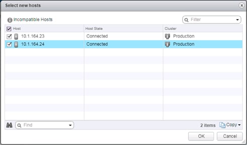
8. Click OK to complete the host selection.
9. Click Next.
10. Leave Manage physical adapters selected and de-select both of the other options.

11. Click Next.
12. Select vmnic4 from the Host/Physical Network Adapters column.

13. Click the Assign uplink option.

14. Leave Uplink 1 selected and click OK.
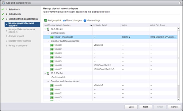
15. Repeat this process for vmnic5, assigning it to uplink2.
![]() The uplinks created for this vDS by the APIC will be 8 even though we are only using 2. Adjustments to the uplink count directly from vCenter should not be made as this can lead to misconfigurations of what the APIC is expecting for this vDS.
The uplinks created for this vDS by the APIC will be 8 even though we are only using 2. Adjustments to the uplink count directly from vCenter should not be made as this can lead to misconfigurations of what the APIC is expecting for this vDS.

16. Repeat these assignment for all additional ESXi hosts being configured.

17. Click Next.
18. Click Next past Analyze impact.
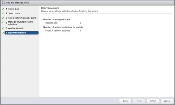
19. Review the settings and click Finish to apply.
Add a vMotion vmkernel
1. Select the VMkernel adapters within the Configure tab for the first host.

2. Click the first icon under VMkernel adapters to Add host networking.
3. Leave VMkernel Network Adapter selected and click Next.
4. Leave Select an existing network selected and click Browse.

5. Select the vMotion network from the Distributed Switch and click OK.
6. Click Next.
7. Select the vMotion option under Available services.

8. Click Next.
9. Select the Use static IPv4 settings option and provide an appropriate IPv4 and Subnet mask settings for vMotion traffic to use between the ESXi hosts.
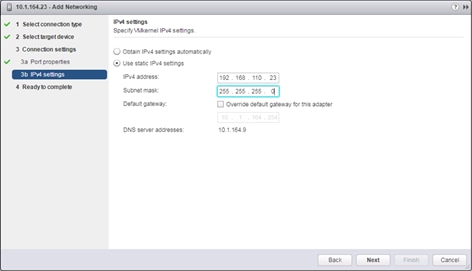
10. Click Next.
11. Review the Ready to complete summary and click Finish to add the vMotion VMkernel adapter.
12. Select the provisioned VMkernel adapter within the Configure tab for the host.

13. Click the third icon over to edit the settings for the vMotion VMkernel
14. Select the NIC settings option and change the MTU from 1500 to 9000.

15. Click OK to apply the changes
16. Repeat these steps for each additional ESXi host deployed.
Pure Storage vSphere Web Client Plugin
The Pure Storage vSphere Web Client Plugin will be accessible through the vSphere Web Client after registration through the Pure Storage Web Portal.
![]() The Purity 4.10.5 release comes with the 2.5.1 version of the plugin, which will work, but will provision VMFS-5 datastores, instead of the recommended VMFS-6 datastores. The example below shows an early release of the 3.0 plugin, which can be installed to the FlashArray by submitting a support request with Pure Support asking for the plugin upgrade. This is not a requirement, but to use VMFS-6 datastores in the absence of the upgraded plugin, LUNs would need to be manually provisioned through the Purity Web Console, and VMFS-6 datastore would be created from the LUNs within vCenter.
The Purity 4.10.5 release comes with the 2.5.1 version of the plugin, which will work, but will provision VMFS-5 datastores, instead of the recommended VMFS-6 datastores. The example below shows an early release of the 3.0 plugin, which can be installed to the FlashArray by submitting a support request with Pure Support asking for the plugin upgrade. This is not a requirement, but to use VMFS-6 datastores in the absence of the upgraded plugin, LUNs would need to be manually provisioned through the Purity Web Console, and VMFS-6 datastore would be created from the LUNs within vCenter.
To access the Pure Storage vSphere Web Client Plugin, complete the following steps:
1. Go to System -> Plugins -> vSphere.

2. Enter the vCenter Host IP or FQDN, the Administrator User to connect with, the password for the Administrator User, and click Connect. Once connected, select the Install button to register the plugin.
3. With the plugin registered, connect to the vSphere Web Client and select the Pure Storage Plugin from the Home page.

4. Click Add FlashArray within the options under the Object tab.

5. Enter the FlashArray Name, FlashArray URL, Username and Password in the Add FlashArray pop-up window.

6. Click Add to register the FlashArray//X within the plugin.
Add Datastores
These steps add a datastore to place VMs on the FlashArray//X and optionally a second datastore for keeping their swapfiles.
![]() A dedicated swapfile location will not provide a performance increase over the existing all flash datastores created from the FlashArray//X, but can be useful to have these files in a separate location to have them excluded from snapshots and backups.
A dedicated swapfile location will not provide a performance increase over the existing all flash datastores created from the FlashArray//X, but can be useful to have these files in a separate location to have them excluded from snapshots and backups.
1. Right-click the cluster and select the Pure Storage -> Create Datastore option from the drop-down list.

2. Give the Datastore Name a value appropriate for VM store in the environment, select a starting size for the Datastore Size, click the VMFS 6 selection under VMFS Options, and click Create to provision the volume.

3. Optionally, repeat these similar steps to create a swap datastore to be used by the ESXi hosts. Right-click the cluster and select the Pure Storage -> Create Datastore option from the drop-down lis.
4. Give the Datastore Name a value appropriate for VM swapfiles on the ESXi host, select a starting size for the Datastore Size, click the VMFS 6 selection under VMFS Options, and click Create to provision the volume.
Configure ESXi Hosts in the Cluster
With the hosts added and the base vCenter configuration complete, some additional configurations will be needed for each ESXi host provisioned for the FlashStack.
Configure ESXi Settings
A couple of base settings are needed for stability of the vSphere environment, as well as optional enablement of SSH connectivity to each host for the updating of drivers.
To configure ESXi settings, complete the following steps:
1. Select the first ESXi host to configure with standard settings.
2. Select the Configure tab and select Time Configuration within the options on the left under System, and click Edit within Time Configuration.

3. Select Use Network Time Protocol (Enable NTP client), enter the NTP Server(s), select Start and stop with port usage for NTP Service Startup Policy, and click Start within NTP Service Status.
4. Click OK to submit the changes.
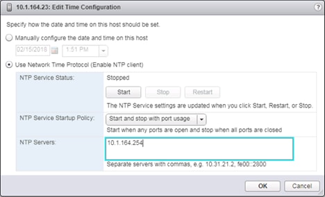
5. (Optional) Click Security Profile within the Configure tab under the System section for the host.
![]() Security Profile settings of ESXi Shell and SSH are enabled for the update of the nenic driver later. These steps are unnecessary if using VMware Update Manager and these drivers are being handled by being included into a configured baseline. If SSH is enabled for updates, it is recommended to later disable this service if it is considered a security risk in the environment.
Security Profile settings of ESXi Shell and SSH are enabled for the update of the nenic driver later. These steps are unnecessary if using VMware Update Manager and these drivers are being handled by being included into a configured baseline. If SSH is enabled for updates, it is recommended to later disable this service if it is considered a security risk in the environment.

6. Scroll down to the Services section within Security Profile and click Edit.

7. Select the ESXi Shell entry, change the Startup Policy to Start and stop with port usage, and click Start. Repeat these steps for the SSH entry. Click OK.
8. If an optional ESXi swap datastore was configured earlier, click the cluster the hosts have been added to, select the Configure tab, and select General within Configuration.

9. Click the Edit button to the right of Swap file location.
10. Change the selected option to Datastore specified by host.

11. Click OK.
12. Within the first ESXi host, select Swap file location from the Virtual Machines section of the Configure tab.
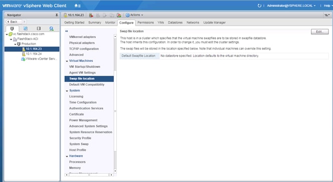
13. Click Edit.
14. Select the provisioned datastore for VM swap use.
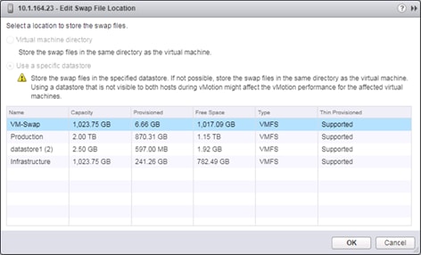
15. Click OK to add it as a Swap File location.
16. Repeat these steps on each ESXi host being added into the cluster.
Install VMware Driver for the Cisco Virtual Interface Card (VIC)
The Cisco Custom Image for VMware vSphere 6.5 U1 comes with the currently specified nenic 1.0.6.0 for Ethernet traffic from the ESXi host, which has a recommendation for upgrade to the 1.0.13.0 version of the nenic. For the most recent versions, please refer to Cisco UCS HW and SW Availability Interoperability Matrix. VMware Update Manager can be used for these updates, but is not covered in this document.
To install VMware VIC Drivers on the ESXi hosts using esxcli, complete the following steps:
1. Download and extract the driver bundle to the system the vSphere Web Client is running from.
2. Within the vSphere Web Client, select one of the datastores common to all of the hosts.

3. Click the Upload a file to the Datastore button.
4. Select and upload the offline_bundle (VMW-ESX-6.5.0-nenic-1.0.13.0-offline_bundle-7098243.zip) from the extracted driver download.
5. Place all hosts in Maintenance mode requiring update.
6. Connect to each ESXi host through ssh from a shell connection or putty terminal.
7. Login as root with the root password.
8. Run the following command (substituting the appropriate datastore directory if needed) on each host:
esxcli software vib update -d /vmfs/volumes/Infrastructure/VMW-ESX-6.5.0-nenic-1.0.13.0-offline_bundle-7098243.zip
9. Reboot each host by typing reboot from the SSH connection after the command has been run.
10. Log into the Host Client on each host once reboot is complete.
ESXi Spectre Patch
The ESXi installation ISOs available at the time of the writing of this CVD do not incorporate recently released fixes for the Speculative Execution (Spectre) vulnerability. The patches released to address these fixes are available within release ESXi650-201803001 via download from VMware. Details of these patches are addressed in VMware bulletins ESXi650-201803401-BG and ESXi650-201803402-BG.
These patches should be installed using the VMware Update Manager, or can be installed using the manual installation method mentioned in the previous section with:
esxcli software vib update -d /vmfs/volumes/Infrastructure/ESXi650-201803001.zip
Further details of the implementation of these patches can be found at: https://kb.vmware.com/s/article/52085
ESXi Dump Collector Setup for iSCSI-Booted Hosts
ESXi hosts booted with iSCSI using the VMware iSCSI software initiator need to be configured to do core dumps to the ESXi Dump Collector that is part of vCenter. The Dump Collector is not enabled by default on the vCenter Appliance.
To setup the ESXi Dump Collector, complete the following steps:
1. In the vSphere web client, select Home.
2. In the center pane, click System Configuration under the Administration section.
3. In the left pane, select Services.
4. Under services, click VMware vSphere ESXi Dump Collector.
5. In the center pane, click the green start icon to start the service.
6. In the Actions menu, click Edit Startup Type.
7. Select Automatic.
8. Click OK.
9. Connect to each ESXi host via ssh as root
10. Run the following commands:
esxcli system coredump network set –v vmk0 –j <vcenter-ip>
esxcli system coredump network set –e true
esxcli system coredump network check
Cisco UCS Manager Plug-in for VMware vSphere Web Client
The Cisco UCS Manager Plug-in for VMware vSphere Web Client allows administration of UCS domains through the VMware’s vCenter administrative interface. The capabilities of the plug-in include:
· View Cisco UCS physical hierarchy
· View inventory, installed firmware, faults, power and temperature statistics
· Map the ESXi host to the physical server
· Manage firmware for Cisco UCS B and C series servers
· Launch the Cisco UCS Manager GUI
· Launch the KVM consoles of UCS servers
· Switch the existing state of the locator LEDs
The installation is only valid for VMware vCenter 5.5 or higher, and will require revisions of .NET Framework 4.5 and VMware PowerCLI 5.1 or greater on the system used to install Cisco UCS Manager Plugin from.
Cisco UCS Manager Plug-in Installation
1. Download the plugin and registration tool from: https://software.cisco.com/download/release.html?mdfid=286282669&catid=282558030&softwareid=286282010&release=2.0.3
2. Place the downloaded ucs-vcplugin-2.0.3.zip file on an accessible web server previously used for hosting the VMware ESXi ISO.
3. Extract the Cisco_UCS_Plugin_Registration_Tool_1_1_3.zip and open the executable file within it.
4. Leave Register Plugin selected for the Action and fill in:
a. IP/Hostname
b. Username
c. Password
d. URL that plugin has been uploaded to
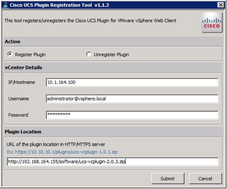
5. A pop-up will appear explaining that ‘allowHttp=true’ will need to be added to the webclient.properties file on the VCSA in the /etc/vmware/vsphere-client directory.
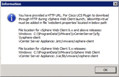
6. Take care of this issue after the plugin has been registered, click OK to close the Information dialogue box.
7. Click Submit to register the plugin with the vCenter Server Appliance.
8. To resolve the change needed for the HTTP download of the vSphere Web Client launch, connect to the VCSA with ssh using the root account and edit /etc/vmware/vsphere-client/webclient.properties to add “allowHttp=true” or type:
echo ’allowHttp=true’ >> /etc/vmware/vsphere-client/webclient.properties
![]() This will add “allowHttp=true” to the end of the webclient.properties file. Make sure to use two greater than symbols “>>” to append to the end of the configuration file, a single greater than symbol will replace the entire pre-existing file with what has been sent with the echo command.
This will add “allowHttp=true” to the end of the webclient.properties file. Make sure to use two greater than symbols “>>” to append to the end of the configuration file, a single greater than symbol will replace the entire pre-existing file with what has been sent with the echo command.
9. Reboot the VCSA.
FlashStack UCS Domain Registration
Registration of the FlashStack UCS Domain can now be performed. The account used will correlate to the permissions allowed to the plugin, admin will be used in our example, but a read only account could be used with the plugin if that was appropriate for the environment.
To register the UCS Domain, complete the following steps:
1. Opening up the vSphere Web Client.
2. Select the Home from the Navigator or drop-down list, and double click the Cisco UCS icon appearing in the Administration section.

3. Click the Register button and provide the following options in the Register UCS Domain dialogue box that appears:
a. UCS Hostname/IP
b. Username
c. Password
d. Port (if different than 443)
e. Leave SSL selected and click the Visible to All users option
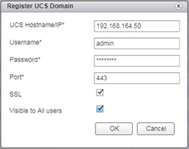
4. Click OK to register the UCS Domain.
Using the Cisco UCS vCenter Plugin
1. The plugin can now enable the functions described at the start of this section by double-clicking the registered UCS Domain:

This will display the components associated to the domain:

2. Selecting within the chassis or rack mounts will provide a list of ESXi or non-ESXi servers to perform operations on the following:

3. In addition to viewing and working within objects shown in the UCS Plugin’s view of the UCS Domain, direct access of UCS functions provided by the plugin can be selected within the drop-down list of hosts registered to vCenter or within the Summary page of the ESXi host:
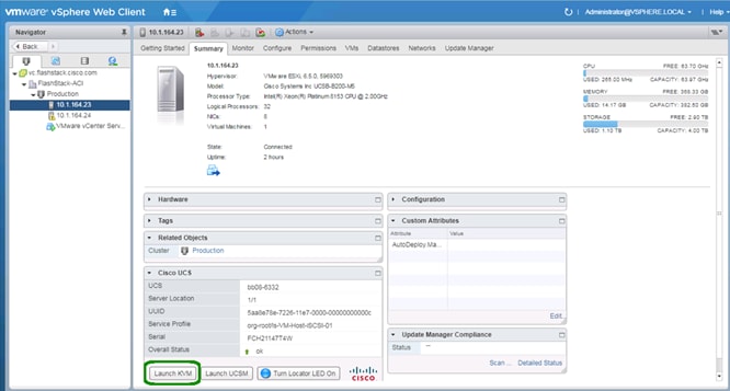
For full installation instructions and usage information, please refer to the Cisco UCS Manager Plug-in for VMware vSphere Web Client User Guide.
Cisco ACI vCenter Plugin
The ACI vCenter Plugin will allow completion of basic ACI fabric configurations within the vSphere Web Client connection to the vCenter. Installing this plugin will require availability of the plugin package from a web server that is accessible to the vCenter server, and invocation of the installation script from a system with the VMware vSphere PowerCLI installed.
1. Using web browser, go to the APIC at https://<apic-ip>/vcplugin.
2. Download the vcenter-plugin-3.1.1000.9.zip Plugin Archive, and the ACIPlugin-Install.ps1.
3. Transfer the vcenter-plugin-3.1.1000.9.zip file contained in the extracted vcenter-plugin-3.1.1000.9 folder to the web server used for the UCS vMedia and or the UCS Manager Plugin installation.
4. Copy the extracted ACIPlugin-Install.ps1to the system with PowerCLI in place if it was not the download host.
5. In a PowerCLI session, run the ACIPlugin-Install.ps1 script.

6. Enter the address to the vCenter and the http source for the plugin bundle, provide the appropriate vCenter credentials to the pop-up.
7. After disconnecting from any current vCenter connections through the vSphere Web Client, the plugin should show up within the Home screen:

Pure Storage Best Practices for vSphere
The Pure Storage FlashArray has a few necessary changes for VMware ESXi. The following are some requirements and considerations:
· Virtual Disk Types: Pure Storage recommends thin type virtual disks for the majority of virtual machines. Thin virtual disks are the most flexible and provide benefits such as in-guest space reclamation support. For virtual machines that demand the lowest possible latency with the most consistent performance, eagerzeroedthick virtual disks should be used. The use of zeroedthick (aka “lazy” or “sparse”) is discouraged at all times.
· Virtual Machine SCSI adapter: Pure Storage recommends using the Paravirtual SCSI adapter in virtual machines to provide access to virtual disks/RDMs. The Paravirtual SCSI adapter provides the highest possible performance levels with the most efficient use of CPU during intense workloads. Virtual machines with small I/O requirements can use the default adapters if preferred.
· Volume sizing and volume count: Pure Storage has no recommendations around volume sizing or volume count. The FlashArray volumes have no artificially limited queue depth, not on the volume level or the port level. A single volume can use the entire performance of the FlashArray if needed. In the case of very large volumes, or volumes serving intense workloads it might be necessary to increase internal queues inside of ESXi (HBA device queue, Disk.SchedNumReqOutstanding, virtual SCSI adapter queue).
· VMFS-6 is the recommended datastore type to enable automatic Run Space Reclamation (UNMAP) to ensure the FlashArray capacity usage accurately reflects the actual usage inside of VMware.
· With iSCSI configured for the FlashArray, disable DelayedAck and increase the Login Timeout to 30 seconds (from a value of 5).

This section details the steps for creating a sample two-tier application called FSV-App-A. This tenant will comprise of a Web and an App tier which will be mapped to relevant EPGs on the ACI fabric.
To deploy the Application Tenant and associate it to the VM networking, complete the steps in the following sections.
Configure Tenant
1. In the APIC Advanced GUI, select Tenants.
2. At the top select Tenants > Add Tenant.
3. Name the Tenant FSV-App-A.
4. For the VRF Name, also enter FSV-App-A. Leave the Take me to this tenant when I click finish checkbox checked.
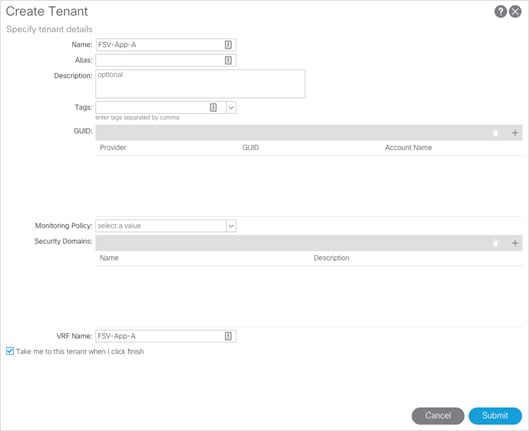
5. Click Submit to finish creating the Tenant.
Configure Bridge Domains
At least one bridge domain will need to be created. In the following steps, an internal versus an external bridge domain is created to allow an optional insertion of a firewall between EPGs connecting from the differing bridge domains. Insertion and configuration of this firewall is not covered in this document.
1. In the left pane expand Tenant FSV-App-A > Networking.
2. Right-click the Bridge Domain and select Create Bridge Domain.
3. Name the Bridge Domain App-A-External, select FSV-App-A for the VRF, select Forwarding as Custom, and change L2 Unknown Unicast to Flood.

4. Click Next.
5. Within the L3 Configurations section, select the checkbox for GARP based detection of the EP Move Detection Mode.

6. Next and click Finish to complete adding the Bridge Domain.
7. Repeat the steps above to add another Bridge Domain named App-A-Internal.
Configure Application Profile
1. In the left pane, right-click Application Profiles and select Create Application Profile.
2. Name the Application Profile App-A and click Submit.

Configure End Point Groups
EPG for Web
1. In the left pane expand Application Profiles > App-A.
2. Right-click Application EPGs and select Create Application EPG.
3. Name the EPG Web. Leave Intra EPG Isolation Unenforced.
4. From the Bridge Domain drop-down list, select App-A-External.
5. Check the check box next to Associate to VM Domain Profiles.

6. Click Next.
7. Click + to Associate VM Domain Profiles.
8. From the Domain Profile drop-down list, select VMware/FSV Application domain profile.

9. Change the Deployment Immediacy to Immediate.
10. Change the Resolution Immediacy to Pre-provision.
11. Click Update.
12. Click Finish to complete creating the EPG.
13. In the left pane expand EPG Web, right-click on the Subnets and select Create EPG Subnet.
14. For the Default Gateway IP, enter a gateway IP address and mask. In this deployment, the GW address configured for Web VMs is 172.18.101.254/24.
15. Since the Web VM Subnet is advertised to Nexus 7000s and to App EPG, select Advertise Externally and Shared between the VRFs.

16. Click Submit.
![]() At this point, a new port-group should have been created on the VMware VDS. Log into the vSphere Web Client, browse to Networking > VDS and verify.
At this point, a new port-group should have been created on the VMware VDS. Log into the vSphere Web Client, browse to Networking > VDS and verify.

EPG for App
1. In the left pane expand Application Profiles > App-A.
2. Right-click Application EPGs and select Create Application EPG.
3. Name the EPG App. Leave Intra EPG Isolation Unenforced.
4. From the Bridge Domain drop-down list select FSV-App-A/App-A-Internal.
5. Check the check box next to Associate to VM Domain Profiles.

6. Click Next.
7. Click + to Associate VM Domain Profiles.
8. From the Domain Profile drop-down list, select VMware/FSV-Application domain profile.
9. Change the Deployment Immediacy to Immediate.
10. Change the Resolution Immediacy to Pre-provision.

11. Click Update.
12. Click Finish to complete creating the EPG.
13. In the left pane expand EPG App-A-App, right-click on the Subnets and select Create EPG Subnet.
14. For the Default Gateway IP, enter a gateway IP address and mask. In this deployment, the GW address configured for App VMs is 172.18.102.254/24.
15. Since the App VMs only need to communicate with Web VMs EPG, select Private to VRFs.

16. Click Submit.
![]() At this point, a new port-group should have been created on the VMware VDS. Log into the vSphere Web Client, browse to Networking > VDS and verify.
At this point, a new port-group should have been created on the VMware VDS. Log into the vSphere Web Client, browse to Networking > VDS and verify.

Configure Contracts
App-Tier to Web-Tier Contract
Provided Contract in EPG App-A-App
1. In the APIC Advanced GUI, select Tenants > FSV-App-A.
2. In the left pane, expand Tenant FSV-App-A > Application Profiles > App-A > Application EPGs > App.
3. Right-click on Contract and select Add Provided Contract.
4. In the Add Provided Contract window, from the Contract drop-down list, select Create Contract.

5. Name the Contract Allow-Web-to-App.
6. Select Tenant for Scope.
7. Click + to add a Contract Subject.
8. Name the subject Allow-Web-to-App.
9. Click + to add a Contract filter.

10. Click + to add a new Subject.

11. For Filter Identity Name, enter Allow-Web-A-All.
12. Click + to add an entity.

13. Enter Allow-All as the name of Entries.
14. From the EtherType drop-down list, select IP.

15. Click Update.
16. Click Submit.
17. Click Update in the Create Contract Subject window.
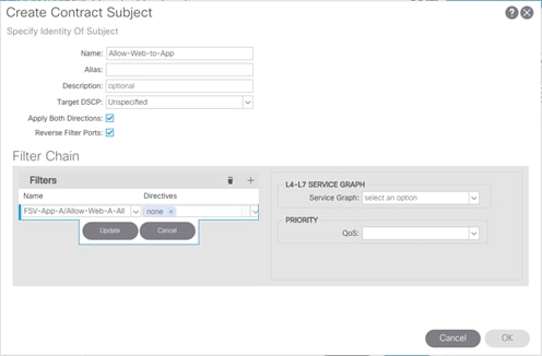
18. Click OK to finish creating the Contract Subject.

19. Click Submit to complete creating the Contract.
20. Click Submit to complete adding the Provided Contract.
Consume Contract in EPG App-A-Web
1. In the left pane expand Tenant FSV-App-A > Application Profiles > App-A > Application EPGs > Web.
2. Right-click Contracts and select Add Consumed Contract.
3. In the Add Consumed Contract window, use the drop-down list to select the contract defined in the last step, App-A/Allow-App-to-Web.

4. Click Submit to complete adding the Consumed Contract.
![]() The communication between Web and App tiers of the application should be enabled now. Customers can use more restrictive contracts to replace the Allow-All contract defined in this example.
The communication between Web and App tiers of the application should be enabled now. Customers can use more restrictive contracts to replace the Allow-All contract defined in this example.
6. Repeat these equivalent steps to add FSV-Allow-Common-Core-Services as a consumed contract to the App EPG.
Web-Tier to Shared L3 Out Contract
To enable App-A’s Web VMs to communicate outside the Fabric, Shared L3 Out contract defined in the Common Tenant will be consumed in the Web EPG. To enable traffic from Web VMs to outside the fabric, complete the following steps :
1. In the APIC Advanced GUI, select Tenants > FSV-App-A.
2. In the left pane, expand Tenant FSV-App-A > Application Profiles > App-A > Application EPGs > Web.
3. Right-click Contracts and select Add Consumed Contract.
4. In the Add Consumed Contract window, use the drop-down list to select common/Allow-Shared-L3Out-All.

5. Click Submit to complete adding the Consumed Contract.
6. Log into the core Nexus 7000 switch to verify App-A-Web EPG’s subnet (172.18.101.0/24) is being advertised.

With the provisioning of the Web and App EPGs and the application of the created contracts, the environment is now set for both tiers to have access to the Core Services network to reach AD and similar services, while the App tier is protected to limit access down to the Web tier initiated IP conversations.
A high-level summary of the FlashStack validation is provided in this section. The solution was validated for basic data forwarding by deploying virtual machine running IOMeter tool as well as basic tests of connectivity and isolation within L2 and L3 as implemented within ACI. The system was validated for resiliency by failing various aspects of the system under load. Examples of the types of tests executed include:
· Access between tenant EPGs
· Failure and recovery of iSCSI booted ESXi hosts in a cluster
· Service Profile migration between blades
· Failure of partial and complete IOM links
· Failure and recovery of redundant links to FlashArray controllers
· Storage link failure between one of the FlashArray controllers and the fabric interconnect
· Load was generated using IOMeter tool and different IO profiles were used to reflect the different profiles that are seen in customer networks
This FlashStack release delivers an application centric architecture for enterprise and cloud datacenters using Cisco UCS Blade Servers, Cisco Fabric Interconnects, Cisco Nexus 9000 switches, utilizing iSCSI attached Pure Storage FlashArray//X. FlashStack is designed and validated using compute, network and storage best practices for high performance, high availability, and simplicity in implementation and management.
This CVD validates the design, performance, management, scalability, and resilience that FlashStack provides to customers. This validation included a full deployment and documentation of the latest supported releases of all products involved. Testing of component failures within each layer of the design, as well as network traffic verification to differing segments connected within the Cisco ACI fabric configuration.
Products and Solutions
Pure Storage FlashArray//X:
https://www.purestorage.com/products/flasharray-x.html
Cisco Unified Computing System:
http://www.cisco.com/c/en/us/products/servers-unified-computing/index.html
Cisco UCS 6300 Series Fabric Interconnects:
Cisco UCS 5100 Series Blade Server Chassis:
Cisco UCS B-Series Blade Servers:
Cisco UCS Adapters:
Cisco UCS Manager:
http://www.cisco.com/c/en/us/products/servers-unified-computing/ucs-manager/index.html
Cisco Nexus 9000 Series Switches:
http://www.cisco.com/c/en/us/products/switches/nexus-9000-series-switches/index.html
Cisco Application Centric Infrastructure:
https://www.cisco.com/c/en_au/solutions/data-center-virtualization/aci.html
VMware vCenter Server:
http://www.vmware.com/products/vcenter-server/overview.html
VMware vSphere:
https://www.vmware.com/products/vsphere
Ramesh Isaac, Technical Marketing Engineer, Cisco Systems, Inc.
Ramesh Isaac is a Technical Marketing Engineer in the Cisco UCS Data Center Solutions Group. Ramesh has worked in data center and mixed-use lab settings since 1995. He started in information technology supporting UNIX environments and focused on designing and implementing multi-tenant virtualization solutions in Cisco labs before entering Technical Marketing where he has supported converged infrastructure and virtual services as part of solution offerings as Cisco. Ramesh has held certifications from Cisco, VMware, and Red Hat.
Cody Hosterman, Technical Director for Virtualization Ecosystem Integration, Pure Storage
Cody Hosterman focuses on the core VMware vSphere virtualization platform, VMware cloud and management applications and 3rd party products. He has a deep background in virtualization and storage technologies, including experience as a Solutions Engineer and Principal Virtualization Technologist. In his current position, he is responsible for VMware integration strategy, best practices, and developing new integrations and documentation. Cody has over 9 years of experience in virtualization and storage in various technical capacities. He is a VMware vExpert, and holds a bachelor’s degree from Pennsylvania State University in Information Sciences and Technology.
Acknowledgements
Special thanks to the following for their extensive assistance during this project:
· John George, Technical Marketing Engineer, Cisco Systems, Inc.
· Haseeb Niazi, Technical Marketing Engineer, Cisco Systems, Inc.
· Craig Waters, Principal Enterprise Architect, Pure Storage
 Feedback