SAP Applications Built on FlexPod
Available Languages
Table Of Contents
About Cisco Validated Design (CVD) Program
SAP Applications Built on FlexPod
Business Challenges Facing the SAP Customer
SAP Applications Built on FlexPod
Investment Protection with Standardized, Flexible IT
Scalability for Any Cloud Solution
SAP Applications Built on FlexPod Architecture
Single-Managed Tenant Operation
Cisco Unified Computing System
VMware Network Distributed Switch
Examples of Storage Service Levels
Integrated Storage-Based Backup
Cisco Nexus 5000 Series Switches
Cisco Nexus 1000V Series Switches
Policy-Based Virtual Machine Connectivity
Mobility of Virtual Machine Security and Network Properties
Automated Provisioning of Infrastructure Components
Automated Space-Efficient SAP System Copies
Provisioning Fenced SAP Systems
Extending Additional Compute Resources
Adding a Second FlexPod Infrastructure
Overview of Solution Setup and Operation
Changes Compared to FlexPod Built on VMware
Additional Storage Configuration
Additional Network Configuration
Management Network for Physical Components
Central Software Share Network
Example ACLs for SAP Applications Built on FlexPod
Cisco UCS Configuration for Bare Metal Operating System
Create Service Profile Template for Bare Metal Linux Installations
Additional Steps for Adding a Second FlexPod Infrastructure
Additional Software Components
Central Volumes in the Tenant Infrastructure
Configuration of Operations, Protection, and Provisioning Manager
Defining Provisioning Policies
Setup of Infrastructure Volumes
Back Up infrastructure_datastore
Back Up SAN Boot Volumes of ESXI Servers
SAP Landscape Virtualization Manager Setup
Back Up SMSAP Repository Database
Restore the SMSAP Repository Database
SMSAP Installation on the DFM Server
Infrastructure Tenant-Specific Services
Additional Steps for Handling a Second FlexPod Infrastructure
Creation of Additional VMware Datastores at Additional Storage Systems
Installation and Configuration of Operating System Images
Installation of Additional Software Components
Installation of SAP Host Agents
SnapDrive Installation and Configuration
SMSAP Installation and Configuration
SMSAP Post-Cloning Plug-In Configuration
Converting the Virtual Machine to a Template
Start the Virtual Machine and Adapt the Software
Clean the Virtual Machine and Shut Down
Test and Release the New Template
Tenant-Specific Services Virtual Machine Template
Converting the Virtual Machine to a VMware Template
Manual vFiler Unit Creation and Configuration
Additional Primary vFiler Unit Creation and Configuration
Directories for Volume TXXX_SHARE
Tenant-Specific DFM, SDU, SMSAP, and Repository Users
Adding a vFiler Unit to a Tenant
Additional Steps Required to Work with a Second FlexPod Infrastructure
Manual Deployment Using the Rapid Cloning Utility
Manual Deployment Using the VMware Built-In Method
Deployment Using the Script DeployNewVm_w_rcu.ps1
Deployment Using the Script DeployNewVm.ps1
OS Provisioning SLES on Bare Metal
Create a Service Profile from a Service Profile Template
RHEL OS Provisioning on Bare Metal
Create a Service Profile from a Service Profile Template
Install RHEL 5 with the Kickstart Option
Differences With a Second FlexPod Infrastructure
OS Provisioning SLES on Bare Metal
OS Provisioning RHEL on Bare Metal
OS Provisioning SLES Using PXE boot
Prepare the SID-Specific Configuration File
Mounting File Systems and Configuring the IP Alias
SAP System Installation with SAPinst
SAP System Post Installation Tasks
Configuring Backup Services for SAP Systems
Protection Manager Protection Policies
Cloning From Secondary Storage
Brbackup and Brarchive Configuration
Naming Conventions and Prerequisites
Description of Configuration Files
Tenant-Specific Configuration File
SID-Specific Configuration File
SMSAP Cloning Specification File
Password File for SDU, SMSAP, DFM, and vFiler Credentials
Description of Example Scripts
Description of Workflow Example Scripts
Workaround for SMSAP and Virtual Host Names
SAP Applications Built on FlexPodLast Updated: May 15, 2013
Building Architectures to Solve Business Problems
About the Authors
Ulrich Kleidon, Technical Leader Engineering, Cisco Unified Computing System Solutions and Performance Team, Cisco Systems
Ulrich is a Technical Leader Engineering for Cisco's Unified Computing System (UCS) and Performance team. He is currently focused on validation of SAP application ready infrastructure solutions for the SAP Business Suite and Business Intelligent applications. . Over the past three years at Cisco, Ulrich has been in charge of the SAP certification and defining reference architectures, sizing rules and best practices for SAP on the Cisco Unified Computing System. Ulrich is a certified SAP NetWeaver Consultant and has more than 15 years experience in Datacenter and Enterprise Application solutions.
Matthias Schlarb, Technical Marketing Engineer, Cisco Systems
Matthias works as a Technical Marketing Engineer at the Cisco SAP Competence Center in Walldorf. His main focus is on SAP Solutions and Virtualization. In his previous roles at SAP alliances organizations, Matthias developed best practices and provided technical support for customers and field engineers.
Nils Bauer, SAP Competence Center Manager, NetApp.
Nils Bauer has a technical marketing role in NetApp's SAP Solutions and Integrations team. Over the last 12 years at NetApp, the areas of responsibility have been the integration of NetApp storage solutions into SAP environments as well as defining reference architectures, sizing rules and best practices for SAP on NetApp. Other areas Nils has been a part of are SAP technical pre-sales support and development of joint solutions with SAP and partners. Before joining NetApp, Nils worked at a consulting company where he focused on system and network management solutions and SAP Basis consulting.
Marco Schoen, Senior Technical Marketing Engineer, NetApp
Marco Schoen is a Technical Marketing Engineer at NetApp's SAP Competence Center. Main focus is developing NetApp storage based solutions for SAP applications, also jointly with SAP and SAP partners. In addition, Marco defines SAP reference architectures, best practices guides, and SAP technical presales. Prior to the 11 years at NetApp, Marco worked at a consulting company as a SAP Basis consultant.
Bernd Herth, CTO, GOPA IT Consultants
With more than 20 years of SAP background in all areas of SAP Technology, Bernd is a leading capacity on the SAP platform and infrastructure. Bernd focuses on ongoing R&D activities in partnership with leading technology partners, along with how to optimize IT infrastructure and creating the SAP Data Center of the future.
Tobias Brandl, Senior SAP Technology Consultant, GOPA IT Consultants
Tobias is a lead technical consultant in the area of SAP virtualization & infrastructure. He supports customers in optimizing their SAP architecture and operations using new technology concepts & virtualization. Before joining GOPA IT, he was a senior developer and SAP consultant at SAP in the areas of SAP ACC/LVM, SAP Business ByDesign and he was part of the virtual appliance factory development team in the SAP Center of Excellence/Value Prototyping.
Shailendra Mruthunjaya, SAP Technology Consultant, GOPA IT Consultants
Shailendra is a technical consultant in the area of SAP technology, Virtualization and infrastructure. He helps customers in designing, optimizing and integrating SAP appliance in their environment. Shailendra designs and manages SAP landscapes in the cloud environment for demo, proof of concept and training.
About Cisco Validated Design (CVD) Program
The CVD program consists of systems and solutions designed, tested, and documented to facilitate faster, more reliable, and more predictable customer deployments. For more information visit
http://www.cisco.com/go/designzone.
ALL DESIGNS, SPECIFICATIONS, STATEMENTS, INFORMATION, AND RECOMMENDATIONS (COLLECTIVELY, "DESIGNS") IN THIS MANUAL ARE PRESENTED "AS IS," WITH ALL FAULTS. CISCO AND ITS SUPPLIERS DISCLAIM ALL WARRANTIES, INCLUDING, WITHOUT LIMITATION, THE WARRANTY OF MERCHANTABILITY, FITNESS FOR A PARTICULAR PURPOSE AND NONINFRINGEMENT OR ARISING FROM A COURSE OF DEALING, USAGE, OR TRADE PRACTICE. IN NO EVENT SHALL CISCO OR ITS SUPPLIERS BE LIABLE FOR ANY INDIRECT, SPECIAL, CONSEQUENTIAL, OR INCIDENTAL DAMAGES, INCLUDING, WITHOUT LIMITATION, LOST PROFITS OR LOSS OR DAMAGE TO DATA ARISING OUT OF THE USE OR INABILITY TO USE THE DESIGNS, EVEN IF CISCO OR ITS SUPPLIERS HAVE BEEN ADVISED OF THE POSSIBILITY OF SUCH DAMAGES.
THE DESIGNS ARE SUBJECT TO CHANGE WITHOUT NOTICE. USERS ARE SOLELY RESPONSIBLE FOR THEIR APPLICATION OF THE DESIGNS. THE DESIGNS DO NOT CONSTITUTE THE TECHNICAL OR OTHER PROFESSIONAL ADVICE OF CISCO, ITS SUPPLIERS OR PARTNERS. USERS SHOULD CONSULT THEIR OWN TECHNICAL ADVISORS BEFORE IMPLEMENTING THE DESIGNS. RESULTS MAY VARY DEPENDING ON FACTORS NOT TESTED BY CISCO.
CCDE, CCENT, Cisco Eos, Cisco Lumin, Cisco Nexus, Cisco StadiumVision, Cisco TelePresence, Cisco WebEx, the Cisco logo, DCE, and Welcome to the Human Network are trademarks; Changing the Way We Work, Live, Play, and Learn and Cisco Store are service marks; and Access Registrar, Aironet, AsyncOS, Bringing the Meeting To You, Catalyst, CCDA, CCDP, CCIE, CCIP, CCNA, CCNP, CCSP, CCVP, Cisco, the Cisco Certified Internetwork Expert logo, Cisco IOS, Cisco Press, Cisco Systems, Cisco Systems Capital, the Cisco Systems logo, Cisco Unity, Collaboration Without Limitation, EtherFast, EtherSwitch, Event Center, Fast Step, Follow Me Browsing, FormShare, GigaDrive, HomeLink, Internet Quotient, IOS, iPhone, iQuick Study, IronPort, the IronPort logo, LightStream, Linksys, MediaTone, MeetingPlace, MeetingPlace Chime Sound, MGX, Networkers, Networking Academy, Network Registrar, PCNow, PIX, PowerPanels, ProConnect, ScriptShare, SenderBase, SMARTnet, Spectrum Expert, StackWise, The Fastest Way to Increase Your Internet Quotient, TransPath, WebEx, and the WebEx logo are registered trademarks of Cisco Systems, Inc. and/or its affiliates in the United States and certain other countries.
All other trademarks mentioned in this document or website are the property of their respective owners. The use of the word partner does not imply a partnership relationship between Cisco and any other company. (0809R)
© 2013 Cisco Systems, Inc. All rights reserved
SAP Applications Built on FlexPod
Introduction
The Challenge
Today's IT departments are increasingly challenged by the complexity of managing disparate components within their data centers. Rapidly proliferating silos of server, storage, and networking resources combined with numerous management tools and operational processes have led to crippling inefficiencies and costs.
Savvy organizations understand the financial and operational benefits of moving from infrastructure silos to a virtualized, shared environment. However, many of them are hesitant to make the transition because of potential short-term business disruptions and long-term architectural inflexibility, which can impede scalability and responsiveness to future business changes. Enterprises and service providers need a tested, cost-effective virtualization solution that can be easily implemented and managed within their existing infrastructures and that scales to meet their future cloud-computing objectives.
Business Challenges Facing the SAP Customer
Corporations deploying SAP software today are under pressure to reduce cost, minimize risk, and control change by accelerating deployments and increasing the availability of their SAP landscapes. Changing market conditions, restructuring activities, and mergers and acquisitions often result in the creation of new SAP landscapes based on the SAP NetWeaver® platform. Deployment of these business solutions usually exceeds a single production instance of SAP. Business process owners and project managers must coordinate with IT management to optimize the scheduling and availability of systems to support rapid prototyping and development, frequent parallel testing or troubleshooting, and appropriate levels of end-user training. The ability to access these systems as project schedules dictate-with current datasets and without affecting production operations-often determines whether SAP projects are delivered on time and within budget.
The Solution
To meet these challenges, NetApp, VMware, and Cisco have collaborated to create the SAP applications built on FlexPod data center solution. FlexPod is a proven long-term data center solution built on a flexible, shared infrastructure that can scale easily or be configured for secure multi-tenancy and cloud environments. FlexPod is a prevalidated configuration that delivers a virtualized data center in a rack composed of leading computing, networking, storage, and infrastructure software components.
SAP Applications Built on FlexPod
The SAP applications built on FlexPod data center solution differs from other virtualized infrastructure offerings by providing these advantages:
•
Validated technologies from industry leaders in computing, storage, networking, and server virtualization
•
•
•
•
•
•
•
•
•
•
•
Investment Protection with Standardized, Flexible IT
Together, NetApp, Cisco, and VMware provide a unified flexible architecture that is ready for virtualized environments today, yet is flexible enough to grow at your own pace to a fully private cloud. The Ethernet-based FlexPod framework fits right into your current infrastructure, eliminating the cost of replacing your existing technology.
FlexPod components are integrated and standardized to help you achieve timely, repeatable, consistent deployments and eliminate guesswork from the following areas:
•
•
•
As a result, you can understand and better predict the exact power, floor space, usable capacity, performance, and cost for each FlexPod deployment.
Scalability for Any Cloud Solution
FlexPod configurations can be right-sized up or out and then duplicated in modular fashion to fit your organization's unique needs. For example, large enterprises or service providers with mature IT processes and rapid growth expectations can deploy and scale out one or more FlexPod configurations to meet the following requirements:
•
•
•
•
•
Medium-sized enterprises and customers with more moderate growth requirements can use FlexPod as a starting point for virtualization solutions. They can then scale up storage and compute pool capacity or performance within a FlexPod configuration while maintaining centralized management of the infrastructure solution.
SAP Applications Built on FlexPod Architecture
As the name implies, the FlexPod architecture is highly modular or "pod" like. Although each customer's FlexPod architecture might vary in its exact configuration, after a FlexPod architecture is built, it can easily be scaled as requirements and demand change. This includes scaling both up (adding additional resources within a FlexPod configuration) and out (adding additional FlexPod units).
Specifically, FlexPod is a defined set of hardware and software that serves as an integrated building block for all virtualization solutions. The SAP applications built on FlexPod data center solution includes NetApp® storage, Cisco® networking, the Cisco Unified Computing System™ (Cisco UCS), and VMware virtualization software in a single package in which the computing and storage fit in one data center rack, with the networking residing in a separate rack. Port density allows the networking components to accommodate multiple FlexPod configurations.
The infrastructure design of SAP applications built on FlexPod is based on the design of VMware vSphere built on FlexPod. In addition to this, SAP applications built on FlexPod solution describes the optional components and alternative configuration options.
Figure 1 Infrastructure Design
Key Findings
The combination of technologies from Cisco Systems, NetApp and VMware produced a highly efficient, robust and scalable infrastructure for an SAP application deployment. Key components of the solution included:
•
•
•
•
•
•
•
•
Architecture Overview
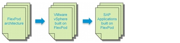
The SAP applications built on FlexPod data center solution introduces an infrastructure that is based on virtualization technologies on all layers of the solution stack within a pool of shared resources. SAP applications can be run on VMware virtual machines as well as on bare-metal servers. Figure 2 shows the components that are included.
Figure 2 Technology components of SAP applications built on FlexPod
The current version of the FlexPod data center solution supports SAP applications that run on SuSE Linux® or Red Hat Enterprise Linux using the Oracle® Database.
Management Components
SAP applications built on FlexPod includes the following management software components from the different partners:
•
–
•
–
•
–
•
•
–
–
–
–
–
Tenant Operational Modes
SAP applications built on FlexPod is based on a multi-tenancy concept. A tenant is defined as a set of standardized, virtualized resources taken from a shared pool. Each tenant is isolated by VLAN technology on the networking and by NetApp vFiler® technology on the storage layer. SAP applications built on FlexPod consists of at least two tenants, one infrastructure tenant and one tenant for all SAP applications. Additional tenants can be created based on multi-tenancy requirements; for example, isolation of subsidiaries or isolation of clients. Additional tenants are also used to cover specific use cases such as fenced clones of SAP systems or landscapes.
The infrastructure tenant is used to run all management components for the infrastructure and the application layer. All "managed tenants" are administered from the infrastructure tenant.
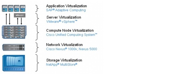
Figure 3 shows how an SAP landscape is deployed with a single managed tenant. All SAP systems are running within this tenant (Managed Tenant 1).
Figure 3 SAP applications built on FlexPod with a single tenant
Figure 4 shows multiple tenants.
Figure 4 SAP application built on FlexPod with multiple tenants

Single-Managed Tenant Operation
Figure 5 shows a single-tenant environment.
Figure 5 Single-tenant operation
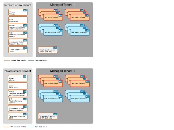
The SAP systems can run on VMware virtual machines or on bare-metal servers. All management applications are installed within the infrastructure tenant. These management applications run on VMware virtual machines.
•
•
•
•
•
In the second tenant, all SAP applications are running. The SAP systems can either run on VMware virtual machines or on bare-metal servers.
The "tenant-specific services" are also running in a VMware virtual machine in the second tenant, providing Dynamic Host Configuration Protocol (DHCP), Domain Name System (DNS), and Network Information Service (NIS) for this tenant.
Multiple Managed Tenant Operation
Figure 6 shows multiple tenants can be used to isolate different subsidiaries, clients, or specific SAP landscapes.
Figure 6 Multiple tenants
When multiple tenants are used, the "tenant-specific services" VM runs in every tenant.
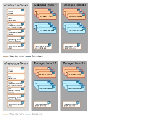
Server Architecture
Cisco Unified Computing System
The Cisco Unified Computing System physical servers are completely stateless and interchangeable. All server, network, and storage configuration information is contained in predefined XML service profiles, stored in the central Cisco UCS Manager, which dynamically maps these service profiles to physical compute blades based on predefined resource pools and policies. SAP administrators can bring new computing resources online and replicate or repurpose them in a matter of minutes rather than the weeks or months it traditionally takes to procure and deploy new resources.
The main system components include:
Compute. The system is based on an entirely new class of computing system that incorporates blade servers based on Intel® Xeon® processors. The Cisco UCS blade servers offer patented Cisco Extended Memory Technology to support applications with large datasets and allow more virtual machines per server.
Network. The system is integrated onto a low-latency, lossless, 10Gb/sec unified network fabric. This network foundation consolidates what today are three separate networks: LANs, SANs, and high-performance computing networks. The unified fabric lowers costs by reducing the number of network adapters, switches, and cables and by decreasing power and cooling requirements.
Virtualization. The system unleashes the full potential of virtualization by enhancing the scalability, performance, and operational control of virtual environments. Cisco security, policy enforcement, and diagnostic features are now extended into virtualized environments to better support changing business and IT requirements.
Storage access. The system provides consolidated access to both SAN storage and network-attached storage (NAS) over the unified fabric. Unifying storage access means that the Cisco Unified Computing System can access storage over Ethernet, Fibre Channel, Fibre Channel over Ethernet (FCoE), and iSCSI, providing customers with choice and investment protection. In addition, administrators can preassign storage-access policies for system connectivity to storage resources, simplifying storage connectivity and management while helping increase productivity.
Management. The system uniquely integrates all the system components, enabling the entire solution to be managed as a single entity through the Cisco UCS Manager software. The Cisco UCS Manager provides an intuitive graphical user interface (GUI), a command line interface (CLI), and a robust application programming interface (API) to manage all system configuration and operations. The Cisco UCS Manager helps increase IT staff productivity, enabling storage, network, and server administrators to collaborate on defining service profiles for applications. Service profiles are logical representations of desired physical configurations and infrastructure policies. They help automate provisioning and increase business agility, allowing data center managers to provision resources in minutes instead of days.
Working as a single, cohesive system, these components unify technology in the data center. They represent a radical simplification in comparison to traditional systems, helping simplify data center operations while reducing power and cooling requirements. The system amplifies IT agility for improved business outcomes. The Cisco Unified Computing System components illustrated in Figure 7 include, from left to right, fabric interconnects, blade server chassis, blade servers, and in the foreground, fabric extenders and network adapters.
Figure 7 Cisco Unified Computing System
VMware Architecture
VMware vSphere
VMware vSphere provides a foundation for virtual environments, including clouds. In addition to the hypervisor itself, it provides tools, such as VMware VMotion®, to manage the virtual landscape, and it allows the creation of secure private landscapes. With VMotion, you can move a virtual machine from one physical compute node to another without service interruption.
The powerful VMware virtualization solution enables you to pool server and desktop resources and dynamically allocate them with service-level automation so you can deploy a private cloud and deliver IT as a service (ITaaS). VMware components provide a scalable approach to virtualization that delivers high availability and agility to meet your changing business requirements. VMware vSphere, the industry's most complete and robust virtualization platform, increases IT efficiency through consolidation and automation, dramatically reducing your capital and operating costs while giving you the freedom to choose your applications, OS, and hardware. VMware vCenter Server Standard offers proactive end-to-end centralized management of virtual environments, delivering the visibility and responsiveness you need for cloud-ready applications.
VMware Network Distributed Switch
VMware vNetwork Distributed Switch maintains network runtime state for VMs as they move across multiple hosts, enabling inline monitoring and centralized firewall services. It provides a framework for monitoring and maintaining the security of virtual machines as they move from physical server to physical server and enables the use of third-party virtual switches such as the Cisco Nexus 1000V to extend familiar physical network features and controls to virtual networks.
In combination with a Cisco Virtual Interface Card (VIC) such as the Cisco UCS M81KR Virtual Interface Card, the Cisco UCS Virtual Machine Fabric Extender (VM-FEX) can be used to connect and manage the VMware vNetwork Distributed Switch directly. Using the Cisco UCS Manager, VM-FEX instead of a Cisco Nexus 1000V will shift the management from a "network device" to the UCS Manager by keeping all the advantages of a distributed switch as discussed in section, "Network Architecture."
Throughout this document Cisco Nexus 1000V will be used for all examples. Appendix D will discuss the configuration of a distributed switches based on VM-FEX.
Figure 8 shows the VMware components and the plug-in architecture for VMware vCenter Server, which enables you to integrate additional plug-ins from NetApp and Cisco to manage integrated landscapes.
Figure 8 Overview of VMware components and management plug-ins

Storage Architecture
SAP applications built on FlexPod uses the NetApp MultiStore® software, which lets you quickly and easily create discrete and private logical partitions on a single storage system. Each virtual storage partition, a vFiler secure partition, maintains separation from every other storage partition, so you can enable multiple tenants to share the same storage resource without compromising privacy or security.
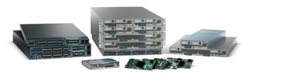
Infrastructure Tenant
The infrastructure tenant is used to run all management components for the infrastructure and the application layer. All "managed tenants" are administered from the infrastructure tenant. This tenant has at least two vFiler units, one primary and one backup. An additional software vFiler secure partition is available, which can be accessed (read/writable) from the infrastructure tenant and (read-only) from managed tenants. The software vFiler unit is used to distribute software and scripts to the managed tenants for automation purposes.
Figure 9 shows an example configuration with two FAS HA pairs located in different data centers. A FAS HA pair consists of two storage controllers in a high-availability configuration.
Each storage controller is assigned to a resource pool in NetApp Provisioning Manager, and vFiler units can be provisioned to each resource pool. In the example, resource pool 2 and resource pool 4 are resource pools that have SAS and SATA drives and are therefore used for both primary and backup vFiler units. The other resource pools are mainly used for primary vFiler units. The software vFiler unit is located at the first resource pool.
Figure 9 vFiler configuration infrastructure tenant

The infrastructure tenant has two central NetApp FlexVol® volumes that are shared with all systems running in this tenant:
•
–
–
–
•
–
–
The volumes Share and Backup are mounted by all systems.
In addition, several other volumes are part of the infrastructure tenant:
•
–
–
–
•
–
–
•
–
–
–
•
–
•
–
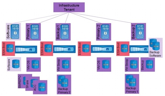
The boot LUNs for the VMware ESXi and bare metal server must be configured on the physical controllers. All physical storage controllers can host volumes with boot LUNs. However, the LUNs should be located in the same data center as the servers that boot using these LUNs.
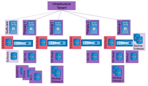
Figure 10 is an overview of the distribution of volumes to vFiler units and controllers.
Figure 10 Overview of infrastructure tenant volumes
Managed Tenants
Figure 11 shows an example configuration with two FAS HA pairs located in different data centers. Each storage controller is assigned to a resource pool in NetApp Provisioning Manager, and vFiler units can be provisioned to each resource pool. In the example, resource pool 2 and resource pool 4 are resource pools that have SAS and SATA drives and are therefore used for primary and backup vFiler units. The other resource pools are used for primary vFiler units. With SAP applications built on FlexPod, the vFiler units are configured as follows:
•
–
–
•
–
–
Figure 11 vFiler unit configuration for a tenant

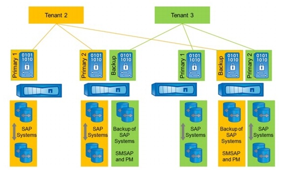
Figure 12 shows an example configuration with three managed tenants. The primary vFiler units are distributed to different resource pools. The backup vFiler units are configured at the backup resource pool in the other data center so that backups of primary data are located in a different data center.
Figure 12 vFiler unit configuration for multiple tenants

Each tenant has two central FlexVol volumes that are shared with all SAP systems running in that tenant.
•
–
–
–
•
•
–
•
The volumes Share and Backup are mounted by all operating systems during system boot. Figure 13 shows the central volumes of a single tenant.
Figure 13 Central volumes of a tenant

An additional tenant necessitates an additional central volume Backup on the Backup vFiler unit of the tenant and an additional Share volume assigned to the Primary1 vFiler unit of that tenant. Figure 14 shows the central volume configuration with two managed tenants.
Figure 14 Central volumes with multiple tenants

During the process of provisioning storage volumes for an SAP system, you can decide on which primary vFiler unit the SAP system should run. This allows different SAP systems to run on different storage hardware. Each SAP system consists of two volumes, the sapdata and the saplog volumes. Backups of SAP systems are controlled by SnapManager for SAP and NetApp OnCommand® Unified Manager. The backups are stored on the backup vFiler unit of each tenant. When an SAP system copy has finished using SnapManager for SAP, the clone of the sapdata volume can be either on the same primary vFiler unit as the source system or on the backup vFiler unit. Figure 15 shows an example distribution of SAP volumes.
Figure 15 SAP volumes of a tenant

With additional tenants, the FlexVol volumes for the SAP systems of the new tenant are assigned to the primary vFiler units of the tenant. Figure 16 shows an example configuration.
Figure 16 SAP volumes with mulitple tenants
Examples of Storage Service Levels
Based on resource pools, provisioning policies, and protection policies, different storage service levels can be offered by NetApp Operations Manager, Protection Manager, and Provisioning Manager.
A resource pool can consist of several physical controllers and aggregates. However, with SAP applications built on FlexPod, each resource pool should contain only one controller. The controller and aggregates of one resource pool are used to provision storage units such as vFiler units, volumes, and qtrees.
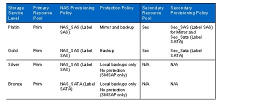
A provision policy defines, based on several criteria, which physical storage is used for provisioning storage. Criteria are RAID protection levels, deduplication, HA configuration of the storage system, and other factors.
Two kinds of provisioning policies are used in FlexPod: NAS and secondary. A NAS provision policy is used for primary storage and can also be used for mirror destinations. A secondary provisioning policy is used for backup purposes and can also be used for mirror destinations.
A protection policy defines the way in which the primary data is protected. A mirror protection policy is used mainly for DR purposes (1:1 source:destination); a backup policy is used for backup purposes (1:N relationship).
Labels can be assigned to different physical storage objects like controllers and aggregates. These labels can be set in a provisioning policy, for example to make sure that the right aggregate is used.
Table 1 shows four different storage service levels: Platin, Gold, Silver, and Bronze. Each service level includes a resource pool, a NAS provisioning policy, and a protection policy. In addition, a secondary resource pool and secondary provisioning policy are needed for Platin and Gold levels.
Table 1 Storage service levels
Notes
•
•
•
•
•
•
•
•
For more information, refer to "Provisioning Manager and Protection Manager Guide to Common Workflows for Administrators for Use with DataFabric Manager Server 4.0."
Integrated Storage-Based Backup
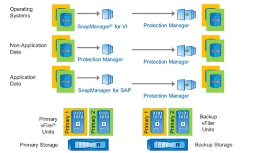
SAP applications built on FlexPod has an integrated backup solution for all infrastructure and application data. Nonapplication data is backed up by using Protection Manager. All storage volumes are provisioned with Provisioning Manager and are automatically assigned to a protection policy.
Virtual machines and templates are backed up with SnapManager for Virtual Infrastructure (SMVI), which is part of the NetApp Virtual Storage Console (VSC). SMVI integrates with VMware vSphere and provides consistent storage of Snapshot images of individual VMs or complete datastores. These consistent Snapshot images are replicated to a secondary storage system through Protection Manager.
SAP application data is backed up with SnapManager for SAP and Protection Manager, offering a Backint integration into SAP Br*tools.
The integrated storage-based backup offers these benefits:
•
•
•
•
•
Figure 17 is an overview of the backup solution.
Figure 17 Overview of integrated backup
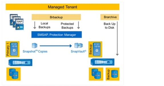
SnapManager for SAP offers Backint integration into SAP Br*tools. Backup and restore processes are executed with SAP Brbackup, Brrachive, Brrecover, and Brrestore.
Backups executed by Brbackup can be done as either local or protected backups.
•
•
Local backups are typically created more than once a day and are kept for 3 to 5 days at the primary storage. Protected backups are typically created once a day and are kept for 2 to 4 weeks at the secondary storage. Backup schedules and retention policies can be configured individually with the SAP database planning calendar, SnapManager for SAP, and Protection Manager.
Archive log backups are made using Brarchive. Brarchive is configured to back up the archive logs directly to the backup volume on the secondary storage system. Figure 18 shows the backup process of SAP systems.
Figure 18 Integrated backup of SAP systems
Network Architecture
Cisco Nexus 5000 Series Switches
The Cisco Nexus 5000 Series switches, part of the Cisco Nexus family of data-center-class switches, delivers an innovative architecture to simplify data center transformation by enabling a high-performance, standards-based, Ethernet unified fabric. The platform consolidates separate LAN, SAN, and server cluster network environments into a single unified fabric. Backed by a broad system of industry-leading technology partners, the Cisco Nexus 5000 Series is designed to meet the challenges of next-generation data centers, including dense multisocket, multicore, virtual-machine-optimized services, in which infrastructure sprawl and increasingly demanding workloads are commonplace.
Cisco Nexus 1000V Series Switches
The Cisco Nexus 1000V Series provides a common management model for both physical and virtual network infrastructures through Cisco VN-Link technology, which includes policy-based virtual machine connectivity, mobility of virtual machine security and network properties, and a nondisruptive operational model.
Policy-Based Virtual Machine Connectivity
To facilitate easy creation and provisioning of virtual machines, the Cisco Nexus 1000V Series includes port profiles. Port profiles enable you to define virtual machine network policies for different types or classes of virtual machines and then apply the profiles through VMware vCenter. Port profiles are a scalable mechanism for configuring networks with large numbers of virtual machines. When the port profiles include QoS and security policies, they constitute a complete service-level agreement (SLA) for the virtual machine's traffic.
Mobility of Virtual Machine Security and Network Properties
Network and security policies defined in the port profile follow the virtual machine throughout its lifecycle, whether it is being migrated from one server to another, suspended, hibernated, or restarted. In addition to migrating the policy, the Cisco Nexus 1000V Series VSM moves the virtual machine's network state. Virtual machines participating in traffic-monitoring activities can continue these activities uninterrupted by VMware VMotion operations. When a specific port profile is updated, the Cisco Nexus 1000V Series automatically provides live updates to all the virtual ports that use that same port profile. The capability to migrate network and security policies through VMware VMotion makes regulatory compliance much easier to enforce with the Cisco Nexus 1000V Series because the security policy is defined in the same way as for physical servers and is constantly enforced by the switch.
Example Network Architecture
Putting it all together, this example shows how all the required physical components must be attached to the networking layer:
•
•
•
•
•
•
In order to focus on the network essentials, this example does not include any FC or FCoE connectivity, nor does it detail HA setup on the Cisco Nexus Switch layer. It includes only one NetApp cluster; that is, two physical control nodes.
To illustrate the tenant-based structure, this example uses a total of three tenants: one infrastructure tenant and two tenants (t002, t003) to run independent SAP landscapes.
In this example, all physical components are connected to a physical management switch because this configuration is found in most customer data centers for the physical or console LAN.
As shown in Figure 19, four blades are used in such a way that:
•
•
Figure 19 Example network—physical layer
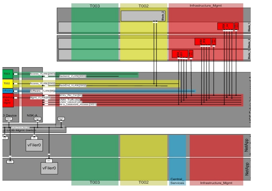
For each IP network, a VLAN is defined that separates the different networks on layer 2. The networks can be grouped into three logical segments:
•
–
–
–
–
–
•
–
–
•
–
–
All the VLANs are connected to the Cisco Nexus 5000 Series switch and are defined at the UCS uplink; the physical storage controllers only define interfaces on the physical management LAN.
Each virtual or physical host in a tenant, except for the special infrastructure tenant, is connected to two networks:
•
•
As shown in Figure 20, the vFiler units are only connected to the back-end VLAN
Routing
In order to reach the Access VLAN from the customer network and for all internal management connections between the infrastructure management VLAN and the Tenant Access LAN's, the solution requires that routing into this VLAN's is possible..
The previous version of this guide describes the connection of the FlexPod Infrastructure to a central switch to use the required L3 functionality to enable routing. Now, as an additional option the L3 modules of both Cisco Nexus 5548 switches could be used to implement the required L3 functionality. All examples throughout this document are using the central switch configuration, while an alternative setup using the Cisco Nexus 5548 L3-modules is described in Appendix E.
For the tenant access VLANs and the infrastructure management VLAN only, a switch virtual interface (SVI) is defined on the central switch The SVI offers the capability of basic layer 3 routing functionality on a layer 2 switch without the requirement of specific routing protocols in order to implement inter-VLAN routing.
Layer 3 separation of the tenants is accomplished by defining ACLs on the central, so that all security and connectivity requirements can be adapted through standard or extended ACLs. ACLs must be defined so that communication between the individual tenants (t002, t003) is prohibited, while communication between the infrastructure tenant and the individual tenants must be possible in order to allow management functions to work.
ACLs can also be used to control the accessibility of the systems in a tenant from the client network. For more information about ACLs, see section 4, "FlexPod Built on VMware Setup."
Figure 20 Example network—virtual systems view

Application and Data Mobility
SAP applications built on FlexPod provides mobility on all layers of the solution stack:
•
•
•
•
These technologies are used for migrating applications and data with little or no downtime; they support the following use cases:
•
–
–
–
•
–
•
–
Automated Provisioning of Infrastructure Components
SAP applications built on FlexPod offers the possibility of automatically provisioning infrastructure components, such as the creation of new tenants and the deployment of operating systems based on templates.
Tenant Provisioning
All managed tenants in the SAP applications built on FlexPod solution are based on the same components, combined with tenant-specific parameters. This standardization allows you to document and automate the workflow for the provisioning and deprovisioning of additional tenants.
A tenant is provisioned with the following configuration steps:
•
–
•
–
–
•
–
–
•
–
–
Figure 21 shows an overview of tenant components.
Figure 21 Overview of tenant components

Operating System Deployment
The combination of NetApp cloning technology, templates of operating systems, and virtualized applications with SAP Adaptive Computing allows fast provisioning of operating systems for new servers and virtual machines and simplifies patching of operating systems.
New patches are applied and tested at a new golden image. After that the image gets cloned and, in combination with VMware vSphere and the Cisco UCS, is provisioned to new servers (physical or virtual), and the SAP application is relocated to the new hosts.
All required services for operating an SAP system (for example, backup services) are preinstalled and are automatically configured during the operating system provisioning process. This reduces the amount of time and resources required to apply patches to operating systems, because only one operating system must be patched and tested and not the operating systems of all involved hosts.
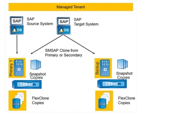
Automated Space-Efficient SAP System Copies
SAP applications built on FlexPod leverages SnapManager for SAP to create space-efficient SAP system copies. Any backup that has been created with SMSAP can be used as a source for an SAP system copy. The target storage of the system copy can be either the primary or the backup vFiler unit. The source and the target SAP systems must be in the same tenant.
The following use cases are supported with SAP applications built on FlexPod:
•
•
Figure 22 shows the process for automated space-efficient SAP system copies.
Figure 22 Automated SAP system copies
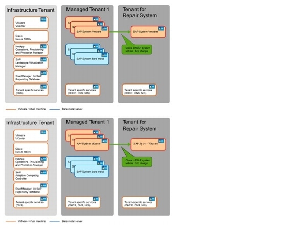
Provisioning Fenced SAP Systems
The built-in secure multi-tenancy functionality of SAP applications built on FlexPod is also used to cover specific use cases that require isolation of an SAP system.
A fenced SAP system is an identical 1:1 clone of an SAP source system and can therefore be created in a few minutes. The clone has the same SID as the source system. With the standard approach, the target system has a different IP address and a different fully qualified domain name (FQDN). Both attributes are tenant specific.
For example:
Source system: SID=PE6, source tenant=t002, hostname=cipe6.t002.company.corp, IP=192.168.2.100
Target system: SID=PE6, target tenant=t003, hostname=cipe6.t003.company.corp, IP=192.168.3.100
One use case, shown in Figure 23, is the creation of a repair system that can be used to address logical errors that occurred in the source system.
Figure 23 Multiple tenants including a repair system
SAP applications built on FlexPod includes a fully automated workflow for creating a repair system:
1.
2.
3.
4.
5.
6.
Provisioning of complete fenced SAP landscapes requires additional steps, which are described in section, "Cloning a Complete System Landscape."
System Scalability
Over time, the application and business demands for a customer implementation may grow and additional storage or compute capabilities may be required. In a standard implementation, adding resources to an existing environment presents some challenges for the IT team that may not be easy to handle in a highly demanding and business-critical application stack such as SAP.
SAP applications built on FlexPod is designed to be as scalable as possible. This is true for the base components such as compute, network, and storage, and also for the design and related software solutions that support this scalability.
Scalability-in all the different directions-is a very complex and customer-specific process. However, this section outlines some basic principles that you can use to meet the demands of growth and scalability.
Extending Additional Storage
Additional storage may be necessary due to additional space requirements, which are often correlated with increased I/O demands on the storage controller.
The requirement for additional storage can be easily solved by adding shelves to the existing controllers, and the requirement for additional space can be solved by adding storage systems. SAP applications built on FlexPod is built with all equipment connected to Cisco Nexus 5000 switches, which typically provides more than enough bandwidth so that the new storage can easily be added by using spare ports.
Because all customer projects use vFiler units, these units can easily be moved to the new storage systems without a major impact on operations.
Extending Additional Compute Resources
Applications such as SAP often require additional compute resources. This need might be due to enhanced functionality added over time, or it might be due to an increase in the number of users to the system, which requires more CPU and memory. Because SAP is a highly flexible architecture, most of these demands can be met by simply adding application servers and thus making use of SAP's 3-tier architecture.
Other demands require additional memory and CPU for an existing SAP instance. Because SAP applications built on FlexPod uses VMware for virtualization and can also integrate physical blades as compute resources, these demands can typically be met by changing VMware's CPU and memory assignment to the virtual machine. The architecture and implementation of SAP applications built on FlexPod uses adaptive enabled SAP installations, so assigning additional resources is as simple as stopping an SAP instance on one system such as a virtual machine and restarting it on another system such as a physical blade. After some modifications to the SAP profile, the relocated SAP instance uses the additional resources.
All of these scalability features are incorporated into the solution design. But at some point, you may need to physically add compute resources to the infrastructure in order to meet application demands. This is as easy as adding storage. For example, an additional chassis with slots for additional blades can easily be added to a Cisco UCS Fabric Interconnect. After configuring this new server, the added compute power can be used by applying the Cisco UCS service profiles, allowing you to move an existing server definition to the added blades and to use not only the additional hardware, but also the increased amount of memory or CPU power.
To implement all of these changes, only minimal modifications need to be made to the configuration, with only minimal disruption of the business applications, such as restarting an SAP system.
Adding a Second FlexPod Infrastructure
Some customers want to grow linearly by adding storage and compute power to an existing environment, and they might also consider adding a complete FlexPod infrastructure to a second server room and want to understand how to optimize the efficiency of these additional resources.
This setup is often discussed with additional requirements for high availability and disaster recovery. These topics will be covered in detail in a later release of SAP applications built on FlexPod; this subsection describes only a simple, generic application of this infrastructure. Typically, only a customer-specific project can describe in detail all requirements and demands.
One way to add a complete FlexPod infrastructure (storage, compute, Cisco UCS, and Cisco Nexus) and use it for application demands, while avoiding additional overhead due to duplicate management and/or infrastructure components, is to simply connect the additional components on a pure networking basis through a layer 2 connection to the central switch. There are many different ways of doing this, but at a high level the tasks are as follows:
•
–
–
•
–
–
–
–
As a result of this setup, all the new infrastructure resources can be used almost nondisruptively while using the same management components. The design and the scripts are intended to work even in such an extended environment. Of course, the disadvantage of this example is that a lot of networking traffic is routed over the central switch.
Overview of Solution Setup and Operation
This section is an overview of the tasks and workflows for setting up and operating SAP applications built on FlexPod.
Infrastructure Setup Tasks
1.
2.
3.
a.
b.
c.
d.
e.
f.
g.
4.
a.
b.
5.
a.
b.
c.
Operational Tasks
1.
a.
b.
c.
2.
3.
a.
b.
4.
a.
b.
c.
d.
5.
6.
7.
a.
b.
8.
FlexPod Built on VMware Setup
The first step in setting up SAP Applications built on FlexPod is to set up FlexPod for VMware according to TR-3939: VMware vSphere Built on FlexPod Implementation Guide. The following sections describe only the differences and additional tasks required.
Changes Compared to FlexPod Built on VMware
Before setting up the system according to TR-3939, refer to the "SAP Applications built on FlexPod Technical Specifications" guide for the software version used.
NetApp Operations Manager (Version 5.1) is installed on a Linux VM instead of on a Windows® VM. The configuration steps are the same (refer to section 3.12 of TR-3939).
The NetApp Virtual Storage Console is installed on the Windows vCenter VM instead of on a new Windows VM (section 3.11 of TR-3939). You must add a second network card to the vCenter VM connected to the Network File System (NFS) network.
Because the Rapid Cloning Utility is used to deploy new VMs, in TR 3939, do not execute step 3, section 3.2, subsection "Creating the necessary infrastructure volumes." (3. Type sis on /vol/infrastructure.)
DNS has to be setup also for the infrastructure vFiler® units. Therefore setup the DNS settings by entering yes within step 6 in TR 3939, section 3.2, subsection "Creating the infrastructure vFiler units" at both controllers. Use the DNS server IP address of the infrastructure tenant DNS server and its DNS Domain name for the backend network.
Every application other than the management components runs in additional managed tenants and not in the infrastructure tenant
Additional Storage Configuration
For additional configuration, log in to controller A and set the following option:
options vfiler.vol_clone_zapi_allow on
Also, set this option on controller B.
Create a new VLAN for NDMP traffic, and configure SnapVault® and SnapMirror® access on each controller.
Log in to controller A and execute the following commands:
vlan add vif0 "var_ndmp_vlan_id"
wrfile -a /etc/rc "vlan add vif0 "var_ndmp_vlan_id""
ifconfig vif0-"var_ndmp_vlan_id" mtusize 9000
wrfile -a /etc/rc "ifconfig vif0-"var_ndmp_vlan_id" mtusize 9000"
ifconfig vif0-"var_ndmp_vlan_id" partner vif0-"var_ndmp_vlan_id"
wrfile -a /etc/rc "ifconfig vif0-"var_ndmp_vlan_id" partner vif0-"var_ndmp_vlan_id""
ifconfig vif0-"var_ndmp_vlan_id" "var_ndmp_ip_contr_a" netmask "var_ndmp_netmask"
wrfile -a /etc/rc "ifconfig vif0-"var_ndmp_vlan_id" "var_ndmp_ip_contr_a" netmask "var_ndmp_netmask""
options ndmpd.preferred_interface vif0-"var_ndmp_vlan_id"
wrfile -a /etc/snapmirror.allow ""var_ntap_B_hostname""
wrfile -a /etc/snapmirror.allow ""var_ndmp_ip_contr_b""
options snapvault.access host="var_ntap_B_hostname","var_ndmp_ip_contr_b"
options snapvault.enable on
options snapmirror.enable on
ndmpd on
vfiler limit 65
Log in to controller B and execute the following commands:
vlan add vif0 "var_ndmp_vlan_id"
wrfile -a /etc/rc "vlan add vif0 "var_ndmp_vlan_id""
ifconfig vif0-"var_ndmp_vlan_id" mtusize 9000
wrfile -a /etc/rc "ifconfig vif0-"var_ndmp_vlan_id" mtusize 9000"
ifconfig vif0-"var_ndmp_vlan_id" partner vif0-"var_ndmp_vlan_id"
wrfile -a /etc/rc "ifconfig vif0-"var_ndmp_vlan_id" partner vif0-"var_ndmp_vlan_id""
ifconfig vif0-"var_ndmp_vlan_id" "var_ndmp_ip_contr_b" netmask "var_ndmp_netmask"
wrfile -a /etc/rc "ifconfig vif0-"var_ndmp_vlan_id" "var_ndmp_ip_contr_b" netmask "var_ndmp_netmask""
options ndmpd.preferred_interface vif0-"var_ndmp_vlan_id"
wrfile -a /etc/snapmirror.allow ""var_ntap_A_hostname""
wrfile -a /etc/snapmirror.allow ""var_ndmp_ip_contr_a""
options snapvault.access host="var_ntap_A_hostname","var_ndmp_ip_contr_a"
options snapvault.enable on
options snapmirror.enable on
ndmpd on
vfiler limit 65
Additional Network Configuration
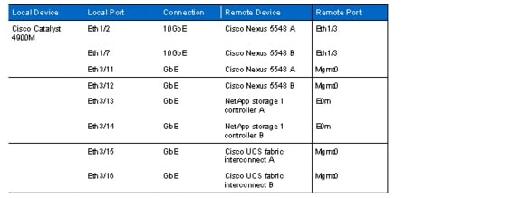
Management Network for Physical Components
In the FlexPod built on VMware documentation, the management ports of the components are connected to port "any." For the SAP applications built on FlexPod data center solution, detailed documentation of the management ports and the routing between all components is required. Table 2 documents a sample configuration with an additional Cisco Catalyst® switch representing the customer data center network. The Cisco Catalyst switch is not part of the solution.
Table 2 Cisco Catalyst 4900M Ethernet cabling information
1.
EnableConf terminalinterface TenGigabitEthernet1/2description "var_nexus_A_hostname":Eth1/3switchport trunk native vlan "var_global_mgmt_vlan_id"switchport trunk allowed vlan "var_global_mgmt_vlan_id","var_physmgmt_vlan_id"switchport mode trunkno shutdowninterface TenGigabitEthernet1/7description "var_nexus_B_hostname":Eth1/3switchport trunk native vlan "var_global_mgmt_vlan_id"switchport trunk allowed vlan "var_global_mgmt_vlan_id","var_physmgmt_vlan_id"switchport mode trunkno shutdowninterface GigabitEthernet3/11description "var_nexus_A_hostname":mgmtswitchport access vlan "var_global_mgmt_vlan_id"switchport mode accessno shutdowninterface GigabitEthernet3/12description "var_nexus_B_hostname":mgmtswitchport access vlan "var_global_mgmt_vlan_id"switchport mode accessno shutdowninterface GigabitEthernet3/13description "var_ntap_A_hostname":e0mswitchport access vlan"var_global_mgmt_vlan_id"switchport mode accessno shutdowninterface GigabitEthernet3/14description "var_ntap_B_hostname":e0mswitchport access vlan "var_global_mgmt_vlan_id"switchport mode accessno shutdowninterface GigabitEthernet3/15description "var_ucsm_A_hostname":mgmtswitchport access vlan "var_global_mgmt_vlan_id"switchport mode accessno shutdowninterface GigabitEthernet3/16description "var_ucsm_B_hostname":mgmtswitchport access vlan "var_global_mgmt_vlan_id"switchport mode accessno shutdownexitexitcopy run startexit2.
Conf terminalinterface port-channel100description cat4900switchport mode trunkswitchport trunk native vlan "var_global_mgmt_vlan_id"switchport trunk allowed vlan "var_global_mgmt_vlan_id","var_physmgmt_vlan_id"spanning-tree port type networkvpc 100exitinterface Ethernet1/3description cat4900:Eth1/2channel-group 100 mode activeno shutdownexitcopy run startexit3.
Conf terminalinterface port-channel100description cat4900switchport mode trunkswitchport trunk native vlan "var_global_mgmt_vlan_id"switchport trunk allowed vlan "var_global_mgmt_vlan_id","var_physmgmt_vlan_id"spanning-tree port type networkvpc 100exitinterface Ethernet1/3description cat4900:Eth1/7channel-group 100 mode activeno shutdownexitcopy run startexitNDMP—Traffic Network
The NDMP-traffic network is used for data transfer from NetApp storage to NetApp storage.
The NDMP-traffic VLAN is required only between the storage controllers within a FlexPod solution; therefore the VLAN ID is configured only on the Cisco Nexus 5548 and storage devices.
1.
Conf terminalvlan "var_ndmp_vlan_id"name NDMP-VLANexitinterface Vlan "var_ndmp_vlan_id"no shutdownip address <<var_ndmp_network>> "var_ndmp_netmask"exitinterface port-channel11switchport trunk allowed vlan add "var_ndmp_vlan_id"exitinterface port-channel12switchport trunk allowed vlan add <"var_ndmp_vlan_id"exitexitcopy run startexitThe NDMP-traffic network is not routed in our configuration; therefore we do not configure inter-VLAN routing on the Cisco Catalyst 4900 and do not allow the VLAN ID on the port channel 100.
Central Software Share Network
The central software repository is used to store configuration files, installation images, and additional software components. A dedicated network segment is used to access the central software share.
1.
Conf terminalvlan "var_software_vlan_id"name CentralSWexitinterface Vlan "var_software_vlan_id"no shutdownexitinterface port-channel11switchport trunk allowed vlan add "var_software_vlan_id"exitinterface port-channel12switchport trunk allowed vlan add "var_software_vlan_id"exitexitcopy run startexit2.
EnableConf terminalvlan "var_software_vlan_id"name CentralSWexitinterface Vlan"var_software_vlan_id"ip address "var_software_gw_addr" "var_software_netmask"no shutdownexitinterface TenGigabitEthernet1/2switchport trunk allowed vlan "var_software_vlan_id"exitinterface TenGigabitEthernet1/7switchport trunk allowed vlan "var_software_vlan_id"exitcopy run startexitInter-VLAN Routing
The FlexPod environment forces an introduction of predefined access rules in order to implement a strict separation of the different tenants combined with specific access rights to the generally available services.
In the first step, standard access lists are implemented that match only on IP network prefixes, to separate the networks and to define on a low granular layer the basic access rights. In the next step, access lists are defined with a focus on the application layer, and therefore extended access lists must be used.
A VLAN is defined for each tenant IP network, which separates the different networks on layer 2. Each VLAN is configured on the central switch with a switch virtual interface (SVI). That interface represents a logical layer 3 interface on a switch and is bound to a specific VLAN. The SVI offers the capability of basic layer 3 routing functionality on a layer 2 switch without the requirement of specific routing protocols in order to implement inter-VLAN routing.
The following items define the access rights:
•
•
•
•
In order to define the VLANs, connect the switches, and define the SVIs, the following generic command sequence must be followed.
On the central switch only, add the missing VLANs (the Nexus switches already have all required VLANs defined):
vlan VLANIDname VLANNAMEOn all of the required switches, add the VLANs to the appropriate ports and portchannels that are used to interconnect the central switch with the Nexus 5548 switches by issuing the following command for each channel:
Interface PORTCHANNEL/PORT_NAMEswitchport trunk allowed vlan add VLANIDOn the central switch only, define the SVIs for all routed VLANs:
interface VLANIDip address VLAN_GATEWAY_IP VLAN_NETMASKno shutdownexitAccess Lists Basics
Named access lists are defined on a router layer and can be applied to all networking interfaces where an IP address has been defined. In this case, this is on the VLAN interfaces defined on the layer 3 device (the Catalyst switch).
Access lists can be defined as standard or extended lists, depending on the filtering requirements. Standard lists define only the source and target host where the traffic should be permitted or denied; extended lists have the flexibility to define much more granular filtering, down to the communication port level.
Command syntax for a standard list:
access?list access?list?namepermit|deny {host|source source?wildcard|any}Command syntax for an extended list:ip access?list extended namepermit|deny [protocol] {source source?wildcard|any} {destination destination?wildcard|any} [precedence precedence][tos tos][established] [log|log?input] [operator destination?port|destination port]For a detailed discussion of ACLs, consult the Cisco documentation.
Example ACLs for SAP Applications Built on FlexPod
The examples in this document focus on standard FlexPod communication needs between defined networks. Examples use the following numbering rules:
•
•
•
All examples are based on these numbers and must be adapted according to the user networks and additional customer requirements.
Every tenant must have access to services in the infrastructure tenant and to the software share. For this, a standard access list can be used on the tenant access VLAN interface to allow only these networks to have access to the tenant. The command is:
Access-list VLAN2002permit 192.168.2.0 0.0.0.255permit 192.168.96.0 0.0.0.255permit 192.168.99.0 0.0.0.255deny anyTo activate this access list on the tenant VLAN, the VLAN definition command on the Catalyst switch must be extended. The complete interface definition looks like this:
interface Vlan2002ip address 192.168.2.1 255.255.255.0ip access-group Vlan2002 inip access-group Vlan2002 outTo restrict access to the infrastructure services, a detailed look at the communication requirements is necessary and an extended access control list (ACL) should be used.
Figure 24 shows the network ports that are used by the NetApp storage management products.
Figure 24 Overview of network ports for NetApp storage management

Between a managed tenant (Tenant 2 in Figure 24) and the infrastructure tenant, the following ports are used by SnapDrive®, SnapManager, Operations Manager, or Protection Manager, and the SnapManager for SAP (SMSAP) GUI:
NetApp SnapDrive for UNIX® running on each host in the managed tenants:
•
–
•
–
SMSAP server running on each host in the managed tenants:
•
–
•
–
Inbound traffic to the infrastructure tenant is on port 1521, port 8488, and port 8088.
Between the infrastructure tenant and the physical management network, the following network ports are used by Operations Manager to communicate with the storage controllers.
•
–
•
–
The only inbound traffic is on port 162. However, the sample configuration allows all traffic from the physical management network into the infrastructure tenant.
In addition to the NetApp communication requirements, DNS communication between the Master DNS in the infrastructure tenant and the DNS servers in the managed tenants must be allowed.
To be able to access the infrastructure tenant from outside, additional ports must be configured; for example, SSH (port 22), HTTPS (port 443), or RDP (port 3289).
This sample defines the outgoing traffic at the SVI on the management network. The router sends packages to destinations in the management network if the following rules apply:
ip access-list extended Vlan99OUTpermit tcp <admin station network> eq 22 anypermit tcp <admin station network> eq 443 anypermit tcp <admin station network> eq 3289 anypermit tcp any eq 162 anypermit tcp any eq domain anypermit tcp any eq 8488 anypermit tcp any eq 8088 anypermit tcp any eq 27314 anypermit tcp any eq 27315 anypermit tcp any eq 1521 anypermit ip 192.168.96.0 0.0.0.255 anypermit ip 192.168.98.0 0.0.0.255 anydeny ip any anyThe rules must be activated in the following manner:
interface Vlan99ip address 192.168.99.1 255.255.255.0ip access-group Vlan99OUT outAs in this example, you should set up the ACL rules on your central switch to match your VLANs and filter requirements. Additional requirements may arise if, for example, an SAP Solution Manager or SAP router is installed in the infrastructure tenant and needs to be reached as part of additional global services from systems running in tenants. In that case, you must customize the ACLs according to your specific configuration requirements.
Cisco UCS Configuration for Bare Metal Operating System
In addition to the FlexPod built on VMware solution, the SAP Applications built on FlexPod solution includes bare metal operating systems.
Create Service Profile Template for Bare Metal Linux Installations
Create the virtual host bus adapter (vHBA) templates. Log in to "var_ucsm_A_hostname" <<var_ucsm_A_hostname" or "var_ucsm_B_hostname":
scope org FlexPodcreate vhba-templ vHBA_Linux_Aset descr "vHBA Fabric A"set fabric aset fc-if name VSAN_Aset wwpn-pool WWPN_Pool_Acommit-bufferexitcreate vhba-templ vHBA_Linux_Bset descr "vHBA Fabric B"set fabric bset fc-if name VSAN_Bset wwpn-pool WWPN_Pool_Bcommit-bufferexitCreate the service profile template:
scope org FlexPodcreate service-profile linux_a initial-templateset descr "Template for BM Linux Server"set identity uuid-suffix-pool UUID_Poolset identity wwnn-pool WWNN_Poolpower downcommit-buffercreate vhba vHBA_Aset template-name vHBA_Linux_Acommit-bufferexitcreate vhba vHBA_Bset template-name vHBA_Linux_Bcommit-bufferexitcreate vnic vNIC_Aset fabric a-bset mtu 9000set identity mac-pool MAC_Pool_Aset adapter-policy Linuxset nw-control-policy Net_Ctrl_Policycreate eth-if defaultcommit-bufferexitexitcreate vnic vNIC_Bset fabric b-aset mtu 9000set identity mac-pool MAC_Pool_Bset adapter-policy Linuxset nw-control-policy Net_Ctrl_Policycreate eth-if defaultcommit-bufferexitexitset boot-policy "var_ntap_A_hostname"commit-bufferexitcommit-buffercreate service-profile linux_b initial-templateset descr "Template for BM Linux Server"set identity uuid-suffix-pool UUID_Poolset identity wwnn-pool WWNN_Poolpower downcommit-buffercreate vhba vHBA_Aset template-name vHBA_Linux_Acommit-bufferexitcreate vhba vHBA_Bset template-name vHBA_Linux_Bcommit-bufferexitcreate vnic vNIC_Aset fabric a-bset mtu 9000set identity mac-pool MAC_Pool_Aset adapter-policy Linuxset nw-control-policy Net_Ctrl_Policycreate eth-if defaultcommit-bufferexitexitcreate vnic vNIC_Bset fabric b-aset mtu 9000set identity mac-pool MAC_Pool_Bset adapter-policy Linuxset nw-control-policy Net_Ctrl_Policycreate eth-if defaultcommit-bufferexitexitset boot-policy "var_ntap_B_hostname"commit-bufferexitcommit-bufferAdditional Steps for Adding a Second FlexPod Infrastructure
This section summarizes the steps required to add a second FlexPod infrastructure to an existing one, as discussed in section, "System Scalability," as a scalability option.
The focus of this example is not to enable a DR configuration but simply to combine two infrastructures by means of a network in such a way that compute and storage resources on both infrastructures can be used to run SAP systems in a secure tenant environment.
The main architectural constraints are:
•
•
•
•
–
–
•
General Setup
For the initial network, storage, VMware, and UCM Manager set up, follow the steps in TR-3939: VMware vSphere Built on FlexPod Implementation Guide, sections 3.2 through 3.10, with new IP addresses and hostnames, with the following exceptions:
Networking:
•
•
•
–
–
Storage:
•
•
•
•
•
–
wrfile -a /etc/snapmirror.allow "additional host"
Also set the snapvault.access options; for example, for controller B:
options snapvault.access
host="var_ntap_A_hostname","var_ndmp_ip_contr_a","hostname new
controller1","IP new controler1","hostname new controller2","IP new
controler2",...
VMware:
•
•
•
In addition, configure the Nexus1010V appliance according to section 3.10 of TR-3939, starting with "Installing the Nexus 1000V VEMs on each ESXi host."
Additional Networking Setup
As mentioned in section, "Overview of Solution Setup and Operation," the uplink to the central switch must include additional networks (layer 2 only). These networks are in addition to those described in the Inter-VLAN Routing section of this document:
•
–
–
•
•
–
–
•
On the Cisco Catalyst 4900, execute the following commands:
EnableConf terminalvlan "var_global_nfs_vlan_id"name Global_NFSexitvlan "var_ndmp_vlan_id"name Vmotionexitvlan "var_global_vm_traffic_vlan_id"name vm_trafficexitvlan "var_global_packet_control_vlan_id"name Packet-Control-VLANexitvlan "var_new_tenant_vlan_id_backend"name "var_new_tenant_name"exitcopy run startexitThese VLANs are already defined on the four Nexus 5548 switches.
In the next step, all VLANs must be added to the ports and portchannels used to connect the four Nexus switches to the Catalyst switch.
Interface PORTCHANNEL/PORT_NAMEswitchport trunk allowed vlan add "var_global_nfs_vlan_id", "var_ndmp_vlan_id","var_global_vm_traffic_vlan_id","var_global_packet_co ntrol_vlan_id","var_new_tenant_vlan_id_backend"exitInfrastructure Tenant Setup
Additional Software Components
In addition to the components described in TR-3939: VMware vSphere Built on FlexPod Implementation Guide, the following components are needed. For each component, an additional VM with the Linux operating system must be used. The OS template described in section, "Linux Template Creation," can be used. However, dedicated IP addresses must be used. All of these components are part of the tenant infrastructure, and the management and NFS network must be assigned to each VM:
•
•
•
In addition, if you plan to use the example PowerShell workflow scripts, VMware vSphere PowerCLI and VSC Provisioning and Cloning PowerShell cmdlets are used to manage some of the workflows. Therefore you need to install VMware vSphere PowerCLI, the VSC PS cmdlets (for a link to download the cmdlets, see section 19, "References"), and the required Microsoft® Windows PowerShell™ V 2.0 at any Windows system in the infrastructure tenant; for example, at the vCenter VM. You must use the 32-bit version of Windows PowerShell because some commands used in some workflow scripts do not run with the 64-bit version.
Configuring VMware PowerCLI
In addition, perform the following preparation steps for using the PowerShell scripts:
•
–
–
(Accept the default values.)
•
connect-VIServer -server "var_vm_vcenter_ip" -user <name of vCenter administrator> -password <password of vCenter administrator> -savecredentials
Central Volumes in the Tenant Infrastructure
Table 3 shows the volumes and the resource pools for source and backup as well as the recommended Protection Manager policy.
Table 3 Volumes in the tenant infrastructure

The setup of these volumes is described in section, "Setup of Infrastructure Volumes."
Configuration of Operations, Protection, and Provisioning Manager
This section describes the configuration and creation of the policies needed to provision new tenants, including vFiler units and volumes. This section assumes that Operations Manager has been set up and configured according to TR-3939: VMware vSphere Built on FlexPod Implementation Guide. The configuration is done through the NetApp Management Console connected to the Provisioning or Protection Manager and the CLI of Operations Manager.
Setting NDMP Credentials
Log in to DFM and execute the following commands to set the NDMP credentials:
dfm host set "var_ntap_A_hostname" hostNdmpLogin=rootdfm host set "var_ntap_A_hostname" hostNdmpPassword="var_global_default_passwd"dfm host set "var_ntap_B_hostname" hostNdmpLogin=rootdfm host set "var_ntap_B_hostname" hostNdmpPassword="var_global_default_passwd"In addition, set the preferred interface for SnapMirror traffic:
dfm host set "var_ntap_A_hostname"
hostPreferredAddr1="var_ndmp_ip_contr_a"
dfm host set "var_ntap_B_hostname" hostPreferredAddr1="var_ndmp_ip_contr_b"Repeat these steps for additional storage controllers.
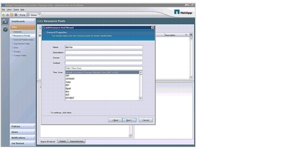
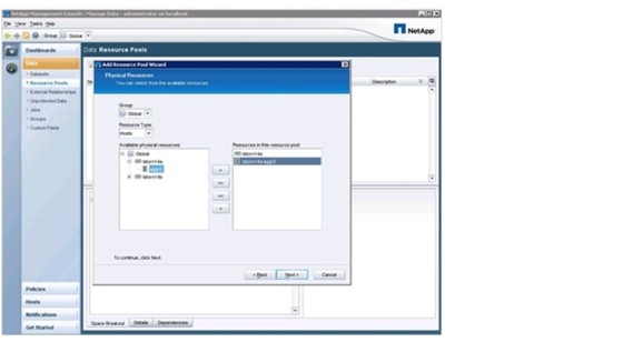
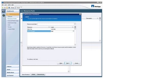
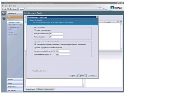
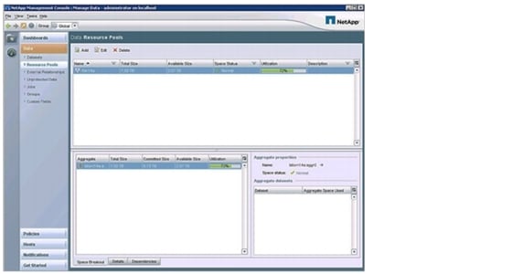
Defining Resource Pools
Provisioning Manager offers the ability to easily provision new tenants and volumes by using resource pools. A resource pool can consist of several physical controllers and aggregates. However, each resource pool should contain only one controller.
The following are the steps to define a resource pool.
1.

2.

3.
4.
5.
6.
7.
8.
NetApp recommends that you create a separate resource pool for each storage system. Repeat steps 1 through 8 to create new resource pools for additional storage systems.
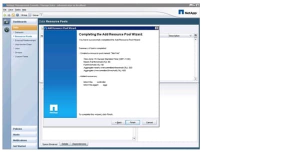
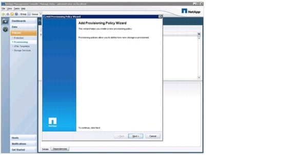
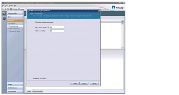
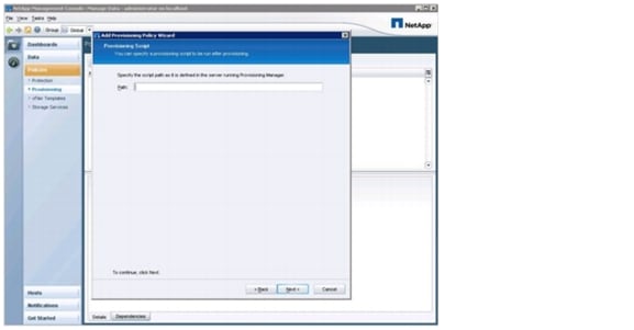
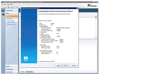
Defining Provisioning Policies
A provisioning policy defines which physical storage is to be used, based on several criteria. In combination with resource pools assigned to a dataset, the desired aggregate is used. It also allows restricting the possible storage by labels, as defined in the previous section. These labels help make the right choice of the storage in resource pools with different kinds of controllers and disks (SATA versus SAS versus FCP).
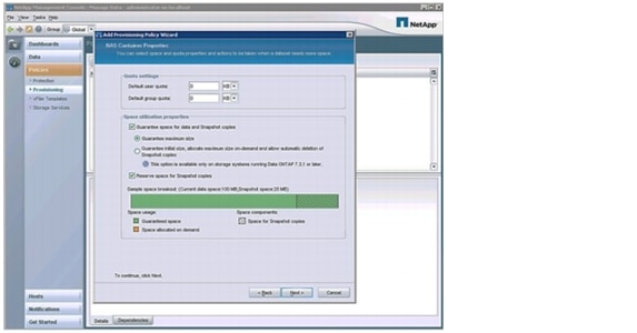
The following describes the steps define a provisioning policy for NAS.
1.

2.
3.

4.

5.

6.

7.
8.
9.
10.
11.
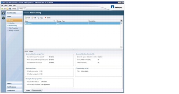
To create a new provisioning profile ("var_backup_prov_profile") for secondary storage, repeat the previous procedure, but select Secondary as the storage type in step 3.
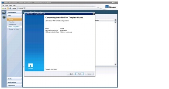
Defining vFiler Templates
A vFiler template is used to provide general information for every vFiler unit to be created by Provisioning Manager.
The following describes the steps to create a default profile
1.
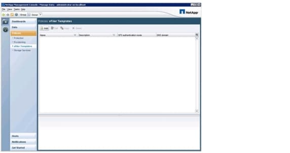
2.

3.
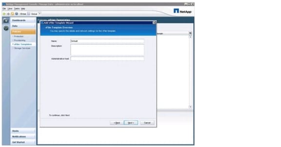
4.
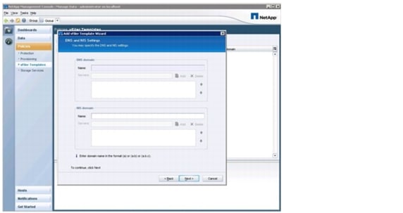
5.

6.
Setup of Infrastructure Volumes
This section describes the creation of the additional volumes, including export and backup configuration.
Note that the commands shown in the following paragraphs can be used with both storage configurations: with a single storage HA pair (minimal configuration) or with a second storage HA pair, as shown in Figure 25.
Figure 25 Overview of infrastructure tenant volumes (four controllers)
Software Share
This share contains the scripts and software that are needed for operating workflows in the different tenants later on.

Note
The following section describes the steps to create the software share.
1.
dfpm vfiler create -d "var_software_ip" -s software -a nfs,cifs,iscsi -f "var_primary_respool" software
2.
dfpm vfiler setup -t "var_vfiler_template" -r "var_vfiler_pw" -i "var_software_ip":vif0: "var_software_netmask":"var_software_vlan_id":9000:vif0 software
3.
Dfm run cmd "var_ntap_A_hostname" vol create software -s none aggr1 "var_software_size"
4.
Dfm run cmd "var_ntap_A_hostname" vfiler add software /vol/software
5.
Dfm run cmd software route add default "var_software_gw_addr" 1
6.
Dfm run cmd "var_ntap_A_hostname" wrfile -a /etc/rc vfiler run software route add default "var_software_gw_addr" 1
7.
Dfm run cmd software exportfs -p sec=sys,ro,rw="var_global_mgmt_network",anon=0 /vol/software
8.
dfpm dataset create -v "var_prim_prov_profile" -r software software
9.
dfpm dataset add software software:/software
10.
dfpm dataset modify -p "Back up" -v "var_backup_prov_profile" software Backup
11.
dfpm dataset respool add -N "Backup" software "var_secondary_respool_2nd_site"
Volume infrastructure_share
This volume is needed to store the /usr/sap/trans directory of the LVM, which holds the log files of the infrastructure components.
The following section describes the steps to create the infrastructure share.
1.
2.
dataset create -v "var_prim_prov_profile" -r infrastructure_vfiler_1 infrastructure_share
3.
dfpm dataset respool add infrastructure_share "var_primary_respool"
4.
dfpm dataset modify -p "Back up" -r infrastructure_vfiler_2 infrastructure_share Backup
5.
dfpm dataset respool add -N "Backup" infrastructure_share "var_secondary_respool_2nd_site"
6.
dfpm dataset provision -n data -s "var_infra_share_data_size" -e nfs -w all -N no -a 0 -S sys infrastructure_share
7.
dfpm dataset provision -n sap -s "var_tenant_share_sap_size" -e nfs -w all -N no -a 0 -S sys infrastructure_share
Volume infrastructure_backup
This volume is used for backup purposes; for example, archive log backup of the LVM and backup of the DFM database.
The following section describes the steps to create the infrastructure backup volume.
1.
2.
dfpm dataset create -v "var_backup_prov_profile" -r infrastructure_vfiler_2 infrastructure_backup
3.
dfpm dataset respool add infrastructure_backup "var_secondary_respool_2nd_site"
4.
dfpm dataset modify -p "Local backups only" -r infrastructure_vfiler_2 infrastructure_backup
5.
dfpm dataset provision -n data -s "var_infra_backup_size" -e nfs -w all -N no -a 0 -S sys infrastructure_backup
SMSAP Repository Volumes
These volumes are needed to store the repository database of SMSAP.
The following section describes the steps to create them.
1.
2.
dfpm dataset create -v "var_prim_prov_profile" -r infrastructure_vfiler_1 smrepo_data
3.
dfpm dataset create -v "var_prim_prov_profile" -r infrastructure_vfiler_1 smrepo_log
4.
dfpm dataset respool add smrepo_data "var_primary_respool"
5.
dfpm dataset respool add smrepo_log "var_primary_respool"
6.
dfpm dataset modify -p "Mirror" -r infrastructure_vfiler_2 smrepo_data Mirror
7.
dfpm dataset modify -p "Mirror" -r infrastructure_vfiler_2 smrepo_log Mirror
8.
dfpm dataset respool add -N "Mirror" smrepo_data "var_secondary_respool_2nd_site"
9.
dfpm dataset respool add -N "Mirror" smrepo_log "var_secondary_respool_2nd_site"
10.
dfpm dataset provision -n oracle -s 30G -e nfs -w all -N no -a 0 -S sys smrepo_data
11.
dfpm dataset provision -n oracle -s 10G -e nfs -w all -N no -a 0 -S sys smrepo_log
Back Up infrastructure_datastore
This volume contains the VMware datastore where the operating systems of all VMs and the templates for provisioning are stored. This volume is mirrored to the backup destination. A consistent Snapshot image of the datastore must be created by using the SnapManager for Virtual Infrastructure part of Virtual Storage Console 2.1. To do so, schedule a backup of the complete datastore as described in the "NetApp Virtual Storage Console 2.1 for VMware vSphere Backup and Recovery Administration Guide." Then follow the steps below to protect the backup.
1.
2.
dfpm dataset create -v "var_prim_prov_profile" -r infrastructure_vfiler_1 infrastructure_datastore
3.
dfpm dataset add infrastructure_datastore infrastructure_vfiler_1:/infrastructure_datastore_1
4.
dfpm dataset modify -p "Mirror" -v "var_backup_prov_profile" -r infrastructure_vfiler_2 infrastructure_datastore Mirror
5.
dfpm dataset respool add -N "Mirror" infrastructure_datastore "var_secondary_respool_2nd_site"
Back Up infrastructure_swap
This volume contains the VMware swap space for all VMs. Because this volume contains only temporary data, a backup is not necessary. For management and monitoring reasons, this volume should be added to a DFM dataset.
The following section describes the steps to create the dataset.
1.
2.
dfpm dataset create -v "var_prim_prov_profile" -r infrastructure_vfiler_2 infrastructure_swap
3.
dfpm dataset add infrastructure_swap infrastructure_vfiler_2:/ infrastructure_swap
Back Up vFiler Root Volumes
NetApp also recommends backing up the configuration of the vFiler units and the physical controllers (vfiler0).
The following section describes the required steps.
1.
2.
dfpm dataset create backup_prim_vfilers
3.
dfpm dataset create backup_bck_vfilers
4.
dfpm dataset add backup_prim_vfilers "var_ntap_A_hostname":/vol0
5.
dfpm dataset add backup_prim_vfilers infrastructure_vfiler_1:/infrastructure_root
6.
dfpm dataset add backup_prim_vfilers software:/software_root
7.
dfpm dataset modify -p "Back up" -v "var_backup_prov_profile" backup_prim_vfilers Backup
8.
dfpm dataset respool add -N "Backup" backup_prim_vfilers "var_secondary_respool_2nd_site"
9.
dfpm dataset add backup_bck_vfilers "var_ntap_B_hostname": /vol0
10.
dfpm dataset add backup_bck_vfilers infrastructure_vfiler_2:/infrastructure_root
11.
dfpm dataset modify -p "Back up" -v "var_prim_prov_profile" backup_bck_vfilers Backup
12.
dfpm dataset respool add -N "Backup" backup_bck_vfilers "var_primary_respool" ("var_secondary_respool_2nd_site", if second site available)
Back Up SAN Boot Volumes of ESXI Servers
NetApp also recommends mirroring the boot disks of the ESXi servers.
1.
2.
3.
dfpm dataset create esxi_boot_a
4.
dfpm dataset create esxi_boot_b
5.
dfpm dataset add esxi_boot_a "var_ntap_A_hostname":/esxi_boot_A
6.
dfpm dataset add esxi_boot_b "var_ntap_B_hostname":/esxi_boot_B
7.
dfpm dataset modify -p "Mirror" -v "var_backup_prov_profile" - esxi_boot_a Mirror
8.
dfpm dataset modify -p "Mirror" -v "var_backup_prov_profile" - esxi_boot_b Mirror
9.
dfpm dataset respool add -N "Mirror" esxi_boot_a "var_secondary_respool_2nd_site"
10.
dfpm dataset respool add -N "Mirror" esxi_boot_b "var_primary_respool" ("var_secondary_respool_2nd_site", if second site available)
11.
SAP Landscape Virtualization Manager Setup
The SAP Landscape Virtualization Manager (LVM) offers the possibility of monitoring and operating SAP system landscapes. An adaptive computing-enabled SAP landscape contains the LVM itself and host agents that monitor and interact with hardware resources and SAP systems. This section describes the installation of the ACC. The installation of the host agents is described as part of the OS template installation. The installation of LVM is done on a dedicated host in the infrastructure tenant and consists of the following steps:
•
•
•
SMSAP Repository Database
The SMSAP repository database must be installed on a Linux VM in the infrastructure tenant. This VM must be created with 4GB RAM, 20GB disk space, and two network interfaces: one interface connected to the management VLAN and one interface connected to the back-end VLAN.
Mount the volumes created for the repository database (as described in section, "SMSAP Repository Volumes") and install the SMSAP repository database. The SMSAP repository database parameters that are used during the installation must be included in the general section of each tenant configuration file /mnt/data/conf/tnnn.conf.
# generalsmsapRepositoryHostname=t001-smrepo.mgmt.t001.company.corpsmsapRepositoryPort=1521smsapRepositoryService=REPBack Up SMSAP Repository Database
The repository is backed up with the export functionality provided by Oracle. An example script is available, which can be scheduled by cron.
The following section describes the required steps.
1.
2.
chown 777 /mnt/backup/backup_repo
3.
4.
chown 777 /mnt/backup/log
5.
Restore the SMSAP Repository Database
A dedicated repository schema can be restored with imp. NetApp recommends deleting and restoring the repository user before the restore.
The following example is for the repository of tenant t009:
Import of only one Schema for a dedicated user:oracle@t001-smrepo:~> sqlplus / as sysdbaSQL*Plus: Release 10.2.0.1.0 - Production on Tue Apr 12 16:26:26 2011Copyright (c) 1982, 2005, Oracle. All rights reserved.Connected to:Oracle Database 10g Enterprise Edition Release 10.2.0.1.0 - 64bit ProductionWith the Partitioning, OLAP and Data Mining optionsSQL> drop user smrepo_t009 cascade;User dropped.SQL>SQL> create user smrepo_t009 identified by <password> default tablespace repdata_t009;User created.SQL> grant resource, connect to smrepo_t009;Grant succeeded.SQL>exitoracle@t001-smrepo:~> NLS_LANG=AMERICAN_AMERICA.WE8ISO8859P1 ;export NLS_LANGoracle@t001-smrepo:~>imp system/ucs4sap! fromuser=smrepo_t009 file=/mnt/backup/backup repo/backup "time stamp" REP.expdat log=/mnt/backup_imp.logImport: Release 10.2.0.1.0 - Production on Tue Apr 12 16:34:01 2011Copyright (c) 1982, 2005, Oracle. All rights reserved.Connected to: Oracle Database 10g Enterprise Edition Release 10.2.0.1.0 - 64bit ProductionWith the Partitioning, OLAP and Data Mining optionsExport file created by EXPORT:V10.02.01 via conventional pathimport done in WE8ISO8859P1 character set and AL16UTF16 NCHAR character setimport server uses WE8ISO8859P1 character set (possible charset conversion). importing SMREPO_T009's objects into SMREPO_T009. . importing table "SMO_31_AUTOGENPROFILE" 0 rows imported. . importing table "SMO_31_CONNECTION" 0 rows imported. . importing table "SMO_31_CONNECTMAPPINGS" 0 rows imported. . importing table "SMO_31_CONTAINER" 0 rows imported. . importing table "SMO_31_CREDENTIAL" 2 rows imported. . importing table "SMO_31_DATASET" 0 rows imported. . importing table "SMO_31_EXTERNALTABLE" 0 rows imported. . importing table "SMO_31_LOGMESSAGE" 20 rows imported. . importing table "SMO_31_NOTIFICATIONSETTINGS" 0 rows imported. . importing table "SMO_31_OPERATIONCYCLE" 1 rows imported. . importing table "SMO_31_PARAMETER" 0 rows imported. . importing table "SMO_31_PROFILE" 1 rows imported. . importing table "SMO_31_PROFILENOTIFICATION" 0 rows imported. . importing table "SMO_31_PROFILEVERSION" 1 rows imported. . importing table "SMO_31_REPOSITORYPROPERTY" 1 rows imported. . importing table "SMO_31_RETENTIONPOLICY" 4 rows imported. . importing table "SMO_31_SCHEDULEDBACKUPSET" 0 rows imported. . importing table "SMO_31_SCHEDULEDOPERATION" 0 rows imported. . importing table "SMO_31_SNAPPOINTGROUP" 0 rows imported. . importing table "SMO_31_SUMMARYNOTIFICATION" 0 rows imported. . importing table "SMO_31_SUMMARYPROFILES" 0 rows importedAbout to enable constraints...Import terminated successfully without warnings.oracle@t001-smrepo:~>SMSAP Installation on the DFM Server
For several workflows, the DFM host must run SMSAP commands, so SMSAP must be installed on the host. There is no need to install SnapDrive for UNIX, and the SMSAP server does not need to be started at the host.
After SMSAP is installed, the following configuration must be done in the SMSAP configuration file:
t001-dfm:/mnt/software/scripts # vi /opt/NetApp/smsap/properties/smsap.config******# If set to true the users OS password will be cached in the credential file in an encrypted form.host.credentials.persist=true*******Infrastructure Tenant-Specific Services
The infrastructure tenant-specific services must be installed on a Linux VM in the infrastructure tenant. This VM must be created with two network interfaces, one interface connected to the management VLAN and one interface connected to the back-end VLAN.
In the infrastructure tenant, the only service that is provided is DNS. DNS service is provided by using dnsmasq, a lightweight DNS and DHCP server included as an optional installation package with each major distribution. It must be installed during the OS installation process.
Depending on the version of dnsmasq shipped with the OS, an update is required. You can update the shipped version with the latest version of dnsmasq. The version used in this document is dnsmasq-2.55. Instead of the version shipped with your OS, you can download the sources and build dnsmask from the sources.
This section describes the DNS configuration.
Configuring DNS
Figure 26 shows the DNS structure of the infrastructure tenant and the other tenants.
Figure 26 DNS structure of tenants

The configuration is done through the files /etc/dnsmasq.conf, /etc/hosts, and /etc/resolv.conf. The DNS in the infrastructure tenant:
•
•
•
The example assumes that the DNS domain for the infrastructure tenant is t001.company.corp.
Configuring /etc/Dnsmasq.conf
The configuration is done through the following entries in the dnsmasq.conf file:
## Definition of the infrastructure tenant domaindomain-needed#domain=t001.company.corpdomain=t001.company.corp,192.168.99.0/24domain=bknd.t001.company.corp,192.168.101.0/24#local=/t001.company.corp/local=/99.168.192.in-addr.arpa/### Corporate DNS serverserver=corporateDNSip### Section for each available tenant## add new sections for newly provisioned tenants# route forward queries for *.t002.company.corp to 192.168.2.50 (T002 DNS)Server=/t002.company.corp/192.168.2.50# route reverse lookups to 192.168.2.50 (T002 DNS)Server=/2.168.192.in-addr.arpa/192.168.2.50Server=/102.168.192.in-addr.arpa/192.168.2.50...##no-dhcp-interface=eth0no-dhcp-interface=eth1No DHCP is required in the infrastructure tenant, so it is disabled through the following lines:
no-dhcp-interface=eth0no-dhcp-interface=eth1Configuring /etc/hosts
Dnsmasq reads the local /etc/hosts file to gather the name and IP mappings required to act as a DNS server. The local /etc/hosts of a typical FlexPod infrastructure tenant may hold information about the following services and hosts:
127.0.0.1 localhost##### Physical Management LAN #########192.168.98.10 lstorn14a.company.corp lstorn14a192.168.98.11 lstorn14b.company.corp lstorn14b##### Software LAN ######192.168.96.10 software.company.corp software#####T001#########192.168.99.50 t001-0-lnx.t001.company.corp t001-0-lnx192.168.101.50 t001-0-lnx.bknd.t001.company.corp192.168.99.30 t001-smrepo.t001.company.corp t001-smrepo smrepo192.168.101.30 t001-smrepo.bknd.t001.company.corp192.168.99.68 smt-dfm.t001.company.corp smt-dfm192.168.101.68 smt-dfm.bknd.t001.company.corp192.168.99.78 vcenter.t001.company.corp vcenter192.168.101.78 vcenter.bknd.t001.company.corp192.168.99.101 t001-acc.t001.company.corp t001-acc acc192.168.101.101 t001-acc.bknd.t001.company.corp# vfiler192.168.101.10 t001-1-prim.bknd.t001.company.corp infrastructure_vfiler_1192.168.101.11 t001-1-sec.bknd.t001.company.corp infrastructure_vfiler_2192.168.101.13 t001-2-prim.bknd.t001.company.corp infrastructure_vfiler_3192.168.101.13 t001-2-sec.bknd.t001.company.corp infrastructure_vfiler_4# ESX server192.168.99.210 esxserver1.t001.company.corp esxserver1192.168.99.211 esxserver2.t001.company.corp esxserver2192.168.99.212 esxserver3.t001.company.corp esxserver3192.168.99.213 esxserver4.t001.company.corp esxserver4Configuring /etc/resolv.conf
The resolv.conf file defines the domain and search list and should point to the dnsmasq server (127.0.0.1) as nameserver.
domain t001.company.corpsearch t001.company.corpsearch company.corpnameserver 127.0.0.1Service Activation
To enable the configuration, the dnsmasq service must be restarted with the following command:
service dnsmasq restartLogging information for dnsmasq can be found in /var/log/dnsmasq.log.
Additional Steps for Handling a Second FlexPod Infrastructure
Creation of Additional VMware Datastores at Additional Storage Systems
If additional storage systems and ESXi servers are available in an additional data center, NetApp recommends using an additional VM datastore for this second location.
This section describes how to set up additional vFiler units and volumes for this datastore.
1.
dfpm vfiler template get infrastructure
2.
dfpm vfiler template create infrastructure
3.
dfpm vfiler template set infrastructure dnsServers="var_global_nfs_dns_ip"
4.
dfpm vfiler template set infrastructure dnsDomain="var_global_nfs_dns_domain"
5.
dfpm vfiler create -d <IP of 3rd infrastructure vfiler> -s infrastructure -a nfs,cifs,iscsi -f <resource pool of desired physical controller > infrastructure_vfiler_3
6.
dfpm vfiler create -d <IP of 4th infrastructure vfiler> -s infrastructure -a nfs,cifs,iscsi -f <resource pool of desired physical controller > infrastructure_vfiler_4
7.
dfpm vfiler setup -t infrastructure -r "var_vfiler_pw" -i <IP of 3rd infrastructure vfiler>:<virtualInterface>:"var_global_nfs_net_mask": "var_global_nfs_vlan_id":9000:<<virtualInterface>> infrastructure_vfiler_3
8.
9.
dfm run cmd infrastructure_vfiler_3 options http.admin.enable on
10.
dfpm vfiler setup -t infrastructure -r "var_vfiler_pw" -i <IP of 4th infrastructure vfiler>:<virtualInterface>:"var_global_nfs_net_mask": "var_global_nfs_vlan_id":9000:<<virtualInterface>> infrastructure_vfiler_4
11.
12.
dfm run cmd infrastructure_vfiler_4 options http.admin.enable on
13.
dfpm dataset add backup_prim_vfilers infrastructure_vfiler_3/<name of root volume>
14.
dfpm dataset add backup_bck_vfilers infrastructure_vfiler_4/<name of root volume>
A network interface may already exist on a controller or its partner if a vFiler unit of the same tenant exists on this controller or its partner.
If an interface already exists, the setup commands for the vFiler units in step 7 and step 9 must be replaced with the following:
For step 7:
dfpm vfiler setup -t infrastructure -r "var_vfiler_pw" -i <IP of 3rd infrastructure vfiler>:<<virtualInterface>>-"var_global_nfs_vlan_id":"var_global_nfs_net_mask" infrastructure_vfiler_3
For step 9:
dfpm vfiler setup -t infrastructure -r "var_vfiler_pw" -i <IP of 4th infrastructure vfiler>:<<virtualInterface>>-"var_global_nfs_vlan_id":"var_global_nfs_net_mask" infrastructure_vfiler_4
The following section describes the steps to create the volumes for the new datastore.
Create and configure the datastore for the VMs:
1.
2.
3.
4.
5.
Create and configure the datastore for SWAP:
1.
2.
3.
4.
5.
6.
7.
Next, create the datasets and backup for the new datastores.
The volume infrastructure_datastore_2 contains the VMware datastore where the operating systems of all VMs and the templates for provisioning are stored. This volume is mirrored to the backup destination. A consistent Snapshot image of the datastore must be created by using the SnapManager for Virtual Infrastructure part of Virtual Storage Console 2.1. To do so, schedule a backup of the complete datastore as described in the "NetApp Virtual Storage Console 2.1 for VMware vSphere Backup and Recovery Administration Guide." Do the following steps to protect the backup.
1.
2.
dfpm dataset create -v "var_prim_prov_profile" -r infrastructure_vfiler_3 infrastructure_datastore_2.
3.
dfpm dataset add infrastructure_datastore_2 infrastructure_vfiler_3:/infrastructure_datastore_2.
4.
dfpm dataset modify -p "Mirror" -v "var_backup_prov_profile" -r infrastructure_vfiler_2 infrastructure_datastore_2 Mirror.
5.
dfpm dataset respool add -N "Mirror" infrastructure_datastore_2 "var_secondary_respool".
The volume infrastructure_swap_2 contains the VMware swap space for all VMs. Because this volume contains only temporary data, a backup is not necessary. For management and monitoring reasons, this volume should be added to a DFM dataset.
The following section describes the steps to create the dataset.
1.
2.
dfpm dataset create -v "var_prim_prov_profile" -r infrastructure_vfiler_4 infrastructure_swap_2
3.
dfpm dataset add infrastructure_swap_infrastructure_vfiler_4:/ infrastructure_swap_2
Connect these new datastores to all ESXi hosts.
Copy all needed templates to the new datastore. Rename the templates at the new datastore before you import them.
Installation and Configuration of Operating System Images
SAP Applications built on FlexPod supports different Linux distributions. In this deployment guide, the following Linux versions are covered and tested:
SuSE Linux Enterprise Server (SLES 10/11) (See SAP note 1310037 for supported OS versions.)
Red Hat Enterprise Server 5.5 (See SAP note 1048303 for supported OS versions.)
There are different options to install Linux in the environment as a virtual machine or on physical blades. Throughout this deployment guide, the combinations tested are:
•
•
•
This section focuses on the creation of a virtual machine template only. Refer to:
•
•
The following subsections focus on the FlexPod specific tasks for the VMware OS installation. The actual OS installations for SuSE and Red Hat can be found in Appendix A and Appendix B and are referenced accordingly. The remainder of this section describes:
•
•
•
•
LINUX Template Creation
Virtual Hardware Provisioning
This subsection describes the creation of a VMware template, which is used for OS and VM provisioning. The following section describes the required steps.
1.

2.

3.
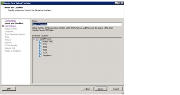
4.
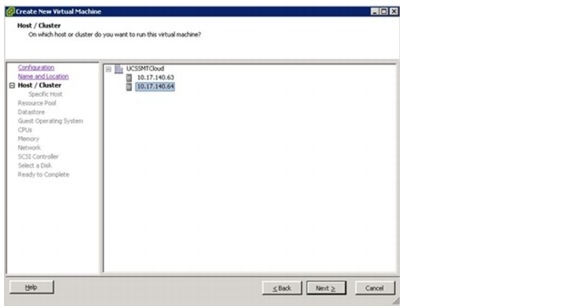
5.

6.
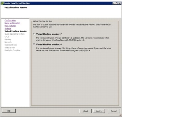
7.

8.
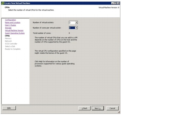
9.

10.

11.
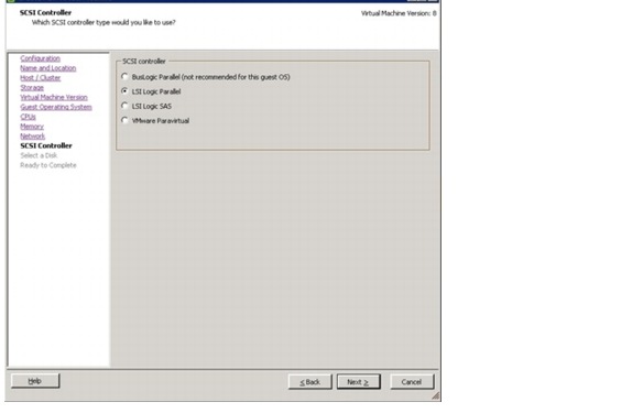
12.

13.
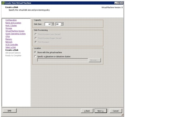
14.
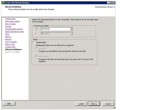
15.

16.

17.

18.
Linux Installation
Linux Installation
When you boot the virtual machine with the installation CD mounted, the Linux-specific installation process starts. Refer to:
•
•
These appendixes also include the distribution-specific configuration for networking, DHCP, and NIS, and special kernel settings required by SAP. Once this has been done, install the VMware tools into this VM.
Installation of Additional Software Components
Additional software must be installed after the basic installation and configuration steps. Some of these software components must have a certain user or group assignment that is usually provisioned through the tenant-specific services VM and must therefore be mapped to the user and group IDs that are configured in your tenant-specific services template.
Two options are available:
•
•
The rest of this section describes the latter option.
Preparation
At this point the OS does not have access to the central software share, where software and scripts should be provisioned. The following section describes the steps to create the mountpoints and mount the software share manually.
1.
2.
# mkdir /mnt/software /mnt/data /mnt/backup
3.
# chmod 777 /mnt/software
4.
# mount -t nfs 192.168.96.10:/vol/software /mnt/software
This enables you to set all required software components and the scripts provided with SAP Applications built on FlexPod to read-only.
Installation of SAP Host Agents
The SAPHOSTAGENT package contains all of the required elements for centrally monitoring any host. Download SAPHOSTAGENT.SAR from SAP Service Marketplace and install the package. .
To install the package directly, do the following steps.
1.
2.
# groupadd -g 1001 sapsys
3.
# useradd sapadm -u 1000 -g 1001 -c "SAP System Administrator"
4.
# passwd sapadm
5.
6.
7.
8.
9.
Oracle Client Installation
The Oracle client is part of the operating system image. To install the client, a valid version to run the SAP systems (Oracle Client for Linux x86 64bit 10.2.0.4, for example) must be downloaded from the SAP Service Marketplace. The manual installation of the Oracle client is described in detail in SAP note 819829; the main steps are as follows:
1.
2.
3.
As an alternative to the manual installation, the client can be added to the operating system image after the first SAP system is installed. This process is described in section, "Oracle Client - Template Update."
Be sure to change the file ownership of all files and directories of the client to a different user than the ora<sid> user. The group must be dba so that all systems can access the client. During a standard installation, the owner of all directories and files in /oracle/client/ is set to ora<sid> with groupid dba.
SnapDrive Installation and Configuration
Install SnapDrive for UNIX as described in the "SnapDrive for UNIX Administration Guide" that is applicable to your operating system. After installation, the following configuration file changes must be made:
•
•
•
t002-1-lnx:/opt/NetApp/snapdrive # vi snapdrive.confuse-https-to-filer=off # Communication with filer done via HTTPS instead of HTTPsnapcreate-check-nonpersistent-nfs=off # Check that entries exist in /etc/fstab for specified nfs fs.autosupport-enabled=offSMSAP Installation and Configuration
Install SnapManager for SAP as described in the "SnapManager for SAP Installation and Administration Guide" applicable to your operating system and release of SnapManager. During the installation, user and group must be configured to root/root:
Please enter the operating system user name and group name that should
be used
to run SnapManager for SAP commands. Press <ENTER> to accept the defaultvalues.User Name (DEFAULT: oracle): rootUser Group (DEFAULT: dba): rootInsert the following option into /opt/NetApp/smsap/properties/smsap.config:
auto_support.on=offjava.security File
In the java.security file, change /dev/urandom to /dev/./urandom:
cat /opt/NetApp/smsap/jre/lib/security/java.security | grep securerandom# the securerandom.source property. If an exception occurs whensecurerandom.source=file:/dev/./urandom# Specifying this system property will override the securerandom.sourceAuthorization Configuration
Create /etc/pam.d/snapmanager for SMSAP:
t002-1-lnx:/etc/pam.d # vi snapmanagerInsert : auth required pam_unix.soaccount required pam_unix.sot002-1-lnx:/etc/pam.d # cat snapmanagerauth required pam_unix.soaccount required pam_unix.sot002-1-lnx:/etc/pam.d #SMSAP Post-Cloning Plug-In Configuration
The scripts os_db_authentication.sh and sap_follow_up_activities.sh must be copied from /opt/NetApp/smsap/plugins/examples/clone/create/post to /opt/NetApp/smsap/plugins/clone/create/post/.
The script cleanup.sh must be copied from /opt/NetApp/smsap/plugins/examples/clone/create/pre to /opt/NetApp/smsap/plugins/clone/create/post/.
The function execute in the script os_db_authentication.sh must be adapted.
This is the original version:
function execute {EXIT=0[ -z "$SCHEMAOWNER" ] && EXIT=4 && echo "parameter [SCHEMAOWNER] not set"[ -z "$ORADBUSR_FILE" ] && EXIT=4 && echo "parameter [ORADBUSR_FILE] not set"[ -z "$SM_TARGET_SID" ] && EXIT=4 && echo "parameter [SM_TARGET_SID] not set"[ -z "$SM_ORIGINAL_SID" ] && EXIT=4 && echo "parameter [SM_ORIGINAL_SID] not set"[ $EXIT -ne 0 ] && echo "processing stopped due to missing parameters" && _exit $EXIT[ ! -f "$ORADBUSR_FILE" ] && echo "file [$ORADBUSR_FILE] is not a regular file" && _exit 4sqlplus /nolog @${ORADBUSR_FILE} $SCHEMAOWNER UNIX $SM_TARGET_SID xsqlplus /nolog <<EOFset echo onset termout onconnect / as sysdbainsert into OPS\$${SM_TARGET_SID}ADM.SAPUSER select * from OPS\$${SM_ORIGINAL_SID}ADM.SAPUSER;commit;exitEOFThis is the corrected version:
function execute {EXIT=0[ -z "$SCHEMAOWNER" ] && EXIT=4 && echo "parameter [SCHEMAOWNER] not set"[ -z "$ORADBUSR_FILE" ] && EXIT=4 && echo "parameter [ORADBUSR_FILE] not set"[ -z "$SM_TARGET_SID" ] && EXIT=4 && echo "parameter [SM_TARGET_SID] not set"[ -z "$SM_ORIGINAL_SID" ] && EXIT=4 && echo "parameter [SM_ORIGINAL_SID] not set"[ $EXIT -ne 0 ] && echo "processing stopped due to missing parameters" && _exit $EXIT[ ! -f "$ORADBUSR_FILE" ] && echo "file [$ORADBUSR_FILE] is not a regular file" && _exit 4sqlplus /nolog @${ORADBUSR_FILE} $SCHEMAOWNER UNIX $SM_TARGET_SID x. ${ORACLE_HOME}/../.profile && . ${ORACLE_HOME}/../.dbenv.sh${DIR_LIBRARY}/brconnect -u / -c force -f chpass -o SAPSR3 -p sap_exit $?}The function execute in the script cleanup.sh must be adapted.
This is the original version:
function execute {echo "cleaning up the environment"[ -z "$SM_TARGET_SID" ] && echo "target SID [SM_TARGET_SID] not set" && _exit 4files_to_cleanup=("/oracle/${SM_TARGET_SID}/origlogA/cntrl/cntrl${SM_TAR GET_SID}.dbf:N""/oracle/${SM_TARGET_SID}/mirrlogB/cntrl/cntrl${SM_TARGET_SID}.dbf:N""/oracle/${SM_TARGET_SID}/sapdata1/cntrl/cntrl${SM_TARGET_SID}.dbf:N""/oracle/${SM_TARGET_SID}/origlogA/log_g11m1.dbf:N""/oracle/${SM_TARGET_SID}/origlogB/log_g12m1.dbf:N""/oracle/${SM_TARGET_SID}/origlogA/log_g13m1.dbf:N""/oracle/${SM_TARGET_SID}/origlogB/log_g14m1.dbf:N""/oracle/${SM_TARGET_SID}/mirrlogA/log_g11m2.dbf:N""/oracle/${SM_TARGET_SID}/mirrlogB/log_g12m2.dbf:N""/oracle/${SM_TARGET_SID}/mirrlogA/log_g13m2.dbf:N""/oracle/${SM_TARGET_SID}/mirrlogB/log_g14m2.dbf:N""/oracle/${SM_TARGET_SID}/saptrace/usertrace:Y""/oracle/${SM_TARGET_SID}/saptrace/background:Y""/oracle/${SM_TARGET_SID}/102_64/dbs/init${SM_TARGET_SID}.ora:Y")IFS=^for entry in ${files_to_cleanup[@]} ; dofile=$(echo "$entry" | awk -F':' '{ print $1 }')save=$(echo "${entry}" | awk -F':' '{ print $2 }')[ -f "$file" ] || echo "[info] file [$file] not found" && continuepreserve $file $saveif [ $? -ne 0 ] ; thenecho "cannot preserve [$file]"_exit 4fidone_exit 0}This is the corrected version:
function execute {echo "cleaning up the environment"[ -z "$SM_TARGET_SID" ] && echo "target SID [SM_TARGET_SID] not set" && _exit 4files_to_cleanup=("/oracle/${SM_TARGET_SID}/origlogA/cntrl/cntrl${SM_TAR GET_SID}.dbf:N""/oracle/${SM_TARGET_SID}/origlogB/cntrl/cntrl${SM_TARGET_SID}.dbf:N""/oracle/${SM_TARGET_SID}/102_64/dbs/cntrl${SM_TARGET_SID}.dbf:N""/oracle/${SM_TARGET_SID}/origlogA/log_g11m1.dbf:N""/oracle/${SM_TARGET_SID}/origlogB/log_g12m1.dbf:N""/oracle/${SM_TARGET_SID}/origlogA/log_g13m1.dbf:N""/oracle/${SM_TARGET_SID}/origlogB/log_g14m1.dbf:N""/oracle/${SM_TARGET_SID}/mirrlogA/log_g11m2.dbf:N""/oracle/${SM_TARGET_SID}/mirrlogB/log_g12m2.dbf:N""/oracle/${SM_TARGET_SID}/mirrlogA/log_g13m2.dbf:N""/oracle/${SM_TARGET_SID}/mirrlogB/log_g14m2.dbf:N""/oracle/${SM_TARGET_SID}/saptrace/usertrace:Y""/oracle/${SM_TARGET_SID}/saptrace/background:Y""/oracle/${SM_TARGET_SID}/102_64/dbs/init${SM_TARGET_SID}.ora:Y")IFS=^for entry in ${files_to_cleanup[@]} ; dofile=$(echo "$entry" | awk -F':' '{ print $1 }')save=$(echo "${entry}" | awk -F':' '{ print $2 }')# [ -f "$file" ] || echo "[info] file [$file] not found" && continue# preserve $file $saverm -rf $fileif [ $? -ne 0 ] ; thenecho "cannot preserve [$file]"_exit 4fidone_exit 0}Download oradbusr10.zip as described in SAP note 50088. Extract the zip file and copy ORADBUSR.SQL to /opt/NetApp/smsap/plugins/clone/create/post/.
System Boot Configuration
The script flexpod_config is used to execute the following tasks during system boot:
•
•
•
•
•
The mount points /mnt/software, /mnt/data and /mnt/backup must be created. The permissions of these mountpoints must be changed to 777.
The script flexpod_config must be copied to /etc/rc.d.
The system boot configuration is done with the chkconfig command:
t003-20-lnx:/etc/rc.d # chkconfig --add flexpod_configflexpod_config 0:off 1:off 2:off 3:on 4:off 5:on 6:offConverting the Virtual Machine to a Template
After any changes to the template, the following checks must be done before converting the VM to the template.
SnapDrive
When the template is booted, SnapDrive starts with a cron job that waits for 300 seconds. Before converting the VM to the template, SnapDrive must have finished the starting process.
Cron job is still running; SnapDrive is not running yet:
t003-17-lnx:~ # ps -ef | grep snaproot 6609 6608 0 10:01 ? 00:00:00 /bin/sh /opt/NetApp/snapdrive/snapdrived_cront003-17-lnx:~ # snapdrived status9001-016 SOAP ERROR : 24 : A connection error occured. Please check if snapdrived is runningCron job is finished; SnapDrive is running:
t003-17-lnx:~ # ps -ef | grep snaproot 6690 1 0 10:06 ? 00:00:00 /opt/NetApp/snapdrive/bin/snapdrived startt003-17-lnx:~ # snapdrived statusSnapdrive Daemon Version : 4.2 (Change 1189505 Built Sat Oct 2 10:27:12 PDT 2010)Snapdrive Daemon start time : Mon Feb 21 10:06:01 2011Total Commands Executed : 1Job Status:No command in executionAfter SnapDrive is started, any appliance configuration must be deleted (this configuration has been configured during boot of the OS template). In the following example, the entries t002-1-prim and t002-1-bck and the dfm entry must be deleted with the snapdrive config delete command.
t002-39-lnx:/ # snapdrive config listusername appliance name appliance type----------------------------------------------------------------sdu-admin t002-1-prim StorageSystemsdu-admin t002-1-bck StorageSystemsdu-admin-t002 smt-dfm.mgmt.t001.company.corp DFMThe snapdrive config list command must not contain any entry.
t002-39-lnx:/ # snapdrive config listusername appliance name appliance type-----------------------------------------------------------UDEV Configuration (SuSE Only)
Disable the use of persistent network device names by clearing the UDEV configuration for network interfaces according to the Novell/SUSE TID 3048119:
cat< /dev/null > /etc/udev/rules.d/70-persistent-net.rulesEmpty /etc/HOSTNAME
In order to get a valid hostname during the first boot, it is necessary (for SLES 11 based templates) to delete the hostname as part of the template creation:
t002-39-lnx:/ # echo "" > /etc/HOSTNAMEAfter all steps described in the previous sections have been completed, shut down the VM by executing halt in a terminal window. When the VM is turned off, right-click the VM in the vSphere client and select Template > Convert to Template. The template is now usable for deploying new VMs
Linux Template Maintenance
Some of the software components may require maintenance, or they may change over time. This is especially true for the preinstalled Oracle client software. During an SAP system installation, a new version (or patch) of the Oracle client software may be installed. Therefore you must consider a strategy for maintaining the OS template.
This section does not specify any explicit software change, but instead gives a general procedure that must be followed according to your requirements.
The steps to update a template are:
1.
2.
3.
4.
Create a New Master
Note
The important decision you must make is in which tenant you should deploy this machine. For example, if you want to patch the Oracle client software, it is important to work in a tenant, where all the required Oracle user settings are applied to the tenant-specific services VM.
NetApp recommends doing maintenance tasks in a dedicated maintenance tenant to simulate a real production environment in terms of users, networks, and other specifics.
Start the Virtual Machine and Adapt the Software
After you start the VM, make sure that it is running and that all users and shared services are available. Make your software modifications and test the VM.
In the case of an Oracle client change, you can also copy the updated client that results from an SAP installation or patch in one of the systems, if changes have been made using the same template. (See section, "SAP System Postinstallation Tasks.")
Clean the Virtual Machine and Shut Down
Follow the steps from section, "LINUX Template Creation." You should think of a naming convention for your templates so that you can track which changes have been made. It is obvious that at this point only a new template is available, and that running systems are still using the previous version.
Test and Release the New Template
Be sure to test the functionality and interoperability of the template with your existing running system. The workflows provided by SAP Applications built on FlexPod-the Repairsystem Workflow-give you an almost automated procedure for cloning an existing system into a new test tenant. However, this time you should use the new OS template. This enables you to perform tests without any influence on the running system.
If you intend to exchange the OS of an existing landscape, you must deploy the servers based on the new OS template and then relocate the running system onto those new servers. This requires downtime and a maintenance window.
Tenant-Specific Services Virtual Machine Template
Tenant-specific services are currently provided by a lightweight Linux VM in each tenant.
The tenant-specific services VM template is built based on the Linux VMware image described in section, "Linux Template Creation." For the tenant-specific services system, this section focuses on a SuSE Linux distribution.
Some additional packages are installed and configured to form the tenant-specific services VM template. The following packages must be installed on the VM. All of them can be installed through the SLES installer, YaST.
•
•
•
Dnsmasq
Dnsmasq is a lightweight DNS and DHCP server that is included as an optional installation package with each major distribution. It must be installed during the OS installation process.
Depending on the version of dnsmasq shipped with the OS, an update is required. You can update the shipped version with the latest version of dnsmasq. The version used in this document is dnsmasq-2.55. Instead of using the version shipped with your OS, you can also download the source files and build dnsmasq.
The following section describes the steps to install dnsmasq.
1.
2.
3.
4.
groupadd -g 1000 sapinst
groupadd -g 1001 sapsys
groupadd -g 1002 dba
groupadd -g 1003 oper
5.
# useradd sapadm -u 1000 -g 1001 -c "SAP System Administrator"
6.
# passwd sapadm
Ypserv
The following section describes the steps to install ypserv.
1.
2.
MINUID=1000
MINGID=1000
all: passwd group services
3.
yppasswdd
Make sure that the yppasswdd service is available (installed through the ypserv package) and configured in the correct runlevel (chkconfig yppasswdd).
Converting the Virtual Machine to a VMware Template
After all changes have been made to the tenant-specific services template, some cleanup steps must be completed before converting the VM to the VMware template.
Disable the use of persistent network device names by clearing the UDEV configuration for network interfaces according to the Novell/SUSE TID 3048119:
cat< /dev/null > /etc/udev/rules.d/70-persistent-net.rulesAfter all steps described in the previous sections have been completed, shut down the VM by executing halt in a terminal window. When the VM is turned off, right-click it in the vSphere client and select Template > Convert to Template. The template is now usable for deploying new VMs.
Tenant Provisioning
A managed tenant consists of the following components:
•
–
•
–
•
–
–
–
–
•
•
Figure 27 shows the computing, network, and storage components of each tenant.
Figure 27 Overview of tenant components
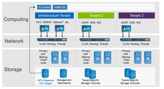
NetApp recommends creating a specific test and maintenance tenant to perform maintenance tasks such as OS maintenance in a production-like environment.
The setup of the tenant must be done in the sequence described in the following sections.
Tenant Configuration File
All of the necessary parameters describing the tenant must be provided in the tenant configuration file tnnn.conf. The tenant configuration file must be stored at /mnt/data/conf in the infrastructure tenant. Most scripts that are used during the tenant provisioning process read the configuration from that file. A copy of this file must also be available in each tenant as part of the tenant provisioning process. It must be stored in /mnt/data/conf and be available on every server in the tenant.
The parameters in the configuration file are described in section, "Descriptions of Configuration Files."
Network
A managed tenant is a separate unit with its own vFiler systems, a dedicated tenant access VLAN, and a dedicated tenant back-end VLAN.
•
•
This section describes the use of Cisco Nexus 1000v as a distributed switch and Cisco Catalyst as the central router. If you intend to use VM-FEX instead of Cisco Nexus 1000v for adding networks, refer to Appendix D, "Adding additional tenant to distributed port group to vCenter." If you are using the routing capabilities of the Cisco Nexus 55xx switches, refer to Appendix E.
The following section lists all of the commands that are required to configure the access and back-end network for a new tenant.
Step 1
Process
Log in to "var_nexus_A_hostname" and "var_nexus_B_hostname".
Conf tvlan "var_new_tenant_vlan_id_access"name "var_new_tenant_name"-accessexitinterface Vlan "var_new_tenant_vlan_id_access"no shutdownexitinterface port-channel13switchport trunk allowed vlan add "var_new_tenant_vlan_id_access"exitinterface port-channel14switchport trunk allowed vlan add "var_new_tenant_vlan_id_access"exitvlan "var_new_tenant_vlan_id_backend"name "var_new_tenant_name"-backendexitinterface port-channel11switchport trunk allowed vlan add "var_new_tenant_vlan_id_backend"exitinterface port-channel12switchport trunk allowed vlan add "var_new_tenant_vlan_id_backend"exitexitcopy run startexitVerification
Run the show run command and see whether the VLAN configuration exists.
Step 2
Process
Log in to one of the fabric interconnects of the Cisco UCS through ssh.
scope eth-uplinkcreate vlan "var_new_tenant_name"-access "var_new_tenant_vlan_id_access"exitcreate vlan "var_new_tenant_name"-backend "var_new_tenant_vlan_id_backend"exitexitcommit-bufferscope org FlexPodscope vnic-templ vNIC_Template_Aenter eth-if "var_new_tenant_name"-accessset default-net noexitenter eth-if "var_new_tenant_name"-backendset default-net noexitcommit-bufferscope vnic-templ vNIC_Template_Benter eth-if "var_new_tenant_name"-accessset default-net noexitenter eth-if "var_new_tenant_name"-backendset default-net noexitcommit-bufferexitexitStep 3
Process
Log in to the Cisco Nexus 1000V VSM.
Conf tvlan "var_new_tenant_vlan_id_access"name "var_new_tenant_name"-accessvlan "var_new_tenant_vlan_id_backend"name "var_new_tenant_name"-backendexitport-profile type vethernet "var_new_tenant_name"-accessvmware port-groupswitchport mode accessswitchport access vlan "var_new_tenant_vlan_id_access"no shutdownstate enabledport-profile type vethernet "var_new_tenant_name"-backendvmware port-groupswitchport mode accessswitchport access vlan "var_new_tenant_vlan_id_backend"no shutdownstate enabledexitexitcopy run startConfigure the inter-VLAN routing function on the Cisco Catalyst 4900 switch. Log in to the Cisco Catalyst 4900 and execute the following commands:
EnableConf terminalvlan "var_new_tenant_vlan_id_access"name "var_new_tenant_name"-accessexitip access-list standard Vlan"var_new_tenant_vlan_id_access"permit "var_new_tenant_network" 0.0.0.255permit "var_software_network" 0.0.0.255permit "var_global_mgmt_network" 0.0.0.255deny anyexitinterface Vlan"var_new_tenant_vlan_id_access"ip address "var_new_tenant_gw_addr" "var_new_tenant_netmask"ip access-group Vlan"var_new_tenant_vlan_id_access" inip access-group Vlan "var_new_tenant_vlan_id_access" outno shutdownexitinterface TenGigabitEthernet1/2switchport trunk allowed vlan add "var_new_tenant_vlan_id_access"exitinterface TenGigabitEthernet1/7switchport trunk allowed vlan add "var_new_tenant_vlan_id_access"exitcopy run startexitCreating VMware Folder
In the VMware vCenter server, create a folder with the tenant name. After connecting to the vCenter server, execute the PowerCLI command:
new-folder -name <<tenantId>> -location vmConfiguring New Storage
This section describes how to create new vFiler units and new volumes for a new tenant. It also describes how to automatically assign protection polices and relationships for the tenant-specific volumes. The setup can be done either by executing the described commands at the DFM server or by using the example scripts create_vfiler.ah and create_vfiler_wrapper.sh.
The network configuration for the tenant must be done before the storage configuration. The following information must be provided and configured in the tenant configuration file (see section 16, " Descriptions of Configuration Files").
•
–
–
•
•
–
–
–
•
•
•
•
•
•
•
•
•
•
•
–
•
–
•
•
Script-Based Storage Setup
The shell script create_vfiler_wrapper.sh loads the necessary parameters out of the tenant-specific configuration file and calls create_new_vfiler.sh, which creates the required vFiler units and provisions the required volumes.
Manual vFiler Unit Creation and Configuration
This subsection describes the commands necessary to create the required vFiler units, by using the example scripts previously described.
The following list describes the commands that are executed at the DFM server host.
1.
dfpm vfiler template get <<tenantId>>
2.
dfpm vfiler template create <<tenantId>>
3.
dfpm vfiler template set <<tenantId>> dnsServers=<<dnsBkndIp_1>>
4.
dfpm vfiler template set <<tenantId>> dnsDomain=<<dnsDomainBackend>>
5.
dfpm vfiler create -d <<primVfilerIp_1>> -s ipspace-<<tenantId>> -a nfs,cifs,iscsi -f <<primaryResourcePool_1>> <<tenantId>>-1-prim
6.
dfpm vfiler create -d "var_new_tenant_sec_vfiler_ip" -s ipspace-"var_new_tenant_name" -a nfs,cifs,iscsi -f <<secondaryResourcePool_1>> <<tenantId>>-1-bck
7.
dfpm vfiler setup -t <<tenantId>> -r <<vfiler password>> -i <<primVfilerIp_1>>:<<virtualInterface>>:<<netmaskBackend>>: <<vlanIdBackend>>:9000:<<virtualInterface>> <<tenantId>>-1-prim
Note
8.
dfm run cmd <<tenantId>>-1-prim options http.admin.enable on
9.
dfpm vfiler setup - t <<tenantId>> -r <<vfiler password>> -i <<secVfilerIp_1>>:<<virtualInterface>>:<<netmaskBackend>>: <<vlanIdBackend>>:9000:<<virtualInterface>> <<tenantId>>-1-bck
Note
10.
dfm run cmd <<tenantId>>-1-bck options http.admin.enable on
11.
dfpm dataset add backup_prim_vfilers <<tenantId>>-1-prim:/<name of root volume>
12.
dfpm dataset add backup_bck_vfilers <<tenantId>>-1-bck:/<name of root volume>
If a vFiler unit of the same tenant exists on this controller or its partner, a network interface may already exist on a controller or its partner. If an interface already exists, the setup commands for the vFiler units in step 7 and step 9 must be replaced with the following commands:
For step 7:
dfpm vfiler setup  -t <<tenantId>>  -r <<vfiler password>> -i
<<primVfilerIp_1>>:<<virtualInterface>>-<<vlanIdBackend>>:<<netmaskBackend>>
<<tenantId>>-1-prim
For step 9:
dfpm vfiler setup  -t  "var_vfiler_template"  -r <<vfiler password>>  -i
<<secVfilerIp_1>>:<<virtualInterface>>-<<vlanIdBackend>>:<<netmaskBackend>>
<<tenantId>>-1-bck
Additional Primary vFiler Unit Creation and Configuration
The following list shows the commands that are executed at the DFM server host.
1.
dfpm vfiler create -d <<primVfilerIp_1>> -s ipspace-<<tenantId>> -a nfs,cifs,iscsi -f <<primaryResourcePool_2>> <<tenantId>>-2-prim
2.
dfpm vfiler setup -t <<tenantId>> -r <<vfiler password>> -i <<primVfilerIp_2>>:<<virtualInterface>>:<<netmaskBackend>>: <<vlanIdBackend>>:9000:<<virtualInterface>> <<tenantId>>-2-prim
Note
3.
dfm run cmd <<tenantId>>-2-prim options http.admin.enable on
4.
dfpm dataset add backup_prim_vfilers <<tenantId>>-2-prim:/<name of root volume>
If a vFiler unit of the same tenant exists on this controller or its partner, a network interface may already exist on a controller or its partner. If an interface already exists, the setup command for the vFiler units in step 2 must be replaced with the following command:
dfpm vfiler setup  -t <<tenantId>>  -r <<vfiler password>> -i
<<primVfilerIp_2>>:<<virtualInterface>>-<<vlanIdBackend>>:<<netmaskBackend>>
<<tenantId>>-2-prim
Repeat the steps above for each additional primary vFiler unit. Use different vFiler names and IP addresses.
Tenant-Specific Volumes
Table 4 shows the required volumes for each additional tenant. It includes the to-be-assigned resource pools for source and backup targets. In addition, it lists the recommended Protection Manager policy for backup.
Table 4 Tenant -specific volumes
The following list shows the steps required to provision a volume for central data (for example, /usr/sap/trans at the primary vFiler unit) and other data, and a volume for backup (for example, archive logs) at the secondary vFiler unit by using the DFM command line.
1.
dfpm dataset create -v <<primaryProvisioningPolicy_1>> -r <<tenantId>>-1-prim <<tenantId>>_share
2.
dfpm dataset respool add <<tenantId>>_share <<primaryResourcePool_1>>
If desired, protect the central volume by assigning provisioning policies (in this example, "Back up") and assign the required resource pool (step 3 and step 4).
3.
dfpm dataset modify -p "Back up" -r <<tenantId>>-1-bck <<tenantId>>_share Backup
4.
dfpm dataset respool add -N "Backup" <<tenantId>>_share <<secondaryResourcePool_1>>
5.
dfpm dataset provision -n data -s "var_tenant_share_data_size" -e nfs -w all -N no -a 0 -S sys <<tenantId>>_share
6.
dfpm dataset provision -n sap -s "var_tenant_share_sap_size"-e nfs -w all -N no -a 0 -S sys " <<tenantId>>_share
7.
dfpm dataset create -v <<secondaryProvisioningPolicy_1>> -r <<tenantId>>-1-bck <<tenantId>>_backup
8.
dfpm dataset respool add <<tenantId>>_backup <<secondaryResourcePool_1>>
If desired, protect the backup volume by assigning provisioning policies; in this example, "Local backups only" (step 9).
9.
dfpm dataset modify -p "Local backups only" -r <<tenantId>>-1-bck <<tenantId>>_backup
10.
dfpm dataset provision -n data -s <size, e.g. 100g> -e nfs -w all -N no -a 0 -S " <<tenantId>>_backup
Tenant-Specific Services
Tenant-specific services are provided by a lightweight Linux VM in each tenant.
The tenant-specific services VM is available as a VM template in the environment and can be provisioned to a new tenant. To configure the tenant-specific services, tenant configuration files must be maintained and made available. Since the tenant-specific services host is typically the first host in a tenant, the configuration file must be copied into the tenant as part of the provisioning process.
Base Configuration
After the VM is provisioned, a couple of configuration steps must be performed. These configuration steps can only be done in the VMware console. The VM must have static IP addresses assigned through the config files in /etc/sysconfig/network. Edit ifcfg-eth0 and ifcfg-eth1 and assign IP addresses according to the configuration files and IP address pattern listed in Table 5.
Table 5 Network configurations
The default gateway setting must be adjusted according to the parameter <defaultGW> in /etc/sysconfig/network/routes.
Example:
t008-0-lnx:/etc/sysconfig/network # cat routes0.0.0.0 192.168.8.1 0.0.0.0 eth0The DNS settings for the tenant-specific services VM must be adjusted according to the new network settings in /etc/resolv.conf.
Example:
t008-0-lnx:/etc # cat resolv.confdomain t008.company.corpsearch t008.company.corpsearch company.corpnameserver 127.0.0.1The host name must be set to <tenant_name>-0-lnx; for example:
hostname t008-0-lnxhostname > /etc/HOSTNAMETo enable the configuration, the network service must be restarted with the following command:
service network restartAll further configuration steps can now be done by using an ssh session.
At this point, the DNS is not set up yet, so you must temporarily mount the software share by using the IP address to access and run FlexPod scripts.
mount -o nolock <ip-of-software-vfiler>:/vol/software /mnt/softwareAlso, the tenant-specific share must be mounted to access the folders for the configuration and log files.
Example: Mount the data share for tenant 8:
mount -o nolock 192.168.108.10:/vol/t008_share/data /mnt/dataThe following directories must be created at the data share:
t008-0-lnx:/mnt/data # mkdir /mnt/data/conft008-0-lnx:/mnt/data # mkdir /mnt/data/logThe tenant configuration file must be copied from the infrastructure tenant to the target tenant.
Example: Copy the files from the infrastructure DNS server (IP) to the configuration folder of tenant 8.
t008-0-lnx:/mnt/software/scripts # scp 192.168.99.50:/mnt/data/conf/t008.conf
/mnt/data/conf/
DNS and DHCP
DNS and DHCP services are provided by using dnsmasq, a standard package of the SuSE or Red Hat distribution. The tenant-specific services VM template in the environment has been provided with a template configuration tailored specifically to the needs of the tenant. The template configuration is available through the files dnsmasq.conf.template and hosts.template in the directory /mnt/software/scripts.
A script is available to generate a valid dnsmasq configuration file based on the template file and the configuration found in the tenant configuration file (tnnn.conf).
Example, tenant ID t008:
t008-0-lnx:/mnt/software/scripts # ./configure_dnsmasq.sh
/mnt/data/conf/t008.conf
To enable the configuration, the dnsmasq service must be restarted with the following command:
service dnsmasq restartLogging information for dnsmasq can be found in /var/log/dnsmasq.log, and the configuration can be adapted by editing the active config files /etc/dnsmasq.conf and /etc/hosts or the related template files.
After the proper DNS settings are in place, the manual mounts can be replaced by the standard procedure that is also used during each reboot of the server. To go to the standard mounts, the manual mount must be deleted by using the following commands:
umount /mnt/softwareumount /mnt/dataFinally, the FlexPod bootscript must be executed:
/etc/rc.d/flexpod_config startTo have the DNS names of this tenant available in the infrastructure tenant as well, a new section must be added in the infrastructure tenant DNS. This is described in section, "Infrastructure Tenant-Specific Services."
NIS
Network Information Service (NIS) is provided by using standard NIS packages of the SLES 10/ SLES 11 distribution. NIS is configured to offer central user management. The following NIS maps are configured: passwd, shadow, groups, and services. The following section describes the steps to enable NIS. All parameters are stored in the tenant configuration file.
1.
domainname <nisDomain> (for example, domainname t008.company.corp.nis)
domainname > /etc/defaultdomain
2.
255.0.0.0 127.0.0.0
255.255.255.0 192.168.8.0
255.255.255.0 192.168.108.0
3.
hostname > /var/yp/ypservers
4.
/mnt/software/scripts/update_nis.sh
5.
service yppasswdd start
service ypserv restart
PXE Boot Service
In addition to the DHCP services provided by dnsmasq, a TFTP service must be configured to boot a server through PXE over the network. For a detailed description for setting up PXE boot for SuSE Linux, see Appendix C: Configuring PXE Boot with SuSE Linux Enterprise Server."
The following steps show how to enable the integrated TFTP service of dnsmasq, which is needed to PXE boot a Red Hat kickstart installation. Also see "Appendix B: Installing Red Hat Enterprise Linux."
1.
# Enable dnsmasq built-in tftp server
enable-tftp
tftp-no-blocksize
# Set the root directory of the TFTP service
tftp-root=/var/tftpboot
# An example of dhcp-boot with built-in dhcp server
dhcp-boot=pxelinux.0
2.
mkdir /tftpboot
mkdir /tftpboot/pxelinux.cfg
mkdir /tftpboot/images/rhel55
3.
cp /usr/lib/syslinux/pxelinux.0 /tftpboot
Create the file /tftpboot/pxelinux.cfg/default with the following content:
DEFAULT RHEL55
prompt 0
timeout 300
LABEL RHEL56
kernel images/rhel56/vmlinuz
append initrd=images/rhel56/initrd.img mpath ramdisk_size=5939 ks=nfs:"var_software_ip":/vol/software/RHEL/ rhel55_"var_new_tenant_name".ks ksdevice=eth0
LABEL RHEL55
kernel images/rhel55/vmlinuz
append initrd=images/rhel55/initrd.img mpath ramdisk_size=5939 ks=nfs: "var_software_ip":/vol/software/RHEL/ rhel55_"var_new_tenant_name".ks ksdevice=eth0
4.
mkdir /mnt/rhel55
mount -o loop,ro "var_software_ip":/vol/software/ISO/rhel-server-5.5-x86_64-dvd.iso /mnt/rhel55
cp /mnt/rhel55/images/pxeboot/* /tftpboot/images/rhel55
umount /mnt/rhel55
rmdir /mnt/rhel55
mkdir /mnt/rhel56
mount -o loop,ro "var_software_ip":/vol/software/ISO/rhel-server-5.6-x86_64-dvd.iso /mnt/rhel56
cp /mnt/rhel56/images/pxeboot/* /tftpboot/images/rhel56
umount /mnt/rhel56
rmdir /mnt/rhel56
5.
/etc/init.d/dnsmasq restart
6.
cp /mnt/software/RHEL/rhel55.ks /mnt/software/RHEL/rhel55_"var_new_tenant_name".ks
Open the new file and change the following line:
nisdomain=company.corp.nis
to
nisdomain="var_new_tenant_name".company.corp.nis
Directories for Volume TXXX_SHARE
After the central volume txxx_share is provisioned, several directories must be created and the permissions for these directories must be set.
Mount the txxx_share to the tenant-specific services VM and execute the following commands (example for tenant t008):
t008-lnx-0:/mnt/software/scripts # mkdir /mnt/tmpt008-lnx-0:/mnt/software/scripts # mount t008-1-prim:/vol/t008_share/sap /mnt/tmpt008-lnx-0:/mnt/software/scripts # mkdir /mnt/tmp/transt008-lnx-0:/mnt/software/scripts # mkdir /mnt/tmp/tmpt008-lnx-0:/mnt/software/scripts # mkdir /mnt/tmp/ccmst008-lnx-0:/mnt/software/scripts # chmod 777 /mnt/tmp/transt008-lnx-0:/mnt/software/scripts # chmod 777 /mnt/tmp/tmpt008-lnx-0:/mnt/software/scripts # chmod 777 /mnt/tmp/ccmst008-lnx-0:/mnt/software/scripts # umount /mnt/tmpTenant-Specific DFM, SDU, SMSAP, and Repository Users
Table 6 shows the users that must be configured during the tenant provisioning process.
Table 6 DFM, SDU, and SMSAP users
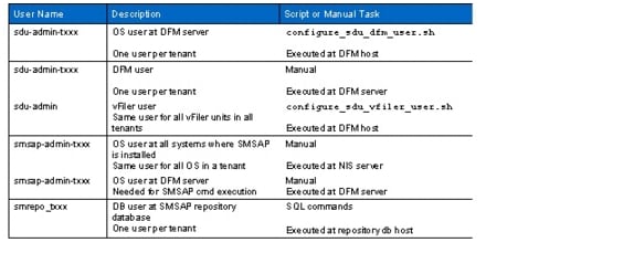
Figure 28 shows the different users that were created during the tenant provisioning workflow and the interaction between the various components.
Figure 28 Overview of user configuration during tenant provisioning
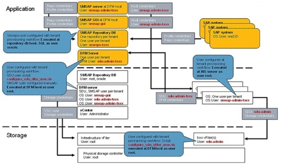
Initial Setup of a Tenant
At the time of tenant creation, the previously mentioned OS users, SDU, and repository users must be created. The following steps outline the required steps for tenant t002.
1.
Create a directory for config files in the infrastructure tenant (if it does not already exist):
# mkdir /mnt/data/conf
# chmod 700 /mnt/data/conf
Edit the password file /mnt/data/conf/t002-ntap-passwords.txt.
Example:
VFILER1="t002-1-prim secret!"
VFILER2="t002-1-bck secret!"
DFM="smt-dfm.mgmt.t001.company.corp secret!"
SMSAPREPO="t001-smrepo.mgmt.t001.company.corp secret!"
SMSAPOS="--- secret!"
2.
Encrypt the password file ./fp_encrypt.sh file t002.
3.
Copy the password file to /mnt/data/conf on the central service VM in the target tenant:
# scp /mnt/data/conf/t002-ntap-passwords.conf root@t002-0-lnx.t002.company.corp:/mnt/data/conf/t002-ntap-passwords.conf
4.
Create SMSAP user and set the password according to the password file (parameter <SMSAPOS>):
# useradd -d /home/smsap-admin-t002 -s /bin/false smsap-admin-t002
# passwd smsap-admin-t002
Update NIS so that all operating systems in the tenant can use the new user:
# /mnt/software/scripts/update_nis.sh
5.
Create local SMSAP user and set the password (parameter <SMSAPOS>):
# useradd -d /home/smsap-admin-t002 -m -s /bin/bash smsap-admin-t002
# passwd smsap-admin-t002
6.
Create OS user and set the password according to the password file. Create DFM user sdu-admin-t002 and configure role sdu-admin-role-t002:
First vFiler unit: configure_sdu_dfm_user.sh initial t002 <vFiler-name>
Each additional vFiler unit: configure_sdu_dfm_user.sh addvfiler t002 <vFiler-name>
7.
Create vFiler user sdu-admin and set the password according to the password file.
For each vFiler unit: configure_sdu_vfiler_user.sh t002 <vFiler-name>
8.
Create the tenant-specific tablespace and user. The user password is included in the password file (parameter <SMSAPREPO>).
The path to the data file depends on the layout of the repository database installation:
su - oracle
oracle@t001-smrepo:~> sqlplus / as sysdba
SQL> create tablespace repdata_t002 datafile '/oracle/REP/oradata/repdata_t002.dbf' size 100m;
SQL> create user smrepo_t002 identified by "PASSWORD" default tablespace repdata_t002;
SQL> grant connect, resource to smrepo_t002;
9.
# smsap repository create -repository -port 1521 -dbname REP -host t001-smrepo.mgmt.t001.company.corp -login -username smrepo_t002
Enter password for database connection smrepo_t002@t001-smrepo.mgmt.t001.company.corp:1521/REP: ********
[ INFO] SMSAP-20019: Set password for repository "smrepo_t002@REP/t001-smrepo.mgmt.t001.company.corp:1521" in user credentials for "root".
[ INFO] SMSAP-09202: Creating new schema as t002 on jdbc:oracle:thin:@//t001-smrepo.mgmt.t001.company.corp:1521/REP.
[ INFO] SMSAP-09205: Schema generation complete.
[ INFO] SMSAP-09209: Performing repository version INSERT.
Adding a vFiler Unit to a Tenant
When a vFiler unit is added to a tenant, the DFM user must get the rights to manage the new system. An SDU user must be added and configured at the new vFiler unit. All operating systems in the tenant must set the credentials for the new system.
The following steps provide examples for tenant t002.
1.
Edit the password file /mnt/data/conf/t002-ntap-passwords.txt and add a new entry for the additional vFiler unit.
2.
Encrypt the password file ./fp_encrypt.sh file t002.
3.
Copy the password file to /mnt/data/conf on the central service VM in the target tenant.
# scp /mnt/data/conf/t002-ntap-passwords.conf root@t002-0-lnx:/mnt/data/conf/t002-ntap-passwords.conf
4.
For each additional vFiler unit: configure_sdu_dfm_user.sh addvfiler t002 <vFiler-name>
5.
Create the vFiler user sdu-admin and set the password according to the password file:
For each vFiler unit: configure_sdu_vfiler_user.sh t002 <vFiler-name>
6.
Execute script set_sdu_credentials.sh to update SDU credentials.
Additional Steps Required to Work with a Second FlexPod Infrastructure
In order to work with a second FlexPod infrastructure, appropriate network setting must be made on all the Cisco Nexus 5548 switches and the uplink to the central switch. For details, refer to section, "Additional Steps for Adding a Second FlexPod Infrastructure."
OS Provisioning
SLES/RHEL and VMware
Figure 29 shows how the operating system is provisioned.
Figure 29
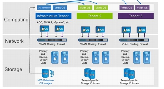
Several methods are available to provision a new OS into a tenant:
•
•
•
•
The following subsections describe these different methods. After an OS is deployed, an Automated OS Configuration is executed during system boot.
Manual Deployment Using the Rapid Cloning Utility
The following section lists the steps to provision a new VM or OS by using the NetApp Rapid Cloning Utility (RCU).
1.

2.

3.

4.

5.

6.
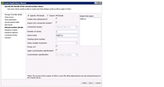
7.

8.

9.
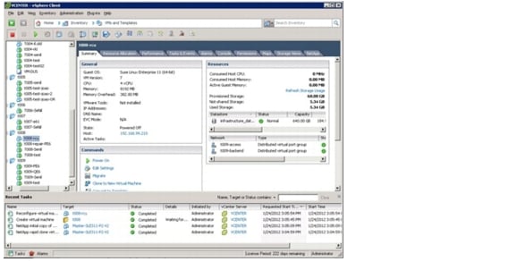
10.

11.
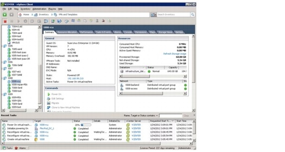
Manual Deployment Using the VMware Built-In Method
To provision a new VM, open the context menu of the desired template, select Deploy Virtual Machine, and follow the steps in this wizard. Do not choose to start the VM automatically. When the deployment has finished, execute steps 9 through 11 of the previous procedure.
Deployment Using the Script DeployNewVm_w_rcu.ps1
The PowerShell script DeployNewVm_w_rcu.ps1 is used to provision the OS image. The script uses cloning based on RCU or VSC.
In the current version, the following parameters are hard coded:
•
•
•
•
DeployNewVm_w_rcu.ps1 <VM Name> <Tenant ID> <Template Name>
Where:
–
–
–
The script executes the following steps:
1.
2.
3.
4.
5.
–
–
6.
Deployment Using the Script DeployNewVm.ps1
The PowerShell script DeployNewVm.ps1 is used to provision the OS image. The script uses native VMware-based cloning.
In the current version, the following parameters are hard coded:
•
•
DeployNewVm.ps1 <VM Name> <Tenant Name> < Template Name>Where:
–
–
–
The script executes the following steps:
1.
2.
3.
4.
5.
–
–
6.
Automated OS Configuration
After the OS template-cloning process is finished, all necessary tenant-specific parameters are configured automatically.
•
•
•
There is no need for further configuration at the OS level, and the OS can be used immediately to run an SAP system. Section 9, "SAP System Provisioning," describes this process in detail.
During the boot process, the DHCP server configures the host name and the interfaces for the user and back-end LAN, as well as the default route.
The following example (for a host in tenant 2) shows the configuration that should be available:
t002-40-lnx:~ # ifconfigeth0 Link encap:Ethernet HWaddr 00:50:56:A6:00:46inet addr:192.168.2.90 Bcast:192.168.2.255 Mask:255.255.255.0inet6 addr: fe80::250:56ff:fea6:46/64 Scope:LinkUP BROADCAST RUNNING MULTICAST MTU:1500 Metric:1RX packets:5265 errors:0 dropped:0 overruns:0 frame:0TX packets:6328 errors:0 dropped:0 overruns:0 carrier:0collisions:0 txqueuelen:1000RX bytes:1202537 (1.1 Mb) TX bytes:1416674 (1.3 Mb)eth1 Link encap:Ethernet HWaddr 00:50:56:A6:00:47inet addr:192.168.102.90 Bcast:192.168.102.255 Mask:255.255.255.0inet6 addr: fe80::250:56ff:fea6:47/64 Scope:LinkUP BROADCAST RUNNING MULTICAST MTU:1500 Metric:1RX packets:6235877 errors:0 dropped:0 overruns:0 frame:0TX packets:4234493 errors:0 dropped:0 overruns:0 carrier:0collisions:0 txqueuelen:1000RX bytes:8355884612 (7968.7 Mb) TX bytes:1661872038 (1584.8 Mb)t002-40-lnx:~ # hostnamet002-40-lnxt002-40-lnx:~ # netstat -nrKernel IP routing tableDestination Gateway Genmask Flags MSS Window irtt Iface192.168.102.0 0.0.0.0 255.255.255.0 U 0 0 0 eth1192.168.2.0 0.0.0.0 255.255.255.0 U 0 0 0 eth0169.254.0.0 0.0.0.0 255.255.0.0 U 0 0 0 eth0127.0.0.0 0.0.0.0 255.0.0.0 U 0 0 0 lo0.0.0.0 192.168.2.1 0.0.0.0 UG 0 0 0 eth0In addition, the rc script flexpod_config is executed during the boot process. It is part of the Linux OS and performs the following tasks (example with company.corp as the domain name):
•
software.company.corp:/vol/software to /mnt/software
•
"$TENANT"-1-bck:/vol/"$TENANT"_backup/data to /mnt/backup
•
"$TENANT"-1-prim:/vol/"$TENANT"_share/data to /mnt/data
After the OS is booted, the following NFS mounts should be available (example with company.corp as the domain name and tenant t002):
software.company.corp:/vol/software167772160 57500096 110272064 35% /mnt/softwaret002-1-bck:/vol/t002_backup/data31456896 4224 31452672 1% /mnt/backupt002-1-prim:/vol/t002_share/data31457280 320 31456960 1% /mnt/dataIn addition, this script starts the script /mnt/software/scripts/set_sdu_credentials.sh in the background to set the SDU and DFM passwords. The script waits until the SDU daemon is started and then sets the credentials for the DFM server and all vFiler units that are configured in the password file.
About five minutes after the SDU daemon has been started, the SDU configuration should be available, as shown in the following example for a host in tenant 2 and domain name company.corp:
t002-39-lnx:/sapmnt/PE6/exe # snapdrive config listusername appliance name appliance type----------------------------------------------------------------sdu-admin t002-1-prim StorageSystemsdu-admin t002-1-bck StorageSystemsdu-admin-t002 smt-dfm.mgmt.t001.company.corp DFMOS Provisioning SLES on Bare Metal
Create a Service Profile from a Service Profile Template
Log in to "var_ucsm_A_hostname" or "var_ucsm_B_hostname".
create service-profile t002-lnx-01set src-templ-name linux_ascope vnic vNIC_Acreate eth-if t002-accessset default-net yescommit-bufferexitdelete eth-if defaultcommit-bufferexitexitscope vnic vNIC_Bcreate eth-if t002-backendset default-net yescommit-bufferexitdelete eth-if defaultcommit-bufferexitassociate server-pool Infa_Poolcommit-bufferexitcommit-bufferConfigure the SAN Zoning
Configure the Cisco Nexus 5548 switches for the new servers as described in section, "Cisco Nexus 5548 Deployment Procedure: Part II," in TR-3939: VMware vSphere Built on FlexPod Implementation Guide.
Choose a zone name and use the worldwide port names (WWPNs) of the vHBAs of the new server for the configuration (instead of ESXi hosts).
Configure the Storage
Configure the igroups and create the logical unit numbers (LUNs) for the new servers as described in section, "NetApp FAS3210 A Deployment Procedure: Part II," in TR-3939: VMware vSphere Built on FlexPod Implementation Guide.
Choose a name for the igroups and LUNs and assign the WWPNs of the vHBAs of the new server to the igroups. Create the LUNs with a size of 60GB instead of 10GB.
Install SLES 11 SP2
As a prerequisite, before the server installation can be started, the NetApp storage and SAN zoning must be configured completely. The following section describes the steps required for the initial OS installation.
1.
2.
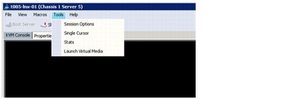
3.
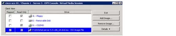
4.
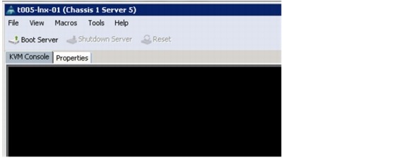
5.
Note
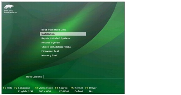
Post-Installation Steps
The post-installation steps for a bare metal SuSE installation are identical to the configuration steps that are required for the creation of a virtual machine OS template. For more information, refer to sections "Installation of Additional Software Components" and "SMSAP Installation and Configuration."
RHEL OS Provisioning on Bare Metal
Create a Service Profile from a Service Profile Template
Log in to "var_ucsm_A_hostname" or "var_ucsm_B_hostname".
create service-profile t005-lnx-02set src-templ-name linux_ascope vnic vNIC_Acreate eth-if t005-accessset default-net yescommit-bufferexitdelete eth-if defaultcommit-bufferexitexitscope vnic vNIC_Bcreate eth-if t005-backendset default-net yescommit-bufferexitdelete eth-if defaultcommit-bufferexitassociate server-pool Infa_Poolcommit-bufferexitcommit-bufferConfigure SAN Zoning
Configure the Cisco Nexus 5548 switches for the new servers as described in section, "Cisco Nexus 5548 Deployment Procedure: Part II," in TR-3939: VMware vSphere Built on FlexPod Implementation Guide.
Choose a name for the zone name and use the WWPNs of the vHBAs of the new server for the configuration (instead of ESXi hosts).
Install RHEL 5 with the Kickstart Option
As a prerequisite before the server installation can be started, the NetApp controllers and SAN zoning must be configured completely, as detailed in the following steps.
1.
2.

3.
4.

5.
6.
7.

8.
Differences With a Second FlexPod Infrastructure
The changes described in the following subsections apply when you provision an operating system in an environment that has more than one FlexPod infrastructure.
Provisioning Virtual Machines
In order to improve performance, it is assumed that each infrastructure defines its own volumes for infrastructure datastores that host the virtual machines. NetApp recommends creating an OS- and tenant-specific services template for each infrastructure as a copy master in the same datastore. No further restrictions apply.
OS Provisioning SLES on Bare Metal
SAN storage is usually local to the data center. Therefore a new server is bound to SAN resources in its own data center. After the server is installed, it is a part of a tenant and therefore can connect even to datastores from a different data center.
OS Provisioning RHEL on Bare Metal
The same restrictions described previously also apply to RHEL on bare metal.
OS Provisioning SLES Using PXE boot
No restrictions apply; however, NetApp recommends using local data center resources for the NFS root file system.
SAP System Provisioning
This section describes the steps to prepare for the installation of a new SAP system. The following provides an overview of these steps.
1.
2.
3.
4.
5.
6.
7.
Preparation
Prepare the SID-Specific Configuration File
Before starting the provisioning process, a SID-specific configuration file must be provided. For example, t002-PE6.conf is the name of the configuration file for SID=PE6 in tenant 2. The configuration file must be stored at /mnt/data/conf in the infrastructure tenant. After adjusting all parameters as described in section, "SID-Specific Configuration File," the configuration file must be copied to /mnt/data/conf in the target tenant.
Example: For tenant t002 and the tenant-specific services host with IP address 192.168.2.50:
scp t002-PE6.conf 192.168.2.50:/mnt/data/conf/Provision a New OS
The new OS image is deployed as described in section, "OS Provisioning."
DNS and NIS Configuration
Some information must be added to the DNS and NIS configuration for the new SAP system. The following describes the steps to add the required information.
1.
•
•
This can be done by using the script /mnt/software/scripts/createSAPuser.sh.
Usage: createSAPuser.sh <user_type> <SID> <user_id> <group> [<additional_groups> [<password>]]
<user_type> : {adm|ora}, adm = <sid>adm user, ora = ora<sid> user
<SID> : SAP System ID
<user_id> : user ID of the new user
<group> : group ID or name of the primary group of the new user
<additional_groups> : (opt.) list of additional groups (comma separated list of names)
<password> : (opt.) password for the new user
Note
/mnt/software/scripts/createSAPuser.sh adm pe6 1001 sapsys 'sapinst,dba,oper' 'myPassword!'
/mnt/software/scripts/createSAPuser.sh ora pe6 1002 dba 'sapinst,oper' 'myPassword!'
2.
For example:
/mnt/software/scripts/addSAPservicefromConf.sh /mnt/data/conf/t002-PE6.conf
3.
For example:
/mnt/software/scripts/addDNSHostnamefromConf.sh /mnt/data/conf/t002.conf /mnt/data/conf/t002-PE6.conf
4.
a.
b.
Storage Provisioning
To provision storage, run the commands in the following steps on the NetApp DFM host. These steps can be executed either manually or by using the example script provisionSapStorage.sh.
This script must be executed at the DFM host:
/mnt/software/scripts/provisionSapStorage.sh /mnt/data/conf/t002.conf
/mnt/data/conf/t002-PE6.conf
1.
dfpm dataset create -v <provisioning policy> -r < primary vFiler name> <<tenant>_sapdata_<SID> >
For example: dfpm dataset create -v Default -r t002-1-prim t002_sapdata_PE6
2.
dfpm dataset respool add <<tenant>_sapdata_<SID> > <primary resource pool>
For example: dfpm dataset respool add t002_sapdata_PE6 filer14a
3.
dfpm dataset provision -n sapdata_<SID> -s <size, e.g., 150g> -e nfs -w all -N no -a 0 -S sys <<tenant>_sapdata_<SID> >
For example: dfpm dataset provision -n sapdata_PE6 -s 150g -e nfs -w all -N no -a 0 -S sys t002_sapdata_PE6
4.
dfpm dataset create -v <provisioning policy> -r <primary vFiler name> <<tenant>_saplog_<SID> >
For example: dfpm dataset create -v Default -r t002-1-prim t002_saplog_PE6
5.
dfpm dataset respool add <<tenant>_saplog_<SID> > <primary resource pool>
For example: dfpm dataset respool add t002_saplog_PE6 filer14a
6.
dfpm dataset provision -n saplog_<SID> -s <size, e.g. 10g> -e nfs -w all -N no -a 0 -S sys <<tenant>_saplog_<SID> >
For example: dfpm dataset provision -n saplog_PE6 -s 50g -e nfs -w all -N no -a 0 -S sys t002_saplog_PE6
7.
dfpm dataset destroy -f <<tenant id>_saplog_<SID> >
For example: dfpm dataset destroy -f t002_saplog_PE6
8.
dfm run cmd <primary vFiler name> vol options <tenant id>_saplog_<SID> nosnap on
For example: dfm run cmd t002-1-prim vol options t002_saplog_PE6 nosnap on
9.
dfm run cmd <primary vFiler name> vol options <tenant id>_saplog_<SID> nosnapdir on
For example: dfm run cmd t002-1-prim vol options t002_saplog_PE6 nosnapdir on
10.
dfpm dataset destroy -f <<tenant id>_sapdata_<SID> >
For example: dfpm dataset destroy -f t002_sapdata_PE6
11.
dfm run cmd <primary vFiler name> vol options <tenant id>_sapdata_<SID> nosnap on
For example: dfm run cmd t002-1-prim vol options t002_sapdata_PE6 nosnap on
12.
dfm run cmd <primary vFiler name> vol options <tenant id>_sapdata_<SID> nosnapdir on
For example: dfm run cmd t002-1-prim vol options t002_sapdata_PE6 nosnapdir on
Creating Subdirectories
After the storage volumes have been provisioned, several subdirectories must be created within these volumes. These steps can be executed either manually or by using the script fp_sap_mountpoints.sh. The script must be executed at the tenant-specific services VM in the target tenant of the SAP system. For example:
/mnt/software/scripts/fp_sap_mountpoints.sh /mnt/data/conf/t002.conf
/mnt/data/conf/t002-PE6.conf
The following section describes the manual commands to create the necessary subdirectories.
1.
Mount <vFiler>:/vol/<tenant>_sapdata_<SID>/sapdata_<SID> /mnt/sapdata
For example:
Mount t002-1-prim:/vol/t002_sapdata_PE6/sapdata_PE6 /mnt/sapdata
2.
Mount <vFiler>:/vol/<tenant>_saplog_<SID>/saplog_<SID> /mnt/saplog
For example:
Mount t002-1-prim:/vol/t002_saplog_PE6/saplog_PE6 /mnt/saplog
3.
mkdir /mnt/sapdata/sapdata1
mkdir /mnt/sapdata/sapdata2
mkdir /mnt/sapdata/sapdata3
mkdir /mnt/sapdata/sapdata4
4.
mkdir /mnt/saplog/saphome
mkdir /mnt/saplog/saphome/<sid>adm
mkdir /mnt/saplog/sapusr
mkdir /mnt/saplog/sapmnt
mkdir /mnt/saplog/oracle
mkdir /mnt/saplog/oracle/stage
mkdir /mnt/saplog/oracle/oraInventory
mkdir /mnt/saplog/oracle/diag
mkdir /mnt/saplog/oracle/checkpoints
mkdir /mnt/saplog/oracle/<SID>
5.
umount /mnt/sapdata
6.
umount /mnt/saplog
Mounting File Systems and Configuring the IP Alias
The script fp_sap_system.sh is used to mount the necessary file systems and configure the IP alias. This script is executed at the host where the SAP system is to be installed or migrated with the following command:
/mnt/software/scripts/fp_sap_system.sh <tenant_parameter_file>
<SID_parameter_file> startmountonly
The script executes the following tasks:
•
•
•
•
SAP System Installation with SAPinst
The SAP system is installed by using SAPinst. To install an SAP system using virtual host names (necessary to move systems between hosts and for SAP ACC integration), the SAP instances must be installed in the following order (select the Distributed System option):
1.
2.
3.
Place Oracle Control Files
To use SMSAP for fast restore, the location of the control files (and its copies) is of imminent importance and must not be in the same volume as the SAP database files. If you use a standard SAP installation procedure, the control files are placed in the /oracle/SID/origlogA, /oracle/SID/origlogB, and /oracle/SID/sapdata1 file systems.
The control file in the sapdata1 file system conflicts with the SnapManager requirements for separating the control files and datafiles into separate volumes and must be adjusted to allow for fast restore capability.
In the case of a new SAP install, you can adjust the location of the control files by using SAPINST during the SAP installation process and move the control file normally placed in the sapdata1 file system (that is, the data volume) to the log volume. However, in the case the SAP system was already installed, you must move the control file out of that file system to allow for fast restores when using SnapManager.
SAP System Post Installation Tasks
Oracle software is installed during a standard system installation. As part of the standard installation, the Oracle client installation is also selected.
Oracle Client—Template Update
The Oracle client software is already installed as part of the OS template. After an installation or upgrade, check whether the Oracle installer has added a new release or changed the current client release during the SAP installation process.
If there is a change, NetApp recommends transferring the entire Oracle client software and folder and creating a new version of the OS template, which can be used to deploy a new OS on which the installed SAP system can run.
There are several ways to accomplish this. The following describes a three-step procedure. For more information about maintaining the OS template, refer to section, "Linux Template Creation."
1.
# cd /oracle
# tar -cvzf /mnt/data/oraclient_t002_pe6.tgz client
2.
# cd /mnt/data
# scp oraclient_t002_pe6.tgz client
192.168.2.50:/mnt/data/oraclient_t002_pe6.tgz .
3.
# cd /oracle
# tar -xvzf /mnt/data/oraclient_t002_pe6.tgz
Follow the steps described in section 6.2 to create a new OS template that includes the new Oracle client software.
Configuring Backup Services for SAP Systems
Backup services can be configured for newly installed or migrated SAP systems as well as for SAP systems that have been created as a system copy with SMSAP.
If backup services have been configured for SAP systems based on a SMSAP system copy, several additional steps must be taken before refreshing the SAP system again. See section 13.2, "System Refresh."
The SAP Br*tools, in combination with SnapManager for SAP and Protection Manager, are used to back up the SAP systems.
•
•
•
Figure 30 shows how SMSAP and Protection Manager work together with the SAP Br*tools.
Figure 30 Overview of backup services

The following are the steps to configure backup services.
1.
2.
3.
4.
5.
6.
7.
8.
9.
10.
Users and Credentials
Figure 31 shows the users and credentials that are set during the backup services configuration. The SMSAP profile for the SAP system is created as user smsap-admin-xxx in the DFM server. In the database server of the SAP system, credentials are set as user oraSID for the SMSAP repository and the SMSAP profile of the SAP system.
Figure 31 User and credentials for backup service configuration
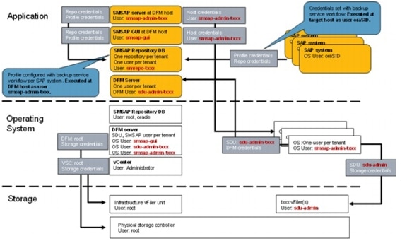
Protection Manager Protection Policies
Typically, more than one protection policy is defined to allow different retention policies for different SAP system classes or customer-defined SLAs.
New protection policies are typically created as copies from existing policies. For example, the new protection policy is created as a copy of the backup policy. The new policy defines the retention policy for the secondary storage as well as the schedules for SnapVault updates to the secondary storage. Figure 32 shows an example using the SMSAP_Backup protection policy.
Figure 32 Defining the new protection policy
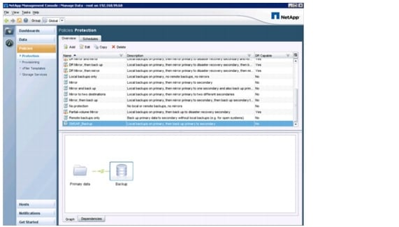
Local Snapshot images are created by SMSAP, so the local backup schedule is set to (none), as shown in Figure 33.
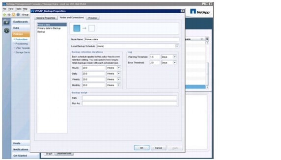
The schedule for SnapVault software updates is configured in the Primary Data to Backup panel. The example in Figure 34 shows an hourly SnapVault software update schedule.

The retention policy at the secondary storage is defined in the Backup panel. In the example shown in Figure 35, a two-week retention policy for daily backups has been defined.
Figure 33 Defining the retention policy at the secondary storage

SMSAP Profile Creation
All SMSAP profiles for the SAP systems are created at the DFM host as user smsap-admin-txxx.
•
•
•
•
The profile name must include the tenant ID; for example PE6-T002. Otherwise, duplicate SIDs cannot be handled in a single SMSAP GUI, even if the SID is in a different tenant.
smt-dfm:/mnt/software/scripts # su - smsap-admin-t002Example for a profile without data protection:
smsap-admin-t002@smt-dfm:~> smsap profile create -profile PE6-T002
-profile-password ucs4sap! -repository -dbname REP -host
t001-smrepo.mgmt.t001.company.corp -port 1521 -login -username smrepo_t002
-database -dbname PE6 -host dbPE6.t002.company.corp -osaccount oraPE6 -osgroup
dba -comment "ERP PE6"
Enter password for database connection smrepo_t002@t001-smrepo.mgmt.t001.company.corp:1521/REP: ********[ INFO] SMSAP-20019: Set password for repository "smrepo_t002@REP/t001-smrepo.mgmt.t001.company.corp:1521" in user credentials for "smsap-admin-t002".[ INFO] SMSAP-20020: Set password for profile "PE6-T002" in user credentials for "smsap-admin-t002".Enter password for user smsap-admin-t002@dbPE6.t002.company.corp: ********Operation Id [402882e031bdc0ba0131bdc0bd4f0009] succeeded.smsap-admin-t002@smt-dfm:~>Example for a profile with data protection:
smsap-admin-t002@smt-dfm:~> smsap profile create -profile PE6-t002
-profile-password ucs4sap! -repository -dbname REP -host
t001-smrepo.mgmt.t001.company.corp -port 1521 -login -username smrepo_t002
-database -dbname PE6 -host dbpe6.t002.company.corp -osaccount orape6 -osgroup
dba -comment "ERP PE6" -protect -protection-policy SMSAP_BACKUP
[ INFO] SMSAP-20020: Set password for profile "PE6-t002" in user credentials for "smsap-admin-t002".Enter password for user smsap-admin-t002@dbpe6.t002.company.corp: ********Operation Id [402882be31d361d30131d361d5d0000a] succeeded.smsap-admin-t002@smt-dfm:~>Data Protection Configuration
The following are the steps to configure data protection.
1.

2.

3.
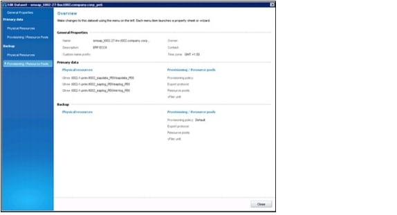
4.

5.

Note
6.

7.
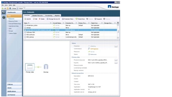
Note
Cloning From Secondary Storage
When cloning from secondary storage, you must complete the following step to set the NFS exports for the target volumes of the SMSAP backup. These target volume names have the general format: smsap_<hostname of database host>_<sid>_backup-<no>.
For example, for system PE6 in tenant 2, where the volume names are:
•
•
For each volume the following command must be executed at the DFM host:
dfm run cmd t002-1-bck exportfs -p sec=sys,rw,anon=0 /vol/<volname>Where the backup vFiler unit name is t002-1-bck.
Brbackup and Brarchive Configuration
Brbackup is used to create local Snapshot copy backups at the primary storage using the configuration file $ORACLE_HOME/dbs/initSID_hourly.sap. These backups are not replicated to the secondary storage as configured in the $ORACLE_HOME/dbs/initSID_hourly.utl file. A second configuration file is used to configure daily backups, which are replicated to the secondary storage.
Archive log backups are produced using Brarchive with the backup_device_type disk instead of using SMSAP. The destination for the archive log backups is a mountpoint at the secondary storage. Brconnect is used to delete the archive logs at the secondary storage based on a configurable retention policy in $ORACLE_HOME/dbs/initSID.sap.
Table 7 shows a configuration example for a system with SID=PE6 and the profile name PE6-T002.
Table 7 Backint and Br*tools configuration
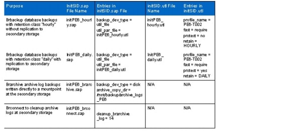
SMSAP credentials must be set for user orasid. After the credentials are set for user orasid, both users orasid and sidadm can execute Br*tools commands from the command line or the SAP DBA Planning Calendar. (Sticky bits must be set correctly for the Br*tools.)
The following example shows the configuration for:
•
•
•
# su - oraPE6T002-17-lnx:oraPE6 51> smsap credential set -repository -dbname REP -host t001-smrepo.mgmt.t001.company.corp -login -username smrepo_T002 -port 1521Enter password for database connection smrepo_T002@t001-smrepo.mgmt.t001.company.corp:1521/REP: ********[ INFO] SMSAP-20019: Set password for repository "smrepo_T002@REP/t001-smrepo.mgmt.t001.company.corp:1521" in user credentials for "oraPE6".T002-17-lnx:oraPE6 52> smsap profile sync -repository -dbname REP -host t001-smrepo.mgmt.t001.company.corp -port 1521 -login -username smrepo_T002[ INFO] SMSAP-20010: Synchronizing mapping for profiles in repository "smrepo_T002@REP/t001-smrepo.mgmt.t001.company.corp:1521".[ INFO] SMSAP-20011: Loaded mapping for profile "PE6-T002".T002-17-lnx:oraPE6 53> smsap credential set -profile -name PE6-T002Enter password for profile PE6-T002: ********[ INFO] SMSAP-20020: Set password for profile "PE6-T002" in user credentials for "oraPE6".T002-17-lnx:oraPE6 54>After the configuration files have been adapted, database and archive log backups can be scheduled using the SAP DBA Planning Calendar (DB13).
Naming Conventions and Prerequisites
SAP Service Names
The following are the naming conventions for the SAP services names (virtual host names):
•
•
•
•
•
•
•
•
•
•
•
•
Note
Storage Layout
Table 8 lists the storage layout for ABAP and the Java central system. The file system /oracle/client is part of the operating system and is available with the OS boot. Additional subdirectories under /oracle may be necessary, depending on the Oracle release that has been used:
•
•
Table 8 Storage layout for ABAP and Java central system

Note
Description of Configuration Files
Most of the scripts that are used to administer and set up the landscape use one or more configuration files. These configuration files define parameters, using a shell script-like syntax (parameter-name = parameter-value), that are used in the scripts and templates.
The following configuration files exist:
•
•
•
•
The configuration files for all tenants must be present on a share /mnt/data/conf in the infrastructure tenant, and each tenant must access only its specific configuration files on a tenant-specific share (same mountpoint /mnt/data/conf). It is the task of the administrator to copy the relevant configuration files into the tenant (after changes have been made).
Tenant-Specific Configuration File
The tenant-specific configuration file tnnn.conf contains parameters for tenant configuration. It includes general information such as tenant ID and tenant name, as well as tenant-related network, storage, DNS, DHCP, NIS, and VMware settings.
The parameter file tnnn.conf must be stored in the directory /mnt/data/conf in the infrastructure tenant and also must be copied to /mnt/data/conf on the managed tenant.
Following is an example of a tenant configuration file for tenant id t042:
# V2.07# FlexPod V2.07 - parameter file for tenant t042# ================================================# The Tenant specific configuration file is required for several scripts# to provide all the necessary input variables. Since some of the scripts# need to run within the infrastructure tenant, others within the tenant itself,# this config file needs to be present in both locations at the following folder# /mnt/data/conf# It is considered that you maintain the values within the infrastructure tenant and copy# the updated version into the tenant (for example using the tenant specific# services host: example: scp t042.conf root@192.168.42.50:/mnt/data/conf/# The configuration file is separated into several parameter sections. Each section starts# with a documentation on how to use the parameters## Version history# ---------------# V2.01 - final adaptions dhcp# V2.02 - add dnsvHostLow, dnsvHostHigh# V2.03 - add storage vars to support create_vfiler script# V2.04 - change dns relay to 99.50# V2.05 - Set encryption_key# V2.06 - Include Vars to address SMSAP Repository# V2.07 - Included vfiler template and dns IP backend# general# --------# tenantId= internal ID for refferencing the Tenant :# tenantName= name for this tenant (often same as tenant Id)# Note: With the current release tenantID# must have the following format: tnnn# e.g. t032 for tenant 32# EncryptKey= Key for encrypting the passwords# smsapRepositoryHostname= SMSAP Repository hostname# smsapRepositoryPort= Listener port of repository database# smsapRepositoryService= Database SID of repository database#tenantId=t042tenantName=t042EncryptKey=GeheimsmsapRepositoryHostname=t001-smrepo.mgmt.t001.company.corpsmsapRepositoryPort=1521smsapRepositoryService=REP# network# -------# vlanIdAccess= Vlan Id for the Access & Backend lan.# vlanIdBackend= It is usally 2000+<nn> and 3000+<nn># networkAccess=192.168.42.0 Network for the access LAN# netmaskAccess=255.255.255.0 Netmask for the access LAN# networkBackend=192.168.142.0 Network for the backend LAN# netmaskBackend=255.255.255.0 Netmask for the backend LAN# interfaceAccess=eth0 Interface for Access LAN (typically eth0)# interfaceBackend=eth1 Interface for Backend LAN# defaultGW=192.168.42.1 Default Gateway# mtusize=9000 ip MTU size for the storage network#vlanIdAccess=2042vlanIdBackend=3042networkAccess=192.168.42.0netmaskAccess=255.255.255.0networkBackend=192.168.142.0netmaskBackend=255.255.255.0interfaceAccess=eth0interfaceBackend=eth1defaultGW=192.168.42.1mtusize=9000# vmware# -------# vmNetworkAccess= Name of the network lable within Vmware VC# vmNetworkBackend= Name of the network lable within Vmware VC# vmTenantFolder= Folder name for the tenant#vmNetworkAccess=t042-accessvmNetworkBackend=t042-backendvmTenantFolder=t042# storage# -------# primaryResourcePool_1= Name of primary resource pool used for the first# primary vfiler in a tenant.# primaryResourcePool_2= Name of primary resource pool used for the second# primary vfiler in a tenant.# Note: A tenant can use more than one vfiler in# different resource pools to allow load# distribution to different physical storage controlles## secondaryResourcePool_1= Name of the secondary resource pool used for# the backup vfiler. Currently only one per tenant.# primaryProvisioningPolicy_1= Provisioning policy for the first vfiler# primaryProvisioningPolicy_2= Provisioning policy for the second vfiler# secondaryProvisioningPolicy_1= Provisioning policy for the backup vfiler# vFilerTemplate= Name of the vfiler template that is created manually# or created by the automation scripts# virtualInterface= Name of interface on the storage controller where the# vfilers will be assigned to# primVfilerIp_1= IP address of the first primary vfiler in a tenant# primVfilerIp_2= IP address of the second primary vfiler in a tenant# secVfilerIp_1= IP address of the backup vfiler in a tenant 1# primVfilerName_1= Name of the first primary vfiler# primVfilerName_2= Name of the second primary vfiler# secVfilerName_1= Name of the backup vfiler# Note: With the current release the vfiler names# must have the following format:# <tnnn>-<n>-<prim> for primary vfilers# <tnnn>-<n>-<bck> for backup vfilers# centralVolumeName= Name of the central shared volume# backupVolumeName= Name of the backup volume# Note: With the current release the volume names# must have the following format:# <tnnn>_share for the central volume# <tnnn>_backup for the backup volumeprimaryResourcePool_1=storageAprimaryResourcePool_2=storageCsecondaryResourcePool_1=storageDprimaryProvisioningPolicy_1=NAS_SASprimaryProvisioningPolicy_2=NAS_SASsecondaryProvisioningPolicy_1=SEC_SATAvFilerTemplate=t042-vfiler-templatevirtualInterface=vif0primVfilerIp_1=192.168.142.10primVfilerIp_2=192.168.142.12secVfilerIp_1=192.168.142.11primVfilerName_1=t042-1-primprimVfilerName_2=t042-2-primsecVfilerName_1=t042-1-bckcentralVolumeName=t042_sharebackupVolumeName=t042_backup# dns# ---# For larger deployments there could be multiple DNS Servers#(indicated via suffix _1 or _2)for dns Ip's and Name## dnsIp_1= Access LAN IP of the tenant specific# service VM (DHCP, DNS, NIS)# dnsBkndIp_1= Backend LAN IP of the tenant specific# service VM (DHCP, DNS, NIS)# dnsName_1= DNS name for the of the tenant specific# service VM (DHCP, DNS, NIS)# dnsRelayServer= The IP of the infrastructure tenant DNS# server that is used as relay server# dnsDomainAccess= DNS domain name for access LAN# dnsDomainBackend= DNS domain name for backend LAN# dnsvHostLow= IP address range for virtual hostnames that will# dnsvHostHigh= be configured for SAP services#dnsIp_1=192.168.42.50dnsBkndIp_1=192.168.142.50dnsName_1=t042-0-lnxdnsRelayServer=192.168.99.50dnsDomainAccess=t042.company.corpdnsDomainBackend=bknd.t042.company.corpdnsvHostLow=100dnsvHostHigh=199# dhcp# ----# The DHCP seetings will be configured based on templates.# These templates will use parameters specified in the# DNS DHCP and NIS section. The dhcpRangeLow/High parameters# are used to define the range that is used when assigning# ip's to newly deployed OS. This range must not overlap with# the dnsvHost range that is configured above for the virtual ip# addresses for the SAP services.#dhcpRangeLowAccess=192.168.42.61dhcpRangeHighAccess=192.168.42.99dhcpRangeLowBackend=192.168.142.61dhcpRangeHighBackend=192.168.142.99# nis# ----# More than one NIS Server could be specified (Suffix _1, _2).# To specify a NIS server ip, Name and Domain Name must be given.# Note: With the current version DNS, DHCP and NIS are running on the# same host. Therefore nisIP and dnsIP are the samenisIp_1=192.168.42.50nisName_1=t042-0-lnxnisDomain=t042.company.corp.nisSID-Specific Configuration File
The SID-specific configuration file tnnn-SID.conf includes parameters for a specific SAP system in a specific tenant. It includes general information such as SAP SID and system type, as well as SID-related storage settings. The config file uses sections for each SAP service; for example, ci or scs. Service sections that are not needed can remain in the config file. The scripts configure only the services that are included in the services list.
The parameter file tnnn-SID.conf must be stored in the directory /mnt/data/conf in the infrastructure tenant and also must be copied to the /mnt/data/conf directory in the managed tenant.
Example of SID PP7 in tenant t002:
(Additional subdirectories under /oracle may be necessary, depending on the Oracle release.)
•
•
# Configuration file to define all paramteters for an SAP system.# The configuration file is required for several scripts# to provide all the necessary input variables. Since some of the scripts# need to run within the infrastructure tenant, others within the tenant itself,# this config file needs to be present in both locations at the following folder# /mnt/data/conf. # It is considered that you maintain the values within the# infrastructure tenant and copy the updated version into the tenant# (for example using the tenant specific services host:# example: scp t042.conf root@192.168.42.50:/mnt/data/conf/# The configuration file is separated into several parameter sections.# Each section starts with a documentation on how to use the parameters## V202 Tnnn-SID.conf# parameter file for SAP system PP7 in tennat t002# V203 Adapted to new layout. Only one qtree at tnnn_saplog_SID volume# SAP system# ----------# systemid= SID of the SAP system in upper case# low_systemid= SID in lower case# services= List of service of the SAP system# For abap system: "db ci"# For java system: "db scs jc smd"# ci_instanceno= Instance number of central instance# scs_instanceno= Instance number of scs# jc_instanceno= Instance number of jc# smd_instanceno= Instance number of smd# datavolumeSize= Size of data volume# logvolumeSize= Size of log volume# persistent= true or false. If true mounts will be written to# /etc/fstab. Should be normally set to false.# primVfilerName= Name of the vfiler, where the SAP should run.# This vfiler must exist in the tenant and must be# configured in the tenant configuration file.# primRespool= The resource pool must be the same as configured# in the tenant configuration file for this vfiler.# primProvProfile= Could be any of the NAS provisioning policies# as long as the defined resource label within the# policy is also defined within the resource pool.# backupVfilerName= Name of the backup vfiler# backupRespool= The resource pool must be the same as configured# in the tenant configuration file for this vfiler.# backupProvProfile= Could be any of the SEC provisioning policies# as long as the defined resource label within the# policy is also defined within the resource pool.systemid=PP7low_systemid=pp7services="db scs jc smd"ci_instanceno=00scs_instanceno=41jc_instanceno=40smd_instanceno=98datavolumeSize=200glogvolumeSize=150gpersistent=falseprimRespool="$primaryResourcePool_1"backupRespool="$secondaryResourcePool_1"primProvProfile="$primaryProvisioningPolicy_1"backupProvProfile="$secondaryProvisioningPolicy_1"primVfilerName="$primVfilerName_1"backupVfilerName="$secVfilerName_1"# Volume names#--------------# Will be generated based on above configuration and paramters# in tenant configuration file.datavolume=${tenantId}_sapdata_${systemid}datavolqtree="sapdata_$systemid"datavolume_qtree_01="sapdata_$systemid $datavolumeSize"logvolume=${tenantId}_saplog_${systemid}logvolqtree="saplog_$systemid"logvolume_qtree_01="saplog_$systemid $logvolumeSize"# SAP instance db#----------------# Database service specific configuration. Will be generated based on above# configuration and paramters in tenant configuration file.# db_installationhost= Virtual hostname of database service# db_servicetype= Serivce type is always .db. for databases# db_instanceno= Not used# db_mountlist_1= List of mounts for the database service# db_mountlist_2= Note: The mountlist is adapted based on the# parameter in this file and the tenant# configuration file using the corresponding# parameters.db_installationhost=db$low_systemiddb_servicetype=dbdb_instanceno=db_mountlist_1="$primVfilerName:/vol/$logvolume/$logvolqtree/oracle/$systemid ==> /oracle/$systemid"db_mountlist_2="$primVfilerName:/vol/$logvolume/$logvolqtree/oracle/stage ==> /oracle/stage"db_mountlist_3="$primVfilerName:/vol/$logvolume/$logvolqtree/oracle/oraInventory ==> /oracle/oraInventory"db_mountlist_4="$primVfilerName:/vol/$datavolume/$datavolqtree/sapdata1 ==> /oracle/$systemid/sapdata1"db_mountlist_5="$primVfilerName:/vol/$datavolume/$datavolqtree/sapdata2 ==> /oracle/$systemid/sapdata2"db_mountlist_6="$primVfilerName:/vol/$datavolume/$datavolqtree/sapdata3 ==> /oracle/$systemid/sapdata3"db_mountlist_7="$primVfilerName:/vol/$datavolume/$datavolqtree/sapdata4 ==> /oracle/$systemid/sapdata4"db_mountlist_8="$backupVfilerName:/vol/$backupVolumeName/data ==> /mnt/backup"# SAP instance ci#-----------------# SAP service specific configuration. Will be generated based on above# configuration and paramters in tenant configuration file.# ci_installationhost= Virtual hostname of the SAP service# ci_servicetype= SAP service serivce type# ci_instanceno= Instance number of SAP service# ci_mountlist_1= List of mounts for the SAP service# ci_mountlist_2= Note: The mountlist is adapted based on the# parameter in this file and the tenant# configuration fileci_installationhost=ci$low_systemidci_servicetype=cici_mountlist_1="$primVfilerName:/vol/$logvolume/$logvolqtree/sapusr_$systemid ==> /usr/sap/$systemid"ci_mountlist_2="$primVfilerName:/vol/$logvolume/$logvolqtree/sapmnt_$systemid ==> /sapmnt/$systemid"ci_mountlist_3="$primVfilerName:/vol/$logvolume/$logvolqtree/saphome_$systemid/$ {low_systemid}adm ==> /home/${low_systemid}adm"ci_mountlist_4="$primVfilerName_1:/vol/$centralVolumeName/sap/trans ==> /usr/sap/trans"ci_mountlist_5="$primVfilerName_1:/vol/$centralVolumeName/sap/tmp ==> /usr/sap/tmp"ci_mountlist_6="$primVfilerName_1:/vol/$centralVolumeName/sap/ccms ==> /usr/sap/ccms"# SAP instance scs#-----------------# SAP service specific configuration. Will be generated based on above# configuration and paramters in tenant configuration file.# scs_installationhost= Virtual hostname of the SAP service# scs_servicetype= SAP service serivce type# scs_instanceno= Instance number of SAP service# scs_mountlist_1= List of mounts for the SAP service# scs_mountlist_2= Note: The mountlist is adapted based on the# parameter in this file and the tenant# configuration filescs_installationhost=scs$low_systemidscs_servicetype=scsscs_mountlist_1="$primVfilerName:/vol/$logvolume/$logvolqtree/sapusr_$systemid ==> /usr/sap/$systemid"scs_mountlist_2="$primVfilerName:/vol/$logvolume/$logvolqtree/sapmnt_$systemid ==> /sapmnt/$systemid"scs_mountlist_3="$primVfilerName:/vol/$logvolume/$logvolqtree/saphome_$systemid/ ${low_systemid}adm ==> /home/${low_systemid}adm"scs_mountlist_4="$primVfilerName_1:/vol/$centralVolumeName/sap/trans ==> /usr/sap/trans"scs_mountlist_5="$primVfilerName_1:/vol/$centralVolumeName/sap/tmp ==> /usr/sap/tmp"scs_mountlist_6="$primVfilerName_1:/vol/$centralVolumeName/sap/ccms ==> /usr/sap/ccms"# SAP instance jc#-----------------# SAP service specific configuration. Will be generated based on above# configuration and paramters in tenant configuration file.# jc_installationhost= Virtual hostname of the SAP service# jc_servicetype= SAP service serivce type# jc_instanceno= Instance number of SAP service# jc_mountlist_1= List of mounts for the SAP service# jc_mountlist_2= Note: The mountlist is adapted based on the# parameter in this file and the tenant# configuration filejc_installationhost=jc$low_systemidjc_servicetype=jcjc_mountlist_1="$primVfilerName:/vol/$logvolume/$logvolqtree/sapusr_$systemid ==> /usr/sap/$systemid"jc_mountlist_2="$primVfilerName:/vol/$logvolume/$logvolqtree/sapmnt_$systemid ==> /sapmnt/$systemid"jc_mountlist_3="$primVfilerName:/vol/$logvolume/$logvolqtree/saphome_$systemid/$ {low_systemid}adm ==> /home/${low_systemid}adm"jc_mountlist_4="$primVfilerName_1:/vol/$centralVolumeName/sap/trans ==> /usr/sap/trans"jc_mountlist_5="$primVfilerName_1:/vol/$centralVolumeName/sap/tmp ==> /usr/sap/tmp"jc_mountlist_6="$primVfilerName_1:/vol/$centralVolumeName/sap/ccms ==> /usr/sap/ccms"# SAP instance smd#-----------------# SAP service specific configuration. Will be generated based on above# configuration and paramters in tenant configuration file.# smd_installationhost= Virtual hostname of the SAP service# smd_servicetype= SAP service serivce type# smd_instanceno= Instance number of SAP service# smd_mountlist_1= List of mounts for the SAP service# smd_mountlist_2= Note: The mountlist is adapted based on the# parameter in this file and the tenant# configuration filesmd_installationhost=jc$low_systemidsmd_servicetype=smdsmd_mountlist_1="$primVfilerName:/vol/$logvolume/$logvolqtree/sapusr_SMD ==> /usr/sap/SMD"smd_mountlist_2="$primVfilerName:/vol/$logvolume/$logvolqtree/sapmnt_$systemid ==> /sapmnt/$systemid"smd_mountlist_3="$primVfilerName:/vol/$logvolume/$logvolqtree/saphome_$systemid/ smdadm ==> /home/smdadm"smd_mountlist_4="$primVfilerName_1:/vol/$centralVolumeName/sap/tmp ==> /usr/sap/tmp"SMSAP Cloning Specification File
The following samples of cloning specification files are available for SAP system copies:
•
File:Clone_PE6_DE6_new_setup.xml
•
File: Clone_PE6_DE6_refresh.xml
These files can easily be adapted by replacing the source and target SID values and adapting the init.ora parameters. The sample file for system refresh also includes the necessary configuration for the post-cloning plug-ins that are used to configure the ops$ authentication as well as to delete batch jobs in the target system.
Password File for SDU, SMSAP, DFM, and vFiler Credentials
For each tenant, a password file must be created. The password file is created as a text file in the infrastructure tenant and stored at /mnt/data/conf/tnnn-ntap-passwords.txt.
This file contains passwords for:
•
•
•
•
•
The password file has the following structure:
•
•
•
Type can be:
•
•
•
•
•
Example:
smt-dfm:/mnt/data/conf # cat t004-ntap-passwords.txtVFILER1="t004-1-prim ucs4sap!"VFILER2="t004-1-bck ucs4sap!"DFM="smt-dfm.mgmt.t001.company.corp ucs4sap!"SMSAPREPO="smrepo.mgmt.t001.company.corp ucs4sap!"SMSAPOS="--- ucs4sap!"SMSAPPROFILE1="PA1-T004 ucs4sap!"SMSAPPROFILE2="QE6-T004 ucs4sap!"SMSAPPROFILE3="DE6-T004 ucs4sap!"The password file must be encrypted with the script fp_encrypt.sh.
Example for tenant 2:
smt-dfm:/mnt/software/scripts # ./fp_encrypt.sh file t002smt-dfm:~ # cat /mnt/data/conf/t002-ntap-passwords.confVFILER1="U2FsdGVkX18sDyDldD8nLi4v7vzINiQj4TOZY8oDOOVZSuXFqro7jsXFt8okCmcQ"VFILER2="U2FsdGVkX19TAFRl9B7GKCxUTCwUF2PqwHGtwkY8UWyH1JqEN81oUPdNwRERysmp"DFM="U2FsdGVkX1+sgmcAlOM4aeKpfLeJ/2jhJ70VbofGm+65WC2fTMgXV0/jFLfjyVmvdz/4ulk7rbbj2CvQJNr+nw=="SMSAPREPO="U2FsdGVkX18JN/ANGP5pxh8LP0QkI7NT7cp/Zc/tG85x9iYXwyjshdn0VmiFFBbB3evhgQyFTY8FKqi4fS4uCA=="SMSAPOS="U2FsdGVkX18kFlgm4xvHj4VANx8z30nvFl1hO04qwjw="SMSAPPROFILE1="U2FsdGVkX196xZisONQTRiEmtlGliMisA6zUB2hO0ZoX3FRxlSQTPAAllsqFmkGm"SMSAPPROFILE2="U2FsdGVkX18alAXB4cm4eWuxm+RnTQmQXUhow8C4QDeehYhnwRVfxlQdEU73IHn/"The encrypted file must be copied to /mnt/data/conf in the target tenant. It is used by different scripts to set SDU, vFiler, and DFM passwords
Description of Scripts
This section describes all the available scripts. Scripts are located in the software vFiler unit and are mounted by all systems as part of the OS startup on /mnt/software (folder /mnt/software/scripts). NFS rights are set so that only systems in the infrastructure tenant can modify the scripts; all others can only read and run the scripts.
Table 9 Overview of Core Scripts
Table 10 Overview of example scripts
Table 11 Overview of workflow example scripts
Description of Core Scripts
fp_encrypt.sh
Description:
This script encrypts the password file by using openssl and an AES 128 cipher. The input file is /mnt/data/conf/tnnn-ntap-passwords.txt. The output file is /mnt/data/conf/tnnn-ntap-passwords.conf. The unencrypted password file is needed only in the infrastructure tenant. All scripts use only the encrypted file.
Command line parameters: <file>: encrypts the complete file
<tenant>: tenant ID: for example, t004
Configuration file: /mnt/data/conf/tnnn.conf
Log file: /mnt/data/log/<script-name><date>.log
Example: fp_encrypt.sh file t006
Reads the file /mnt/data/conf/t006-ntap-passwords.txt and creates the file /mnt/data/conf/t006-ntap-passwords.conf with encrypted passwords.
Executed at host: DFM host
Executed with user: root
Used for workflow: Tenant provisioning, adding vFiler units to a tenant, adding an SAP system to a tenant.
set_smsap_credentials.sh
Description:
This script is used to set the necessary SMSAP credentials so that the script fp_clone4repair.sh can execute SMSAP commands. This script executes the following tasks:
•
•
•
•
Command line parameters: <SID>: SID of the SAP system
<profile name>: Name of the SMSAP profile
<tenant>: tenant ID where the SAP system runs
Configuration files: /mnt/data/conf/tnnn.conf
/mnt/data/conf/tnn-ntap-passwords.conf
Log file: /mnt/data/log/<script-name><date>.log
Example: set_smsap_credentials.sh PE6 PE6-T002 t002
Sets the repository credentials, the host credentials for host dbpe6, and the profile credentials for profile PE6-T002.
Executed at host: DFM host
Executed with user: root
Used for workflow: Repair system
flexpod_config
Description:
This script is part of the Linux OS template. It is executed during the boot process of the OS, and it executes the following tasks:
Mounts the software share from software.company.corp:/vol/software to /mnt/software
Mounts the backup volume for archive log backups from tnnn-1-bck:/vol/tnnn_backup/data to /mnt/backup
Mounts the shared data volume from tnnn-1-prim:/vol/tnnn_share/data to /mnt/data
Starts the script /mnt/software/scripts/set_sdu_credentials.sh in the background to set the SDU passwords
Command line parameter: start
Configuration file: none
Log file: none
Example: flexpod.config
Executed at host: All hosts in the managed tenants
Executed with user: root
Used for workflow: OS boot
configure_sdu_dfm_user.sh
Description:
•
With the CLI parameter <initial> the following steps are executed:
•
•
•
•
•
•
•
•
With the CLI parameter <addvFiler> the following step is executed:
•
Command line parameters: <initial | addvfiler>: initial configuration for adding a vFiler unit
<tenant>: tenant ID;for example, t004
<vFiler>: Name of vFiler; for example, t004-1-prim
Configuration files: /mnt/data/conf/tnnn.conf
/mnt/data/conf/tnn-ntap-passwords.conf
Log file: /mnt/data/log/<script-name><date>.log
Example: configure_sdu_dfm_user.sh initial t004 t004-1-prim
Executed at host: DFM host
Executed with user: root
Used for workflow: Tenant provisioning, adding vFiler units to a tenant
configure_sdu_vfiler_user.sh
Description:
•
•
•
•
Command line parameters: <tenant>: tenant ID; for example, t004
<vFiler>: Name of vFiler unit; for example, t004-1-prim
Configuration files: /mnt/data/conf/tnnn.conf
/mnt/data/conf/tnn-ntap-passwords.conf
Log file: /mnt/data/log/<script-name><date>.log
Example: configure_sdu_vfiler_user.sh t004 t004-1-prim
Executed at host: DFM host
Executed with user: root
Used for workflow: Tenant provisioning, adding vFiler units to a tenant
set_sdu_credentials.sh
Description:
Verifies whether the SDU daemon is running, and waits for up to sevenm minutes. If the SDU daemon is running, the script reads the password file and sets the SDU credentials for DFM and all vFiler units listed in the password file.
•
•
•
Command line parameter: none
Configuration files: /mnt/data/conf/tnnn.conf
/mnt/data/conf/tnn-ntap-passwords.conf
Log file: /mnt/data/log/<script-name><date>.log
Example: set_sdu_credentials.sh
Executed at host: All hosts in the managed tenants
Executed with user: root
Used for workflow: OS boot, adding a vFiler unit to a tenant
fp_clone4repair.sh
Description:
•
•
•
•
With the create parameter, the script executes the following tasks:
•
•
•
•
With the delete parameter, the script executes the following tasks:
•
•
•
Command line parameters: <create|delete>
Create the clone volumes and attach them to the target vFiler unit; delete the clone volumes and detach them from the target vFiler unit
<hostname physical storage controller>
<target tenant>: Tenant where the repair or test system should run
<smsap_backup_label>: Label of the backup of the source system
<smsap_backup_profile>: Profile name of the source SAP system
Configuration file: none
Log file: /mnt/data/log/<script-name><date>.log
Example: fp_clone4repair.sh create vfiler0 t003 Backup4Repair PE6-T002
Identifies the parent volumes and Snapshot copy names for SMSAP backup Backup4Repair for the SMSAP profile PE6-T002. Creates FlexClone volumes based on parent volume and Snapshot copy information. Attaches FlexClone volumes to target vFiler t003-1-prim and to adapt exports of volumes.
Executed at host: DFM host
Executed with user: root
Used for workflow: Repair system
addDNSHostname.sh
Description:
Adds a single IP address or host name to /etc/hosts so that dnsmasq can resolve the DNS name. The dnsmasq service must be restarted manually to activate changes (service dnsmasq restart). Using the new virtual host name, it searches the existing configuration for a free IP address within the valid range.
Command line parameters: <tenant config file>: Full path to tenant config file
<hostname>: Host name to be added
Configuration file: /mnt/data/conf/tnnn.conf provided through the CLI
Log file: /mnt/data/log/<hostname><script-name><date>.log
Example: addDNSHostname.sh /mnt/data/data/conf/t006.conf dbpr2
Executed at host: Tenant-specific services host in the tenant
Executed with user: root
Used for workflow: Repair system, SAP system installation
addDNSHostnamefromConf.sh
Description:
A wrapper script that reads all of the virtual host names from the SID-specific configuration file. In addition, it adds the names by calling addDNSHostname.sh. The dnsmasq service must be restarted manually to activate the changes (service dnsmasq restart).
Command line parameters: <tenant config file>: Full path to the tenant config file
<SID config file>: Full path to the SID config file
Configuration files: /mnt/data/conf/tnnn.conf provided through the CLI
/mnt/data/conf/tnnn-SID.conf provided through the CLI
Log file: /mnt/data/log/<hostname><script-name><date>.log
Example: addDNSHostnamefromConf.sh /mnt/data/data/conf/
t006.conf/mnt/data/conf/t006-PR2.conf
Executed at host: Tenant-specific services host in the tenant
Executed with user: root
Used for workflow: Repair system, SAP system installation
addSAPService.sh
Description:
Adds the service entry of the message server based on SID and instance number into /etc/services. With the CLI parameter line, the complete service entry can be provided through the CLI. The changes must be activated by executing the script update_nis.sh.
Command line parameters: <SID> <SN> | -line <service entry>
<SID>: SAP system ID
<SN>: SAP system number of the CI/SCS
-line <service entry>: Complete entry as shown in /etc/services
Configuration file: none
Log file: /mnt/data/log/<hostname><script-name><date>.log
Example: addSAPService.sh PR2 12
Script to add the services sapmsPR2 3612/tcp
Executed at host: Tenant-specific services host in the tenant
Executed with user: root
Used for workflow: Repair system, SAP system installation
addSAPServicefromConf.sh
Description:
A wrapper script that reads from the SID-specific configuration file and adds all relevant service entries by calling addSAPservice.sh. The changes must be activated by executing the script update_nis.sh.
Command line parameters: <tenant config file>: Full path to tenant config file
<SID config file>: Full path to SID config file
Configuration files: /mnt/data/conf/tnnn.conf provided through the CLI
/mnt/data/conf/tnnn-SID.conf provided through the CLI
Log file: /mnt/data/log/<hostname><script-name><date>.log
Example: addSAPServicefromConf.sh /mnt/data/data/conf/
t006.conf/mnt/data/conf/t006-PR2.conf
Executed at host: Tenant-specific services host in the tenant
Executed with user: root
Used for workflow: Repair system, SAP system installation
configure_dnsmasq.sh
Description:
Creates the initial configuration for the tenant-specific services host. It generates a valid dnsmasq configuration file and an /etc/hosts file based on the template file. To enable the configuration, the dnsmasq service must be restarted (service dnsmasq restart). The existing configuration is saved in dnsmasq.conf.old and hosts.old.
Command line parameter: <tenant config file>: Full path to the tenant config file
Configuration files: /mnt/software/scripts/dnsmasq.conf.template
/mnt/software/scripts/hosts.template
/mnt/data/conf/tnnn.conf provided through the CLI
Log file: /mnt/data/log/<hostname><script-name><date>.log
Example: configure_dnsmasq.sh/mnt/data/conf/t002.conf
Executed at host: Tenant-specific services host in the tenant
Executed with user: root
Used for workflow: Tenant provisioning
createSAPuser.sh
Description:
Creates the required SAP OS users oraSID and SIDadm on the tenant-specific services host. The changes must be activated by executing the script update_nis.sh.
Command line parameters: <user_type>: {adm|ora}, adm = <sid>adm user, ora = ora<sid> user
<SID>: SAP system ID
<user_id>: User ID of the new user
<group>: Group ID or name of the primary group of the new user
<additional_groups>: (optional) List of additional groups (comma separated list of names)
<password>: (optional) Password for the new user
Configuration file: none
Log file: /mnt/data/log/<hostname><script-name><date>.log
Example: createSAPuser.sh ora PE6 1020 dba
Executed at host: Tenant-specific services host in the tenant
Executed with user: root
Used for workflow: Repair system, SAP system installation
update_nis.sh
Description:
Any change to the NIS configuration files (services, user, and groups) requires activation. Update_nis.sh activates (updates) NIS service configurations.
Command line parameter: none
Configuration file: none
Log file: /mnt/data/log/<hostname><script-name><date>.log
Example: update_nis.sh
Executed at host: Tenant-specific services host in the tenant
Executed with user: root
Used for workflow: Repair system, SAP system installation
FP_SAP_SYSTEM.sh
Description:
Executed on a host in the tenant where the SAP system is running. The script gathers most of the information from the tenant (tnnn.conf) and SID-specific (Tnnn-SID.conf) configuration files, which must be passed using the command line.
There are a few prerequisites and limitations for using this script to administer SAP systems:
•
•
•
MOUNT_OPTIONS="rw,bg,hard,nointr,rsize=32768,wsize=32768,vers=3,suid,tcp,timeo=600"
The script has the following options, which are activated by using CLI parameters:
start | stop. This option is used to start or stop a "normal" SAP system. After starting a repair or test system for the first time with startrepair, the start and stop options are used for all other operations.
startrepair | stoprepair. The startrepair option is used to start a test or repair system for the first time. After the first start, the system can be started with the start option. The stoprepair option is identical to the stop option.
startmountonly | stopmountonly. This option is used only to configure the IP alias and mount all the file systems. It is used for preparing an SAP installation or a new setup of an SAP system by using a system copy.
startmount_wo_sapdata | stopmount_wo_sapdata. This option is used only to configure the IP alias and to mount all the file systems except the sapdata file systems. It is typically used when relocating an SAP system that is based on a SMSAP system copy.
Table 12lists the tasks that are executed with the different start options.
Table 12 Tasks executed with the start options
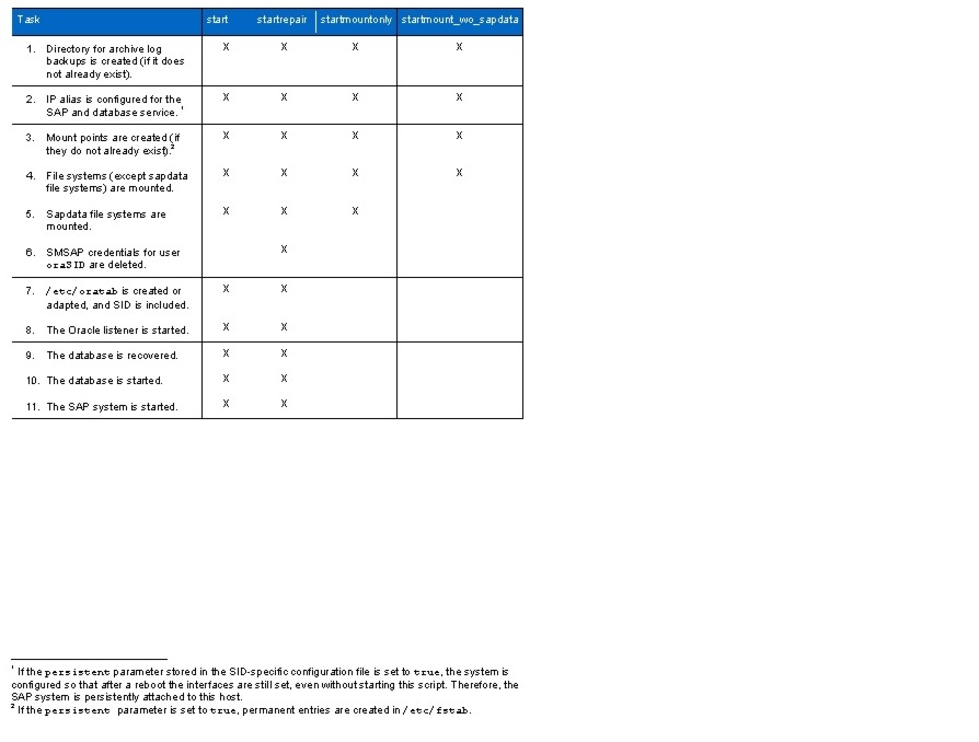
Table 13 Tasks executed with the stop opions

Command line parameters: Tnnn.conf: Full path to the tenant parameter file
Tnnn-SID.conf: Full path to the SID specific parameter file
start or
stop or
startrepair and optional srcDnsDomainAccess=sourcednsdomain or
stoprepair or
startmountonly or
stopmountonly or
starmount_wo_sapdata or
stopmount_wo_sapdata
parameter=value pairs (optional)
Configuration files: Tnnn.conf and Tnnn-SID.conf as command line parameters
Log file: /mnt/data/log/<hostname><script-name><date>.log
Example: ./fp_sap_system.sh /mnt/data/conf/T002.conf /mnt/data/conf/T002-PA1.conf
Executed at host: Tenant-specific services host in the tenant
Executed with user: root
Used for workflow: Repair system, SAP system installation
Description of Example Scripts
backup_repo.sh
Description:
Creates an export of the SMSAP repository database for backup purposes.
Command line parameter: none
Configuration file: none
Log file: /mnt/data/log/<script-name><date>.log
Example: backup_repo.sh
Executed at host: SMSAP repository database host
Executed with user: Oracle
Used for workflow: SMSAP repository backup
create_vfiler.sh
Description:
Creates and configures vFiler units and tenant-specific datasets. This script should be executed only by using the create_vfiler_wrapper.sh script.
•
•
•
•
•
•
•
Command line parameter: <full path to parameter file>
Configuration file: Parameter file through the CLI
Log file: /mnt/data/log/<script-name><date>.log
Example: create_vfiler.sh </mnt/data/conf/parameter.conf>
Executed at host: DFM host
Executed with user: root
Used for workflow: Tenant provisioning, adding vFiler units to a tenant
create_vfiler_wrapper.sh
Description:
Reads the tenant-specific configuration file and calls the script create_vfiler.sh to provision vFiler units for a new tenant or to provision additional vFiler units for an existing tenant.
Command line parameter: <tenant config file>: Full path to tenant config file
Configuration file: tenant configuration file through the CLI
Log file: /mnt/data/log/<hostname><script-name><date>.log
Example: create_vfiler.sh </mnt/data/conf/parameter.conf>
Executed at host: DFM host
Executed with user: root
Used for workflow: Tenant provisioning, adding vFiler units to a tenant
fp_sap_mountpoints.sh
Description:
Creates the necessary subdirectories on the storage volumes that have been provisioned by the script provision_sap_storage.sh, based on the entries in the SID-specific configuration file tnnn-SID.conf. This script temporarily mounts all sapdata exports (those belonging to data and log volumes) and checks whether all folders under the qtree exist. If not, they are created.
In the case of non-SAP volumes such as share, the script checks whether this share is already mounted; if so, it checks whether the folders exist and creates them if required.
Command line parameters: <full path to the tnnn.conf parameter file>
<full path to the tnnn-SID.conf parameter file>
[--testonly] to run in test mode
Configuration file: Parameter files through the CLI
Log file: /mnt/data/log/<script-name><date>.log
Example: fp_sap_mountpoints.sh /mnt/data/conf/t002.conf
/mnt/data/conf/t002-PA6.conf
Executed at host: Tenant-specific services host in the tenant
Executed with user: root
Used for workflow: SAP system provisioning, installation
provisionsapstorage.sh
Description:
Provisions the datastores required to install an SAP system. The layout (volumes, qtrees, and size) is specified in the SID-specific configuration file. For all activities, the script issues dfm commands.
The following steps are taken:
•
•
•
•
•
•
The script can run in a test mode to print out all the required commands.
Command line parameters: <full path to tenant config file tnnn.conf>
<full path to the tnnn-SID.conf config file>
[--testonly] to run in test mode
[parameter=value] : Optional parameter/value pairs
Configuration files: Parameter files through the CLI
Log file: /mnt/data/log/<script-name><date>.log
Example: provisionsapstorage.sh </mnt/data/conf/t002.conf> </mnt/data/conf/t002-PA6.conf>
Executed at host: DFM host
Executed with user: root
Used for workflow: SAP system installation
Description of Workflow Example Scripts
The workflow example scripts are written in Windows PowerShell. The VMware PowerCLI, a PowerShell snap-in, must be installed in the host where the script is running as well as Power Shell itself. NetApp recommends using the Windows system where the VirtualCenter server runs.
DeployNewVm.ps1
Description:
Deploys a new virtual machine by using a VMware template. During the deployment, the script:
•
•
•
•
•
Several parameters, such as the ESX server host name, user names, and passwords must be set in the script.
Command line parameters: VM name
Tenant ID
Template name
Configuration file: none
Log file: .\log\DeployVm_<date>.log
Example: DeployNewVm.ps1 T002-test T002 OSTemplate
Executed at host: vCenter Server
Executed with user: privileged user
Used for workflow: OS provisioning, create repair system
DEPLOYNEWVM_w_RCU.ps1
Description:
This script is the same as DeployNewVM.ps1, but it uses NetApp RCU to clone the VM template.
CreateRepairSystem.ps1
Description:
Example script used to automate the complete process of creating a clone of an existing SAP system in a new tenant. This system can be used as 100% copy for repair purposes that would otherwise require a lengthy backup and restore.
Following are the prerequisites:
•
•
•
This script:
1.
2.
3.
4.
5.
6.
7.
8.
Several parameters, such as the ESX server host name, user names, and passwords, must be set in the script.
Command line parameters: <SID>
<Source Tenant Name>
<Target Tenant Name>
[SMSAP Backup Label]
Configuration file: none
Log file: .\log\CreateRepairSystem_<date>.log
Example: CreateRepairSystem.ps1 PA5 T002 T004 Backup
Executed at host: vCenter Server
Executed with user: privileged user
Used for workflow: Create repair system
CreateRepairSystem_w_RCU.ps1
Description:
This script is the same as CreateRepairSystem.ps1, but it uses NetApp RCU to clone the OS template
DeleteRepairSystem.ps1
Description:
Deletes a clone and the VM created with the previous CreateRepairSystem script.
Prerequisite:
•
The steps are:
1.
2.
3.
Several parameters, such as the ESX server host name, user names, and passwords, must be set in the script.
Command line parameter: <SID>
<Target Tenant Name>
[SMSAP Backup Label]
Configuration file: none
Log file: .\log\DeleteRepairSystem_<date>.log
Example: DeleteRepairSystem.ps1 PA5 T004 Backup
Executed at host: vCenter Server
Executed with user: privileged user
Used for workflow: Delete repair system
Workaround for SMSAP and Virtual Host Names
SMSAP does not handle all operations correctly when virtual host names are used. For some operations, the physical host name of the source or target system is used. The SMSAP GUI stops with an authentication error for this physical host name, but it does not request for the credentials.
The workaround is to set the credentials for the physical host names by using the smsap credential set command. In order to be able to set the credentials, SMSAP must be installed on the host where the SMSAP GUI runs.
After relocating a cloned system to a different host, SMSAP is no longer able to delete the clone because it is trying to connect to the physical host where the clone is no longer running. Deleting the clone can only be done manually, including manual operations in the SMSAP repository database.
SMSAP must be installed at the host where the GUI runs. The GUI is started with the command /opt/NetApp/smsap/bin/smsapgui &.
The parameter saveHostPasswords must be set to true in the SMSAP GUI config file for the user, who runs the GUI. In the following example, the user is smsap-gui.
vi /smsap-gui/.netapp/smsap/3.3.0/gui/state/user.configsaveHostPasswords=trueThe parameter host.credential.persist must be set to true in the SMSAP server config file where the GUI is running.
vi /opt/NetApp/smsap/properties/smsap.confighost.credentials.persist=trueAccess to the physical host name is configured for the user, who runs the GUI by way of the smsap credential set command.
For example, with user smsap-gui:
smsap-gui@fpdfm:~> smsap credential set -host -name
t009-37-lnx.t009.company.corp -username smsap-admin-t009
Enter password for user smsap-admin-t009@t009-37-lnx.t009.company.corp: ************[ INFO] SMSAP-20018: Set password for host credentials: "smsap-admin-t009@t009-37-lnx.t009.demo.flexpod.gopa.de" in user credentials for user: "smsap-gui".smsap-gui@fpdfm:~>After the credentials have been set, the GUI must be restarted.
Note
To avoid authorization errors, the credentials can be set up front for all physical host names where SAP systems can run and for target hosts of clones.
References
•
•
•
•
•
•
•
Appendix
To view the Appendix, click http://www.cisco.com/en/US/docs/unified_computing/ucs/UCS_CVDs/ucs_flexpod_sap_APPENDIX.pdf.
 Feedback