Cisco UCS Infrastructure for Red Hat OpenShift Container Platform Deployment Guide
Available Languages

Cisco UCS Infrastructure for Red Hat OpenShift Container Platform Deployment Guide
Cisco UCS Infrastructure for Red Hat OpenShift Container Platform 3.9 with Container-native Storage Solution
Last Updated: July 24, 2018

About the Cisco Validated Design Program
The Cisco Validated Design (CVD) program consists of systems and solutions designed, tested, and documented to facilitate faster, more reliable, and more predictable customer deployments. For more information, visit:
http://www.cisco.com/go/designzone.
ALL DESIGNS, SPECIFICATIONS, STATEMENTS, INFORMATION, AND RECOMMENDATIONS (COLLECTIVELY, "DESIGNS") IN THIS MANUAL ARE PRESENTED "AS IS," WITH ALL FAULTS. CISCO AND ITS SUPPLIERS DISCLAIM ALL WARRANTIES, INCLUDING, WITHOUT LIMITATION, THE WARRANTY OF MERCHANTABILITY, FITNESS FOR A PARTICULAR PURPOSE AND NONINFRINGEMENT OR ARISING FROM A COURSE OF DEALING, USAGE, OR TRADE PRACTICE. IN NO EVENT SHALL CISCO OR ITS SUPPLIERS BE LIABLE FOR ANY INDIRECT, SPECIAL, CONSEQUENTIAL, OR INCIDENTAL DAMAGES, INCLUDING, WITHOUT LIMITATION, LOST PROFITS OR LOSS OR DAMAGE TO DATA ARISING OUT OF THE USE OR INABILITY TO USE THE DESIGNS, EVEN IF CISCO OR ITS SUPPLIERS HAVE BEEN ADVISED OF THE POSSIBILITY OF SUCH DAMAGES.
THE DESIGNS ARE SUBJECT TO CHANGE WITHOUT NOTICE. USERS ARE SOLELY RESPONSIBLE FOR THEIR APPLICATION OF THE DESIGNS. THE DESIGNS DO NOT CONSTITUTE THE TECHNICAL OR OTHER PROFESSIONAL ADVICE OF CISCO, ITS SUPPLIERS OR PARTNERS. USERS SHOULD CONSULT THEIR OWN TECHNICAL ADVISORS BEFORE IMPLEMENTING THE DESIGNS. RESULTS MAY VARY DEPENDING ON FACTORS NOT TESTED BY CISCO.
CCDE, CCENT, Cisco Eos, Cisco Lumin, Cisco Nexus, Cisco StadiumVision, Cisco TelePresence, Cisco WebEx, the Cisco logo, DCE, and Welcome to the Human Network are trademarks; Changing the Way We Work, Live, Play, and Learn and Cisco Store are service marks; and Access Registrar, Aironet, AsyncOS, Bringing the Meeting To You, Catalyst, CCDA, CCDP, CCIE, CCIP, CCNA, CCNP, CCSP, CCVP, Cisco, the Cisco Certified Internetwork Expert logo, Cisco IOS, Cisco Press, Cisco Systems, Cisco Systems Capital, the Cisco Systems logo, Cisco Unified Computing System (Cisco UCS), Cisco UCS B-Series Blade Servers, Cisco UCS C-Series Rack Servers, Cisco UCS S-Series Storage Servers, Cisco UCS Manager, Cisco UCS Management Software, Cisco Unified Fabric, Cisco Application Centric Infrastructure, Cisco Nexus 9000 Series, Cisco Nexus 7000 Series. Cisco Prime Data Center Network Manager, Cisco NX-OS Software, Cisco MDS Series, Cisco Unity, Collaboration Without Limitation, EtherFast, EtherSwitch, Event Center, Fast Step, Follow Me Browsing, FormShare, GigaDrive, HomeLink, Internet Quotient, IOS, iPhone, iQuick Study, LightStream, Linksys, MediaTone, MeetingPlace, MeetingPlace Chime Sound, MGX, Networkers, Networking Academy, Network Registrar, PCNow, PIX, PowerPanels, ProConnect, ScriptShare, SenderBase, SMARTnet, Spectrum Expert, StackWise, The Fastest Way to Increase Your Internet Quotient, TransPath, WebEx, and the WebEx logo are registered trademarks of Cisco Systems, Inc. and/or its affiliates in the United States and certain other countries.
All other trademarks mentioned in this document or website are the property of their respective owners. The use of the word partner does not imply a partnership relationship between Cisco and any other company. (0809R)
© 2018 Cisco Systems, Inc. All rights reserved.
Table of Contents
Cisco Unified Computing System
Cisco UCS Fabric Interconnects
Cisco UCS 5108 Blade Server Chassis
Cisco UCS C220M5 Rack-Mount Server
Cisco UCS C240M5 Rack-Mount Server
Intel Scalable Processor Family
Red Hat OpenShift Container Platform
Red Hat Enterprise Linux Atomic Host
Red Hat OpenShift Integrated Container Registry
Container-native Storage Solution from Red Hat
Deployment Hardware and Software
Switch Configuration - Cisco Nexus 9396PX
Initial Configuration and Setup
Configuring Network Interfaces
Cisco UCS Manager - Administration
Initial Setup of Cisco Fabric Interconnects
Configuring Ports for Server, Network and Storage Access
Cisco UCS Manager – Setting up NTP Server
Assigning Block of IP addresses for KVM Access
Editing Chassis Discovery Policy
Acknowledging Cisco UCS Chassis
Enabling Uplink Ports to Cisco Nexus 9000 Series Switches
Configuring Port Channels on Uplink Ports to Cisco Nexus 9000 Series Switches
Cisco UCS Configuration – Server
Creating Host Firmware Package Policy
Cisco UCS Configuration – Storage
Creating Service Profile Templates
Creating Service Profile Template for OpenShift Master Nodes
Creating Service Profile Template for Infra Nodes
Creating Service Profile Template for App Nodes
Creating Service Profile Template for App Nodes
Configuring PXE-less Automated OS Installation Infra with UCSM vMedia Policy
Bastion Node – Installation and Configuration
Preparing Bastion Node for vMedia Automated OS Install
Web Server – Installation and Configuration
Service Profile Instantiation and Association
Red Hat Enterprise Linux Atomic Host OS Installation
Provisioning - OpenShift Container Platform
Cloning/Getting OpenShift-UCSM Ansible Playbook code from the GitHub repository
Node Preparation for OpenShift Container Platform Deployment
Setting up Multi-Master HA - Keepalived Deployment
Red Hat OpenShift Container Platform Deployment
Functional Test Cases – OCP/container-native storage
Scaling-up OpenShift Container Platform Cluster Tests
Appendix – I: Additional Components – Metrics and Logging Installation
Appendix – II: Persistent Volume Claim/Application Pod – yml file usage
Application Pod Deployment with PVC
Appendix – III: Disconnected Installation
Appendix – IV: Uninstalling Container-native Storage
Business Challenges
Businesses are increasingly expecting technology to be a centerpiece of every new change. Traditional approaches to leverage technology are too slow in delivering innovation at the pace at which business ecosystems are changing.
To stay competitive, organizations need containerized software applications to meet their unique needs — from customer engagements to new product and services development. With this, businesses are facing challenges around policy management, application portability, agility, resource utilization and so on. In order to keep up with new technologies or stay one step ahead, enterprises will have to overcome the key challenges to accelerate product development, add value and compete better at lower cost.
The need to speed up application development, testing, delivery, and deployment is becoming a necessary business competency. Containers are proving to be the next step forward as they are much lighter to build and deploy in comparison with the methods like omnibus software builds and full Virtual Machine images. Containers are efficient, portable, and agile and is been accepted industry wide for the ease of deployment at scale versus monolithic architecture based applications.
Typically, the container platform is expected to allow developers to focus on their code using their existing tools and familiar workflows including CI/CD. Ideally, developers should not have to worry about (or touch) a Dockerfile and deploy apps from their development environments to any destination including, their laptops, data center and the cloud. It should all be about ease of use and delivering a superior developer experience. Also, it should provide Ops teams enough visibility from app-layer down to container, OS, virtualization and the underlying hardware layer.
Red Hat® OpenShift® Container Platform offers enterprises, a complete control over their Kubernetes environments, whether they are on-premise or in the public cloud, giving them freedom to build and run applications anywhere. Red Hat OpenShift Container Platform 3.9 on Cisco UCS® B- and C- Series severs with Intel’s Intel® Xeon® Scalable processors and storage inspired SATA SSDs optimized for read-intensive workloads is a joint effort by Cisco, Red Hat and Intel to bring in a best-in-class solution to cater to the rapidly growing IT needs.
This CVD is intended to provide an end-to-end solution deployment steps along with the test/ validations performed on the proposed reference architecture. This guide is a step forward to the published design guide, which details the reference architecture design and considerations made. For more information on the design, see: https://www.cisco.com/c/en/us/td/docs/unified_computing/ucs/UCS_CVDs/ucs_openshift_design.html
Introduction
Deployment-centric application platform and DevOps initiatives are driving benefits for organizations in their digital transformation journey. Though still early in maturity, Docker format container packaging and Kubernetes container orchestration are emerging as industry standards for state-of-the-art PaaS solutions.
Cisco, Intel and Red Hat have joined hands to develop a best-in-class, easy-to-deploy PaaS solution on an on-prem, private/ public cloud environments with automated deployments on robust platform such as Cisco UCS and Red Hat OpenShift Container Platform.
Red Hat OpenShift Container Platform provides a set of container-based open source tools that enable digital transformation and accelerates application development while making optimal use of infrastructure. Red Hat OpenShift Container Platform helps organizations use the cloud delivery model and simplify continuous delivery of applications and services in a cloud-native way. Built on proven open source technologies, Red Hat OpenShift Container Platform also provides development teams multiple modernization options to enable smooth transition to microservices architecture and to the cloud for existing traditional applications.
Red Hat OpenShift Container Platform 3.9 is built around a core of application containers powered by Docker, with orchestration and management provided by Kubernetes, on a foundation of Red Hat Enterprise Linux® Atomic Host. It provides many enterprise-ready features, like enhanced security features, multitenancy, simplified application deployment, and continuous integration/ continuous deployment tools. With Cisco UCS M5 servers, provisioning and managing the Red Hat OpenShift Container Platform 3.9 infrastructure becomes practically effortless with stateless computing and single-plane of management, thus giving a resilient solution.
This solution is built on Cisco UCS B-, C-Series M5 servers and Cisco Nexus 9000 Series switches. These servers are powered by the Intel® Xeon® Scalable platform, which provides the foundation for a powerful data center platform that creates an evolutionary leap in agility and scalability. Disruptive by design, this innovative processor sets a new level of platform convergence and capabilities across compute, storage, memory, network, and security.
This solution intends to provide near line rate performance advantage for the container applications through its design principles to run Red Hat OpenShift Container Platform on Cisco UCS Bare Metal servers with Intel best of class CPUs and Solid-State Drives.
This guide provides a step-by-step procedure for deploying Red Hat OpenShift Container Platform 3.9 on Cisco UCS B- and C- Series servers, and also provides a list of feature functional, high-availability and scale tests performed on the enterprise class and dev/ test environments.
Audience
The intended audience for this CVD is system administrators or system architects. Some experience with Cisco UCS, Docker and Red Hat OpenShift technologies might be helpful, but is not required.
Purpose of this Document
This document highlights the benefits of using Cisco UCS M5 servers for Red Hat OpenShift Container Platform 3.9 to efficiently deploy, scale, and manage a production-ready application container environment for enterprise customers. While Cisco UCS infrastructure provides a platform for compute, network and storage requirements, Red Hat OpenShift Container Platform provides a single development platform for new cloud-native applications and transitioning from monoliths to microservices. The goal of this document is to demonstrate the value that Cisco UCS brings to the data center, such as single-point hardware lifecycle management, highly available compute, network, storage infrastructure and the simplicity of deployment of application containers using Red Hat OpenShift Container Platform.
What’s New?
· Automated operating system provisioning.
· Red Hat Ansible® Playbooks for end-to-end deployment of OpenShift Container Platform on UCS infrastructure including Container-native storage solution.
· Automated scale-up/down infrastructure and OpenShift Container Platform components.
· Cisco UCS® M5 servers are based on new Intel® Xeon® Scalable processors with increased core counts, more PCIe lanes, faster memory bandwidth, Optane SSDs and upto 2X higher storage performance.
Solution Summary
This deployment guide provides detailed instructions on preparing, provisioning, deploying, and managing a Red Hat OpenShift Container Platform 3.9 on an on-prem environment with container-native storage solution from Red Hat on Cisco UCS M5 B- and C-Series servers to cater to the stateful application’s persistent storage needs.
Solution Benefits
Some of the key benefits of this solution include:
· Red Hat OpenShift
- Strong, role-based access controls, with integrations to enterprise authentication systems.
- Powerful, web-scale container orchestration and management with Kubernetes.
- Integrated Red Hat Enterprise Linux Atomic Host, optimized for running containers at scale with Security-enhanced Linux (SELinux) enabled for strong isolation.
- Integration with public and private registries.
- Integrated CI/CD tools for secure DevOps practices.
- SDN plugin for container networking in CNI mode.
- Modernize application architectures toward microservices.
- Adopt a consistent application platform for hybrid cloud deployments.
- Support for remote storage volumes.
- Persistent storage for stateful cloud-native containerized applications.
· Cisco UCS
- Reduced data center complexities through Cisco UCS infrastructure with a single management control plane for hardware lifecycle management.
- Easy to deploy and scale the solution.
- Best-in-class performance for container applications running on bare metal servers.
- Superior scalability and high-availability.
- Compute form factor agnostic. Application workload can be distributed across UCS B- and C-Series servers seamlessly.
- Better response with optimal ROI.
- Optimized hardware footprint for production and dev/ test deployments.
This section provides a brief introduction of the various hardware/ software components used in this solution.
Cisco Unified Computing System
The Cisco Unified Computing System is a next-generation solution for blade and rack server computing. The system integrates a low-latency; lossless 10 Gigabit Ethernet unified network fabric with enterprise-class, x86-architecture servers. The system is an integrated, scalable, multi-chassis platform in which all resources participate in a unified management domain. The Cisco Unified Computing System accelerates the delivery of new services simply, reliably, and securely through end-to-end provisioning and migration support for both virtualized and non-virtualized systems. Cisco Unified Computing System (Cisco UCS) fuses access layer networking and servers. This high-performance, next-generation server system provides a data center with a high degree of workload agility and scalability.
Cisco UCS Manager
Cisco Unified Computing System (UCS) Manager provides unified, embedded management for all software and hardware components in the Cisco UCS. Using Single Connect technology, it manages, controls, and administers multiple chassis for thousands of virtual machines. Administrators use the software to manage the entire Cisco Unified Computing System as a single logical entity through an intuitive GUI, a command-line interface (CLI), or an XML API. The Cisco UCS Manager resides on a pair of Cisco UCS 6300 Series Fabric Interconnects using a clustered, active-standby configuration for high-availability.
Cisco UCS Fabric Interconnects
The Fabric interconnects provide a single point for connectivity and management for the entire system. Typically deployed as an active-active pair, the system’s fabric interconnects integrate all components into a single, highly-available management domain controlled by Cisco UCS Manager. The fabric interconnects manage all I/O efficiently and securely at a single point, resulting in deterministic I/O latency regardless of a server or virtual machine’s topological location in the system.
Cisco UCS 5108 Blade Server Chassis
The Cisco UCS 5100 Series Blade Server Chassis is a crucial building block of the Cisco Unified Computing System, delivering a scalable and flexible blade server chassis. The Cisco UCS 5108 Blade Server Chassis is six rack units (6RU) high and can mount in an industry-standard 19-inch rack. A single chassis can house up to eight half-width Cisco UCS B-Series Blade Servers and can accommodate both half-width and full-width blade form factors. Four single-phase, hot-swappable power supplies are accessible from the front of the chassis. These power supplies are 92 percent efficient and can be configured to support non-redundant, N+ 1 redundant and grid-redundant configurations. The rear of the chassis contains eight hot-swappable fans, four power connectors (one per power supply), and two I/O bays for Cisco UCS 2304 Fabric Extenders.
Cisco UCS B200M5 Blade Server
The Cisco UCS B200M5 Blade Server delivers performance, flexibility, and optimization for deployments in data centers, in the cloud, and at remote sites. This enterprise-class server offers market-leading performance, versatility, and density without compromise for workloads including Virtual Desktop Infrastructure (VDI), web infrastructure, distributed databases, converged infrastructure, and enterprise applications such as Oracle and SAP HANA. The B200M5 server can quickly deploy stateless physical and virtual workloads through programmable, easy-to-use Cisco UCS Manager Software and simplified server access through Cisco SingleConnect technology. The Cisco UCS B200M5 server is a half-width blade. Up to eight servers can reside in the 6-Rack-Unit (6RU) Cisco UCS 5108 Blade Server Chassis, offering one of the highest densities of servers per rack unit of blade chassis in the industry. You can configure the B200M5 to meet your local storage requirements without having to buy, power, and cool components that you do not need.
Cisco UCS C220M5 Rack-Mount Server
The Cisco UCS C220M5 Rack Server is among the most versatile general-purpose enterprise infrastructure and application servers in the industry. It is a high-density 2-socket rack server that delivers industry-leading performance and efficiency for a wide range of workloads, including virtualization, collaboration, and bare metal applications. The Cisco UCS C-Series Rack Servers can be deployed as standalone servers or as part of the Cisco Unified Computing System™ (Cisco UCS) to take advantage of Cisco’s standards-based unified computing innovations that help reduce customers’ Total Cost of Ownership (TCO) and increase their business agility. The Cisco UCS C220M5 server extends the capabilities of the Cisco UCS portfolio in a 1-Rack-Unit (1RU) form factor. It incorporates the Intel® Xeon® Scalable processors, supporting up to 20 percent more cores per socket, twice the memory capacity, 20 percent greater storage density, and five times more PCIe NVMe Solid-State Disks (SSDs) compared to the previous generation of servers. These improvements deliver significant performance and efficiency gains that will improve your application performance.
Cisco UCS C240M5 Rack-Mount Server
The Cisco UCS C240M5 Rack Server is a 2-socket, 2-Rack-Unit (2RU) rack server offering industry-leading performance and expandability. It supports a wide range of storage and I/O-intensive infrastructure workloads, from big data and analytics to collaboration. Cisco UCS C-Series Rack Servers can be deployed as standalone servers or as part of a Cisco Unified Computing System™ (Cisco UCS) managed environment to take advantage of Cisco’s standards-based unified computing innovations that help reduce customers’ Total Cost of Ownership (TCO) and increase their business agility.
In response to ever-increasing computing and data-intensive real-time workloads, the enterprise-class Cisco UCS C240M5 server extends the capabilities of the Cisco UCS portfolio in a 2RU form factor. It incorporates the Intel® Xeon® Scalable processors, supporting up to 20 percent more cores per socket, twice the memory capacity, and five times more.
Non-Volatile Memory Express (NVMe) PCI Express (PCIe) Solid-State Disks (SSDs) compared to the previous generation of servers. These improvements deliver significant performance and efficiency gains that will improve your application performance.
Cisco VIC Interface Cards
The Cisco UCS Virtual Interface Card (VIC) 1340 is a 2-port 40-Gbps Ethernet or dual 4 x 10-Gbps Ethernet, Fiber Channel over Ethernet (FCoE) capable modular LAN on motherboard (mLOM) designed exclusively for the M4 generation of Cisco UCS B-Series Blade Servers. All the blade servers for both Controllers and Computes will have MLOM VIC 1340 card. Each blade will have a capacity of 40Gb of network traffic. The underlying network interfaces like will share this MLOM card.
The Cisco UCS Virtual Interface Card 1385 improves flexibility, performance, and bandwidth for Cisco UCS C-Series Rack Servers. It offers dual-port Enhanced Quad Small Form-Factor Pluggable (QSFP+) 40 Gigabit Ethernet and Fibre Channel over Ethernet (FCoE) in a half-height PCI Express (PCIe) adapter. The 1385 card works with Cisco Nexus 40 Gigabit Ethernet (GE) and 10 GE switches for high-performance applications. The Cisco VIC 1385 implements the Cisco Data Center Virtual Machine Fabric Extender (VM-FEX), which unifies virtual and physical networking into a single infrastructure. The extender provides virtual-machine visibility from the physical network and a consistent network operations model for physical and virtual servers.
Cisco Nexus 9000 Switches
The Cisco Nexus 9000 Series delivers proven high performance and density, low latency, and exceptional power efficiency in a broad range of compact form factors. Operating in Cisco NX-OS Software mode or in Application Centric Infrastructure (ACI) mode, these switches are ideal for traditional or fully automated data center deployments.
The Cisco Nexus 9000 Series Switches offer both modular and fixed 10/40/100 Gigabit Ethernet switch configurations with scalability up to 30 Tbps of non-blocking performance with less than five-microsecond latency, 1152 x 10 Gbps or 288 x 40 Gbps non-blocking Layer 2 and Layer 3 Ethernet ports and wire speed VXLAN gateway, bridging, and routing.
Intel Scalable Processor Family
Intel® Xeon® Scalable processors provide a new foundation for secure, agile, multi-cloud data centers. This platform provides businesses with breakthrough performance to handle system demands ranging from entry-level cloud servers to compute-hungry tasks including real-time analytics, virtualized infrastructure, and high-performance computing. This processor family includes technologies for accelerating and securing specific workloads. The integrated Intel® Omni-Path Architecture (Intel® OPA) Host Fabric Interface provides End-to-end high-bandwidth, low-latency fabric that optimizes performance and eases deployment of HPC clusters by eliminating the need for a discrete host fabric interface card, and is integrated in the CPU package.
Intel® SSD DC S4500 Series
Intel® SSD DC S4500 Series is storage inspired SATA SSD optimized for read-intensive workloads. Based on TLC Intel® 3D NAND Technology, these larger capacity SSDs enable data centers to increase data stored per rack unit. Intel® SSD DC S4500 Series is built for compatibility in legacy infrastructures so it enables easy storage upgrades that minimize the costs associated with modernizing data center. This 2.5” 7mm form factor offers wide range of capacity from 240 GB up to 3.8 TB.
Red Hat OpenShift Container Platform
OpenShift Container Platform is Red Hat’s container application platform that brings together Docker and Kubernetes and provides an API to manage these services. OpenShift Container Platform allows you to create and manage containers. Containers are standalone processes that run within their own environment, independent of operating system and the underlying infrastructure. OpenShift helps developing, deploying, and managing container-based applications. It provides a self-service platform to create, modify, and deploy applications on demand, thus enabling faster development and release life cycles. OpenShift Container Platform has a microservices-based architecture of smaller, decoupled units that work together. It runs on top of a Kubernetes cluster, with data about the objects stored in etcd, a reliable clustered key-value store.
Kubernetes Infrastructure
Within OpenShift Container Platform, Kubernetes manages containerized applications across a set of Docker runtime hosts and provides mechanisms for deployment, maintenance, and application-scaling. The Docker service packages, instantiates, and runs containerized applications.
A Kubernetes cluster consists of one or more masters and a set of nodes. This solution design includes HA functionality at the hardware as well as the software stack. Kubernetes cluster is designed to run in HA mode with 3 master nodes and 2 Infra nodes to ensure that the cluster has no single point of failure.
Red Hat Enterprise Linux Atomic Host
Red Hat Enterprise Linux Atomic Host is a lightweight variant of the Red Hat Enterprise Linux operating system designed to exclusively run Linux containers. By combining the modular capabilities of Linux containers and Red Hat Enterprise Linux, containers can be more securely and effectively deployed and managed across public, private, and hybrid cloud infrastructures.
Red Hat OpenShift Integrated Container Registry
OpenShift Container Platform provides an integrated container registry called OpenShift Container Registry (OCR) that adds the ability to automatically provision new image repositories on demand. This provides users with a built-in location for their application builds to push the resulting images. Whenever a new image is pushed to OCR, the registry notifies OpenShift Container Platform about the new image, passing along all the information about it, such as the namespace, name, and image metadata. Different pieces of OpenShift Container Platform react to new images, creating new builds and deployments.
Container-native Storage Solution from Red Hat
Container-native storage solution from Red Hat makes OpenShift Container Platform a fully hyperconverged infrastructure where storage containers co-reside with the compute containers. Storage plane is based on containerized Red Hat Gluster® Storage services, which controls storage devices on every storage server. Heketi is a part of the container-native storage architecture and controls all of the nodes that are members of storage cluster. Heketi also provides an API through which storage space for containers can be easily requested. While Heketi provides an endpoint for storage cluster, the object that makes calls to its API from OpenShift clients is called a Storage Class. It is a Kubernetes and OpenShift object that describes the type of storage available for the cluster and can dynamically send storage requests when a persistent volume claim is generated.
Container-native storage for OpenShift Container Platform is built around three key technologies:
· OpenShift provides the Platform-as-a-Service (PaaS) infrastructure based on Kubernetes container management. Basic OpenShift architecture is built around multiple master systems where each system contains a set of nodes.
· Red Hat Gluster Storage provides the containerized distributed storage based on Red Hat Gluster Storage container. Each Red Hat Gluster Storage volume is composed of a collection of bricks, where each brick is the combination of a node and an export directory.
· Heketi provides the Red Hat Gluster Storage volume life cycle management. It creates the Red Hat Gluster Storage volumes dynamically and supports multiple Red Hat Gluster Storage clusters.
Docker
Red Hat OpenShift Container Platform uses Docker runtime engine for containers.
Kubernetes
Red Hat OpenShift Container Platform is a complete container application platform that natively integrates technologies like Docker and Kubernetes - a powerful container cluster management and orchestration system.
Etcd
Etcd is a key-value store used in OpenShift Container Platform cluster. Etcd data store provides complete cluster and endpoint states to the OpenShift API servers. Etcd data store furnishes information to API servers about node status, network configurations, secrets etc.
Open vSwitch
Open vSwitch is an open-source implementation of a distributed virtual multilayer switch. It is designed to enable effective network automation through programmatic extensions, while supporting standard management interfaces and protocols such as 802.1ag, SPAN, LACP and NetFlow. Open vSwitch provides software-defined networking (SDN)-specific functions in the OpenShift Container Platform environment.
HAProxy
HAProxy is open source software that provides a high availability load balancer and proxy server for TCP and HTTP-based applications that spreads requests across multiple servers. In this solution, HAProxy provides routing and load-balancing functions for Red Hat OpenShift applications. Other instance of HAProxy acts as an ingress router for all applications deployed in Red Hat OpenShift cluster. Both instances are replicated to every infrastructure node and managed by additional components (keepalived, OpenShift services) to provide redundancy and high availability.
Keepalived
Keepalived is routing software which provides simple and robust facilities for load balancing and high-availability to Linux based infrastructure. In this solution, keepalived is used to provide virtual IP management for HAProxy instances to ensure highly available OpenShift Container Platform cluster. Keepalived is deployed into infrastructure nodes as they also act as HAProxy load balancers. In case of a failure of one infrastructure node Keepalived automatically moves Virtual IPs to second node that acts as a backup. With Keepalived Red Hat OpenShift infrastructure becomes highly available and resistant to failures.
Red Hat Ansible Automation
Red Hat Ansible Automation is a powerful IT automation tool. It is capable of provisioning numerous types of resources and deploying applications. It can configure and manage devices and operating system components. Due to the simplicity, extensibility, and portability, this OpenShift solution is based largely on Ansible Playbooks.
Ansible is mainly used for installation and management of the Red Hat OpenShift Container Platform deployment.
For in-depth description of each hardware and software components, refer solution design guide at: https://www.cisco.com/c/en/us/td/docs/unified_computing/ucs/UCS_CVDs/ucs_openshift_design.html
This section provides an overview of the hardware and software components used in this solution, as well as the design factors to be considered in order to make the system work as a single, highly available solution. In addition to this, the section also describes in detail, end-to-end deployment steps for the solution.
Architecture
Red Hat OpenShift Container Platform is managed by the Kubernetes container orchestrator, which manages containerized applications across a cluster of systems running the Docker container runtime. The physical configuration of Red Hat OpenShift Container Platform is based on the Kubernetes cluster architecture. OpenShift is a layered system designed to expose underlying Docker-formatted container image and Kubernetes concepts as accurately as possible, with a focus on easy composition of applications by a developer. For example, install Ruby, push code, and add MySQL. The concept of an application as a separate object is removed in favor of more flexible composition of "services", allowing two web containers to reuse a database or expose a database directly to the edge of the network.
Figure 1 Red Hat OpenShift Container Platform Architecture Overview

This Red Hat OpenShift RA contains five types of nodes: bastion, master, infrastructure, storage, and application.
· Bastion Node:
This is a dedicated node that serves as the main deployment and management server for the Red Hat OpenShift cluster. It is used as the logon node for the cluster administrators to perform the system deployment and management operations, such as running the Ansible OpenShift deployment Playbooks and performing scale-out operations. Also, Bastion node runs DNS services for the OpenShift Cluster nodes. The bastion node runs Red Hat Enterprise Linux 7.5.
· OpenShift Master Nodes:
The OpenShift Container Platform master is a server that performs control functions for the whole cluster environment. It is responsible for the creation, scheduling, and management of all objects specific to Red Hat OpenShift. It includes API, controller manager, and scheduler capabilities in one OpenShift binary. It is also a common practice to install an etcd key-value store on OpenShift masters to achieve a low-latency link between etcd and OpenShift masters. It is recommended that you run both Red Hat OpenShift masters and etcd in highly available environments. This can be achieved by running multiple OpenShift masters in conjunction with an external active-passive load balancer and the clustering functions of etcd. The OpenShift master node runs Red Hat Enterprise Linux Atomic Host 7.5.
· OpenShift Infrastructure Nodes:
The OpenShift infrastructure node runs infrastructure specific services: Docker Registry*, HAProxy router, and Heketi. Docker Registry stores application images in the form of containers. The HAProxy router provides routing functions for Red Hat OpenShift applications. It currently supports HTTP(S) traffic and TLS-enabled traffic via Server Name Indication (SNI). Heketi provides management API for configuring GlusterFS persistent storage. Additional applications and services can be deployed on OpenShift infrastructure nodes. The OpenShift infrastructure node runs Red Hat Enterprise Linux Atomic Host 7.5.
· OpenShift Application Nodes:
The OpenShift application nodes run containerized applications created and deployed by developers. An OpenShift application node contains the OpenShift node components combined into a single binary, which can be used by OpenShift masters to schedule and control containers. A Red Hat OpenShift application node runs Red Hat Enterprise Linux Atomic Host 7.5.
· OpenShift Storage Nodes:
The OpenShift storage nodes run containerized GlusterFS services which configure persistent volumes for application containers that require data persistence. Persistent volumes may be created manually by a cluster administrator or automatically by storage class objects. An OpenShift storage node is also capable of running containerized applications. A Red Hat OpenShift storage node runs Red Hat Enterprise Linux Atomic Host 7.5.
Below table shows functions and roles, each class of node in this solution reference design of OpenShift Container Platform:
Table 1 Type of nodes in OpenShift Container Platform cluster and their roles
| Node | Roles |
| Bastion Node | - System deployment and Management Operations - Runs DNS services for the OpenShift Container Platform cluster - Provides IP masquerading services to the internal cluster nodes |
| Master Nodes | - Kubernetes services - Etcd data store - Controller Manager & Scheduler - API services |
| Infrastructure Nodes | - Container Registry - HA Proxy - Heketi - KeepAlived |
| Application Nodes | - Application Containers PODs - Docker Runtime |
| Storage Nodes | - Red Hat Gluster Storage - Container-native storage services - Storage nodes are labeled `compute`, so workload scheduling is enabled by default |
![]() Etcd data store which is KV pair database used by Kubernetes, is co-hosted on master nodes running other services like Controller Manager, API and Scheduling.
Etcd data store which is KV pair database used by Kubernetes, is co-hosted on master nodes running other services like Controller Manager, API and Scheduling.
Topology
Physical Topology Reference Architecture Production Use Case
The Physical Topology for Architecture – I: High-End Production use case, includes 9x Cisco UCS B200M5s, 1xCisco UCS C220M5 and 3x Cisco UCS C240M5 blade and rack servers, UCS Fabric Interconnects 6332-16UP and Cisco Nexus 9396PX switches. All the nodes are provisioned with SSDs as storage devices including container-native storage nodes for persistent storage provisioning.
Figure 2 Reference Architecture – Production Use Case

Physical Topology Reference Architecture Dev/ Test Use Case
The Physical Topology for Architecture – II: Starter Dev/ Test use case includes 5xCisco UCS C240M5 and 4xCisco UCS C220M5 rack servers, UCS Fabric Interconnects 6332-16UP and Cisco Nexus 9396PX switches. All the nodes are provisioned with HDDs as storage devices including storage nodes for container-native storage. App nodes are co-located with 2-node Infra as well 3-node storage cluster on Cisco UCS C240M5 servers.
Figure 3 Reference Architecture – Dev/ Test Use Case

Logical Topology Reference Architecture Production Use Case
The cluster node roles and various services they provide are shown in the diagram below.
Figure 4 Logical Topology Reference Architecture Production Use Case

Logical Topology Reference Architecture Dev/ Test Use Case
In this architecture option, 2-nodes are dedicated for Infra services and 3-nodes for container-native storage services. In this architecture, Application nodes are co-hosted on 2 of the Infra nodes and container-native storage services are co-hosted on the rest of the 3 Application nodes. Master and Bastion nodes remain dedicated for the services and roles they perform in the cluster.
Figure 5 Logical Reference Architecture for Dev/ Test Use Case

Physical Network Connectivity
Following figures illustrates cabling details for the two architectures.
Figure 6 Production Use Case

Figure 7 Dev/ Test Use Case

Network Addresses
Following tables list out network subnets, VLANs and addresses used in the solution. These are examples and are not mandated to be used as is, for other deployments. Consumers of this solution are free to use their own address/VLANs/subnets based on their environment, as long as they fit into overall scheme.
Architecture - I: Production Use Case (high performance)
Table 2 Network Subnets
| Network | VLAN ID | Interface | Purpose |
| 10.65.121.0/24 | 602 | Mgmt0/Bond0 | Management Network with External Connectivity |
| 10.65.122.0/24 | 603 | eno6 | External Network |
| 100.100.100.0/24 | 1001 | eno5 | Internal Cluster Network - Host |
| 172.25.0.0/16 | 1001 | eno5 | Internal Subnet used by OpenShift Container Platform SDN plugin for service provisioning |
| 172.28.0.0/14 | 1001 | eno5 | Internal Cluster Network – POD |
Table 3 Cluster Node Addresses
| Host | Interface 1 | Interface 2 | Purpose |
| Bastion Node | Bond0/10.65.121.50 | Bond1001/100.100.100.10 | DNS services, vMedia Policy Repo Host |
| OCP-Infra-1 | eno5/100.100.100.51 | eno6/10.65.122.61 | Registry Services, HA-Proxy, Keepalived, OpenShift Router, Logging and Metrices |
| OCP-Infra-2 | eno5/100.100.100.52 | eno6/10.65.122.62 | Registry Services, HA-Proxy, Keepalived, OpenShift Router, Logging and Metrices |
| OCP-Mstr-1 | eno5/100.100.100.53 | - | Kubernetes services, etcd data store, API services, Controller and Scheduling services |
| OCP-Mstr-2 | eno5/100.100.100.54 | - | Kubernetes services, etcd data store, API services, Controller and Scheduling services |
| OCP-Mstr-3 | eno5/100.100.100.56 | - | Kubernetes services, etcd data store, API services, Controller and Scheduling services |
| OCP-App-1 | eno5/100.100.100.57 | - | Container Runtime, Application Container PODs |
| OCP-App-2 | eno5/100.100.100.58 | - | Container Runtime, Application Container PODs |
| OCP-App-3 | eno5/100.100.100.59 | - | Container Runtime, Application Container PODs |
| OCP-App-4 | eno5/100.100.100.60 | - | Container Runtime, Application Container PODs |
| OCP-Strg-1 | eno5/100.100.100.61 | - | Red Hat Gluster Storage, Container-native storage Services (CNS) and Storage Backend |
| OCP-Strg-2 | eno5/100.100.100.62 | - | Red Hat Gluster Storage, container-native storage Services (CNS) and Storage Backend |
| OCP-Strg-3 | eno5/100.100.100.62 | - | Red Hat Gluster Storage, Container-native storage Services (CNS) and Storage Backend |
Architecture - II: Dev/ Test Use Case
Table 4 Network Subnets
| Network | VLAN ID | Interface | Purpose |
| 10.65.122.0/24 | 603 | Mgmt0/Bond0 | Management Network with External Connectivity |
| 10.65.121.0/24 | 602 | eno6 | External Network |
| 201.201.201.0/24 | 2001 | eno5 | Internal Cluster Network - Host |
| 172.25.0.0/16 | 2001 | eno5 | Internal Subnet used by OpenShift Container Platform SDN plugin for service provisioning |
| 172.28.0.0/14 | 2001 | eno5 | Internal Cluster Network – POD |
Table 5 Cluster Node Addresses
| Host | Interface 1 | Interface 2 | Purpose |
| Bastion Node | Bond0/10.65.122.99 | Bond1001/201.201.201.10 | OpenShift DNS services, vMedia Policy Repo Host |
| OCP-Infra-1 | eno5/201.201.201.51 | eno6/10.65.121.121 | Registry Services, HA-Proxy, Keepalived, OpenShift Router, Logging and Metrices, Container Runtime, Application Container PODs |
| OCP-Infra-2 | eno5/201.201.201.52 | eno6/10.65.121.122 | Registry Services, HA-Proxy, Keepalived, OpenShift Router, Logging and Metrices, Container Runtime, Application Container PODs |
| OCP-Mstr-1 | eno5/201.201.201.53 | - | Kubernetes services, etcd data store, API services, Controller and Scheduling services |
| OCP-Mstr-2 | eno5/201.201.201.54 | - | Kubernetes services, etcd data store, API services, Controller and Scheduling services |
| OCP-Mstr-3 | eno5/201.201.201.56 | - | Kubernetes services, etcd data store, API services, Controller and Scheduling services |
| OCP-App-1 | eno5/201.201.201.57 | - | Container Runtime, Application Container PODs, Red Hat Gluster Storage, Container-native storage services(CNS) and Storage Backend |
| OCP-App-2 | eno5/201.201.201.58 | - | Container Runtime, Application Container PODs, Red Hat Gluster Storage, Container-native storage services(CNS) and Storage Backend |
| OCP-App-3 | eno5/201.201.201.59 | - | Container Runtime, Application Container PODs, Red Hat Gluster Storage, Container-native storage services(CNS) and Storage Backend |
Logical Network Connectivity
This section provides details on how Cisco VIC enables application containers to use dedicated I/O path for network access in a secured environment with multi-tenancy. With Cisco VIC, containers get a dedicated physical path to a classic L2 VLAN topology with better line rate efficiency. To further enhance the value of Cisco UCS by optimizing the infrastructure utilization, the traffic paths were configured to segregate all management/control traffic through fabric interconnect A, and container data traffic through fabric interconnect B.
Figure 8 Logical Network Diagram

Physical Infrastructure
This section describes various hardware and software components used in the RA and this deployment guide. The following infrastructure components are needed for the two architectural options under the solution.
Table 6 Architecture - I: Production Use Case (high performance)
| Component | Model | Quantity | Description |
| App nodes | Cisco UCS B200M5 | 4 | CPU – 2 x 6130@2.1GHz,16 Cores each Memory – 24 x 16GB 2666 DIMM – total of 384G SSDs – 2x960GB 6G SATA -EV (Intel S4500 Enterprise Value) Network Card – 1x1340 VIC + 1xPort Expander for 40Gig network I/O Raid Controller – Cisco MRAID 12 G SAS Controller |
| Master nodes | Cisco UCS B200M5 | 3 | CPU – 2 x 4114@2.2GHz,10Cores each Memory – 12 x 16GB 2400 DIMM – total of 192G SSDs – 2x240GB 6G SATA -EV Network Card – 1x1340 VIC + 1xPort Expander for 40Gig network I/O Raid Controller – Cisco MRAID 12 G SAS Controller |
| Infra nodes | Cisco UCS B200M5 | 2 | CPU – 2 x 4114@2.2GHz,10Cores each Memory – 12 x 16GB 2400 DIMM – total of 192G SSDs – 2x240GB 6G SATA -EV Network Card – 1x1340 VIC + 1xPort Expander for 40Gig network I/O Raid Controller – Cisco MRAID 12 G SAS Controller |
| Bastion node | Cisco UCS C220M5 | 1 | CPU – 2 x 4114@2.2GHz,10Cores each Memory – 12 x 16GB 2400 DIMM – total of 192G HDDs – 2x300GB12GSAS10KSFF Network Card – 1x1385 VIC RAID Controller - Cisco MRAID 12 G SAS Controller |
| Storage nodes | Cisco UCS C240M5SX | 3 | CPU – 2 x 6130@2.1GHz,16 Cores each Memory – 12 x 16GB 2666 DIMM – total of 192G SSDs – 2x240GB 6G SATA -EV SSDs - 20x3.8TB SATA (Intel S4500 Enterprise Value) Network Card – 1x1385 VIC Raid Controller – Cisco MRAID 12 G SAS Controller |
| Chassis | Cisco UCS 5108 | 2 |
|
| IO Modules | Cisco IOM 2304 | 4 |
|
| Fabric Interconnects | Cisco UCS 6332-16UP | 2 |
|
| Switches | Cisco Nexus 9396PX | 2 |
|
Table 7 Architecture - II: Dev/ Test Use Case
| Component | Model | Quantity | Description |
| Application+Storage nodes co-located | Cisco UCS C240M5SX | 3 | CPU – 2 x 4114@2.2GHz,10Cores each Memory – 12 x 16GB 2400 DIMM – total of 192G HDDs – 2x300GB 12GSAS 10KSFF (Internal Boot Drives) HDDs – 20x1.2TB12GSAS10KSFF Network Card – 1x1385 VIC Raid Controller – Cisco MRAID 12 G SAS Controller |
| Application+Infra | Cisco UCS C240M5SX | 2 | CPU – 2 x 4114@2.2GHz,10Cores each Memory – 12 x 16GB 2400 DIMM – total of 192G HDDs – 2x300GB 12GSAS 10KSFF (Internal Boot Drives) Network Card – 1x1385 VIC Raid Controller – Cisco MRAID 12 G SAS Controller |
| Master nodes | Cisco UCS C220M5 | 3 | CPU – 2 x 4114@2.2GHz,10Cores each Memory – 12 x 16GB 2400 DIMM – total of 192G HDDs – 2x300GB 12GSAS 10KSFF Network Card – 1x1385 VIC Raid Controller – Cisco MRAID 12 G SAS Controller |
| Bastion node | Cisco UCS C220M5 | 1 | CPU – 2 x 4114@2.2GHz,10Cores each Memory – 12 x 16GB 2400 DIMM – total of 192G HDDs – 2x300GB 12GSAS 10KSFF Network Card – 1x1385 VIC RAID Controller - Cisco MRAID 12 G SAS Controller |
| Fabric Interconnects | Cisco UCS 6332-16UP | 2 |
|
| Switches | Cisco UCS Nexus 9396PX | 2 |
|
Table 8 Software Components
| Component | Version |
| Cisco UCS Manager | 3.2.(3d) |
| Red Hat Enterprise Linux | 7.5 |
| Red Hat Enterprise Linux Atomic Host | 7.5 |
| Red Hat OpenShift Container Platform | 3.9 |
| Container-native storage solution from Red Hat | 3.9 |
| Kubernetes | 1.9.1 |
| Docker | 1.13.1 |
| Red Hat Ansible Engine | 2.4.4 |
| Etcd | 3.2.18 |
| Open vSwitch | 2.7.3 |
| HAProxy - Router | 1.8.1 |
| HAProxy – Load Balancer | 1.5.18 |
| Keepalived | 1.3.5 |
| Red Hat Gluster Storage | 3.3.0 |
| GlusterFS | 3.8.4 |
| Heketi | 6.0.0 |
Switch Configuration - Cisco Nexus 9396PX
Initial Configuration and Setup
This section outlines the initial configuration necessary for bringing up a new Cisco Nexus 9000.
Cisco Nexus A
To set up the initial configuration for the first Cisco Nexus switch complete the following steps:
1. Connect to the serial or console port of the switch
Enter the configuration method: console
Abort Auto Provisioning and continue with normal setup? (yes/no[n]: y
---- System Admin Account Setup ----
Do you want to enforce secure password standard (yes/no[y] :
Enter the password for "admin":
Confirm the password for "admin":
---- Basic System Configuration Dialog VDC: 1 ----
This setup utility will guide you through the basic configuration of the system. Setup configures only enough connectivity for management of the system.
Please register Cisco Nexus9000 Family devices promptly with your supplier. Failure to register may affect response times for initial service calls. Nexus9000 devices must be registered to receive entitled support services.
Press Enter at anytime to skip a dialog. Use ctrl-c at anytime to skip the remaining dialogs.
Would you like to enter the basic configuration dialog (yes/no): y
Create another login account (yes/no) [n]: n
Configure read-only SNMP community string (yes/no) [n]:
Configure read-write SNMP community string (yes/no) [n]:
Enter the switch name: OCP-N9K-A
Continue with Out-of-band (mgmt0) management configuration? (yes/no) [y]:
Mgmt0 IPv4 address: xxx.xxx.xxx.xxx
Mgmt0 IPv4 netmask: 255.255.255.0
Configure the default gateway? (yes/no) [y]:
IPv4 address of the default gateway: xxx.xxx.xxx.xxx
Configure advanced IP options? (yes/no) [n]:
Enable the telnet service? (yes/no) [n]:
Enable the ssh service? (yes/no) [y]:
Type of ssh key you would like to generate (dsa/rsa) [rsa]:
Number of rsa key bits <1024-2048> [1024]: 2048
Configure the ntp server? (yes/no) [n]: y
NTP server IPv4 address: yy.yy.yy.yy
Configure default interface layer (L3/L2) [L2]:
Configure default switchport interface state (shut/noshut) [noshut]:
Configure CoPP system profile (strict/moderate/lenient/dense/skip) [strict]:
2. Review the settings printed to the console. If they are correct, answer yes to apply and save the configuration
3. Wait for the login prompt to make sure that the configuration has been saved prior to proceeding.
Cisco Nexus B
To set up the initial configuration for the second Cisco Nexus switch complete the following steps:
1. Connect to the serial or console port of the switch
2. The Cisco Nexus B switch should present a configuration dialog identical to that of Cisco Nexus A shown above. Provide the configuration parameters specific to Cisco Nexus B for the following configuration variables. All other parameters should be identical to that of Cisco Nexus A.
Admin password
Nexus B Hostname: OCP-N9K-B
Nexus B mgmt0 IP address: xxx.xxx.xxx.xxx
Nexus B mgmt0 Netmask: 255.255.255.0
Nexus B mgmt0 Default Gateway: xxx.xxx.xxx.xxx
Feature Enablement
The following commands enable the IP switching feature and set default spanning tree behaviors:
1. On each Nexus 9000, enter the configuration mode:
config terminal
2. Use the following commands to enable the necessary features:
feature udld
feature lacp
feature vpc
feature interface-vlan
3. Configure the spanning tree and save the running configuration to start-up:
spanning-tree port type network default
spanning-tree port type edge bpduguard default
spanning-tree port type edge bpdufilter default
copy run start
VLAN Creation
To create the necessary virtual local area networks (VLANs), complete the following step on both switches:
From the configuration mode, run the following commands:
vlan 603
name vlan603
vlan 602
name vlan602
Configuring VPC
Configuring VPC Domain
Cisco Nexus A
To configure virtual port channels (vPCs) for switch A, complete the following steps:
1. From the global configuration mode, create a new vPC domain:
vpc domain 10
2. Make Cisco Nexus A the primary vPC peer by defining a low priority value:
role priority 10
3. Use the management interfaces on the supervisors of the Cisco Nexus switches to establish a keepalive line
peer-keepalive destination xx.xx.xx.xx source yy.yy.yy.yy
4. Enable following features for this vPC domain:
peer-switch
delay restore 150
peer-gateway
ip arp synchronize
auto-recovery
5. Save the configuration.
copy run start
Cisco Nexus B
To configure vPCs for switch B, complete the following steps:
6. From the global configuration mode, create a new vPC domain:
vpc domain 10
7. Make Cisco Nexus A the primary vPC peer by defining a higher priority value on this switch:
role priority 20
8. Use the management interfaces on the supervisors of the Cisco Nexus switches to establish a keepalive link:
peer-keepalive destination yy.yy.yy.yy source xx.xx.xx.xx
9. Enable following features for this vPC domain:
peer-switch
delay restore 150
peer-gateway
ip arp synchronize
auto-recovery
10. Save the configuration:
copy run start
Configuring Network Interfaces for VPC Peer Links
Cisco Nexus A
1. Define a port description for the interfaces connecting to VPC Peer OCP-N9K-B.
interface Eth1/9
description VPC Peer OCP-N9K-B:e1/10
interface Eth1/10
description VPC Peer OCP-N9K-B:e1/9
2. Apply a port channel to both VPC Peer links and bring up the interfaces.
interface Eth1/9,Eth1/10
channel-group 11 mode active
no shutdown
3. Enable UDLD on both interfaces to detect unidirectional links.
udld enable
4. Define a description for the port-channel connecting to OCP-N9K-B.
interface port-channel 11
description vPC peer-link
5. Make the port-channel a switchport, and configure a trunk to allow in-band management, VM traffic, and the native VLAN.
switchport
switchport mode trunk
switchport trunk native vlan 602-603
spanning-tree port type network
6. Make this port-channel the VPC peer link and bring it up.
vpc peer-link
no shutdown
copy run start
Cisco Nexus B
7. Define a port description for the interfaces connecting to VPC Peer OCP-N9K-A.
interface Eth1/9
description VPC Peer OCP-N9K-A:e1/10
interface Eth1/10
description VPC Peer OCP-N9K-A:e1/9
8. Apply a port channel to both VPC Peer links and bring up the interfaces.
interface Eth1/9,Eth1/10
channel-group 11 mode active
no shutdown
9. Enable UDLD on both interfaces to detect unidirectional links.
udld enable
10. Define a description for the port-channel connecting to OCP-N9K-A.
interface port-channel 11
description vPC peer-link
11. Make the port-channel a switchport, and configure a trunk to allow in-band management, VM traffic, and the native VLAN.
switchport
switchport mode trunk
switchport trunk native vlan 602-603
spanning-tree port type network
12. Make this port-channel the VPC peer link and bring it up.
vpc peer-link
no shutdown
copy run start
Configuring Network Interfaces
Cisco Nexus A
1. Define a description for the port-channel connecting to OCP-FI-A.
interface port-channel 12
description OCP-FI-A
2. Make the port-channel a switchport, and configure a trunk to allow in-band management, VM traffic, and the native VLANs.
switchport mode trunk
switchport trunk native vlan 602-603
3. Make the port channel and associated interfaces spanning tree edge ports.
spanning-tree port type edge trunk
spanning-tree guard root
no lacp graceful-convergence
4. Make this a VPC port-channel and bring it up.
vpc 12
no shutdown
5. Define a port description for the interface connecting to OCP-FI-A.
interface Eth2/1
6. Apply it to a port channel and bring up the interface.
channel-group 12 mode active
no shutdown
7. Enable UDLD to detect unidirectional links.
udld enable
8. Define a description for the port-channel connecting to OCP-FI-B.
interface port-channel
description OCP-FI-B
9. Make the port-channel a switchport, and configure a trunk to allow in-band management, VM traffic VLANs and the native VLAN.
switchport mode trunk
switchport trunk native vlan 603
10. Make the port channel and associated interfaces spanning tree edge ports.
spanning-tree port type edge trunk
spanning-tree guard root
no lacp graceful-convergence
11. Make this a VPC port-channel and bring it up.
vpc 13
no shutdown
12. Define a port description for the interface connecting to OCP-FI-B.
interface Eth2/2
13. Apply it to a port channel and bring up the interface.
channel-group 13 mode active
no shutdown
14. Enable UDLD to detect unidirectional links.
udld enable
copy run start
Cisco Nexus B
1. Define a description for the port-channel connecting to OCP-FI-B.
interface port-channel 12
description OCP-FI-B
2. Make the port-channel a switchport, and configure a trunk to allow in-band management, VM traffic, and the native VLANs.
switchport mode trunk
switchport trunk native vlan 603
3. Make the port channel and associated interfaces spanning tree edge ports.
spanning-tree port type edge trunk
spanning-tree guard root
no lacp graceful-convergence
4. Make this a VPC port-channel and bring it up.
vpc 12
no shutdown
5. Define a port description for the interface connecting to OCP-FI-B.
interface Eth2/1
6. Apply it to a port channel and bring up the interface.
channel-group 12 mode active
no shutdown
7. Enable UDLD to detect unidirectional links.
udld enable
8. Define a description for the port-channel connecting to OCP-FI-A.
interface port-channel 13
description OCP-FI-A
9. Make the port-channel a switchport, and configure a trunk to allow in-band management, and VM traffic VLANs and the native VLAN.
switchport mode trunk
switchport trunk native vlan 603
10. Make the port channel and associated interfaces spanning tree edge ports.
spanning-tree port type edge trunk
spanning-tree guard root
no lacp graceful-convergence
11. Make this a VPC port-channel and bring it up.
vpc 13
no shutdown
12. Define a port description for the interface connecting to OCP-N9K-A.
interface Eth2/2
13. Apply it to a port channel and bring up the interface.
channel-group 13 mode active
no shutdown
14. Enable UDLD to detect unidirectional links.
udld enable
copy run start
Cisco UCS Manager - Administration
Initial Setup of Cisco Fabric Interconnects
A pair of Cisco UCS 6332-16UP Fabric Interconnects is used in this design. The minimum configuration required for bringing up the FIs and the embedded Cisco UCS Manager (UCSM) is outlined below. All configurations after this will be done using Cisco UCS Manager.
Cisco UCS 6332-16UP FI – Primary (FI-A)
1. Connect to the console port of the primary Cisco UCS FI.
Enter the configuration method: console
Enter the setup mode; setup newly or restore from backup.(setup/restore)? Setup You have chosen to setup a new fabric interconnect? Continue? (y/n): y
Enforce strong passwords? (y/n) [y]: y
Enter the password for "admin": <Enter Password>
Enter the same password for "admin": <Enter Password>
Is this fabric interconnect part of a cluster (select 'no' for standalone)? (yes/no) [n]: y
Which switch fabric (A|B): A
Enter the system name: OCP-FI
Physical switch Mgmt0 IPv4 address: xx.xx.xx.xx
Physical switch Mgmt0 IPv4 netmask: 255.255.255.0
IPv4 address of the default gateway: yy.yy.yy.yy
Cluster IPv4 address: xx.xx.xx.xx
Configure DNS Server IPv4 address? (yes/no) [no]: y
DNS IPv4 address: yy.yy.yy.yy
Configure the default domain name? y
Default domain name: <domain name>
Join centralized management environment (UCS Central)? (yes/no) [n]: <Enter>
2. Review the settings printed to the console. If they are correct, answer yes to apply and save the configuration.
3. Wait for the login prompt to make sure that the configuration has been saved prior to proceeding.
Cisco UCS 6332-16UP FI – Secondary (FI-B)
1. Connect to the console port on the second FI on Cisco UCS 6332-16UP FI.
Enter the configuration method: console
Installer has detected the presence of a peer Fabric interconnect. This Fabric interconnect will be added to the cluster. Do you want to continue {y|n}? y
Enter the admin password for the peer fabric interconnect: <Enter Password>
Peer Fabric interconnect Mgmt0 IPv4 address: xx.xx.xx.xx
Peer Fabric interconnect Mgmt0 IPv4 netmask: 255.255.255.0
Cluster IPv4 address: 10.65.122.131
Apply and save the configuration (select ‘no’ if you want to re-enter)?(yes/no): y
2. Verify the above configuration by using Secure Shell (SSH) to login to each FI and verify the cluster status. Status should be as follows if the cluster is up and running properly.
OCP-FI-A# show cluster state
Now you are ready to log into Cisco UCS Manager using either the individual or cluster IPs of the Cisco UCS Fabric Interconnects.
Configuring Ports for Server, Network and Storage Access
Logging into Cisco UCS Manager
To log into the Cisco Unified Computing System (UCS) environment, complete the following steps:
1. Open a web browser and navigate to the Cisco UCS 6332-16UP Fabric Interconnect cluster IP address configured in earlier step.
2. Click Launch Cisco UCS Manager link to download the Cisco UCS Manager software.
3. If prompted, accept security certificates as necessary.
4. When prompted, enter admin as the user name and enter the administrative password.
5. Click Login to log in to Cisco UCS Manager.
6. Select Yes or No to authorize Anonymous Reporting if desired and click OK.
Cisco UCS Manager – Setting up NTP Server
To synchronize the Cisco UCS environment to the NTP server, complete the following steps:
1. From Cisco UCS Manager, click Admin tab in the navigation pane.
2. Select All > Timezone Management > Timezone.
3. Right-click and select Add NTP Server.
4. Specify NTP Server IP (for example, 171.68.38.66) and click OK twice to save edits. The Time Zone can also be specified in the Properties section of the Time Zone window.
Upgrading Cisco UCS Manager
This document assumes that the Cisco UCS Manager is running the version outlined in the Software Matrix. If an upgrade is required, follow the procedures outlined in the Cisco UCS Install and Upgrade Guides.
Assigning Block of IP addresses for KVM Access
To create a block of IP addresses for in-band access to servers in the Cisco UCS environment, complete the following steps. The addresses are used for Keyboard, Video, and Mouse (KVM) access to individual servers managed by Cisco UCS Manager.
![]() This block of IP addresses should be in the same subnet as the management IP addresses for the Cisco UCS Manager. And should be configured for out-of-band access.
This block of IP addresses should be in the same subnet as the management IP addresses for the Cisco UCS Manager. And should be configured for out-of-band access.
1. From Cisco UCS Manager, click LAN tab in the navigation pane.
2. Select LAN > Pools > root > IP Pools.
3. Right-click and select Create IP Pool.
4. Specify a Name (for example, ext-mgmt) for the pool. Click Next.
5. Click [+] Add to add a new IP Block. Click Next.
6. Enter the starting IP address (From), the number of IP addresses in the block (Size), the Subnet Mask and Default Gateway. Click OK.
7. Click Finish to create the IP block.

Editing Chassis Discovery Policy
Setting the discovery policy simplifies the addition of Cisco UCS Blade Server chassis and Cisco Fabric Extenders. To modify the chassis discovery policy, complete the following steps:
1. From Cisco UCS Manager, click Equipment tab in the navigation pane and select Equipment in the list on the left.
2. In the right pane, click Policies tab.
3. Under Global Policies, set the Chassis/FEX Discovery Policy to match the number of uplink ports that are cabled between the chassis or fabric extenders (FEXes) and the fabric interconnects.
4. Set the Link Grouping Preference to Port Channel.
5. Click Save Changes and then OK to complete.

Acknowledging Cisco UCS Chassis
To acknowledge all Cisco UCS chassis, complete the following steps:
1. From Cisco UCS Manager, click Equipment tab in the navigation pane.
2. Expand Chassis and for each chassis in the deployment, right-click and select Acknowledge Chassis.
3. In the Acknowledge Chassis pop-up, click Yes and then click OK.
Enabling Server Ports
To configure ports connected to Cisco UCS servers as Server ports, complete the following steps:
1. From Cisco UCS Manager, click Equipment tab in the navigation pane.
2. Select Equipment > Fabric Interconnects > Fabric Interconnect A (primary) > Fixed Module.
3. Expand Ethernet Ports.
4. Select the ports that are connected to Cisco UCS Blade server chassis. Right-click and select Configure as Server Port.
5. Click Yes and then OK to confirm the changes.
6. Repeat above steps for Fabric Interconnect B (secondary) ports that connect to servers.
7. Verify that the ports connected to the servers are now configured as server ports. The view below is filtered to only show Server ports.


Enabling Uplink Ports to Cisco Nexus 9000 Series Switches
To configure ports connected to Cisco Nexus switches as Network ports, complete the following steps:
1. From Cisco UCS Manager, click Equipment tab in the navigation pane.
2. Select Equipment > Fabric Interconnects > Fabric Interconnect A (primary) > Fixed Module.
3. Expand Ethernet Ports.
4. Select the first port (for example, Port 33) that connects to Cisco Nexus A switch, right-click and select Configure as Uplink Port > Click Yes to confirm the uplink ports and click OK. Repeat for second port (for example, Port 34) that connects to Cisco Nexus B switch.
5. Repeat above steps for Fabric Interconnect B (secondary) uplink ports that connect to Cisco Nexus A and B switches.
6. Verify that the ports connected to the servers are now configured as server ports. The view below is filtered to only show Network ports.
![]()
![]()
Configuring Port Channels on Uplink Ports to Cisco Nexus 9000 Series Switches
In this procedure, two port channels are created, one from Fabric A to both the Cisco Nexus switches and one from Fabric B to both the Cisco Nexus switches.
To configure port channels on Uplink/Network ports connected to Cisco Nexus switches, complete the following steps:
1. From Cisco UCS Manager, click LAN tab in the navigation pane.
2. Select LAN > LAN Cloud > Fabric A > Port Channels.
3. Right-click and select Create Port Channel.
4. In the Create Port Channel window, specify a Name and unique ID.
5. In the Create Port Channel window, select the ports to put in the channel (for example, Eth1/33 and Eth1/34). Click Finish to create the port channel.
6. Verify the resulting configuration.


7. Repeat above steps for Fabric B and verify the configuration.


Cisco UCS Configuration – LAN
Creating VLANs
Complete these steps to create necessary VLANs.
1. From Cisco UCS Manager, click LAN tab in the navigation pane.
2. Select LAN > LAN Cloud > VLANs.
3. Right-click and select Create VLANs. Specify a name (for example, vlan603) and VLAN ID (for example, 603).

4. If the newly created VLAN is a native VLAN, select VLAN, right-click and select Set as Native VLAN from the list. Either option is acceptable, but it needs to match what the upstream switch is set to.
In this solution we require 2 sets of VLANs:
· Externally accessible VLAN for OpenShift cluster hosts
· VLAN range to be used for OpenShift networking backplane to be consumed by container work-load
The below screenshot shows the configured VLANs for this solution:

Creating LAN Pools
Creating MAC Address Pools
The MAC addresses in this pool will be used for traffic through Fabric Interconnect A and Fabric Interconnect B.
1. From Cisco UCS Manager, click LAN tab in the navigation pane.
2. Select LAN > Pools > root > MAC Pools.
3. Right-click and select Create Mac Pool.
4. Specify a name (for example, OCP-Pool) that identifies this pool.
5. Leave the Assignment Order as Default and click Next.
6. Click [+] Add to add a new MAC pool.
7. For ease-of-troubleshooting, change the fourth and fifth octet to 99:99 traffic using Fabric Interconnect A. Generally speaking, the first three octets of a mac-address should not be changed.
8. Select a size (for example, 500) and select OK and then click Finish to add the MAC pool.

Creating LAN Policies
Creating vNIC Templates
To create virtual network interface card (vNIC) templates for Cisco UCS hosts, complete the following steps. In this solution we have created five vNIC templates for different types of OpenShift cluster nodes.
· Two vNIC templates for Infra nodes. One each for external connectivity and internal cluster connectivity.
· One vNIC template each for Master nodes, App nodes and Storage nodes.
Creating vNIC Template
1. From Cisco UCS Manager, select LAN tab in the navigation pane.
2. Select LAN > Policies > root > vNIC Templates.
3. Right-click and select Create vNIC Template.
4. Specify a template Name (for example, OCP-Infra-Ext) for the policy.
5. Keep Fabric A selected and keep Enable Failover checkbox checked.
6. Under Target, make sure that the VM checkbox is NOT selected.
7. Select Updating Template as the Template Type.
8. Under VLANs, select the checkboxes for all VLAN traffic that a host needs to see (for example, 603) and select the Native VLAN radio button.
9. For CDN Source, select User Defined radio button. This option ensures that the defined vNIC name gets reflected as the adapter’s network interface name during OS installation.
10. For CDN Name, enter a suitable name.
11. Keep the MTU as 1500.
12. For MAC Pool, select the previously configured LAN pool (for example, OCP-Pool).
13. Choose the default values in the Connection Policies section.

14. Click OK to create the vNIC template.
15. Repeat the above steps to create a vNIC template (for example, OCP-Infra-Int) through Fabric A.

16. Repeat the same steps to create three more vNIC templates for Mater, App and Storage. Here we need to make sure to allow the VLANs (for example, 1001 to 1005) for internal cluster host connectivity similar to the vNIC template example screenshot shown for OCP-Infra-Int.
![]() Similarly, for Dev/ Test architecture, create three vNIC templates for Master, Infra and Storage. As the App nodes are co-located with two of Infra and three of Storage nodes, a separate vNIC templete for App is not created:
Similarly, for Dev/ Test architecture, create three vNIC templates for Master, Infra and Storage. As the App nodes are co-located with two of Infra and three of Storage nodes, a separate vNIC templete for App is not created:

Cisco UCS Configuration – Server
Creating Server Policies
In this section creation of various server policies that are used in this solution are shown.
Creating BIOS Policy
To create a server BIOS policy for Cisco UCS hosts, complete the following steps:
1. In Cisco UCS Manager, click Servers tab in the navigation pane.
2. Select Policies > root > BIOS Policies.
3. Right-click and select Create BIOS Policy.
4. In the Main screen, enter BIOS Policy Name (for example, OCP) and change the Consistent Device Naming to enabled state. Click Next.

5. Keep the other options in all the other tabs at Platform Default.
6. Click Finish and OK to create the BIOS policy.
Creating Boot Policy
This solution uses scriptable vMedia feature for UCS Manager to install bare metal OSes on OpenShift cluster nodes. This option is fully automated and does not require PXE boot or any other manual intervention. vMedia policy and boot policy are the two major configuration items in order to achieve automated OS install using the UCSM policies.
To create the boot policy, complete the following steps:
1. In Cisco UCS Manager, click the Servers tab in the navigation pane.
2. Select Policies > root > Boot Policies.
3. Right-click and select Create Boot Policy.
4. In the Create Boot Policy window, enter the policy name (for example, OCP-vMedia).
5. Boot mode should be set to Legacy and rest of the options should be left at default.
6. Now select Add Local LUN under Add Local Disk. In the pop-up window select Primary radio button and for the LUN Name, enter the boot lun name (for example, Boot-LUN). Click OK to add the local lun image. This device will be the target device for bare metal OS install and will be used for host boot-up.
![]() LUN name here should match with the LUN name defined in the storage profile to be used in service profile templates.
LUN name here should match with the LUN name defined in the storage profile to be used in service profile templates.
7. Add CIMC mounted CD/DVD under CIMC Mounted vMedia section, next to the local LUN definition. This device will be mounted for accessing boot images required during installation.
8. Add again CIMC mounted HDD from the section device class which is CIMC Mounted vMedia. This device will be mounted for bare metal operating system installation configuration.
9. After the creation Boot Policy, you can view the created boot options as shown.

Creating Host Firmware Package Policy
Firmware management policies allow the administrator to select the corresponding packages for a given server configuration. These policies often include packages for adapter, BIOS, board controller, FC adapters, host bus adapter (HBA) option ROM, and storage controller properties. To create a firmware management policy for a given server configuration in the Cisco UCS environment, complete the following steps:
1. In Cisco UCS Manager, click Servers tab in the navigation pane.
2. Select Policies > root > Host Firmware Packages.
3. Right-click on Host Firmware Packages and select Create Host Firmware Package.
4. Enter the name of the host firmware package (for example, 3.2.3d).
5. Leave Simple selected.
6. Select the package versions for the different type of servers (Blade, Rack) in the deployment (for example, 3.2(3d) for Blade and Rack servers.
7. Click OK twice to create the host firmware package.
![]() The Host Firmware package 3.2(3d) includes BIOS revisions with updated microcode, which is required for mitigating security vulnerabilities, Meltdown and Spectre variants.
The Host Firmware package 3.2(3d) includes BIOS revisions with updated microcode, which is required for mitigating security vulnerabilities, Meltdown and Spectre variants.

Creating UUID Suffix Pool
To configure the necessary universally unique identifier (UUID) suffix pool for the Cisco UCS environment, complete the following steps:
1. From Cisco UCS Manager, select Servers tab in the navigation pane.
2. Select Servers > Pools > root > UUID Suffix Pools.
3. Right-click and select Create UUID Suffix Pool.
4. Specify a Name (for example, OCP-Pool) for the UUID suffix pool and click Next.
5. Click [+] Add to add a block of UUIDs. Alternatively, you can also modify the default pool and allocate/modify a UUID block.
6. Keep the From field at the default setting. Specify a block size (for example, 100) that is sufficient to support the available blade or server resources.
7. Click OK, click Finish and click OK again to create UUID Pool.

Creating Server Pools
Four server pools are created, one each for Master nodes, Infra nodes, App nodes and Storage nodes. As there are three Master, two Infra, three Storage and four App nodes in this solution, separate pools are created for each of these categories spread across two different chassis. This enables you to expand the cluster based on your requirements. Any of these categories of nodes can be scaled up by adding blade/s to the respective pools and instantiating a new service profile from the corresponding template in order for the new node to get added to the OpenShift cluster.
To configure the necessary server pool for the Cisco UCS environment, complete the following steps:
1. In Cisco UCS Manager, click Servers tab in the navigation pane.
2. Select Pools > root.
3. Right-click Server Pools and select Create Server Pool.
4. Enter name of the server pool (for example, OCP-Mstr).
5. Optional: Enter a description for the server pool.
6. Click Next.

7. Select two (or more) servers to be added and click >> to add them to the server pool.

8. Click Finish to complete.
9. Similarly create two more Server Pools (for example, OCP-Infra, OCP-App and OCP-Strg). The created Server Pools can be viewed under Server Pools.

![]() For Dev/ Test architecture, server pools are created as shown in the screenshot. Follow the above steps and select rack servers into the respective pools. As you can see there only three server pools created as App nodes are co-hosted with 2 of Infra nodes and three of Storage nodes:
For Dev/ Test architecture, server pools are created as shown in the screenshot. Follow the above steps and select rack servers into the respective pools. As you can see there only three server pools created as App nodes are co-hosted with 2 of Infra nodes and three of Storage nodes: 
Cisco UCS Configuration – Storage
Creating Storage Profile
Storage Profiles provide a systematic way to automate the steps for provisioning Disk Groups, RAID Levels, LUNs, boot drives, hot spares, and other related resources. They are used in combination with Service Profile Templates to map the associations between logically defined storage resources and servers.
Having a Storage Profile created will reduce the task of configuring two virtual disks in the RAID Controller Option ROM or create a custom file system layout at the time of OS installation.
In this solution in the enterprise class/ first architecture, we have used B200M5 servers for Master, Infra and App nodes and C240M5 servers for storage nodes. C240M5 servers supports 26 drive bays and we have populated 20 Intel S4500 Series SSDs to present them as JBOD disks in the solution.
We have created two separate storage profiles for B-Series and C-Series nodes.
Storage Profile is created with two local LUNs one each for boot and data. Complete the following to create a storage profile:
1. In Cisco UCS Manager, click Storage tab in the navigation pane.
2. Select Storage > Storage Profiles.
3. Right-click Storage Profiles and select Create Storage Profile.
4. Enter the name for the Storage Profile (for example, OCP-Mstr for Blades and OCP-Glstr for Rack servers).

5. For select Disk Group configuration, Click Create Disk Group Policy.
6. Enter the Disk Group name (for example, OCP-Glstr-Boot). Keep the RAID Level as RAID 1 Mirrored.
7. Select Disk Group Configuration (Manual) radio button. Click + to add two slots; one for Boot-LUN and the other for Docker-LUN. Enter the slot number as 25. Keep the other fields as is and click OK.
8. Repeat step 10 to select another slot which is 26. Click OK.

9. In the Local LUNs tab, click + on the right plane of the Create Storage Profile Window.
10. Create Local LUN window appears. Keep the Create Local LUN radio button selected.
11. Enter the LUN name (for example, Boot-LUN) and specify the desired size (for example, 30GB).
12. Select the created disk group from the Select Disk Group Configuration drop-down (for example, OCP-Glstr-Boot). Click OK to create Boot-LUN.

13. Repeat step 7 to create Data-LUN. Enter the appropriate name (for example, Docker-LUN) and size (for example, 200GB) and select Disk Group Configuration (for example, OCP-Glstr-Boot). Click OK to create Data-LUN.

14. Press OK to create storage profile with 2 LUNs – Boot and Docker.
15. The created Local LUNs can be view under Storage Profiles and Disk Group Policy under Storage Policies.

16. Repeat steps from 1 to 14 to create Storage Profile for B-Series OpenShift cluster nodes. Once the Storage Profile, Disk Group Policy and the local luns are created you will see the resultant screenshot. Ensure that in step 7 and 8 the slot number is specified as 1 and 2 as the blade servers have only two drives slotted as 1 and 2.

![]() For the second architecture with C-Series rack servers, we have used C220M5s for Master nodes and rest of the OpenShift cluster nodes are on C240M5 servers. Hence, we have created two separate Storage Profiles as OCP-Mstr and OCP-Nodes:
For the second architecture with C-Series rack servers, we have used C220M5s for Master nodes and rest of the OpenShift cluster nodes are on C240M5 servers. Hence, we have created two separate Storage Profiles as OCP-Mstr and OCP-Nodes:


![]() For the second architecture, Disk Group Policy is created as shown in the screenshot:
For the second architecture, Disk Group Policy is created as shown in the screenshot:

We have chosen Disk Group Configuration Automatic as the rare two drive bays are dedicated for boot.
Creating Service Profile Templates
In this procedure, four service profile templates are created: one each for Infra nodes, Master nodes, Storage nodes and App nodes. The first profile template is created, then cloned and renamed for rest of the profiles. Since there are two Infra, three Master, three Storage and four App nodes, service profiles are instantiated for these categories from the four different service profile templates.
Creating Service Profile Template for OpenShift Master Nodes
To create service profile templates (for example, Master nodes), complete the following steps:
1. From Cisco UCS Manager, click Servers tab in the navigation pane.
2. Select Servers > Service Profile Template > root.
3. Right-click root and select Create Service Profile Template to open the Create Service Profile Template wizard.
4. In the Identify the Service Profile Template screen, configure the following:
a. Enter name (for example, OCP-Mstr) for the service profile template.
b. Select Updating Template radio button.
c. Under UUID, select the previously configured UUID pool (for example, OCP-Pool).
d. Click Next.

5. In the Storage Provisioning screen, configure the following:
a. Go to Storage Policy tab.
b. In the Storage profile drop-down, select a policy. Choose the previously configured policy (for example, OCP-Nodes). Local LUNs tab lists the previously configured Local LUNs.
c. Click Next.

6. In the Networking screen, configure the following:
a. Restore the default setting for Dynamic vNIC Connection Policy.
b. Click Expert radio button to configure the LAN connectivity.

c. Click on [+] Add, to add a vNIC to the template.
d. In the Create vNIC dialog box:
i. Enter the name (for example, eno5) of the vNIC.
ii. Check the Use vNIC Template check box.
iii. In the vNIC Template list, choose the previously created vNIC Template for Fabric A boot (for example, OCP-Mstr).
iv. In the Adapter Policy list, choose Linux.
v. Click OK to add this vNIC to the template.

e. Review the configuration on the Networking screen of the wizard. Make sure that both the vNICs are created. Click Next.

7. Click Next in the SAN Connectivity after selecting `No vHBAs`, skip Zoning and vNIC/vHBA Placement sections by pressing Next.
8. Under vMedia Policy, click Create vMedia Policy. This policy will enable us to install bare metal operating system using PXE less automated environment through scripted vMedia policy feature in UCS Manager.

9. Enter the name for vMedia policy, keep `Retry on Mount Failure` to default, which `yes`. Click on [+] Add for adding CIMC mounted media:
a. Mount point name can be of your choice, RHEL7 is used in this guide, as the solution is based on RHEL7.x OS version.
b. Device type for boot images should be set to `CDD` as an ISO image will be mounted during install time.
c. Protocol should be set to HTTP, as kernel and installer configuration are hosted on web-server kick-start file.
d. Hostname/IP Address of the HTTP server host.
e. For boot kernel images, set Image Name Variable as `None`.
f. ISO file name which will be mounted for installing boot images.


10. Press OK to move forward to configure mounting of Kickstart file. Press [+] Add again.
a. Use `ksimage` as the mount point name.
b. Select device type for second mount as `HDD`.
c. Keep the protocol as `HTTP`, as this image is hosted on the same server as for the first mount point.
d. Host address is same as before `10.65.121.50`, which is the web-server hostname.
e. Image variable name should be selected as `Service Profile Name`. This will enable you to customize kickstart file for each OpenShift cluster nodes. Setting ip address and hostname for individual nodes are the two major items for customization.
![]() Here kickstart file must be named to match with the service profile names of the cluster nodes.
Here kickstart file must be named to match with the service profile names of the cluster nodes.
f. Remote path should be the same as before - `install`. This is the directory served by the web-server containing boot kernel images and kickstart files.

11. Click OK to continue finishing vMedia policy creation.

12. Select the vMedia policy that was created in the service profile template as shown below. Click Next.

13. In the Set Boot Order screen, select the previously created boot policy from the Boot Policy drop-down (for example, OCP-vMedia).

14. Click Next.
15. Click Next in Maintenance Policy screen after selecting maintenance policy as `default`.
16. In the Server Assignment screen, configure the following:
a. For Pool Assignment, choose the previously created server pools from the list (for example, OCP-Mstr).
b. Leave the Power State as UP for when the Profile is applied to a server
c. For Server Pool Qualification, select the previously created policy from the list (for example, all-chassis).
d. Expand the Firmware Management section. For the Host Firmware Package, select the previously selected policy from the list (for example, 3.2.3d).
e. Click Next.
![]() Assigning template to server pool results in automatic association of service profiles whenever they get instantiated from the templates.
Assigning template to server pool results in automatic association of service profiles whenever they get instantiated from the templates.

17. In the Operation Policies screen, configure the following:
a. For the BIOS Policy list, select the previously configured policy (for example, OCP).
b. Expand Management IP Address, select the IP address pool (for example, ext-mgmt (5/35)) from the management IP Address policy drown-down under outband IP4 option.

18. Click Finish to complete the creation of the Service Profile Template. Created service profile template will get listed under Service Profile Templates as shown in the below figure.

Creating Service Profile Template for Infra Nodes
Repeat the steps 1 to 18 detailed in the previous sub-section for creating a service profile template for Infra nodes using previously created policies and pools. For example, vMedia policy OCP-vMedia and boot policy OCP-Boot. After creating the service profile template, the template for Infra nodes will look similar to the below screenshot.

![]() For Infra nodes, we have created two vNICs - eno5 is for internal connectivity to the cluster nodes and eno6 is for external connectivity (public facing network interface).
For Infra nodes, we have created two vNICs - eno5 is for internal connectivity to the cluster nodes and eno6 is for external connectivity (public facing network interface).
Creating Service Profile Template for App Nodes
Repeat the steps 1 to 18 detailed in the previous sub-section for creating a service profile template for App nodes using already created policies and pools previously. For example, vMedia policy OCP-vMedia and boot policy OCP-Boot. After creating the service profile template, the template for App nodes will look similar to the below screenshot.

Creating Service Profile Template for App Nodes
Repeat the steps 1 to 18 detailed in the previous sub-section for creating a service profile template for Storage nodes using already created policies and pools previously. For example, vMedia policy OCP-vMedia and boot policy OCP-Boot. After creating the service profile template, the template for Storage nodes will look similar to the below screenshot.

Configuring PXE-less Automated OS Installation Infra with UCSM vMedia Policy
Bastion Node – Installation and Configuration
The Red Hat OpenShift Container Platform bastion node should be installed with Red Hat Enterprise Linux version 7.4 or newer. The user can choose their preferred installation method which could be CIMC mounted vMedia DVD install method. This document does not cover Bastion node OS installation steps, as it is time tested, well-oiled standard procedure. Bastion node needs standard base RHEL server operating system packages.
![]() Bastion node configuration for OS, network and storage remains same for both Production and Dev/ Test use case architectures.
Bastion node configuration for OS, network and storage remains same for both Production and Dev/ Test use case architectures.
Network Configuration
The bastion node requires network interfaces with both public and private networks. For avoiding single point of failure on network side, NICs are to be configured with NIC Teaming using Bonding module at the OS level.
Bastion Node needs 4 NICs configured in 2 pairs for external and internal network each. Users can choose to create all the 4 NICs on Cisco VIC to take advantage of 40Gig connectivity for both the networks. In this solution we create 2 NICs on Cisco VIC adapter to be bonded in internal network. Similarly, we use rest 2 on-board NICs in a bonding pair to be connected with external network. NIC pairs will terminate on upstream N9K switches and management switches respectively, as per physical network connectivity diagram.
1. Click on ‘Toggle Navigation’ on top left most corner on the CIMC interface and select Networking -> Adapter -> vNICs tab -> Add vNIC

2. Before installing an operating system on the bastion node, we need to create virtual NICs on Cisco VIC adapter via logging into CIMC interface. This interface can be accessed through URL https://<CIMC IP Address> and using ‘admin’ credentials. Steps to create vNICs on Cisco VIC adapter are as:

3. Enter name of the interface for example eth0, CDN=eth0, Uplink Port=0, Default VLAN=602 and VLAN Mode=Trunk.

4. Repeat above steps to create rest of the vNICs, eth1, eth2 and eth3. Uplink ports should be 1, 0, and 1 respectively. Default VLAN should also be set to 602 for eth1 and 1001 for eth2 and eth3. VLAN Mode will always be set to Trunk.

5. On N9Ks port configuration should look as below. We will be allowing both internal and external vlan for the port as these ports carry both internal and external subnet vNICs. Same configuration will have to be repeated on the other N9K switch. Interface configuration should be as below:
6. Install operating system RHEL7.5, by mounting ISO via Launch KVM -> Virtual Media -> Map CD/DVD on CIMC access URL of the C220M5 server.
7. During installation configure network address, subnet mask, gateway and DNS for external network on one of eno1/eno2 network interfaces. On one of eno3/eno4, configure network address for internal network and gateway to be same as internal network address assigned for the bastion node.
8. After installation completes, we need to configure network bonding interfaces for the external and internal networks. Copy /etc/sysconfig/network-scripts/ifcfg-eno3 to /etc/sysconfig/network-scripts/ifcfg-bond0 for external network and make changes in file as below:
9. Make changes to /etc/sysconfig/network-scripts/ifcfg-eno7 and ifconfig-eno8 as below –
10. Repeat step 7 and 8 for internal network bonding interface bond1001 by copying /etc/sysconfig/network-scripts/ifcfg-eno5 as /etc/sysconfig/network-scripts/ifcfg-bond1001 –
11. Restart network services to bring the new network bonding configuration –
![]() Bastion node runs DNS services for the OpenShift Cluster, and also, the Management and Controller services running on the OpenShift master nodes are depended on it. We need to make sure no other systemd processes are engaging on UDP #53. Usually, libvirtd.serivces open a socket with UDP port #53 on fresh OS installs. We need to disable this service to free up port#53 for DNS services:
Bastion node runs DNS services for the OpenShift Cluster, and also, the Management and Controller services running on the OpenShift master nodes are depended on it. We need to make sure no other systemd processes are engaging on UDP #53. Usually, libvirtd.serivces open a socket with UDP port #53 on fresh OS installs. We need to disable this service to free up port#53 for DNS services:
[root@OCP-Bastion ~]# systemctl status libvirtd.service
● libvirtd.service - Virtualization daemon
Loaded: loaded (/usr/lib/systemd/system/libvirtd.service; disabled; vendor preset: enabled)
Active: inactive (dead)
Subscription
The bastion node should be registered with a Red Hat OpenShift subscription. At this step, users should use their access credentials to the Red Hat Customer Portal.
![]() If the setup is behind proxy, /etc/rhsm/rhsm.conf file need proxy server and port configuration -
If the setup is behind proxy, /etc/rhsm/rhsm.conf file need proxy server and port configuration -
# an http proxy server to use
proxy_hostname = <proxy server ip address>
# port for http proxy server
proxy_port = <port>
Subscribing to Red Hat Subscription Management (RHSM) requires registering the system, attaching to pool and subscribing to requisite repos:
Docker, Python-docker, Ansible Installation and Configuration
After the registration, install Docker and Ansible on the Bastion node.
![]() If the setup is behind a proxy server then Docker Engine needs to be configured with proxy settings. These settings help any subsequent container image download from authorized image registries like registry.access.redhat.com and/or docker.io. Proxy server entries needs to be added to /etc/sysconfig/docker file as:
If the setup is behind a proxy server then Docker Engine needs to be configured with proxy settings. These settings help any subsequent container image download from authorized image registries like registry.access.redhat.com and/or docker.io. Proxy server entries needs to be added to /etc/sysconfig/docker file as:
[root@OCP-Bastion ~]# tail -5 /etc/sysconfig/docker
#DOCKER_CONTAINERD_BINARY=/usr/bin/docker-containerd-latest
#DOCKER_CONTAINERD_SHIM_BINARY=/usr/bin/docker-containerd-shim-latest
#
HTTP_PROXY=http://<proxy-server:port/
HTTPS_PROXY=http://<proxy-server>:port/
Docker Engine needs to be re-started after adding proxy entries in its config file:
[root@OCP-Bastion ~]# systemctl restart docker.service
[root@OCP-Bastion ~]# docker info|grep -i proxy
Http Proxy: http://xx.xx.xx.xx:yy/
Https Proxy: http://xx.xx.xx.xx:yy/
Preparing Bastion Node for vMedia Automated OS Install
Prerequisites
To use UCS Manager vMedia policy for automated provisioning of operating system the following pre-requisites are needed:
1. A bastion server with Red Hat Enterprise Linux version 7.4 and above. This solution uses a RHEL 7.5 host.
2. Web service, which can be run on the same bastion node, with bare minimum configuration to host and serve boot kernel ISO, kickstart configuration image files and installation media.
3. Web services should be running on the same management VLAN as that of the UCS Manager. It should also be configured with IP address from the same subnet as that of UCS Manager VIP.
Web Server – Installation and Configuration
1. On Bastion node install Apache http server. This can be installed by issuing the following command:
# yum install httpd
<snip>
Running transaction
Installing : mailcap-2.1.41-2.el7.noarch 1/3
Installing : httpd-tools-2.4.6-45.el7_3.4.x86_64 2/3
Installing : httpd-2.4.6-45.el7_3.4.x86_64 3/3
Verifying : httpd-tools-2.4.6-45.el7_3.4.x86_64 1/3
Verifying : mailcap-2.1.41-2.el7.noarch 2/3
Verifying : httpd-2.4.6-45.el7_3.4.x86_64 3/3
Installed:
httpd.x86_64 0:2.4.6-45.el7_3.4
Dependency Installed:
httpd-tools.x86_64 0:2.4.6-45.el7_3.4 mailcap.noarch 0:2.1.41-2.el7
Complete!
2. Open /etc/httpd/conf/httpd.conf in an editor and change the following parameters:
Listen <ip address of the server>:80
ServerName <ip address of the server>:80
3. Enable and start httpd.service:
# systemctl enable httpd.service
# systemctl start httpd.service
# firewall-cmd --zone=public -–permanent --add-service=http
4. Create directories inside http document root:
# mkdir /var/www/html/ISO
# mkdir /var/www/html/vMedia
# mkdir /var/www/html/install
5. Comment out all lines inside /etc/httpd/conf.d/welcome.conf:
#<LocationMatch "^/+$">
# Options -Indexes
# ErrorDocument 403 /.noindex.html
#</LocationMatch>
#
#<Directory /usr/share/httpd/noindex>
# AllowOverride None
# Require all granted
#</Directory>
#
#Alias /.noindex.html /usr/share/httpd/noindex/index.html
6. Restart httpd.service:
# systemctl restart httpd.service
7. Web server should show the following directory structure on the browser:

Creating Images
Two images are needed for bootstrapping the operating system on the bare metal OpenShift cluster nodes:
1. ISOLINUX Boot ISO Image – This image is common for all the OpenShift cluster nodes. To prevent clogging the network at one go with entire OS distribution while bootstrapping the cluster nodes, a set of bare minimal files and configs with vmlinuz and initrd images are taken to create a boot IOS image. Rest of the installation media is served separately.
2. Kickstart Disk Image – This consists of kickstart file only, to be mounted on the bootstrapped nodes via vMedia policy. This unique disk image is created for each cluster nodes and is given specific Service Profile names as it appears in the UCSM UI. Each disk image differs with each other only by the host-names and the IP address of the bare metal nodes for OS installation. Rest of the configurations remains the same.
Creating Boot ISO Image
The boot ISO image requires specific binaries and other files to be extracted out of OS installation media.
1. Copy RHEL Atomic Host 7.5 installation DVD ISO file to the root of the build/web-server
2. Mount ISO to the web-server’s /ISO document root
# mount -o loop rhel-atomic-installer-7.5.0-1.x86_64.iso /var/www/html/Atomic/
3. Extract following files from mounted ISO to /var/www/html/vMedia
# cd /var/www/html/vMedia/
# cp -a ../Atomic/isolinux .
# cp -a ../Atomic/LiveOS isolinux/
# cp -a ../Atomic/images isolinux/
# chmod 664 isolinux/isolinux.bin
4. Edit isolinux/isolinux.cfg file to change the first label entry to look as below:
label linux
menu label ^Install Red Hat Enterprise Linux Atomic Host 7
menu default
kernel vmlinuz
append initrd=initrd.img inst.stage2=hd:LABEL=Red\x20Hat\x20Enterprise\x20Linux\x20Atomic inst.ks=hd:LABEL=OCP:ks.cfg quiet
5. Make sure to comment out `menu default` line under the `label check` section.
label check
menu label Test this ^media & install Red Hat Enterprise Linux Atomic Host 7
# menu default
kernel vmlinuz
append initrd=initrd.img inst.stage2=hd:LABEL=Red\x20Hat\x20Enterprise\x20Linux\x20Atomic rd.live.check quiet
6. Edit isolinux/isolinux.cfg file to change the timeout value on lower side, so that system starts the installation process without delay:
timeout 10
7. Build ISO image using following command:
# mkisofs -o /var/www/html/vMedia/redhatAtomic-boot.iso -b isolinux.bin -c boot.cat -no-emul-boot -V 'Red Hat Enterprise Linux Atomic' -boot-load-size 4 -boot-info-table -r -J -v -T isolinux/
<snip>
<snip>
Total translation table size: 6694
Total rockridge attributes bytes: 2601
Total directory bytes: 6144
Path table size(bytes): 54
Done with: The File(s) Block(s) 254532
Writing: Ending Padblock Start Block 254571
Done with: Ending Padblock Block(s) 150
Max brk space used 1c000
254721 extents written (497 MB)
8. vMedia directory shows the boot ISO image ready. Copy this image to `install` directory, as this directory path is used in the vMedia policy created in UCS Manager:
[root@OCP-Bastion vMedia]# ls -ltr
-rw-r--r--. 1 root root 1266370560 Apr 12 13:09 redhatAtomic-boot.iso
drwxr-xr-x. 4 root root 245 Jul 4 15:28 isolinux
# cp redhatAtomic-boot.iso.7.5 ../install/
SSH Key Generation
SSH key is required for the password-less access to the OpenShift cluster nodes for running Ansible Playbooks. We have generated the SSH key on the Bastion node and copied the SSH pubic key into the kickstart images of each of the cluster nodes beforehand, to avoid manually copying SSH keys on the cluster nodes.
Follow the steps to generate SSH key on the Bastion node:
1. Generate SSH key for the root user.
[root@OCP-Bastion ~]# ssh-keygen
Generating public/private rsa key pair.
Enter file in which to save the key (/root/.ssh/id_rsa):
Created directory '/root/.ssh'.
Enter passphrase (empty for no passphrase):
Enter same passphrase again:
Your identification has been saved in /root/.ssh/id_rsa.
Your public key has been saved in /root/.ssh/id_rsa.pub.
The key fingerprint is:
SHA256:7sQwSUT+x01TodhHaX/gu51HMyQxBDkKqJKa9Ogub7Y root@OCP-Bastion.cisco.com
The key's randomart image is:
+---[RSA 2048]----+
| .+ .+.+o |
| + . = *+ |
| . . o . o *o+o |
| + . . o o o +..o|
|o.+ + S o . o..|
|o. . = . .o.|
|. + ++|
|..o o ..o|
|o=E. . .|
+----[SHA256]-----+
2. Copy the key from the file “~/.ssh/id_rsa.pub” and add it in the kickstart files of each of the cluster nodes under “%post” section as below.
mkdir -m0700 /root/.ssh/
cat << EOF >/root/.ssh/authorized_keys
ssh-rsa AAAAB3NzaC1yc2EAAAADAQABAAABAQC36/dtKcDz+wOc/zuh798Xlo0QlMXIVA+4jyNLdLFjQfqzHLMhAtbIZqtTLUPLBJmjrVGa1HKyv0ocDQOU01XPYOEIBGR9lwDkNIfGLJ08NXqqWSFPxl/DtRAXRHJRnkFWxRplhuRHsU96+9kw6j5ktMJZi0VyGia+E2l/FKihbW2/Dn0U7PjI6dW1m9fE8u5yW7O+gdePaQbUDhAvhvspgglBnm/F3PdFUphv/qXYdSQC/zI4u6PJ3Tw1ponqBOdmDC715bQ9LrsrLMy6E4qASIOmWNYRpvzSOuTelfOBMFaKwEquwNs7fHJsQwDghoeXjFBL0gb9B6kOQNsdV0gj
EOF
Creating Kickstart Images
In order to mount kickstart configuration file for continuing the installation after boot images are loaded on to the bare metal cluster nodes, the HDD image should be provided which has the embedded ks.cfg.
1. Following is a sample kickstart file which is best suited for OpenShift cluster with minimal operating system requirements:
#version=DEVEL
# System authorization information
auth --enableshadow --passalgo=sha512
#repo --name="Server-HighAvailability" --baseurl=file:///run/install/repo/addons/HighAvailability
#repo --name="Server-ResilientStorage" --baseurl=file:///run/install/repo/addons/ResilientStorage
# Use CDROM installation media
#cdrom
# Use graphical install
graphical
# Run the Setup Agent on first boot
firstboot --disable
ignoredisk --only-use=sda
# Keyboard layouts
keyboard --vckeymap=us --xlayouts='us'
# System language
lang en_US.UTF-8
# Network information
install
ostreesetup --nogpg --osname=rhel-atomic-host --remote=rhel-atomic-host --url=file:///install/ostree --ref=rhel-atomic-host/7/x86_64/standard
services --disabled cloud-init,cloud-config,cloud-final,cloud-init-local
url --url=http://10.65.121.50/Atomic
#network --device eno2 --bootproto dhcp
#network --bootproto=dhcp --device=eno2 --onboot=off --ipv6=auto
#network --bootproto=static --device=eno5 --onboot=on
#network --bootproto=static --device=eno6 --onboot=on
network --device=eno5 --activate --bootproto=static --ip=10.65.122.61 --netmask=255.255.255.0 --gateway=10.65.122.1 --nameserver=171.70.168.183
network --hostname=OCP-Mstr-1.cisco.com
# Root password
rootpw --iscrypted $6$hsBxsya3GISXZtHl$Hvop3AWaNHnYdWyq4.U5/knIDyiTetj9S2S2re.QIe7XmEnogesT9WQawbb7dlEMCmtcJs2z0wXdNKU.UlipL.
# System services
services --disabled="chronyd"
# System timezone
timezone Asia/Kolkata --isUtc --nontp
user --name=cluster-admin --password=$6$X6ZOqt.o5KbgVtE7$yDfsdq02p5MMWH190kkpRoxhBTv6dJXCja99ObvzcKe7f5OSsYRAceqi3siv/FwuGBNx.A.3UbWluHC8ZhqmM/ --iscrypted --gecos="cluster-admin"
# X Window System configuration information
xconfig --startxonboot
# System bootloader configuration
bootloader --append="crashkernel=auto cloud-init=disabled" --location=mbr --boot-drive=sda
autopart --type=lvm
# Partition clearing information
clearpart --all --initlabel
#%include /usr/share/anaconda/interactive-defaults.ks
## We want to reboot after this install.
reboot
%post --erroronfail
fn=/etc/ostree/remotes.d/rhel-atomic-host.conf; if test -f ${fn} && grep -q -e '^url=file:///install/ostree' ${fn}$; then rm ${fn}; fi
%end
%post
echo "STORAGE_DRIVER=overlay2
DEVS=/dev/sdb
CONTAINER_ROOT_LV_NAME=dockerlv
CONTAINER_ROOT_LV_SIZE=100%FREE
CONTAINER_ROOT_LV_MOUNT_PATH=/var/lib/docker
VG=dockervg" >> /etc/sysconfig/docker-storage-setup
%end
%post --erroronfail
echo "search ocp-cvd.local cisco.com" > /etc/resolv.conf
echo "nameserver 100.100.100.10" >> /etc/resolv.conf
echo "nameserver 171.70.168.183" >> /etc/resolv.conf
cat << EOF > /root/.bash_profile
# .bash_profile
# Get the aliases and functions
if [ -f ~/.bashrc ]; then
. ~/.bashrc
fi
EOF
cat << EOF > /root/.bashrc
# .bashrc
# User specific aliases and functions
alias rm='rm -i'
alias cp='cp -i'
alias mv='mv -i'
# Source global definitions
if [ -f /etc/bashrc ]; then
. /etc/bashrc
fi
EOF
cat << EOF > /etc/sysconfig/network-scripts/ifcfg-eno5
DEVICE=eno5
ONBOOT=yes
DEFROUTE=no
IPADDR=100.100.100.53
NETMASK=255.255.255.0
GATEWAY=100.100.100.10
DNS1=100.100.100.10
DOMAIN=ocp-cvd.local
BOOTPROTO=none
USERCTL=no
EOF
cat << EOF > /etc/hostname
OCP-Mstr-1.ocp-cvd.local
EOF
mkdir -m0700 /root/.ssh/
cat << EOF >/root/.ssh/authorized_keys
ssh-rsa AAAAB3NzaC1yc2EAAAADAQABAAABAQC36/dtKcDz+wOc/zuh798Xlo0QlMXIVA+4jyNLdLFjQfqzHLMhAtbIZqtTLUPLBJmjrVGa1HKyv0ocDQOU01XPYOEIBGR9lwDkNIfGLJ08NXqqWSFPxl/DtRAXRHJRnkFWxRplhuRHsU96+9kw6j5ktMJZi0VyGia+E2l/FKihbW2/Dn0U7PjI6dW1m9fE8u5yW7O+gdePaQbUDhAvhvspgglBnm/F3PdFUphv/qXYdSQC/zI4u6PJ3Tw1ponqBOdmDC715bQ9LrsrLMy6E4qASIOmWNYRpvzSOuTelfOBMFaKwEquwNs7fHJsQwDghoeXjFBL0gb9B6kOQNsdV0gj
EOF
rm -f /etc/ostree/remotes.d/*.conf
echo 'unconfigured-state=This system is not registered to Red Hat Subscription Management. You can use subscription-manager to register.' >> $(ostree admin --print-current-dir).origin
%end
![]() The above kickstart file needs user input values to be updated as per your environment. Following input values need to to be updated -
The above kickstart file needs user input values to be updated as per your environment. Following input values need to to be updated -
1. Installation Media hosting --url=http://<replace with your web host ip>/Atomic
2. Host name, ip address, gateway, netmask and name servers should be replaced with applicable ones.
3. Network device name (eno5) should remain the same between the B-series servers and C-series servers from both the architectures, as long as there are no additional h/w installed and BIOS policy with Consistent Device Names (CDN) enablement have been used
4. Make sure to use appropriate boot drive in # System bootloader configuration, `--boot-drive=sd*`
5. Root password should be replaced with encrypted root password of your choice. To generate `openssl passwd -1` can be used to encrypt root password
6. Non-root user name and password should be changed also. Same method as given above can be used to generate encrypted password for the non-root user
7. In order to allow password-less ssh access to OpenShift cluster nodes from bastion/web-server, %post section should have copy pasted authorized_keys for root user. This will help in subsequent automated post-installation tasks using Ansible Playbook.
2. Following are the steps to generate .img file for a given ks.cfg:
Make sure kickstart file which is created is copied to /var/www/html/install/
# cd /var/www/html/install/
# fallocate -l 1M OCP-Mstr-1.img
# ls -ltr
-rw-r--r--. 1 root root 1266370560 Apr 12 13:12 redhatAtomic-boot.iso
-rwxr-xr-x. 1 root root 3538 Apr 12 14:47 ks.cfg
-rw-r--r--. 1 root root 1048576 Apr 12 16:26 OCP-Mstr-1.img
# dd if=/dev/zero of=OCP-Mstr-1.img bs=1M count=1 <<< where OCP-Mstr-1 is the hostname
1+0 records in
1+0 records out
1048576 bytes (1.0 MB) copied, 0.001038 s, 1.0 GB/s
# mkfs -t ext4 OCP-Mstr-1.img
mke2fs 1.42.9 (28-Dec-2013)
OCP-Mstr-1.img is not a block special device.
Proceed anyway? (y,n) y
Filesystem too small for a journal
Discarding device blocks: done
Filesystem label=
OS type: Linux
Block size=1024 (log=0)
Fragment size=1024 (log=0)
Stride=0 blocks, Stripe width=0 blocks
128 inodes, 1024 blocks
51 blocks (4.98%) reserved for the super user
First data block=1
Maximum filesystem blocks=1048576
1 block group
8192 blocks per group, 8192 fragments per group
128 inodes per group
Allocating group tables: done
Writing inode tables: done
Writing superblocks and filesystem accounting information: done
# mkdir mnt
# mount -o loop OCP-Mstr-1.img mnt/
# cp ks.cfg mnt/
# umount mnt/
# e2label OCP-Mstr-1.img OCP <<<< This should match exactly with isolinux.cfg entry
# blkid OCP-Mstr-1.img
OCP-Mstr-1.img: LABEL="OCP" UUID="ee1fa4d2-2ae2-4318-8706-d5bc0ae0be62" TYPE="ext4" <<< this verifies that image file labeled correctly.
![]() The kickstart file name must match with the cluster node service profile name.
The kickstart file name must match with the cluster node service profile name.
Service Profile Instantiation and Association
Service Profile Instantiation
In these steps, service profiles are instantiated for DTR, UCP manager/controller and UCP worker nodes from their respective templates.
To create service profiles from template, complete the following steps:
1. From Cisco UCS Manager, click Servers tab in the navigation pane.
2. Expand Servers > Service Profile Templates.
3. Right-click on the specific template (for example, OCP-Mstr) and select Create Service Profiles from Template to open the Create Service Profile window.
4. In the Create Service Profile window, enter the profile name (for example, OCP-Mstr-), enter the suffix to start the instances and enter the number of instances to be instantiated.

![]() This will automatically associate service profiles to the servers, present in the respective server pool.
This will automatically associate service profiles to the servers, present in the respective server pool.
5. Similarly instantiate other two service profiles (for example, OCP-Infra-, OCP-Strg-, OCP-APP-).
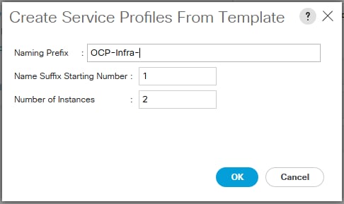


6. After the server pool and service profile association completes, all the services profiles can be seen in the associated state as shown below.

![]() Similarly, for Dev/ Test architecture, we have three Service Profile Templates - one for Master, the other two are for the combination of App and Infra nodes, and for App and Storage nodes. As two of App nodes are co-located with Infra and three of App nodes are co-located with Storage:
Similarly, for Dev/ Test architecture, we have three Service Profile Templates - one for Master, the other two are for the combination of App and Infra nodes, and for App and Storage nodes. As two of App nodes are co-located with Infra and three of App nodes are co-located with Storage:

Red Hat Enterprise Linux Atomic Host OS Installation
UCS Manager’s vMedia policy feature is used in this solution to enable automated bare metal OS installation. The installation process gets initialized automatically once the service profiles are associated.
1. vMedia policy at UCS Manager for CIMC mounted CD/DVD and HDD image files, needed for bare metal install
2. A web server hosting Boot ISO, kickstart HDD image and rest of the installation media
3. Boot policy having vMedia devices to be available for bootstrapping and subsequent operating system install
Following steps indicates the stages of automated OS install:
1. Once the service profiles association is complete, the boot ISO is automatically picked up for booting kernel and kickstart image file for RHEL Atomic Host 7.5 installation. This automated bare metal OS install happens as per the vMedia Policy configuration defined in UCSM.

2. RHEL 7.5 Atomic Host installation in progress.


3. Server reboots after the OS installation.
4. Host OS comes up and is ready for Red Hat OpenShift Container Platform deployment.
Provisioning - OpenShift Container Platform
In this section, we are going to provide detailed instructions to install OpenShift Container Platform 3.9 with container-native storage on freshly installed nodes as we get from previous steps. To start with all 12 nodes for production use case and 8 nodes for dev/ test uses case, are identical and there are no assigned entities to them for running the OpenShift Container Platform services. While we deploy the platform using Ansible Playbooks, different services and roles get assigned to each of the nodes at various stages. Once Bastion node is setup and configured as describe in the earlier section, following are the main tasks involved in the entire process:
1. Cloning the OpenShift-UCSM Repository
2. Inventory File Creation
3. Provisioning Bastion Node
4. Node Preparation for Red Hat OpenShift Container Platform Deployment
5. Setting up Multi-Master HA – Keepalived Deployment
6. Red Hat OpenShift Container Platform Deployment
7. Deployment Validation
![]() Steps 3, 4 and 5 are to be executed using Intel and Cisco developed Ansible Playbook code. Step 6 is to be executed using Red Hat provided set of Playbooks “openshift-ansible”.
Steps 3, 4 and 5 are to be executed using Intel and Cisco developed Ansible Playbook code. Step 6 is to be executed using Red Hat provided set of Playbooks “openshift-ansible”.
Cloning/Getting OpenShift-UCSM Ansible Playbook code from the GitHub repository
For the solution to work on UCS managed bare-metal servers there are specific configuration needs while preparing nodes for the actual OpenShift Container Platform deployment. In addition to this the Bastion node requires provisioning of services and configuration before it can be used as deployment host for OpenShift Container Platform through Ansible Playbooks execution. This solution also recommends to configure and setting up a multi-master HA using Keepalived in order to provide load balance and failover functionality for the OCP Infra nodes services, registry services and portal access.
All these configuration and service deployment tasks are automated through Ansible Playbook code jointly developed by Intel and Cisco solution team. The Ansible Playbook code is hosted in UCS GitHub repository.
1. If the Playbooks need to be further customized, clone the repository:
2. To get the released bits:
3. This method is recommended one for the solution. Un-tar the archive –
![]() Directory ‘src’ has the complete Ansible Playbook code. While hosts-ProdUseCase.example file is a sample inventory file to be used to deploy OpenShift Container Platform cluster.
Directory ‘src’ has the complete Ansible Playbook code. While hosts-ProdUseCase.example file is a sample inventory file to be used to deploy OpenShift Container Platform cluster.
All OpenShift-UCSM Ansible Playbooks for preparation work will be sourced from `src` directory and executed accordingly.
Ansible Playbook Structure – OpenShift-UCSM Playbook
1. There are 4 main modules in this Playbook: bastion-config, prerequisites, keepalived-multimaster and cluster-scaling:
Except for cluster-scaling module, all are needed to run for OCP deployment preparation. Cluster-scaling module used for scaling the existing cluster by adding either application and/or master nodes. Same module can be used for co-hosted etcd scaling as well.
For deployment preparation bastion-config, keepalived-multimaster and prerequisites modules are required. Each of these modules have codes spread, based on Ansible standards.
2. bastion-config as name suggest, is for bastion-node provisioning and has 2 roles, namely – deploy_basion and firewall:
![]() This Playbook creates dnsmasq container and run it as systemd service on bastion nodes. It also configures the firewall rules for dns, NAT and masquerading between private & public network. Configuration parameters are defined in inventory file.
This Playbook creates dnsmasq container and run it as systemd service on bastion nodes. It also configures the firewall rules for dns, NAT and masquerading between private & public network. Configuration parameters are defined in inventory file.
3. pre-requisites has following roles. These roles are self-explanatory:
![]() As the role names suggest in this Playbook, main job of it is to run the OpenShift DNS services on the bastion node, configure rhsm.conf for proxy, configure and run Chronyd services for NTP, subscribing to Red Hat Subscription Management (RHSM) and attaching required repos on all the nodes including Bastion node.
As the role names suggest in this Playbook, main job of it is to run the OpenShift DNS services on the bastion node, configure rhsm.conf for proxy, configure and run Chronyd services for NTP, subscribing to Red Hat Subscription Management (RHSM) and attaching required repos on all the nodes including Bastion node.
4. keepalived-multimaster Playbook code has following roles and task items –
![]() This Playbook builds and runs keepalived container on Infra nodes. After building keepalived container image, the Playbook runs it as a systemd service. Configuration parameters to run the keepalived container service are part of the inventory file.
This Playbook builds and runs keepalived container on Infra nodes. After building keepalived container image, the Playbook runs it as a systemd service. Configuration parameters to run the keepalived container service are part of the inventory file.
Inventory File Creation
Ansible Playbook execution requires an inventory file to perform tasks on multiple systems at the same time. It does this by selecting portions of systems listed in Ansible’s inventory, which defaults to being saved in the location /etc/ansible/hosts on the Bastion node for this solution. This inventory file consists of Hosts and Groups, Host Variables, Group Variables and behavioral Inventory Parameters.
This inventory file is customized for the Playbooks we used in this solution for preparing nodes and installing OpenShift Container Platform. The inventory file also describes the configuration of our OCP cluster and include/exclude additional OCP components and their configs.
OpenShift-UCSM repo has an example host.example file tested and validated with its entire configuration parameters for deploying OpenShift Container Platform on UCS managed bare metal servers.
Copy hosts*.example file from downloaded and extracted OpenShift-UCSM repo tar file on the bastion node to /etc/ansible/hosts:
· For Production use case Topology
· For Dev/ Test use case Topology
Following table briefly describe sections/groups used in the inventory file -
Table 9 Inventory file sections and their descriptions
| Sections | Description |
|
| [OSEv3:children] | - This section defines set of target systems on which Playbook tasks will be executed - Target system groups used in this solution are – masters, nodes, etcd, lb, local and glusterfs - glusterfs host group are the storage nodes hosting CNS and Container Registry storage services |
|
| [OSEv3:vars] | - This section is used for defining OCP Cluster variables - These are environmental variable that are used during Ansible install and applied globally to the OCP cluster | |
| [local] | - This host group points to the Bastion node - All tasks assigned for host group local gets applied to Bastion node only - This host group is used by OpenShift-UCSM Playbooks | |
| [masters] | - All master nodes, ocp-mstr-1/2/3.ocp-cvd.local are grouped under this section - They are set to `containerized=True` resulting in all master node services e.g. Controller Manager, Scheduler, Etcd data store, API services running as infra containers - `openshift_schedulable` variable is not defined in order to stop Kubernetes orchestrator deploy application pods on them | |
| [nodes] | - Host group contains definition of all nodes that are part of OCP cluster including master nodes - Both `containerized` and `openshift_schedulable` is set to true except for master nodes | |
| [etcd] | - Host group having nodes which will run etcd data store services - In this solution master node co-host etcd data store as well, hence host ips are the same master node ip addresses - Host names given are etcd1/2/3.ocp-cvd.local. These names will resolve to master node hosts | |
| [lb] | - This host group is for nodes which will run load-balancer – OpenShift_loadbalancer/haproxy-router - This group will have same infra nodes IPs as Infra nodes runs the load-balancing services along with container registry and keepalived services | |
| [glusterfs] | - All storage nodes are grouped together under this - CNS services run on these nodes as glusterfs PODs - `glusterfs_devices` variable is used to allocate physical storage JBOD devices for container-native storage | |
![]() For Dev/ Test Use case topology, Infra nodes have `openshift_schedulable` variable set to `True` in order to co-host application pods with infra pods. Similarly, Application Nodes co-host the container-native storage services hence [glusterfs] host group have all application nodes listed.
For Dev/ Test Use case topology, Infra nodes have `openshift_schedulable` variable set to `True` in order to co-host application pods with infra pods. Similarly, Application Nodes co-host the container-native storage services hence [glusterfs] host group have all application nodes listed.
Table 10 Inventory key variables used in this solution and their descriptions
| Key Variables | Description |
| deployment_type=openshift-enterprise openshift_release=v3.9 openshift_image_tag=v3.9.27 os_sdn_network_plugin_name ='redhat/openshift-ovs-multitenant' openshift_http/https_proxy | - With this variable OpenShift Container Platform gets deployed
- OCP release version as used in this solution
- Container Image tag used to avoid compatibility issues between various OpenShift Container Platform components
- This variable configures which OpenShift SDN plug-in to use for the pod network, which defaults to redhat/openshift-ovs-subnet for the standard SDN plug-in. `redhat/openshift-ovs-multitenant` value enable multi-tenancy
- These 2 variables are required if the setup is behind the proxy. OpenShift Ansible Playbook configures this on all cluster nodes for container image download from the external repository |
| openshift_hosted_manage_registry=true openshift_hosted_registry_storage_kind=glusterfs openshift_hosted_registry_storage_volume_size=200Gi | - These variables make Ansible Playbook to install OpenShift managed internal image registry
- Storage definition for the image repository. In our Solution we use GlusterFS as back-end storage
- Pre-provisioned Volume size for the repo. |
| openshift_master_dynamic_provisioning_enabled=True openshift_storage_glusterfs_storageclass=true openshift_storage_glusterfs_storageclass_default=true
openshift_storage_glusterfs_block_deploy=true |
- To enable dynamic storage provisioning while cluster is getting deployed and any subsequent application pod requiring persistent volume/persistent volume claim
- To create a storage class. In this solution we rely on a single default storage class, as we have a single 3 node storage cluster have identical set of internal drives
- Making storage class default, so that PV/PVC can be provisioned through CNS by provisioner plugin. In our solution its kubernetes.io/glusterfs
- Enabling Container-native storage service to provision block storage. Block storage is needed for Metrics and Logging components |
More details on various OpenShift environment variables can be found here - https://access.redhat.com/documentation/en-us/openshift_container_platform/3.9/html-single/installation_and_configuration/#configuring-ansible
Provisioning Bastion Node
Under this step, dnsmasq_container service is created and firewall rules are set on the bastion node. dnsmasq_container.service runs OpenShift DNS server to serve name service requests from OpenShift Container Platform cluster nodes.
Execute following command to provision bastion node –
Play recap status shows Playbook execution was successful and we can move forward to next step.
Node Preparation for OpenShift Container Platform Deployment
After successful OS deployment, nodes must be prepared for OpenShift Container Platform installation. Following preliminary steps must be performed by user: prepare accounts and ssh keys across all nodes, software licenses subscription, configuring DNS and Docker Engine. All tasks can be are automated, but can be performed manually per Red Hat’s documentation.
Start the Playbook by entering the following command:
This completes the node setup prep work for all the participating cluster nodes. Next step is to install multi-master HA using keepalived deployment.
Setting up Multi-Master HA - Keepalived Deployment
To achieve HA, maximum fault tolerance, and performance, this solution includes an additional Keepalived component. Keepalived is open-source software distributed under GPL license. It is recognized by Red Hat as a recommended solution, and this implementation is based on the official Red Hat Enterprise Linux documentation. This CVD uses HA-Proxy instances (in both flavors), which are spawned as Docker containers on both infra nodes. In conjunction with floating IP address provided by Keepalived, a single point of failure is eliminated. Installation and configuration can be performed manually or through a single command (using Ansible Playbook).
In order to use automatic keepalived Ansible Playbooks the following variables must be defined in the OSEv3:vars section in Ansible inventory:
Table 11 Key variable used for Keepalived component in the Ansible Inventory file
| Variable | Purpose |
| external_interface | To get attached with external subnet floating IP(VIP) by Keepalived daemon |
| internal_interface | To get attached with internal subnet floating IP(VIP) by Keepalived daemon |
| openshift_master_cluster_ip | IP address to access API services internally |
| openshift_master_cluster_public_ip | IP address to access API services externally and WebUI/OpenShift Container Platform Dashboard |
To deploy Keepalived daemons using an Ansible Playbook on infrastructure nodes, enter following command inside the forked Git repository:
Red Hat OpenShift Container Platform Deployment
This solution recommends using advanced installation method for deploying OpenShift Container Platform with container-native storage on UCS managed servers. This provides greater control over cluster configuration through Ansible inventory file configuration options.
We have used containerized installation path to deploy the platform which installs services using container images and runs separate services in individual containers. Containerized method is the only available options on Red Hat Enterprise Linux Atomic Host systems and is automatically selected for us based on the detection of the /run/ostree-booted file. With containerized installs, each component of OpenShift Container Platform is shipped as a container (in a self-contained package) and leverages the host’s kernel to start and run. Any updated, newer containers replace any existing ones on the cluster nodes.
Red Hat has developed a set of Playbooks “openshift-ansible”. The Playbooks is installed using openshift-ansible rpm which is part of rhel-7-server-ose-3.9-rpms repos. This repos and rpm installation gets configured on the Bastion node when the “prerequisite/nodes_setup” Playbooks are run.
The main installation Playbook /usr/share/ansible/openshift-ansible/playbooks/deploy_cluster.yml runs a set of individual component Playbooks in a specific order, and the installer reports back at the end what phases it has gone through. If the installation fails during a phase, we are notified on the screen along with the errors from the Ansible run.
Table 12 List of components for deployment using deploy_cluster Playbook
| Component | Purpose |
| Health Check | Playbooks for detecting potential problems prior to an installation |
| etcd | etcd data store installation |
| Load Balancer | OpenShift HaProxy Loadbalancer Configuration |
| Master | Master service installation |
| Master Additional Components | Additional Components e.g. manageiq, hosted templates |
| Nodes | Node service installation |
| GlusterFS | OpenShift GlusterFS Cluster Configuration, a new, natively-hosted GlusterFS cluster. GlusterFS pods deployment on nodes in the OpenShift cluster which are configured to provide storage. |
| Hosted | OpenShift Hosted Resources - OpenShift Router and OpenShift Registry |
| Web Console | OpenShift Dashboard |
| Service Catalog | Application Service Catalog installation |
| Metrics** | OpenShift Metrics – (Optional) not part of default installation. See Appendix I |
| Logging** | OpenShift Logging, EFK stack – (Optional) not part of default installation. See Appendix I |
Below are the steps for deploying OpenShift Container Platform cluster.
1. Run the prerequisite.yml Playbook. This must be run only once before deploying a new cluster:

2. Next, run the deploy_cluster.yml Playbook to initiate the cluster installation:

Deployment Validation
In this section we will go through series of deployment verification tasks. These include both UI and CLI tasks. After the installation completed successfully as we saw before, run through the following steps:
1. Verify if the master is started and nodes are registered and reporting `Ready` status. On one of the master node, run the following as root:
![]() In order to provide `admin` user cluster-admin role, execute following command on the master node:
In order to provide `admin` user cluster-admin role, execute following command on the master node:
[root@OCP-Mstr-1 ~]# oc adm policy add-cluster-role-to-user cluster-admin admin --as=system:admin
cluster role "cluster-admin" added: "admin"
This allows admin user to act as cluster-admin user and can manage cluster wide projects.
2. Verify if the web console is installed correctly. Use `openshift_master_cluster_public_hostname` value, as defined in inventory file, as the URL for web-console access - `https://ocp-cvd.cisco.com:8443`:

![]() Make sure URL hostnames are resolvable through external dns otherwise these names should be added to /etc/hosts pointing to `openshift_master_cluster_public_ip`.
Make sure URL hostnames are resolvable through external dns otherwise these names should be added to /etc/hosts pointing to `openshift_master_cluster_public_ip`.
![]() We have used htpasswd utility for authenticating users to log into Red Hat OpenShift Container Platform. However, existing authentication methods like LDAP, AD etc can also be used.
We have used htpasswd utility for authenticating users to log into Red Hat OpenShift Container Platform. However, existing authentication methods like LDAP, AD etc can also be used.

3. Verify for OpenShift Integrated Container Registry console access, by clicking on registry console URL as displayed on dashboard under default project:


4. Verify etcd cluster health and membership status. Login to one of the master node and run following commands:
5. Client setup – In this step we will setup OpenShift client `oc` on the bastion node and use this client to execute rest of the steps and validate the deployment.
6. Download and install OpenShift v3.9 Linux Client from this URL: https://access.redhat.com/downloads/content/290
7. Extract oc-3.9.31-linux.tar and copy `oc` binary to /usr/bin/ and /usr/sbin/
8. Access OpenShift Web Console and click on `?` on top right corner.

9. Copy login command with token from here –
![]()
10. Use copied command on the Bastion node to login to OpenShift Container cluster:
11. Login through cli client `oc` can be done without having to supply authentication token by using `insecure` connection as below:
12. In this method, we need to supply user-name and password.
13. Verify container-native storage PODs and other resources are running:
14. Verify Gluster cluster status and storage resource health by logging in to one of the glusterfs-storage pods:
15. Verify storage class created as part of deployment:
16. Verify Router and Registry Health, value in the DESIRED and CURRENT field should match -
17. Verify PODs are distributed on desired Infra nodes:
18. Verify API service and web console health – Both the API service and web console are sharing the same port, TCP 8443. This port needs to be available within the cluster and to everyone who needs to work with the deployed environment.
19. Verify complete environmental health by creating a sample project and deploying application pod.
a. Create a new project named `sample-test`:
b. Deploy a sample application `cakephp-mysql-example`:
c. After successful completion of the build, we should see 2 pods running – an application and a database pod:
d. Verify application URL access –

Dashboard – UI Operations
This section describes the use of UI to create a project and deploy a sample application from the service catalog. Below are the steps to follow:
1. Verify complete environmental health by creating a sample project and deploying application pod
2. Login to OpenShift dashboard with admin user, click on Create Project Button.

o Create a new project “admin-test” and leave rest of the fields as is.

3. Select admin-test project under project-list and click on Browse Catalog. From the catalog window click on CakePHP+MySQL application item.

4. Click Next on the following window.

5. On the configuration tab, keep all the default values and click the create button.

6. CakePHP+MySQL application starts building at the background.

7. We can monitor application build status by navigating Overview -> cakephp-mysql-persistent.

8. Once build gets complete we can see application pods running.

9. Verify PVC attachment to mysql instance running on the application pod.

10. On cli, get the application pod and pvc status verified as below:
Test Plan
This section summarizes various test scenarios during solution validation exercise.
Functional Test Cases – OCP/container-native storage
OCP Installation
1. Installation on UCS managed bare metal servers as per reference architecture topologies for both Production and Dev/ Test use cases. Complete installation on dedicated nodes as in Production use case topology as well as co-hosted environment as in Dev/ Test use case.
2. Automated solution deployment on the servers including bare metal provisioning.
3. Single workflow based automated installation including container-native storage component.
4. Post deployment checks on the entire OpenShift Container Platform stack. For example:
- Etcd cluster health/member list
- Router and Registry health checks
- DNS validation
- APIs and Web Console access validation
- Sample project creation and application pod deployment
OpenShift Integrated Registry operations
Pulling/ pushing images, registry console access and deploying application pods from the image registry
Application Pod deployment
1. Standalone sample application pod
2. Multi-tier sample application pod
3. Application pod deployment with PVC
4. Scaling up/down application pod to desired numbers using deployment configuration
5. Scaling application pods to maximum supportable limit. This solution has 4 application nodes which can accommodate roughly 1000 pods @250 pods per node. We have successfully tested this limit without any issue.
Persistent Volume and Persistent Volume Claims
1. PV create/delete
2. PV claims by application pod
3. Dynamic provisioning of PV/PVC
4. Multi-tier application pod deployment with PVC binding
5. Application pod with PVC, migration to other application node. Data consistency validation.
6. Reclaiming PV on a different application pod, data persistency validation.
High-Availability Tests
Component HA
1. Registry services – Infra node reboot/shutdown without any disruption in registry access
2. Router services – Infra node reboot/shutdown tests, no service outages on multi-tier application pod access
3. etcd cluster services – Master node reboot/shutdown tests, etcd services remained un-affected and application pod deployment/deletion successful on downgraded etcd cluster
4. API services – Master node reboot/shutdown test – API services remains un-affected
5. Controller Manager - Master node reboot/shutdown test – Controller manager service remains un-affected
6. Infra node – Infra node reboot/shutdown – Cluster remains 100% operational
7. Storage nodes – Downgraded CNS cluster still operates without any storage service disruption except new PV/PVC operation. Creation of new physical volume and claim get restored once storage cluster node comes back online
![]() Container-native storage services runs from a 3-node cluster. In this solution the replication factor is set to ‘3’, which means a minimum 3-storage nodes are required. This solution design tolerates single storage node failure. All existing storage resources continue to operate as-is and without any service disruption in the event of single node failure and any new PV/PVC operation cannot be done during the failure window. Resumption of failed storage node restores all operations to its original state.
Container-native storage services runs from a 3-node cluster. In this solution the replication factor is set to ‘3’, which means a minimum 3-storage nodes are required. This solution design tolerates single storage node failure. All existing storage resources continue to operate as-is and without any service disruption in the event of single node failure and any new PV/PVC operation cannot be done during the failure window. Resumption of failed storage node restores all operations to its original state.
8. UCS Component HA test – one of Fabric Interconnects and upstream N9K switches reboot simultaneously or one-by-one, and does not affect the Infrastructure and underlying OpenShift Container Platform cluster access and both remains fully operational.
Scaling-up OpenShift Container Platform Cluster Tests
Cisco UCS infrastructure has a built-in mechanism to scale the deployed application environment through service profile templates and server pool concepts. scaling-up infrastructure is easy and just few clicks needed to accomplish it. Inserting new blade/rack server hardware and adding it into the server pool, UCS manager gets it discovered and associate a new service profile to it automatically. Once the service profile is associated vMedia policy kicks in to install Red Hat Enterprise Linux Atomic Host on the bare metal node automatically.
Once new host comes online, existing Ansible inventory is used to manually add the new node into the existing cluster. Depending on node role assigned to the new host, Ansible inventory files configuration parameters added and respective scaleup.yml Playbook execution needed. This section describes step-by-step procedure to add an Application and Master node to the existing cluster.
Application Node scaling
1. Insert a new blade in any available chassis slot and get it discovered:

2. Add the server to Application node server pool and create new service profile from the application node service profile template:


3. Service profile association will automatically kick in as the template was already associated to the server pool:

4. While service profile getting associated, we created kickstart HDD image for the new node. Steps outlined for the same in earlier sections.
5. After completion of successful service profile association our automated OS installation workflow will commence and install OS through vMedia mounted boot and kickstart images:


6. Post Atomic Host installation, modify Ansible inventory file to include new node. Add new_nodes group under [OSEv3:children] and a new group [new_nodes] with new host (OCP-App-5) configuration parameters as below:
7. Next step is to run cluster_scaling.yml Playbook which is part of OpenShift-UCSM Ansible repo. This Playbook installs and configures required utilities, subscription etc on the new node:
8. Now that new node is ready to get added to the existing OCP cluster. For adding new node we run Red Hat provided nodes scaleup.yml Playbook as below:
9. Log in to OCP cluster using cli and check the nodes health status:
10. Verify newly added application node gets application pod schedulable on it. This can either be done through deploying new application pod or scaling existing pod. We choose later option to validate:
Master Node scaling
Steps for scaling master nodes remains the same as that of the application node scaling from step 1 through 5. New hardware needs to be added to OCP-Mstr server pool and service profile should be instantiated from OCP-Mstr template. Follow the steps to complete a master node addition:
1. Modify Ansible inventory to include new_nodes under [OSEv3:children], add new master (OCP-Mstr-4) in [new_nodes] section, create [new_masters] section and add new master in [new_masters] section as below:
2. Run cluster_scaling.yml for preparing the node for adding it to the existing cluster:
3. Add the new master to the existing OCP cluster using scaleup.yml Playbook:
4. Log in to OCP cluster using cli and check the nodes health status:
Bill of Materials
The following infrastructure components are required for Production Use Case Architecture:
| Component | Model | Quantity | Description |
| App nodes | B200M5 (UCSB-B200-M5-U) | 4 | CPU – 2 x 6130@2.1GHz,16 Cores each Memory – 24 x 16GB 2666 DIMM – total of 384G SSDs – 2x960GB 6G SATA -EV (Intel S4500 Enterprise Value) Network Card – 1x1340 VIC + 1xPort Expander for 40Gig network I/O Raid Controller – Cisco MRAID 12 G SAS Controller |
| Master nodes | B200M5 (UCSB-B200-M5-U) | 3 | CPU – 2 x 4114@2.2GHz,10Cores each Memory – 12 x 16GB 2400 DIMM – total of 192G SSDs – 2x240GB 6G SATA -EV Network Card – 1x1340 VIC + 1xPort Expander for 40Gig network I/O Raid Controller – Cisco MRAID 12 G SAS Controller |
| Infra nodes | B200M5 (UCSB-B200-M5-U) | 2 | CPU – 2 x 4114@2.2GHz,10Cores each Memory – 12 x 16GB 2400 DIMM – total of 192G SSDs – 2x240GB 6G SATA -EV Network Card – 1x1340 VIC + 1xPort Expander for 40Gig network I/O Raid Controller – Cisco MRAID 12 G SAS Controller |
| Bastion node | C220M5SX (UCSC-C220-M5SX) | 1 | CPU – 2 x 4114@2.2GHz,10Cores each Memory – 12 x 16GB 2400 DIMM – total of 192G HDDs – 2x300GB12GSAS10KSFF Network Card – 1x1385 VIC RAID Controller - Cisco MRAID 12 G SAS Controller |
| Storage nodes | C240M5SX (UCSC-C240-M5SX) | 3 | CPU – 2 x 6130@2.1GHz,16 Cores each Memory – 12 x 16GB 2666 DIMM – total of 192G SSDs – 2x240GB 6G SATA -EV SSDs - 20x3.8TB SATA (Intel S4500 Enterprise Value) Network Card – 1x1385 VIC Raid Controller – Cisco MRAID 12 G SAS Controller |
| Chassis | UCS 5108 (N20-C6508) | 2 |
|
| IO Modules | IOM2304 (UCS-IOM-2304=) | 4 |
|
| Fabric Interconnects | UCS 6332-16UP (UCS-FI-6332-16UP=) | 2 |
|
| Switches | Nexus 9396PX (N9K-C9396PX) | 2 |
|
| Red Hat OpenShift/On-Prem Subscription | SKU – SER0423 (?) | 13 (?) | Included Red Hat OpenShift Container Platform, Red Hat Enterprise Linux Atomic Host (?) |
| Red Hat Gluster Storage | SKU - RS0121353 (?) | 3 (?) | Includes CNS (?) |
The following infrastructure components are required for Dev/ Test Use Case Architecture:
| Component | Model | Quantity | Description |
| Application+Storage nodes co-located | C240M5SX (UCSC-C240-M5SX) | 3 | CPU – 2 x 4114@2.2GHz,10Cores each Memory – 12 x 16GB 2400 DIMM – total of 192G HDDs – 2x300GB12GSAS10KSFF(Internal Boot Drives) HDDs – 20x1.2TB12GSAS10KSFF Network Card – 1x1385 VIC Raid Controller – Cisco MRAID 12 G SAS Controller |
| Application+Infra | C240M5SX (UCSC-C240-M5SX) | 2 | CPU – 2 x 4114@2.2GHz,10Cores each Memory – 12 x 16GB 2400 DIMM – total of 192G HDDs – 2x300GB12GSAS10KSFF(Internal Boot Drives) Network Card – 1x1385 VIC Raid Controller – Cisco MRAID 12 G SAS Controller |
| Master nodes | C220M5SX (UCSC-C220-M5SX) | 3 | CPU – 2 x 4114@2.2GHz,10Cores each Memory – 12 x 16GB 2400 DIMM – total of 192G HDDs – 2x300GB12GSAS10KSFF Network Card – 1x1385 VIC Raid Controller – Cisco MRAID 12 G SAS Controller |
| Bastion node | C220M5SX (UCSC-C220-M5SX) | 1 | CPU – 2 x 4114@2.2GHz,10Cores each Memory – 12 x 16GB 2400 DIMM – total of 192G HDDs – 2x300GB12GSAS10KSFF Network Card – 1x1385 VIC RAID Controller - Cisco MRAID 12 G SAS Controller |
| Fabric Interconnects | UCS 6332-16UP (UCS-FI-6332-16UP=) | 2 |
|
| Switches | Nexus 9396PX (N9K-C9396PX) | 2 |
|
| Red Hat OpenShift/On-Prem Subscription | SKU – SER0423 (?) | 13 (?) | Included Red Hat OpenShift Container Platform, Red Hat Enterprise Linux Atomic Host (?) |
| Red Hat Gluster Storage | SKU - RS0121353 (?) | 3 (?) | Includes CNS (?) |
Solution involving Cisco UCS Infrastructure and Red Hat OpenShift Container Platform with container-native storage solution has been created to deliver a production-ready foundation that simplifies the deployment process, shares the latest best practices, and provides a stable, highly available environment to run your containerized production applications. This reference architecture covers the process of provisioning and deploying a highly available OpenShift Container Platform cluster on a private cloud environment with both the registry and the application pods backed by container-native storage solution from Red Hat.
The integration of Red Hat OpenShift Container Platform with container-native storage solution on Cisco UCS infrastructure enabled through automation tools like UCS Python SDK and Ansible facilitates container application platform to get deployed and managed quickly at scale. It also provides a very good starting point for enterprise IT to make inroads into DevOps and CI/CD model for application environment for quick business turn around. Enterprises can accelerate on the path to an enterprise-grade Kubernetes solution with Red Hat OpenShift Container Platform running on Cisco UCS infrastructure.
This Cisco validated design and deployment guide aims to deliver a turnkey end-to-end solution running on a cluster of servers based on the latest Intel® technologies—enabling customers to focus their resources on developing innovative applications instead of planning, deploying, and managing entire on-premises cloud infrastructure.
Appendix – I: Additional Components – Metrics and Logging Installation
Metrics can be deployed using glusterfs volumes. It can work with both file-system base and block volume storage options.
In order to get the glusterfs-block-provisioner installed while bringing up the OCP cluster using `deploy_cluster.yml` playbook, following RHEL Atomic Host OS type validation code need commenting out:
With this Ansible Playbook code change, glusterfs-block-provisioner pod comes up as part of Container-native storage component installation:
Metrics
Metrics is configured to view CPU, memory and network-based metrics from the OpenShift Container Platform web console and are available for use by horizontal pod auto-scalers.
The kubelet exposes metrics that can be collected and stored in the backend by Heapster. As an OpenShift Container Platform administrator, one can view a cluster’s metrics from all containers and components in one user interface. These metrics are also used by horizontal pod auto-scalers in order to determine when and how to scale.
Metrics describes how to install Hawkular Metrics as a metrics engine which stores the data persistently in a Cassandra database.
1. The OpenShift Container Platform Ansible openshift_metrics role configures and deploys all of the metrics components using the variables from the Ansible inventory file. Following variables needed in the inventory file to install metrics on the existing OpenShift Container Platform cluster:
![]() Metrics component need to have – a. Running OCP cluster, b. Gluster storage class. Metrics can use either Gluster Block Storage Class (recommended) or GlusterFS storage class.
Metrics component need to have – a. Running OCP cluster, b. Gluster storage class. Metrics can use either Gluster Block Storage Class (recommended) or GlusterFS storage class.
Metrics Ansible role should be run after OpenShift Container Platform gets successfully deployed.
2. To install metrics component on the OCP cluster, have inventory variables as mentioned above defined then run:
This shows that the Metrics installation is complete.
3. To validate whether all the metrics resources are running fine, login to the cluster through cli and switch to the project “openshift-infra”:
4. We can also validate via OpenShift Web Console:


Logging
The Logging allows to collect and aggregate event logs from the cluster and provides a dashboard to view/ search events.
The Elasticsearch, Fluentd, and Kibana (EFK) stack aggregates logs from nodes and applications running inside OpenShift Container Platform installation.
Once deployed it uses Fluentd to aggregate event logs from all nodes, projects, and pods into Elasticsearch (ES). It also provides a centralized Kibana web UI where users and administrators can create rich visualizations and dashboards with the aggregated data. Fluentd bulk uploads logs to an index, in JSON format, then Elasticsearch routes search requests to the appropriate shards.
As an OpenShift Container Platform cluster administrator, we can deploy the EFK stack to aggregate logs for a range of OpenShift Container Platform services. Application developers can view the logs of the projects for which they have view access. The EFK stack aggregates logs from hosts and applications, whether coming from multiple containers or even deleted pods.
The EFK stack is a modified version of the ELK stack and is comprises:
1. Elasticsearch (ES): An object store where all logs are stored.
2. Fluentd: Gathers logs from nodes and feeds them to Elasticsearch.
3. Kibana: A web UI for Elasticsearch.
Once deployed in a cluster, the stack aggregates logs from all nodes and projects into Elasticsearch and provides a Kibana UI to view any logs. Cluster administrators can view all logs, but application developers can only view logs for projects they have permission to view. The stack components communicate securely.
1. The EFK stack is deployed using an Ansible Playbook made for the EFK components. The OpenShift Container Platform Ansible openshift_logging role configures and deploys all of the logging components using the variables from the Ansible inventory file. Following variables needed in the inventory file to install Logging/EFK stack on the existing OpenShift Container Platform cluster:
![]() Logging/EFK components have same dependencies as that of metrics component – a. Running OCP cluster, b. Gluster Block Storage Class. Logging can be installed using block volumes only; Red Hat does not recommend running block volumes on Atomic Host for the lack of support for multipath on iSCSI targets. This makes the feature still a Tech Preview feature. The Ansible role “Logging” should be run after OpenShift Container Platform gets successfully deployed.
Logging/EFK components have same dependencies as that of metrics component – a. Running OCP cluster, b. Gluster Block Storage Class. Logging can be installed using block volumes only; Red Hat does not recommend running block volumes on Atomic Host for the lack of support for multipath on iSCSI targets. This makes the feature still a Tech Preview feature. The Ansible role “Logging” should be run after OpenShift Container Platform gets successfully deployed.
2. To install metrics component on the OCP cluster, have inventory variables as mentioned above defined then run:
This shows that the Logging installation is complete.
3. To validate whether all the logging resources are running fine, login to the cluster through cli and switch to the project “Logging”:
We see all the logging stack pods are up and running.
Appendix – II: Persistent Volume Claim/Application Pod – yml file usage
This appendix gives details on how to create PVC using a yaml file and using the same PVC in an application pod through yaml definitions. Here is the storage provisioning workflow:
· Create multiple persistent volumes (PV) and register these volumes with OpenShift.
· Developers then submit a persistent volume claim (PVC). PV gets created on the fly, if not available beforehand.
· A PV is identified and selected from a pool of available PVs and is bound to the PVC.
· The OpenShift pod then uses the PV for persistent storage.
Figure 9 Persistent Volume Request – Container-native Storage for Red Hat OpenShift Container Platform

Here is how heketi URL is used in storageclass object for storage provisioning requests:
PVC Creation
1. Here is the sample file which we can use to create a persistent volume claim on default storage class. This will create a 10Gig volume.
2. To create a PVC using above definition, run the following command on any of your choice of project. We are using ‘test1’ project:
3. We see a pvc named ‘gluster1’ got created with access mode RWX.
Application Pod Deployment with PVC
1. To use the same PVC in an application, create a yaml file with application and storage definition as below:
2. To create an application named busybox using above yaml definition, run following command:
3. To check the volume mount, login to busybox container and validate:
Appendix – III: Disconnected Installation
Often data centers do not have access to internet, even via proxy servers. Sometimes even proxy servers become a bottleneck while we deploy OpenShift Container Platform with container-native storage. Advanced installation method using Ansible Playbooks rely on connectivity to Red Hat’s external container image repositories. Most of the OCP infrastructure services which runs inside independent containers, need those container images to be downloaded from the repos, build and deploy online. While installer Playbook is running, these images get downloaded on the fly and are used for building and deploying services for the OpenShift Container Platform.
As OpenShift Container Platform uses several containerized components, images get pulled in directly from Red Hat’s Docker registry. Setups that are behind proxy and/or slow down the connections to external repos, this could be a challenge while the deployment is in progress. Sometimes due to this, specific Ansible tasks times out during the Playbook execution and hence, the entire deployment fails.
In this solution we have pre-populated cluster nodes with required infra component images before executing deploy_cluster.yml Playbook, to overcome this issue.
1. On the bastion node pre-pull all required images
2. Save all downloaded images in a tar file using `docker save` command:
3. Transfer image tar file on all the cluster nodes:
4. Load image files on the destination nodes:
For more information on the list of images required for various components and additional inputs on disconnected installation, refer to Red Hat’s official installation and configuration guide for OCP 3.9 at: https://access.redhat.com/documentation/en-us/openshift_container_platform/3.9/html-single/installation_and_configuration/#install-config-install-disconnected-install
Appendix – IV: Uninstalling Container-native Storage
Rebuilding OpenShift Container Platform Cluster requires uninstalling container-native storage component from the cluster to clean up the storage devices. On failing to do this, fresh install on the cluster nodes would fail during Heketi pod deployment on the storage devices, as the storage devices would still have the reminiscence of previously configured PV/LV.
Red Hat OpenShift Container Platform 3.9 supports uninstalling container-native storage component through a separate Ansible Playbook. This might come in handy when there are errors in the inventory file options that can possibly cause the container-native storage services to get deployed incorrectly.
While removing the container-native storage installation, currently used storage references by the applications should be removed by cleaning up the applications. This includes infrastructures like Registry, Logging and Metrics that have PV claims created using the glusterfs-storage and glusterfs-storage-block Storage Class resources.
1. Remove Logging and Metrics:
ansible-playbook -e "openshift_logging_install_logging=false"
/usr/share/ansible/openshift-ansible/playbooks/openshift-logging/config.yml
ansible-playbook -e "openshift_logging_install_metrics=false"
/usr/share/ansible/openshift-ansible/playbooks/openshift-metrics/config.yml
2. Remove Registry:
oc delete deploymentconfig docker-registry
3. Uninstall container-native storage with specific varies to wipe out the storage devices for glusterfs before re-installing.
ansible-playbook -e "openshift_storage_glusterfs_wipe=True" –e "openshift_storage_glusterfs_registry_wipe=true" /usr/share/ansible/openshift-ansible/playbooks/openshift-glusterfs/uninstall.yml
A list of references that can come handy while deploying and administering this solution:
· Cisco UCS Infrastructure for Red Hat OpenShift Container Platform – Design Guide:
https://www.cisco.com/c/en/us/td/docs/unified_computing/ucs/UCS_CVDs/ucs_openshift_design.html
· Accelerate Application Development and Delivery – Cisco UCS and Red Hat OpenShift Container Platform Solution Brief:
· OpenShift-UCSM Ansible Playbooks GitHub repo – Cisco and Intel:
https://github.com/CiscoUcs/OpenShift-UCSM
· Introducing a Fully Integrated Turnkey Solution from Intel and Red Hat – Solution Brief:
· Red Hat OpenShift Container Platform 3.9 – Architecture:
· Installation and Configuration:
· Cluster Administration:
· Day Two Operations:
· CLI Reference:
Rajesh Kharya, Technical Leader, Cisco UCS Solutions Engineering, Cisco Systems Inc.
Rajesh Kharya is Tech lead with Solutions Engineering team, Computing System Product Group. His focus includes Open Source Technologies, Cloud, Software Defined Storage, Containers and Automation.
Sindhu Sudhir, Technical Marketing Engineer, Cisco UCS Solutions Engineering, Cisco Systems Inc.
Sindhu Sudhir is part of Cisco UCS Solutions Engineering team. In her current role she is focusing on Container technologies and infrastructure automation on Cisco UCS platform.
Lukasz Sztachanski, Cloud Solutions Engineer, Data Center Solutions Group, Intel
Focused on developing and designing cloud-orchestration stacks at Intel. His main areas of expertise are Kubernetes, OpenShift and Container-native technologies, where he emphasize hardware integration, performance and robustness. During his over-a-decade career he managed large DC in EMEA region and complex infrastructure for industry-leading SaaS company.
Lukasz Luczaj, Cloud Solutions Engineer, Data Center Solutions Group, Intel
From the beginning of his career he has been working on cloud technologies and software defined architectures with a strong focus on container-based solutions (Docker, Kubernetes, OpenShift). His goal is to optimize performance, provide reliability and make private cloud solutions enterprise ready according to the rule "Build it, Break It, Fix It". He is a strong enthusiast of open source and automation technologies.
Acknowledgements
· Cisco Systems: Vishwanath Jakka, Babu Mahadevan
· Intel: Seema Mehta, Scott Allen
· Red Hat: JP Jung, Chris Morgan, David Cain, Annette Clewett, Jose A.Rivera, Nolan Hayes, John Martin
 Feedback