CTI Server Message Reference Guide (Protocol Version 21) for Cisco Unified Contact Center Enterprise, Release 11.6(1)
Bias-Free Language
The documentation set for this product strives to use bias-free language. For the purposes of this documentation set, bias-free is defined as language that does not imply discrimination based on age, disability, gender, racial identity, ethnic identity, sexual orientation, socioeconomic status, and intersectionality. Exceptions may be present in the documentation due to language that is hardcoded in the user interfaces of the product software, language used based on RFP documentation, or language that is used by a referenced third-party product. Learn more about how Cisco is using Inclusive Language.
- Updated:
- July 13, 2017
Chapter: CTI Server Overview
CTI Server Overview
How CTI Server Works
The CTI Server provides an interface between Unified CCE and client CTI applications. CTI Server runs on either a Unified CCE Peripheral Gateway (PG) with ACD interface software or on a dedicated CTI Gateway platform. This figure shows a sample CTI system in which the CTI Server runs on a PG platform along with the ACD interface software. CTI Servers may be running at one or several call centers in the enterprise.
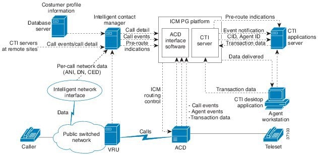
CTI Server forwards pre-routes indications to CTI application servers. Pre-route indications identify the caller and provide associated call attributes to applications before the call is connected to an agent or Voice Response Unit (VRU).
In a direct desktop application environment, call event information is delivered to the targeted desktop when the call is delivered. CTI Server reports call events and agent work state changes to the application as they occur through each stage of the call flow. This lasts from when a call arrives at an answering resource (Automatic Call Distributor (ACD), Private Branch Exchange (PBX), or VRU), until the caller hangs up.
Unified CCE Call Processing
The following brief review of several different Unified CCE call processing flows may be helpful when considering the CTI services and data provided by this interface. In the following discussions:
Agent represents either a human representative or a VRU port.
- ACD represents a peripheral that is directly monitored by Unified CCE. It may be an actual ACD or a VRU.
- Call context refers to the user data associated with a specific call collected by Unified CCE. Call context includes Dialed Number, Calling Line ID or ANI, Caller Entered Digits, and an array of Call Variables.
Pre-Routed Normal Call
A customer dials an Enterprise “800” number.
The caller responds to in-network prompting (if any).
The network forwards a route request to Unified CCE (including any caller entered digits collected by the network).
Unified CCE, through the use of a routing script, chooses a destination to handle the call. The routing script almost certainly makes use of any caller entered digits.
A route response is returned to the network.
The call arrives at the chosen ACD and is monitored by the Peripheral Gateway (PG).
The call may pass through several states (queued, alerting, etc.) before finally being connected to an agent.
The agent may either handle the call directly or transfer the call to another agent.
Upon completion of the call, a Termination Call Detail record is created and sent to the Central Controller (CC) database.
Translation Route Call
The caller responds to in-network prompting (if any).
The network forwards a route request to Unified CCE (including any caller entered digits collected by the network).
Unified CCE, through the use of a routing script, chooses two destinations for the call: an intermediate target and an ultimate target. The intermediate target is chosen from a special “pool” of targets reserved for just this purpose. No other calls are expected to arrive at the intermediate target.
A route response is returned to the network to send the call to the intermediate target. At the same time, the ultimate target data is sent to the PG monitoring the ACD where the call is expected to arrive. Caller entered digits collected in the network and any other call data set by the routing script is also sent to the PG in the message.
The call arrives at the chosen ACD and is monitored by the Peripheral Gateway (PG).
The ACD, recognizing the “special” nature of the call, performs a Route Request to collect the call’s ultimate target.
The ultimate target and other “call context” data determined by Unified CCE in step 5 is returned by the PG in a Route Response
The ACD routes the call to the ultimate target. As in the “normal” call case, the PG is informed of the call’s state changes as they occur. Eventually the call is connected to an agent.
The agent may either handle the call directly or transfer the call to another agent.
Upon completion of the call, a Termination Call Detail record is created and sent to the CC database.
Post Route Call
An ACD sends a Route Request to Unified CCE in order to determine the destination for a call it wishes to redirect. The Route Request may supply call data such as caller entered digits and any other call context data that peripheral type supports.
Unified CCE, through the use of a routing script, chooses a destination to handle the call. The routing script almost certainly makes use of any caller entered digits.
A route response is returned to the ACD, along with call context data (that may have been updated by the routing script).
The ACD routes the call to the ultimate target. As in the “normal” call case, the PG is informed of the call’s state changes as they occur. Eventually the call is connected to an agent.
The agent may either handle the call directly or transfer the call to another agent.
Upon completion of the call, a Termination Call Detail record is created and sent to the Central Controller database.
Transfer Call
In the case of a “local” transfer, the agent handling a call directs the ACD to transfer the call to another destination on the same ACD.
The peripheral gateway (PG) is informed of the various events associated with the call’s transfer.
Call transfers are handled differently by different types of ACDs. In general a new logical call is created for the resulting call. A Termination Call Detail record is created for the original call.
The new call is connected to an agent and is then handled or transferred (again) like any other call.
In the case of a “remote” transfer, the call leaves the realm of the monitoring PG and the original call is terminated in the usual way. The Unified CCE monitor the ACD and the "remote" transfer takes place into this ACD, the new call is monitored on that ACD's PG when the call arrives. This new call has none of the call context of the original call.
Depending upon the particular ACD’s capabilities and tie-line configuration, some ACDs may be set up to affect call transfers using the post route and translation route features previously described. In this case, the call context is preserved by being sent through Unified CCE via the route request and translation route mechanisms to the remote PG, and is thus available to the CTI Client, if any, associated with the destination device.
Conference Call
Like call transfers, call conferences are handled differently by different types of ACDs and may involve the creation of several calls that are all linked together.
CTI Server Configurations
The CTI Interface uses TCP/IP Ethernet for network connectivity to the CTI Server. You can use multi-protocol IP routers to provide connectivity to CTI clients on other types of LANs. You can use the Ethernet interface used for CTI client communication with the CTI Server for other purposes, such as the PG’s public network interface; a dedicated interface is not required.
 Note | Do not use the PG private network for CTI communication. |
Simplex/Duplex Configuration
In simplex configurations, there is one CTI Server on the local network with the CTI clients. In duplex configurations, two CTI Servers are present. There may be other equipment (for example, ACDs) on the network as well.

CTI Bridge Configuration
In CTI Bridge configurations, a CTI Bridge Client provides the connection between an existing CTI Application and Unified CCE, as shown in this figure.

CTI Bridge applications are interested in all call and agent state events that are occurring on the ACD. By comparison, agent workstation applications are interested only in the events associated with a particular agent device. The CTI Bridge application is a specially written program that converts or adapts the CTI messages into another format, as needed. A single CTI Bridge application provides such translation services for multiple agent desktops. The CTI Bridge application can be designed to interface with CTI Servers or similar applications on systems that are already in use in the call center.
Some examples of CTI Bridge applications include:
-
Message converter applications. For example, an application may convert the CTI message set to the message set of a foreign telephony server.
-
Server-to-server communication applications. For example, an application may enable the CTI Server to speak directly to a help desk application’s middle tier server.
CTI Server Message Set
The CTI Server makes call data available to applications in real time. To accomplish this task, the CTI Server process responds to requests from clients and originates unsolicited messages. All messages share a common message header and use the same set of data types.
This following table groups the messages into broad categories based on the nature of the message data.
|
Category |
Description |
|---|---|
|
Session Management |
Messages related to the establishment and maintenance of a client connection to the CTI Server. |
|
Miscellaneous |
Messages related to system-level events on the PG (for example, peripheral off-line, loss of PG-to-Central Controller communications). |
|
Call Events |
Messages related to call state changes. |
|
Agent Events |
Messages related to agent state changes. |
|
Call Data Update |
Messages related to CTI client modification of call data. |
|
Client Control |
Messages related to the direct control of agent state (for example, sign-in, sign-out) and control of inbound and outbound calls. |
 Feedback