CMM Provisioning Procedures for Release 7.4(x)
Available Languages
Table Of Contents
CMM Provisioning Procedures for Release 7.4(x)
Saving and Committing/Deploying the New Configuration
Provisioning System Components
Entering MML Names and Descriptions
Adding TDM Interfaces for T1/E1 Cards
Adding TDM Interfaces for V.35 Cards
Adding an SS7 Signaling Service
Changing SS7 Signaling Service Properties
Adding a NAS Signaling Service
Changing NAS Signaling Service Properties
Adding an IPFAS Signaling Service
Changing IPFAS Signaling Service Properties
Adding a TCAPOverIP Signaling Service
Changing TCAPOverIP Signaling Service Properties
Adding a FAS Signaling Service
Changing FAS Signaling Service Properties
Adding an EISUP Signaling Service
Changing EISUP Signaling Service Properties
Processing the Trunk Group File
Provisioning Routes and Route Groups
CMM Provisioning Procedures for Release 7.4(x)
The sections in this chapter provide a general overview of provisioning procedures, including:
•
Saving and Committing/Deploying the New Configuration
•
Provisioning System Components
CMM Overview
This chapter describes how to provision the MGC for the Cisco SS7 Interconnect for Access Servers Solution and the Cisco SS7 Interconnect for Voice Gateways Solution, using the Cisco Media Gateway Controller Manager (CMM).
The CMM is an X-windows graphical user interface (GUI) that accesses MGC information using Simple Network Management Protocol (SNMP). You use the CMM to perform the following tasks:
•
Setting up your initial system configuration
•
Adding or deleting system components (for example, point codes, gateways, switches, and other nodes)
•
Setting up links and signaling services between components
•
Provisioning component properties
•
Setting up number analysis and routing
•
Saving or changing subsequent provisioning sessions
The CMM can be used alone or with MML commands to provision your system. For more information on using MML, refer to "Configuring with MML."
Information to Gather
You should have the information described in "Provisioning Overview," before beginning your provisioning session:
CMM Provisioning Overview
The CMM provides a GUI that allows you to create provisioning sessions. The CMM saves your current provisioning session each time you click a set command. After you finish the provisioning session and choose commit or deploy, the CMM saves your configuration as the active configuration. After you have created the active configuration, you cannot modify it. To make changes, you must save it with another name and commit or deploy the new provisioning session to make it active.
The software allows only one active provisioning session. Therefore, you cannot have an active MML provisioning session open at the same time you are using the CMM. Other users can access the CMM, but will remain in read-only mode, and the create, modify, set, and delete buttons are not enabled.

Note
Only one active CMM provisioning session is permitted to run on the same host machine; read-only is not permitted. You must use a different host machine to gain read-only access if another user is provisioning on the same host machine.
Read-only mode permits viewing of the current active provisioning data; this data is stored in the /opt/CiscoMGC/etc directory on the Cisco media gateway controller (MGC) host. Read-only users cannot access any other provisioning sessions, regardless of what is entered in the Source Version Name or Destination Version Name fields. In a read-only mode, information in the view, traffic and number analysis tabs can be edited and used to create files on the local machine. You can also export customer-specific files when in read-only mode.

Note
For properties not described in this chapter, refer to the Cisco Media Gateway Controller Software Release 7 Reference Guide.

Note
If you have changed the default directory value, use that value throughout this document where the /opt/CiscoMGC/etc directory is referred to.
The number of configurations you can store might be limited by available disk space. Consider deleting old or unwanted configurations, or saving them to another machine if you do not have sufficient disk space.
Starting the CMM
To start the CMM, perform the following steps:
Step 1
Log in as a member of the mgcuser group. See Cisco Media Gateway Controller Software Release 7 Installation and Configuration Guide for more information on setting up user privileges and access rights.

Note
You must be logged in to the CMM server or access it from a machine with X-windows capability.
Step 2
In the terminal window, enter:
cd /opt/CMM/bin
./start.sh cmm
The system opens the X-windows interface and the login screen appears, as shown in Figure 3-1.
Figure 3-1 Login Screen


Note
The terminal window in which you originally started the CMM remains open, and due to software limitations, extraneous error messages can appear.

Note
In a continuous-service configuration, always deploy onto the active MGC host.

Timesaver
The system automatically enters the values in the login screen if you type the IP Address/Host Name, Source Version Name, and Destination Version Name after the ./start.sh cmm command at the prompt in Step 2. For example, enter:
cd /opt/CMM/bin
./start.sh cmm IPAddr/HostName SourceVersionName DestVersionName
Step 3
In the IP Address/Host Name field, enter the host name or the IP address of the Cisco MGC host. Typically, the Cisco MGC software resides on a different machine from the CMM provisioning tool, but it can reside on the same host.
Step 4
In the Read Community Name and Write Community Name fields, accept the Public default.
Step 5
In the Source Version Name field, enter one of the following:
•
new—Creates a new configuration. When you are creating a new configuration, the Cisco MGC software does allow you to overwrite an existing configuration. If the destination directory you specify already exists and is not active, you will not receive an error message.

Note
If you are creating a new session and you use the name already used for an existing, inactive session, the information in the inactive session will be overwritten. No error message prompt appears.
•
active—Retrieves the active configuration for changing. You must enter a new destination version name.
•
SourceVersionName—If you enter the name of a previous inactive configuration, the system uses that configuration as a basis for a new configuration. The name can be as many as 250 alphanumeric characters and must start with a letter or number.
Step 6
In the Destination Version Name field, enter the name of a new version you want to create. The name can be as many as 250 alphanumeric characters, hyphens, or underscores. You cannot use "active" or "new."

CautionDo not name the destination directory "active." The name "active" has a special meaning in the Cisco MGC software. If you use this name for the destination directory, you cannot access the configuration in later provisioning sessions.

Note
To modify an existing inactive provisioning session, use the same provisioning session names for both the source and destination version names.
Step 7
Press Connect to start the provisioning session. The main screen appears (see Figure 3-2).

Note
If you are working on a small screen, all of the buttons may not be visible on your screen. Adjust the screen resolution or the font size until you can see all the buttons.
Figure 3-2 Main Screen


Tip
Depending on the X-windows software you are using, when you are entering data in the CMM, you might need to press Shift when using the Backspace key.
Navigating the CMM
Tabs
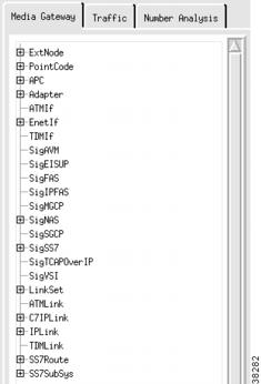
The CMM provides tabs you can use to navigate through the system, see Figure 3-3. You click on these tabs to add or change network components. The CMM contains the following tabs:
•
Media Gateway Controller Tab—Used to add components and provision component properties.
•
Traffic tab—Used to create customer-specific files, including trunk groups, trunks, and routing.
•
Number Analysis—Used to provision number analysis.
The left side of the screen displays a list of components that you select. The right panel of the screen displays fields in which you enter data. Click a component to select it. To see all components, click the + sign next to the component name to expand the component list.
Figure 3-3 Component List
Information Boxes
The top of the screen contains the information boxes shown in Figure 3-4.
Figure 3-4 Information Boxes

•
Remote host—The IP address of the machine that contains the active provisioning session.
•
Session name—The name of your session you entered in Step 6.
•
Manager station—The IP address or host name of the CMM server.
Status Messages
The bottom left portion of the CMM screen provides status messages when you perform an action. For example, after you start the CMM, the message "Cisco Media Gateway Controller Manager started" appears. After you click the Create button when creating an external node, the message "extnode set successful" appears.
Menu Bar
The CMM also provides a menu bar that remains constant throughout the provisioning session. Your choices depend on whether you are in read-only or read-write mode. The menu bar contains the following selections:
•
Session
•
View
•
Help
The Session menu contains the choices listed in Table 3-1.
Table 3-1 Session Menu Choices
Sync
Copies all configurations on the active1 Cisco MGC host machine to the standby Cisco MGC host (if you have a continuous-service configuration).
Read-only
Stop
Ends the current configuration session.
Read-write
Deploy
Ends the session and saves the current configuration as the active configuration. Copies the configuration to the standby Cisco MGC (if you have a continuous-service configuration).
Read-write
Commit
Ends the session and saves the current configuration as the active configuration.
Note
This command makes the current configuration active regardless of whether it is deployed on the active or standby Cisco MGC host in a continuous-service configuration.
Read-write
Exit
Stops any open provisioning session and exits the CMM.
Read-only and read-write
1 The active Cisco MGC in a continuous-service configuration is the machine that is processing calls. Do not confuse with the active provisioning session, which is located on the CMM host machine.

Note
The CMM saves your configuration each time you click the create, modify, set, or delete button. You can exit and return to the CMM later to modify this configuration before you commit or deploy it.
The View menu contains the View Next option, see Figure 3-5. Use this option to choose the number of data rows displayed in the CMM list boxes. For example, if you enter 10, the list boxes in the CMM display data 10 rows at a time. You can display a range of 1 through 999.
Figure 3-5 View Next Menu

The Help menu contains only software copyright and version information at this time.
Saving and Committing/Deploying the New Configuration
Your configuration is saved each time you click the create, modify, set, or delete button during your provisioning session.
To activate the provisioning session:
•
If you have a continuous-service configuration with two Cisco MGC hosts, choose Deploy from the Session menu. The configuration is saved on the active host and copied to the standby host. You must restart the standby server after reconfiguration to apply changes.
•
If you have a simplex configuration with one Cisco MGC host, choose Commit from the Session menu.
•
If have a continuous-service configuration and you are in read-only mode, choose Sync to copy the configuration from the active to standby host.

Note
In a continuous-service configuration, the XECfgParm.dat file on each machine must be configured properly. If you experience problems, verify the XECfgParm.dat files on both machines with Chapter 2, "Installing the Cisco Media Gateway Controller Software," in the Cisco Media Gateway Controller Software Release 7 Installation and Configuration Guide.
Exiting the CMM
You can exit the CMM at any time by performing one of these actions:
•
From the Session menu, choose Exit. Click Yes at the prompt.
•
From any tab, click Exit. Click Yes at the prompt.
•
Click the close box in the upper right corner of the CMM screen.

Note
The CMM screen closes without you receiving a prompt message.
Provisioning System Components
To provision your system, you first provision the system components. The following sections describe all components. To provision components, you must first log in to the CMM as described in the "CMM Provisioning Overview" section, and select the Media Gateway Controller tab. The components are listed and defined in "Planning for Provisioning."

Note
These components vary depending on which solution you are implementing. You will not use all components in a single configuration. For more information, see the solution-specific chapters in this guide.
Components are structured hierarchically, although the structure that appears on the CMM screen does not reflect their true hierarchy. You must provision parent components (for example, the point code component) before provisioning children components (for example, the linkset). Figure 3-6 shows the component relationship.
Figure 3-6 CMM Component Relationships

Entering MML Names and Descriptions
You must enter an MML name and a description for each component you provision. MML names must have the following characteristics:
•
As many as 20 alphanumeric characters, including hyphens
•
No space, underscore, or special characters
•
Must start with an alphabetic character
•
Must be lowercase

Note
To delete entered MML name or description text, you can click and drag to highlight the text to be changed; or you can press Shift and Backspace to delete the text to the left of the insertion point.
Descriptions can be as many as 128 characters and can include spaces and symbols. You should use descriptions that help identify the components or links that you are provisioning. For example, for an SS7 route that indicates the signaling path from the Cisco MGC to a switch through a linkset, you could create a description "SS7 Route to PSTN Switch A through Linkset 1".
Adding External Nodes
Use the external node component to add the following:
•
Any other Cisco MGCs in your network
•
Media gateways
•
Any other device in your network connected to the Cisco MGC
Note
Cisco SLTs perform MTP layer 2 processing only. Therefore, you do not need to add them as external nodes when provisioning.
For more information about external nodes, refer to the "Defining SS7 Network Addresses" section. To add an external node, perform the following steps:
Step 1
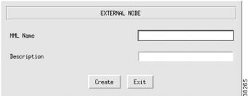
In the Media Gateway Controller tab, click ExtNode to display the External Node menu, see Figure 3-7.
Step 2
Enter the MML name.
Step 3
Enter the description.
Step 4
Click Create. The external node appears in the left display window under the ExtNode component.
Figure 3-7 Adding an External Node
Adding Point Codes
Use the point code components to add the OPCs or DPCs in your network. For more information about point codes, refer to the "Defining SS7 Network Addresses" section. To add a point code, perform the following steps:
Step 1
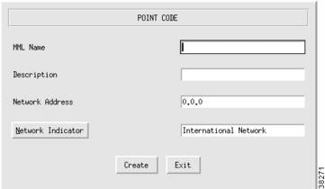
Click PointCode to display the Point Code menu, see Figure 3-8.
Step 2
Enter the MML name.
Step 3
Enter the description.

Note
The point code examples used in this document follow the ANSI SS7 point code format.
Step 4
Enter network address in dotted notation; for example, 147.26.1.
Step 5
Choose network indicator:
•
International network—Used if the node is an international gateway (default value).
•
Spare (for international use)—Used in countries where multiple carriers share point codes; in this case, networks are differentiated by this indicator.
•
National network—Used if the node routes calls through the national network.
•
Reserved (for national use)—Do not use.
Step 6
Click Create. The point code appears in the left display window under the PointCode component.
Figure 3-8 Adding a Point Code
Adding Adjacent Point Codes
Use the APC component to add the APCs in your network. For more information about adjacent point codes, refer to the "Defining SS7 Network Addresses" section. To add an APC, perform the following steps:
Step 1
Click APC to display the Adjacent Point Code menu, see Figure 3-9.
Step 2
Enter the MML name.
Step 3
Enter the description.
Step 4
Enter network address in dotted notation; for example, 147.26.1.
Step 5
Enter the network indicator:
•
International network—Used if the node is an international gateway.
•
Spare (for international use)—Used in countries where multiple carriers share point codes; in this case, networks are differentiated by this indicator.
•
National network—Used if the node routes calls through the national network.
•
Reserved (for national use). Do not use.
Step 6
Click Create. The APC appears in the left display window under the APC component.
Figure 3-9 Adding an APC

Adding Adapters (Cards)
Use the adapter component to add a card for each card in your Cisco MGC host. For more information about adapter cards, refer to the "Planning Network Cards for Media Gateway Communications" section. To add a card, perform the following steps:
Step 1
Click Adapter to display the Adapter menu, see Figure 3-10.
Step 2
Enter the MML name.
Step 3
Choose type:
•
ITK: T1 or E1 card—Used if the T1 or E1 carrying the signaling from the STP terminates at the Cisco MGC host (Cisco SS7 Dial Access Solution Release 2.0).

Note
The cards referred to as "ITK" are now manufactured by Digi International AG (formerly known as ITK).
•
V35: V.35 card—Used for V.35 connections into the Cisco MGC host.
•
EN: Ethernet interface card—Used for Ethernet connections into the Cisco MGC host from a Cisco SLT or gateway. For example, links from the Cisco SLTs terminate at the Ethernet cards in the Cisco MGC host.
•
ATM_NIC—ATM network interface card.
Step 4
Enter the description.
Step 5
Enter physical slot of card in the server. Value range: 0 through 16, depending on the host server configuration. The first slot is usually 0.
Step 6
Click Create. The card appears in the left display window under the Adapter component.
Figure 3-10 Adding an Adapter (Card)

Adding Ethernet Interfaces
Add an Ethernet interface for each Ethernet card you added. The Ethernet interface represents a physical network connection on the card. To add an Ethernet interface, perform the following steps:
Step 1
Click EnetIf to display the Ethernet Line Interface menu, see Figure 3-11.
Step 2
Click Ethernet Adapter to choose the Ethernet card for this interface.
Step 3
Enter the MML name.
Step 4
Enter the description.
Step 5
Click Create. The Ethernet interface appears in the left display window under the EnetIf component.
Figure 3-11 Adding an Ethernet Interface

Adding TDM Interfaces
Add a TDM interface for each T1/E1 or V.35 card in your server (refer to the "Adding Adapters (Cards)" section). The TDM interface represents a physical network connection on the card. To add a TDM interface for T1 or E1 cards, perform the following steps:
Adding TDM Interfaces for T1/E1 Cards
Step 1
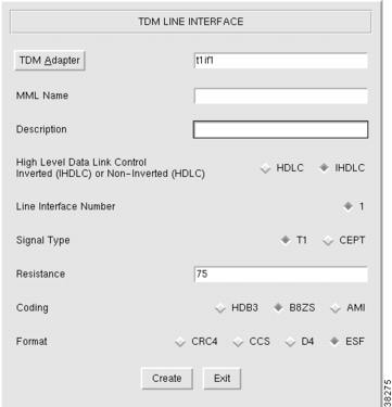
Click TDMIf to display the TDM Line Interface menu, see Figure 3-12.
Step 2
Click TDM Adapter to choose the T1/E1 card for this interface.
Step 3
Enter the MML name.
Step 4
Enter the description.
Step 5
Choose control:
•
HDLC—High-Level Data Link Control

Note
This is a bit-oriented synchronous data link layer protocol that specifies a data encapsulation method on synchronous serial links using frame characters and checksums. Most countries use this protocol.
•
IHDLC: Inverted High-level Data Link Control
Step 6
Verify the Line Interface Number default value of 1; you cannot change this value for T1/E1 cards.
Step 7
Choose signal type:
•
T1
•
CEPT
Step 8
Enter resistance:
•
75
•
120
Step 9
Choose coding:
•
HDB3
•
B8ZS
•
AMI
Step 10
Choose format:
•
CRC4
•
CCS
•
D4
•
ESF
Step 11
Click Create. The TDM interface appears in the left display window under the TDMIf component.
Figure 3-12 Adding a TDM Interface for T1/E1 Cards
Adding TDM Interfaces for V.35 Cards
To add a TDM interface for a V.35 card, perform the following steps:
Step 1
Click TDMIf to display the TDM Line Interface menu, see Figure 3-13.
Step 2
Click TDM Adapter to choose the V.35 card for this interface.
Step 3
Enter the MML name.
Step 4
Enter the description.
Step 5
Note that HDLC is the default value for control; you cannot change this value for V.35 cards.

Note
This is a bit-oriented synchronous data link layer protocol that specifies a data encapsulation method on synchronous serial links using frame characters and checksums. Most countries use this protocol.
Step 6
Choose the line interface number (1, 2, 3, or 4).
Step 7
Note that the signal type default value is V.35; you cannot change this value.
Step 8
Note that DTE is the default DTE/DCE value; you cannot change this value.
Step 9
Choose data rate:
•
48
•
56
•
64
Step 10
Note the default clock value of external; you cannot change this value.
Step 11
Click Create. The TDM interface appears in the left display window under the TDMIf component.
Figure 3-13 Adding a TDM Interface for V.35 Cards

Adding an SS7 Signaling Service
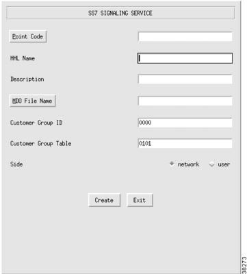
If you have a signaling service from the Cisco MGC to a PSTN switch, use the SigSS7 component to add it to your configuration. To add an SS7 signaling service, perform the following steps:
Step 1
Click SigSS7 to display the SS7 Signaling Service menu, see Figure 3-14.
Step 2
Click Point Code to select the destination point code (the point code of the PSTN switch) for this signaling service.
Step 3
Enter the MML name.
Step 4
Enter the description.
Step 5
Click MDO File Name to choose the protocol for this signaling service; for example, ANSISS7_STANDARD.
Step 6
Enter Customer Group ID (formerly VNETID). This value is used in number analysis.
Step 7
Enter Customer Group Table.
Step 8
Choose side (Q.931 call model side):
•
Network—The Cisco MGC side of the link
•
User—The SS7 side of the link
Step 9
Click Create. The SS7 signaling service appears in the left display window under the SigSS7 component.
Figure 3-14 Adding an SS7 Signaling Service
Changing SS7 Signaling Service Properties
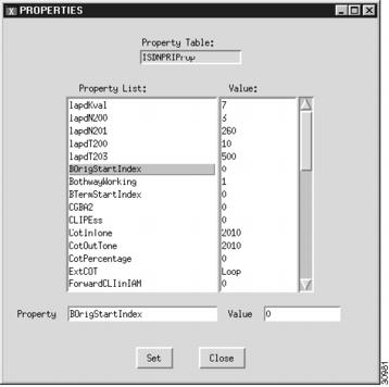
You can change the properties of the SS7 signaling services you have created. These properties apply to all SS7 signaling services you create. You do not have to change the default properties. For a list of signaling service properties, default values, and descriptions, refer to "Planning for Provisioning."
After you create a signaling service, the Properties button appears on the right screen panel. To change signaling service properties, perform the following steps:
Step 1
Click Properties to display the list of properties, see Figure 3-15.
Step 2
Click the property you want to change.
Step 3
In the value field, overwrite the property value with the desired value.
Step 4
Click Set. The property set message appears at the bottom left of the CMM screen.
Step 5
Click Close when you are finished.

Note
You cannot modify properties until after you have created the signaling service.
Figure 3-15 Changing SS7 Signaling Service Properties

Adding a NAS Signaling Service
You must add a NAS signaling service for each NAS you created in your network under the ExtNode component. To add a NAS signaling service, perform the following steps:
Step 1
Click SigNAS to display the NAS Signaling Service menu, see Figure 3-16.
Step 2
Click External Node to choose the access server for this signaling service.
Step 3
Enter the MML name.
Step 4
Enter the description.
Step 5
Click MDO File Name to choose the protocol for this signaling service. Currently, only BELL_1268_C3 is supported.
Step 6
Enter Customer Group ID (formerly VNETID).
Step 7
Enter Customer Group Table.
Step 8
Choose side (Q.931 call model side):
•
Network—The Cisco MGC side of the link.
•
User—The NAS side of the link.
Step 9
Click Create. The NAS signaling service appears in the left display window under the SigNAS component.

Note
If you are configuring a redundant system, you must define two redundant link manager links between each MGC and MGW. Each redundant link manager group must be associated with a different port number and a different NASPATH, but the same EXTNODE.
Figure 3-16 Adding a NAS Signaling Service

Changing NAS Signaling Service Properties
You can change the properties of the NAS signaling services you have created. These properties apply to all NAS signaling services you create. You do not have to change the default properties. For a list of signaling service properties, default values, and descriptions, refer to "Planning for Provisioning."
After you create a NAS signaling service, the Properties button appears on the right screen panel. To change signaling service properties, perform the following steps:
Step 1
Click Properties to display the list of properties, see Figure 3-17.
Step 2
Click the property you want to change.
Step 3
In the Value field, overwrite the property value with the desired value.
Step 4
Click Set. The property set message appears at the bottom left of the CMM screen.
Step 5
Click Close when you are finished.

Note
You cannot modify properties until after you have created the NAS signaling service.
Figure 3-17 Changing NAS Signaling Service Properties
Adding an IPFAS Signaling Service
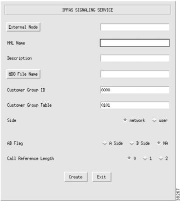
For information about an IPFAS signaling service, refer to the "Planning for the Media Gateway Signaling Service" section. To add an IPFAS signaling service, perform the following steps:
Step 1
Click SigIPFAS to display the IPFAS Signaling Service menu, see Figure 3-18.
Step 2
Click External Node to choose the Cisco MGC for this signaling service.
Step 3
Enter the MML name.
Step 4
Enter the description.
Step 5
Click MDO File Name to choose the protocol for this signaling service; for example, ATT_41459.
Step 6
Enter Customer Group ID (formerly VNETID).
Step 7
Enter Customer Group Table.
Step 8
Choose side (Q.931 call model side):
•
Network—The Cisco MGC side of the link
•
User—The Redundant Link Manager (RLM) side of the link
Step 9
Choose A/B flag:
•
A side
•
B side
•
NA
Step 10
Choose call reference length:
•
0
•
1
•
2
Step 11
Click Create. The IPFAS signaling service appears in the left display window under the SigIPFAS component.
Figure 3-18 Adding an IPFAS Signaling Service
Changing IPFAS Signaling Service Properties
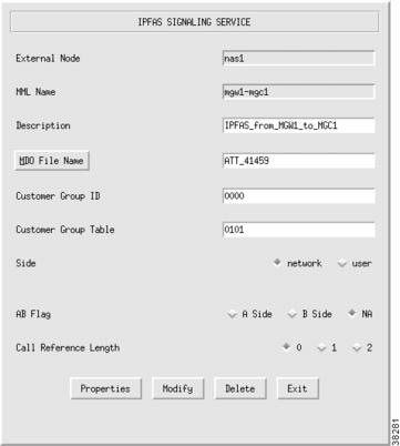
You can change the properties of the IPFAS signaling services you have created. These properties apply to all IPFAS signaling services you create. You do not have to change the default properties. For a list of signaling service properties, default values, and descriptions, refer to "Planning for Provisioning."
After you create an IPFAS signaling service, the Properties button appears on the right screen panel. To change signaling service properties, perform the following steps:
Step 1
Click Properties to display the list of properties, see Figure 3-19.
Step 2
Click the property you want to change.
Step 3
In the value field, overwrite the property value with the desired value.
Step 4
Click Set. The property set message appears at the bottom left of the CMM screen.
Step 5
Click Close when you are finished.

Note
You cannot modify properties until after you have created the IPFAS signaling service.
Figure 3-19 Changing IPFAS SIgnaling Service Properties
Adding a TCAPOverIP Signaling Service
You must add a TCAPOverIP signaling service if you are provisioning an announcement server in your network. To add a TCAPOverIP signaling service, perform the following steps:
Step 1
Click SigTCAPOverIP to display the TCAP Over IP Signaling Service menu, see Figure 3-20.
Step 2
Click External Node to choose the media gateway for this signaling service.
Step 3
Enter the MML name.
Step 4
Enter the description.
Step 5
Click Create. The TCAPOverIP signaling service appears in the left display window under the SigTCAPOverIP component.
Figure 3-20 Adding a TCAPOverIP Signaling Service

Changing TCAPOverIP Signaling Service Properties
You can change the properties of the TCAPOverIP signaling services you have created. These properties apply to all TCAPOverIP signaling services you create. You do not have to change the default properties. For a list of signaling service properties, default values, and descriptions, refer to "Planning for Provisioning."
After you create a TCAPOverIP signaling service, the Properties button appears on the right screen panel. To change signaling service properties, perform the following steps:
Step 1
Click Properties to display the list of properties.
Step 2
Click the property you want to change.
Step 3
In the value field, overwrite the property value with the desired value.
Step 4
Click Set. The property set message appears at the bottom left of the CMM screen.
Step 5
Click Close when you are finished.

Note
You cannot modify properties until after you have created the TCAPOverIP signaling service.
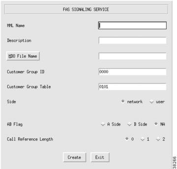
Adding a FAS Signaling Service
For information about a FAS signaling service, refer to the "Planning for the Media Gateway Signaling Service" section. To add a FAS signaling service, perform the following steps:
Step 1
Click SigFAS to display the FAS Signaling Service menu, see Figure 3-21.
Step 2
Enter the MML name.
Step 3
Enter the description.
Step 4
Click MDO File Name to choose the protocol for this signaling service; for example, ATT_41459.
Step 5
Enter Customer Group ID (formerly VNETID).
Step 6
Enter Customer Group Table.
Step 7
Choose side (Q.931 call model side):
•
Network—The Cisco MGC side of the link
•
User—The RLM side of the link
Step 8
Choose A/B flag:
•
A side
•
B side
•
NA
Step 9
Choose call reference length:
•
0
•
1
•
2
Step 10
Click Create. The FAS signaling service appears in the left display window under the SigFAS component.
Figure 3-21 Adding a FAS Signaling Service
Changing FAS Signaling Service Properties
You can change the properties of the FAS signaling services you have created. These properties apply to all FAS signaling services you create. You do not have to change the default properties. For a list of signaling service properties, default values, and descriptions, refer to "Planning for Provisioning."
After you create a FAS signaling service, the Properties button appears on the right screen panel. To change signaling service properties, perform the following steps:
Step 1
Click Properties to display the list of properties.
Step 2
Click the property you want to change.
Step 3
In the value field, overwrite the property value with the desired value.
Step 4
Click Set. The property set message appears at the bottom left of the CMM screen.
Step 5
Click Close when you are finished.

Note
You cannot modify properties until after you have created the FAS signaling service.
Adding an EISUP Signaling Service
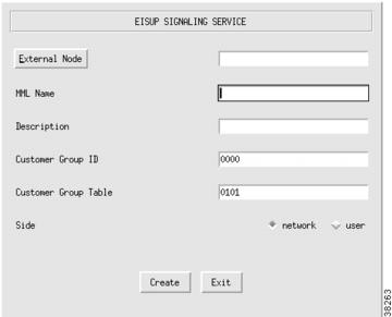
Add an EISUP signaling service if you have more than one Cisco MGC in your network. The Cisco MGCs use EISUP to communicate with each other. To add an EISUP signaling service, perform the following steps:
Step 1
Click SigEISUP to display the EISUP Signaling Service menu, see Figure 3-22.
Step 2
Click External Node to choose the other Cisco MGC.
Step 3
Enter the MML name.
Step 4
Enter the description.
Step 5
Enter Customer Group ID (formerly VNETID).
Step 6
Enter Customer Group Table. This is used for DPNSS feature transparency.
Step 7
Choose side (Q.931 call model side):
•
Network—The Cisco MGC side of the link
•
User—The PSTN side of the link
Step 8
Click Create. The EISUP signaling service appears in the left display window under the SigEISUP component.

Note
To ensure correct failover operation in a configuration with two local MGCs (one active and one standby) and a remote MGC, you need a minimum of two EISUP links from the remote VSC to each MGC redundant pair.
Figure 3-22 Adding an EISUP Signaling Service
Changing EISUP Signaling Service Properties
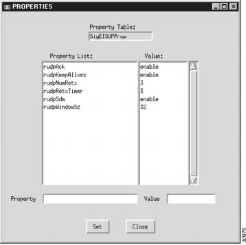
You can change the properties of the EISUP signaling services you have created. These properties apply to all EISUP signaling services you create. You do not have to change the default properties. For a list of signaling service properties, default values, and descriptions, refer to "Planning for Provisioning."
After you create an EISUP signaling service, the Properties button appears on the right screen panel. To change signaling service properties, perform the following steps:
Step 1
Click Properties to display the list of properties, see Figure 3-23.
Step 2
Click the property you want to change.
Step 3
In the Value field, overwrite the property value with the desired value.
Step 4
Click Set. The property set message appears at the bottom left of the CMM screen.
Step 5
Click Close when you are finished.

Note
You cannot modify properties until after you have created the EISUP signaling service.
Figure 3-23 Changing EISUP Signaling Service Properties
Adding Linksets
Linksets are groups of links that connect two components. Linksets can consist of the following:
•
EISUP links between two Cisco MGCs (OPC to OPC)
•
Links from the Cisco MGC (OPC) to an adjacent STP (APC)
•
Links from the Cisco MGC (OPC) to a destination (an APC acting as a DPC, if there is no STP)
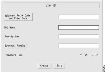
For more information about linksets, refer to the "Defining Linksets" section. To add a linkset, perform the following steps:
Step 1
Click LinkSet to display the Link Set menu, see Figure 3-24.
Step 2
Click Adjacent Point Code and Point Code and select the APC component for this linkset.
Step 3
Enter the MML name.
Step 4
Enter the description.
Step 5
Choose a protocol family:
•
SS7-ANSI
•
SS7-China
•
SS7-ITU
•
SS7-Japan
•
SS7-UK
Step 6
Choose the transport type:
•
TDM—Used only if the signaling link terminates in the Cisco MGC, as in the Cisco SS7 Dial Access Solution Release 2.0
•
IP—Used for all other links
Step 7
Click Create. The linkset appears in the left display window under the LinkSet component.
Figure 3-24 Adding a Linkset
Changing Linkset Properties
You can change the properties of the linksets you have created. These properties include message and timer values, and apply to all linksets you create. You do not have to change the default properties. For a list of linkset properties, default values, and descriptions, refer to "Planning for Provisioning".
After you create a linkset, the Properties button appears on the right screen panel. To change linkset properties, perform the following steps:
Step 1
Click Properties to display the list of properties.
Step 2
Click the property you want to change.
Step 3
In the value field, overwrite the property value with the desired value.
Step 4
Click Set. The property set message appears at the bottom left of the CMM screen.
Step 5
Click Close when you are finished.

Note
You cannot modify properties until after you have created the linkset.
Adding C7 IP Links
You must add a C7 IP link for each physical SS7 link that is connected to the SS7 network through the Cisco SLT. These links correspond to the linksets you created in the "Adding Linksets" section. For more information about C7 IP links, refer to the "Planning A-Links Through Cisco SLTs" section. To add a linkset, perform the following steps:
Step 1
Click C7IPLink to display the C7 IP Link menu, see Figure 3-25.
Step 2
Click Link Set and choose the linkset for this link.
Step 3
Enter the MML name.
Step 4
Enter the description.
Step 5
Click Enet Line Interface to choose the Ethernet interface for this link.
Step 6
Enter a port number. This is the UDP port on the Cisco MGC. You can use any unused UDP port number, but you should not use 1 through 1024 (these are reserved for other applications).
Step 7
Choose the priority. Value range: 1 through 4. 1 is the highest priority.

Note
To enable loadsharing, use the same priority (1) for each C7 IP link. If there is a failure, traffic is routed equally over both links.
Step 8
Enter the IP address of the Cisco SLT in the peer address field.
Step 9
Enter 32767 in the peer port field. This is a dummy value and is not used by the software.

Note
The actual peer port value is found in the *.stPort field in the XECfgParm.dat file you set up during your initial system configuration. See the Cisco Media Gateway Controller Software Release 7 Installation and Configuration Guide for more information.
Step 10
Choose IP address of the Cisco MGC:
•
Addr1
•
Addr2
•
Addr3
•
Addr4

Note
The numbered address for this value is found in the XECfgParm.dat file you set up during your initial system configuration. Refer to Cisco Media Gateway Controller Software Release 7 Installation and Configuration Guide for more information.
Step 11
Enter the time slot. This is the physical port on the Cisco SLT.

Note
The time slot number must be unique per link on a particular Cisco SLT. For example, if you have a 2T WAN interface card (WIC) in slot 0 of the Cisco SLT, you can use time slot values 0 or 1 for the first link you configure. The second link on that WIC uses the remaining value.
Step 12
Enter 1 in the link code field. This is the signaling link code (SLC) for the line between the Cisco SLT and the STP. The SLC can be any integer from 0 through 15.
Step 13
Click Create. The C7 IP link appears in the left display window under the C7IPLink component.
Figure 3-25 Adding a C7 IP Link

Adding IP Links
You need to add an IP link from each NAS to the Cisco MGC. For information about IP links, refer to the "Planning IP Links" section. To add an IP link, perform the following steps:
Step 1
Click IPLink to display the IP Link menu, see Figure 3-26.
Step 2
Click IP Signaling Services and choose the signaling service for this link.
Step 3
Enter the MML name.
Step 4
Enter the description.
Step 5
Click Enet Line Interface to choose the Ethernet interface for this link.
Step 6
Enter a port number. This is the UDP port on the Cisco MGC. You can use any unused UDP port number, but you should not use 1 through 1024 (these are reserved for other applications).
Step 7
Choose priority. Value range: 1 through 4. 1 is the highest priority.
Step 8
Enter the IP address of the NAS in the peer address field.
Step 9
Enter the port number in the peer port field. This is the port on the NAS and the value is
port number + 1, where port number is the RLM port created on the NAS. By default, 3000 is the port number for RLM and 3001 is the port number for ISDN.Step 10
Choose the IP address of the Cisco MGC:
•
Addr1
•
Addr2
•
Addr3
•
Addr4

Note
The numbered address for this value is found in the XECfgParm.dat file you set up during your initial system configuration. Refer to the Cisco Media Gateway Controller Software Release 7 Software Installation and Configuration Guide for more information.
Step 11
Enter values in the signal slot/port fields.
Step 12
Click Create. The IP link appears in the left display window under the IPLink component.
Figure 3-26 Adding an IP Link

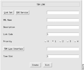
Adding TDM Links
You must add a TDM link for each path from the TDM to the Cisco MGC. You have one link for each T1/E1 card in the Cisco MGC host, which is associated with a TDM interface. These links are contained within the linksets you previously created. (Refer to the "Adding Linksets" section.) For information about TDM links, refer to the "Planning A-Links to Signaling Points" section. To add a TDM link, perform the following steps:
Step 1
Click TDMLink to display the TDM Link menu, see Figure 3-27.
Step 2
Click Linkset and choose the linkset for this link.
Step 3
Enter the MML name.
Step 4
Enter the description.
Step 5
Enter the link code.
Step 6
Choose the priority. Value range: 1 through 4. 1 is the highest priority.
Step 7
Click TDM Line Interface to choose the line interface for this link.
Step 8
Enter a time slot number in the time slot field. This is the channel on the physical line from the TDM to the Cisco MGC. Value range: 1 through 32.
Step 9
Click Create. The TDM link appears in the left display window under the TDMLink component.
Figure 3-27 Adding a TDM Link
Adding SS7 Routes
You must add an SS7 route for each signaling path from the Cisco MGC to the PSTN switch through the linksets you have created to the STPs. You should create two routes to the PSTN switch, with each route passing through a different STP of a mated pair. For more information about SS7 routes, refer to the "Defining SS7 Routes" section. To add an SS7 route, perform the following steps:
Step 1
Click SS7Route to display the SS7 Route menu, see Figure 3-28.
Step 2
Enter the MML name.
Step 3
Enter the description.
Step 4
Click Signal Destination or Adjacent Point Code and choose the DPC of the PSTN switch.
Step 5
Click Link Set to choose the linkset for this route.
Step 6
Click Originating Point Code to choose the origination point code for this route.
Step 7
Click Create. The SS7 route appears in the left display window under the SS7Route component.
Figure 3-28 Adding an SS7 Route

Adding an SS7 Subsystem
SS7 subsystems are used by the MGC software to identify a pair of mated STPs connected by C-links. The SS7 subsystem is also used to connect an STP to an SCP database for AIN queries. In this case, there is no mated STP.
For information about an SS7 subsystem, refer to the "Defining SS7 Subsystems" section. To add an SS7 subsystem, perform the following steps:
Step 1
Click SS7SubSys to display the SS7 Sub System menu, see Figure 3-29.
Step 2
Enter the MML name.
Step 3
Enter the description.
Step 4
If identifying mated STPs, click Adjacent Point Code to choose the APC of the first STP.
Step 5
If using the subsystem for AIN queries, click TCAPOverIP Service to choose the service you set up in the "Adding a TCAPOverIP Signaling Service" section.
Step 6
If identifying mated STPs, click Mated Adjacent Point Code to choose the APC of the second STP. If using the subsystem for AIN queries, choose None.
Step 7
Choose Protocol Family:
•
SS7-ANSI—Use when identifying mated STPs or using the subsystem for AIN queries.
•
SS7-China—Use when identifying mated STPs only.
•
SS7-ITU—Use when identifying mated STPs or using the subsystem for AIN queries.
•
SS7-Japan—Use when identifying mated STPs only.
•
SS7-UK—Use when identifying mated STPs only.

Note
If you have multiple linksets to an STP that use different protocol families, you must also have multiple SS7 subsystems—one for each linkset that uses a certain protocol.
Step 8
Choose the priority. Value range: 1 through 4. 1 is the highest priority.

Tip
When you are identifying mated STPs, the priority for the SS7 subsystem should always be lower than the priority for the C7 IP links between the Cisco MGC and the STPs (that you provisioned using the "Adding C7 IP Links" section). You do not want signaling traffic on the C-links between the STPs; these are used only if links go down. If the priority for the C-links (SS7 subsystem) between the STPs is higher than or equal to the priority for the C7 IP links, the Cisco MGC routes signaling traffic over those links. If you set the SS7 subsystem priority lower than the priority for the C7 IP links, the Cisco MGC routes traffic over the C-links between the STPs only if the links with a higher priority are not available.
Step 9
Enter the Subsystem Number (SSN). The SSN indicates the application entity that the message must reach at the final destination node (or SCP database). The Cisco MGC software includes the SSN value in queries sent to the SCP, and the SCP includes the same value in its return responses.

Note
When identifying mated STPs, enter 0, because this field is not used.
The following SSN values are defined in the ANSI SCCP Spec. T1.112:
•
0—Not used.
•
1—SCCP Management.
•
2—Telephone User Part (TUP).
•
3—ISDN user Part.
•
4—OA&M.
•
255—Not used; reserved for future expansion.
In the United States Public Switched Telephone Network (PSTN), the following conventions are followed:
•
254—800 services.
•
251—CLASS.
•
250—AIN. The Cisco MGC software uses AIN protocol for LNP queries, so we recommend this value.
Step 10
Enter the STP-SCP index field. When you are identifying mated STPs, the default is 0. When you are identifying AIN services, you are defining the index for the STP pair that is used by the TCAP subsystem to process TCAP requests.
Step 11
Choose transport protocol if you are identifying AIN services:
•
SCCP
•
TCPIP

Note
Not used when you are identifying mated STPs.
Step 12
Click Create. The SS7 subsystem appears in the left display window under the SS7Subsys component.
Figure 3-29 Adding an SS7 Subsystem

Modifying System Components
Modify components by selecting the component in the left side of the screen, see Figure 3-3. On the right side of the screen, modify the desired fields and click Modify, see Figure 3-19. A set successful message appears in the lower left of the main CMM screen.

Note
You cannot modify some fields in a component that are used by other components in the system. For example, you cannot change a card type, because the card type field is used in the interface component. Fields that you cannot modify appear gray, and you cannot enter information in them.

Tip
You cannot modify MML names once you have created a component. You must delete the component and enter a new component with a different name.
Deleting System Components
To delete components, select the component and click Delete in the right screen panel. A dialog box asks you to confirm any deletions, and a message appears in the lower left of the main CMM screen telling you the component was deleted.

Note
You cannot delete a component that is a parent of another component. For example, you cannot delete a linkset that contains links. You receive an error message when you try to delete a parent component.
Provisioning Trunk Groups
Trunks carry bearer traffic from destination switches to media gateways (MGWs).
For solutions that use switched trunks, you must provision trunk groups and configure trunk routing. For switched trunks, the Cisco MGC provides addressing information to the MGWs, such as the NASs. You need to create trunk groups, routes, and route groups for switched trunks.
A trunk group is a group of trunks. The Cisco MGC can route to different trunks within a trunk group. You create TDM trunk groups for connections between the destination switch and the MGW. You create IP trunk groups for EISUP connections between two or more MGWs.

Note
If you are provisioning switched trunks, you must create trunk groups before creating any trunks. If you are provisioning nailed trunks, trunk groups are not used and trunks are created before routes.
Creating the Trunk Group File
To add the trunk groups, first create a trunk group file, by performing the following steps:
Step 1
Click the Traffic tab.
Step 2
Click Trunk Group.
Step 3
Enter the filename for the trunk group.
Step 4
Click Create New File. The trunk group file appears in the left display window under the TrunkGroup component.
Step 5
After creating the file, click the + sign next to the filename on the left side of the screen. The Trunk Group component appears.
Adding the Trunk Groups
To add a trunk group, perform the following steps:
Step 1
In the Trunk Group List screen, click New.
Step 2
Enter the trunk group number. You can choose any four-digit number.
Step 3
Enter the CLLI. This is an 11-digit alphanumeric code managed by Telcordia that identifies the originating trunk group to the Cisco MGC. Use the code provided by your carrier.
Step 4
Click Signaling Service. This corresponds to the signaling service you created when you set up your configuration in the Telephony Controller tab.
Step 5
Click Trunk Group Type and select the type. You can choose one of the following types:
•
TDM_GEN
•
TDM_ISUP
•
TDM_CAS
•
TDM_TUP
•
TDM_DPNSS
•
TDM_PRI
•
TDM_BTNUP
•
IP
Step 6
Choose Yes or No for queuing. This indicates if the Cisco MGC uses queuing on the trunk during call processing.
Step 7
Enter the Ring No Answer value that is used in conjunction with queuing. You can choose one of the following values:
•
0—If you are not using queuing, the Cisco MGC rejects the call.
•
1—If you are using queuing, the Cisco MGC queues the call.
Step 8
Choose how the Cisco MGC will handle glare (simultaneous circuit seizure) by the Cisco MGC and the switch. You can choose one of the following values:
•
Always—The Cisco MGC always yields to the switch when seizing a trunk.
•
Even/Odd—The switch with the highest point code controls even circuits.
•
Never—The Cisco MGC never yields to the switch when seizing a trunk.
Step 9
Enter the COT percentage (0 to 100). This determines the percentage of calls on a trunk that are for continuity tests (SS7 only).
Step 10
Choose the Select Sequence used to determine trunk selection sequence. You can choose one of the following:
•
LIDL—Least idle trunk
•
MIDL—Most idle trunk
•
ASC—Ascending trunk order
•
DESC—Descending trunk order
•
RDM—Random trunk order
•
EDESC—Even descending, then odd descending order
•
ODESC—Odd descending, then even descending order
•
EASC—Even ascending, then odd ascending order
•
OASC—Odd ascending, then even ascending order
Step 11
Choose Yes or No for VSF priority. This is a PBX feature for storing and forwarding of voice messages.
Step 12
Choose Yes or No for Satellite. This indicates if a satellite link is used with the trunk group.
Step 13
Click Properties to set trunk group properties. The trunk group properties screen appears. You can set the following properties:
•
Numbering Plan Area—Identifies the three-digit NPA code for the incoming trunk group.
•
Carrier ID—Identifies the presubscribed carrier ID for the trunk group.
•
Screen Fail Action—Indicates the action to be taken on traffic if screening cannot be supported. Typically set to 0 (continue traffic handling).
•
Customer Group ID—A customer-specific alphanumeric field. This is a required field.
•
B Originating Start Index—Identifies the starting node for originating number analysis. Typically set to 1.
•
B Terminating Start Index—Identifies the starting node for terminating number analysis. Typically set to 2.
•
Compression type—Identifies compression type for VoIP solutions. Typically set to 1 (mu-law) for North America.
•
Echo Cancellor Required—Indicates if echo cancellation is required. Typically set to 0 (no echo cancellor required).
Step 14
Click Set. The Properties Trunk Group screen closes.
Step 15
In the Trunk Group screen, click Set.
Processing the Trunk Group File
After you add the trunk groups, you must process the trunk group file. To process the trunk group file, perform the following steps:
Step 1
Under the trunk filename, select the TKGFile component.
Step 2
Enter the filename.
Step 3
Enter your user ID and password. You are the only user allowed to modify the file.
Step 4
Click Set.
The system opens an FTP session to the Cisco MGC host and copies the file. In addition, SNMP sets the filename in the MIB and the file is post-processed.

Note
Only one filename can be set in the MIB. If a new filename is set through using SNMP, the old name is overwritten.

Tip
If you receive an error message that the file cannot be processed, your SNMP session might not be running. The SNMP session times out after 30 minutes of inactivity. Exit the CMM and restart it before trying to process the file.
Modifying Trunk Groups
To modify a trunk group, perform the following steps:
Step 1
In the left side of the screen, click the + sign next to the filename of the trunk group file.
Step 2
Click TrunkGroup. The Trunk Group List appears on the right side of the screen.
Step 3
Select the trunk group from the list and click Modify. The trunk group screen appears.
Step 4
Make any desired changes in the Trunk Group screen and click Set. A screen appears that asks you to confirm the modification.
Step 5
Click Yes to modify the trunk group.
Deleting Trunk Groups
To delete a trunk group, perform the following steps:
Step 1
In the left side of the screen, click the + sign next to the filename of the trunk group file.
Step 2
Click TrunkGroup. The Trunk Group List appears on the right side of the screen.
Step 3
Select the trunk group from the list and click Delete. A screen appears that asks you to confirm the deletion.
Step 4
Click Yes to delete the trunk group.

CautionDeleting a trunk group deletes all trunks in that trunk group.
Adding Trunks
You must add trunks for each connection between the media gateway and a destination switch. For the Cisco SS7 Interconnect for Access Servers Solution and the Cisco SS7 Interconnect for Voice Gateways Solution, these trunks are nailed. With nailed trunks, the Cisco MGC does not perform switching of trunks.
In the Cisco Packet Tandem Solution, the Cisco MGC provides addressing information to the media gateways. The Cisco MGC performs switching of trunks, using trunk groups, routes, and route groups.

Note
You must create trunk groups before creating any trunks when you are provisioning switched trunks.
Creating the Trunk File
To add trunks using the Traffic tab in the CMM, first create the trunk file that will be populated with your data. To create a trunk file, perform the following steps:
Step 1
Click the Traffic tab.
Step 2
Click Trunks. The Create Trunks File Name screen appears.
Step 3
Click Trunk Type and choose Nailed or Switched.

Note
You can have only one trunk file (Nailed or Switched) at one time.
Step 4
Enter the filename and click Create New File. The trunk file appears in the left display window under the Trunks component.

Note
You can name the trunk file with any extension except .old (reserved for use by the CMM software). In this documentation, .txt is used.
After you set the filename, the filename and BCFile components appear under the Trunks component in the left screen panel. Click the + sign next to the filename to display the Nailed or Switched component.
Adding Nailed Trunks
To add an individual nailed trunk, perform the following steps:
Step 1
Under the trunk filename component you created, click Nailed.
Step 2
The Nailed Bearer list appears and is empty. Click New.
Step 3
Enter the trunk ID (a three-digit identifier).
Step 4
Click Source Signaling Service and select the appropriate SS7 signaling service.
Step 5
Select Fixed for the Source Span.
Step 6
Enter ffff for the Source Span ID.
Step 7
Enter the Source Time Slot/CIC. This identifies the time slot on the T1 at the destination (PSTN switch).
Step 8
Click Destination Signaling Service and choose the gateway signaling service.
Step 9
Select Fixed for the Destination Span. (This is the destination span type.)
Step 10
Enter the Destination Span ID. This value identifies the appropriate T1 or E1 line and T1 or E1 controller on the gateway. For example, it is the nfas_int value that is set in IOS on the NAS.
Step 11
Enter the Destination Time Slot/CIC field. This identifies the time slot on the T1 that terminates at the gateway.
Step 12
Select the line type:
•
T1
•
E1
Step 13
Enter the number of trunks in the multiple trunks field. For T1, you can enter 1 through 24. For E1, you can enter 1 through 31. The system automatically increments the trunk ID, source time slot/CIC, and the destination time slot/CIC.
Step 14
Click Set. A message in the lower left of the main CMM screen shows how many trunks you created.
Adding Switched Trunks
To add the individual switched trunks, you must first create Trunk Groups. Refer to the "Provisioning Trunk Groups" section. After you have created the Trunk Groups, perform the following steps to add a switched trunk:
Step 1
Under the trunk filename component you created, click Switched.
Step 2
The Switched Trunk Group List for All Trunk Groups appears, and is empty. Click New.
Step 3
Enter the trunk group number. This is the 4-digit number of the group you added in "Adding the Trunk Groups" section.
Step 4
Enter the trunk group member number.
Step 5
Select Increment or Fixed for the Span.
Step 6
Enter the Source Span ID. For most trunks, the value is ffff.
Step 7
Enter the CIC/Time Slot.
Step 8
Click External Node and choose the external node connected to these trunks.
Step 9
For End Point, enter the following values:
•
Interface—The interface on the media gateway. For example, on a Cisco MGX8260, this value could be DS-1-4, for the PRI card and slot on the gateway.
•
TS (time slot)—The time slot on the interface at the gateway.
•
Domain—The domain name you configured on the media gateway. However, in the Cisco SS7-PRI Gateway Solution, this name is not configured on the media gateway and you can enter any value.
Step 10
Select the line type:
•
T1
•
E1
Step 11
Enter the number of trunks in the multiple trunks field. For T1, you can enter 1 through 24. For E1, you can enter 1 through 31. The system automatically increments the trunk group member number, CIC/time slot, and time slot in the end point field.
Step 12
Click Set.
Processing the Trunk File
After you add the trunks, you must process the trunk file. To process the trunk file, perform the following steps:
Step 1
Under the trunk filename, select the BCFile component.
Step 2
Enter the filename.
Step 3
Enter your user ID and password. You are the only user allowed to modify the file.
Step 4
Click Set.
The system opens a File Transfer Protocol (FTP) session to the Cisco MGC host and copies the file. In addition, Simple Network Management Protocol (SNMP) sets the filename in the Management Information Base (MIB), and the file is post-processed.

Note
Only one filename can be set in the MIB. If a new filename is set using SNMP, the old name is overwritten.

Tip
If you receive an error message that the file cannot be processed, your SNMP session might not be running. The SNMP session times out after 30 minutes of inactivity. Exit the CMM and restart it before trying to process the file.
Modifying Trunks
To modify trunks, in the left side of the screen, select the name of the trunk filename you created in the "Creating the Trunk File" section. The right side of the screen displays the Nailed Bearer List or the Switched Bearer List.
To modify a trunk, perform the following steps:
Step 1
Select the trunk from the list and click Modify.
Step 2
The system prompts you with a screen showing the changes you are requesting and asks you to confirm the modification. Click Yes to modify the trunk.
Deleting Trunks
To delete trunks, in the left side of the screen, select the name of the trunk filename you created in the "Creating the Trunk File" section. The right side of the screen displays the Nailed Bearer List.
To delete a trunk, perform the following steps:
Step 1
Select the trunk from the list and click Delete.
Step 2
A dialog box displays the line you want to delete and asks you to confirm the deletion. Click Yes to delete the trunk.
Retrieving Trunk Files
Although the CMM allows you to use only one trunk file at a time, you can retrieve trunk files you previously created. To retrieve a trunk file, perform the following steps:
Step 1
Click the Trunks component.
Step 2
In the lower half of the screen, enter the filename of the file you want to retrieve.
Step 3
Enter the user name and password you gave the file when you created it.
Step 4
Click Get Existing.

Note
Get Existing retrieves the existing active configuration file from the MGC into the CMM file specified.
Provisioning Routes and Route Groups
You provision routes and route groups that are used by the Cisco MGC to direct traffic. Routes are different paths to the same destination, and route groups are user-defined sets of routes.
Creating the Routing File
To create a routing file, perform the following steps:
Step 1
Click the Traffic tab.
Step 2
Click Routing.
Step 3
Enter the routing filename.
Step 4
Click Create New File. After creating the file, click the + sign next to the filename on the left side of the screen. The Routes and Route Groups components appear.
Adding Routes
To add a route, perform the following steps:
Step 1
Click the Routes component in the left side of the screen. The Route List appears.
Step 2
Click New. The Routes screen appears.
Step 3
Enter the route name.
Step 4
Click Trunk Group Number to display the available trunk groups.
Step 5
Choose the trunk group number and click Select.
Step 6
Click Set. The Route List screen appears with the route name you just created and the associated trunk group.
Adding Route Groups
After adding routes, you add a route group that contains the routes. A route group contains different routes to the same destination that are located on physically separate paths. Therefore, if one route is unavailable, the Cisco MGC uses any other routes in the route group to reach the destination (for example, the PSTN switch).
To add a route group, perform the following steps:
Step 1
Click the RouteGroups component in the left side of the screen. The Route Group list appears.
Step 2
Click New. The Route Group screen appears.
Step 3
Enter the route group name.
Step 4
Enter the carrier ID.
Step 5
In the Available Routes screen, select the route and click Add Route. The route you selected appears in the Associated Routes screen.
Step 6
After you add the routes you want, in the Associated Routes screen, click Set. The route group list screen appears with the route group you just added.
Processing the Routing File
After you add the trunks, you must process the routing file. To process a routing file, perform the following steps:
Step 1
Under your route, select RoutingFile.
Step 2
Enter the filename in the filename field.
Step 3
Enter your user ID and password.
Step 4
Click Set. The system opens an FTP session to the Cisco MGC host and copies the file. In addition, SNMP sets the filename in the MIB and the file is post-processed.

Note
Only one filename can be set in the MIB. If a new filename is set through using SNMP, the old name is overwritten.

Tip
If you receive an error message indicating that the file cannot be processed, your SNMP session might not be running. The SNMP session times out after 30 minutes of inactivity. Exit the CMM and restart it before trying to process the file.
 Feedback