Cisco Catalyst 9800 Wireless Controller for Cloud on Microsoft Azure Deployment Guide
Available Languages
Cisco Catalyst 9800 Wireless Controller for Cloud on Microsoft Azure Deployment Guide
Table of Contents
Integration with Azure Marketplace
Section 0: Azure Deployment Workflow
Section 1: Create Resource Group
Section 2: Create Azure Virtual Network
Section 3: Create Network Security Group (for Azure Virtual Machine Only)
4.1 Create Virtual Network Gateway
4.2 Create Local Network Gateway
4.4 Download configuration and apply to router
Section 5: Deploy the Catalyst 9800-CL Instance in Microsoft Azure
5.1 Deploy Catalyst 9800-CL Instance by Azure Virtual Machine
5.2 Deploy Catalyst 9800-CL Instance by Azure Application
Section 6: Enable Public IP for AP to onboard
Overview
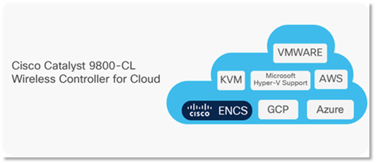
The IOS XE based Cisco Cloud Wireless LAN Controller sets the standard for Infrastructure as a Service (IaaS) secure wireless network services in the Microsoft Azure cloud, bringing the world's most popular networking wireless platform to Azure.
The Public Cloud model chosen for the Cisco Catalyst 9800 for Cloud is Infrastructure as a Service (IaaS). In this model, the Public Cloud vendor provides the networking, computing, and security infrastructure while the customer fully manages the C9800-CL virtual machine in the cloud.
There are many advantages in adopting Public Cloud, let’s list the ones that are most significant for the Catalyst 9800:
· Agility: it takes a few minutes to spawn a C9800 instance in Azure. This makes it easy to quickly launch a wireless controller to test some new feature or functionality and terminate it when done.
· Scalability: There are no physical limits in the public cloud, so new instances can be added as the requirements for additional APs or clients increase
· Global footprint: This is important for latency but also for security and privacy policies. The public cloud providers have a global footprint so from any location that APs installed to reach a C9800-CL in the cloud with a lower latency. Some customers have a strict security policy dictating that user data and traffic need to stay within the region; the public cloud providers have a Data Center in every geographical region.
· Cost effectiveness: reduce data center footprint and infrastructure costs. Shift from a capital expenditure (buying up front) model to an operational expenditure model.
Integration with Azure Marketplace
On Azure’s Marketplace, there are multiple types of offerings for any given product. Only 2 options are applicable for C9800-CL to keep it consistent with AWS and GCP.
1. Azure Virtual Machine: Cisco provides only the image to the user, and it is up to the user to configure the VM as per the data sheet.
2. Azure Application: “Azure application” allows us to support automating the deployment and configuration of a solution beyond a single virtual machine (VM). It can simplify the process of providing multiple resources, including VMs, networking, and storage resources to provide complex solutions.
Required Resources
Like AWS and GCP, Cisco support the following template. Users will be able to choose the scale when launching via marketplace.
 For more details on required resources and scale information, please visit Datasheet here
MS Azure Deployment
Section 0: Azure Deployment Workflow

Above is an example of Cisco Catalyst 9800 Wireless Controller Deployment in Azure. Please look at this workflow below that will help better understand and build up the deployment.

Section 1: Create Resource Group
Step1:

On MS Azure Home Page, Search for resource groups and Click on the result.

Click on “Create”.
Step2:
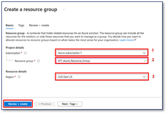
1. Select a subscription.
2. Give a name to the new resource group.
3. Select the region for the resource group.
Section 2: Create Azure Virtual Network
Step 1:
On MS Azure Home Page, Search for Virtual networks and click on the search result. And then click on “Create”

Step2:
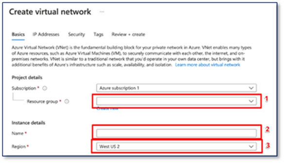
1. Select the resource group that just created.
2. Give a name to the Virtual network
3. Select a region for the deployment.
Step 3:

1. Click on “IP Address”
2. Enter the IPv4 address space for the Virtual network
3. Add subnets to the IPv4 address space
Note: The Virtual Ip address space and subnet should be different from the Campus network.
Note: The IPv4 address space and subnet are in CIDR notation e.g., 10.1.1.0/24
Step 3:
Click on “Security”, leave the following in default:
- DDoS protection: Disabled
- Firewall: Disabled
Click on “Review + create” and review the configuration and click on “Create”.

Section 3: Create Network Security Group (for Azure Virtual Machine Only)
Note: This step is for deploying with Azure Virtual Machine only. If deploying with Azure Application, a network security group will be automatically generated by the preconfigured template in its resource group, it is not needed to create a new one here.
Step1:
On the Search bar, Search for “Network Security Group” and click on the search result. 
Step2:
Click on “Create” and then: 
1. Choose the resource group just created.
2. Give a name to the network security group.
3. Select current region for the deployment.
Click on “Review Create” and “Create”.
Step3: Add inbound rule
Go back to Network Security Group page and click on the security group just created.
On the left menu click on “Inbound Security Rules”
Click on “add”

1. Add typical ports that are needed for the traffic going into the instance. For Security reason, only allow ports are needed based on the network architect. Below is a list of ports with corresponding protocol that Cisco Catalyst 9800-CL is normally used.
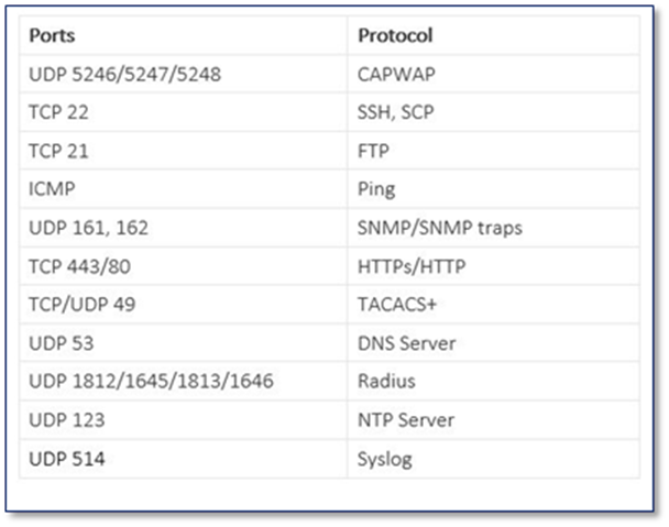
2. Give priority to this rule, rules are processed with priority order. The lower priority number is, the higher priority it has.
3. Give a name to this rule.
Repeat this process until all the rules have been added to the inbound rule.
Outbound Rules will be by default allow all. There is no requirement to change the default outbound rules.
Section 4: Managed VPN
Note:
From 17.8.1 release, onboarding through public IP for APs is supported on all public cloud platforms. Please refer to Section 6.
Note:
As of 17.7.1, the C9800-CL in Azure does not support use of the public IP. For AP join, the APs need to be behind a VPN. Please follow the steps below to establish a VPN connection to on-prem network.

4.1 Create Virtual Network Gateway
Step1: On the top Search bar, search for “Virtual network gateways” and click on the result

Step2: Click on “Create”

Step3:


1. Give a name for the gateway
2. Select current region for the deployment
3. Select the virtual network that you want to associate with the gateway, in this case, it will be the subnet where the C9800-CL is going to be located.
4. A new IP address can be created here, or it is also an option to choose the existing public IP address from the drop-down menu.
5. Give a name to the public IP address (only apply for creating a new public IP address)
6. Select the Availability zone
Click on “Review + create” and then “Create”
4.2 Create Local Network Gateway
Step1: On the top Search bar, search for “Local Network Gateways”, and click on the search result.

Step2: Click on “Create”
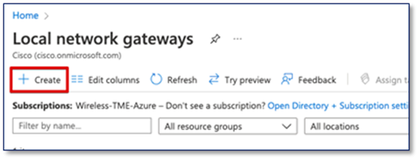
Step3:

1. Select the resource group for the deployment.
2. Select the current region of the deployment.
3. Give a name for the Local Network Gateway
4. Enter the public facing IP address from the On-Prem router
5. Add the address spaces from your On-Prem router.
Click on “Review + create” and then “Create”
4.3 Add Connection
Step1: Go to Virtual network gateways and click on the gateway that just deployed.

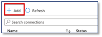
Step2: On the left side menu, select “Connections” and then “Add”

Step3:
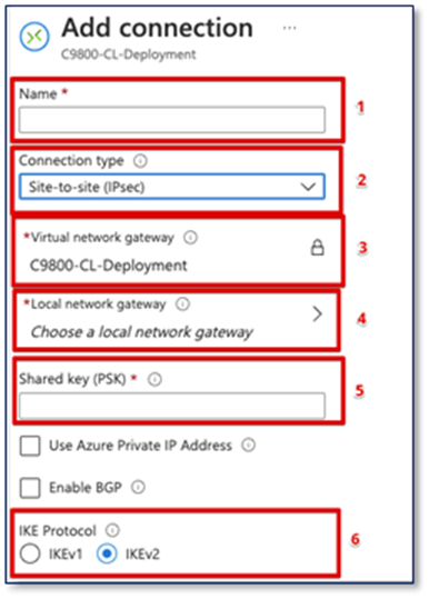
1. Give a name for the connection
2. Select Site-to-Site (IPsec)
3. Keep it as the current Virtual network gateway
4. Choose the local network gateway that just created
5. Give a Shared key for the connection
6. Select IKEv2
Click on “OK” on the bottom
4.4 Download configuration and apply to router
After the connection is deployed, you can download the configuration in the connection page.
Step1: Click on “Download configuration”

Step2: Download the configuration for the on-prem router.
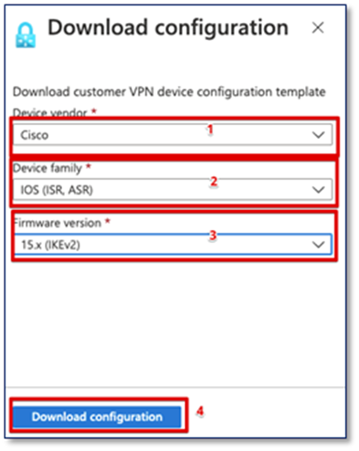
1. Select the Device Vendor
2. Select the device family
3. Select 15.x (IKEv2)
4. Click on Download Configuration
Step3: Write the downloaded configuration in the router configuration, there is also rollback script at the end of the file to delete all the configuration that applied.
It will take about 5 mins for the connection to be established, the status of the connection will change to connected.

For more information regarding VPN connection, please check it here.
Section 5: Deploy the Catalyst 9800-CL Instance in Microsoft Azure
5.1 Deploy Catalyst 9800-CL Instance by Azure Virtual Machine
Step 1:
Click on Marketplace, Search for “Cisco Catalyst 9800-CL Wireless Controller”. Click on the box with “Virtual Machine”

Click on “Create”

Step 2: Basics
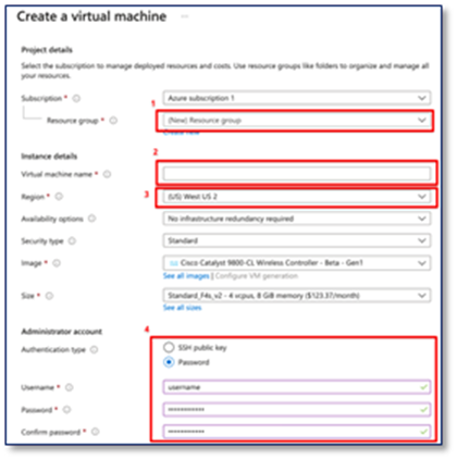
1. Click on Resource Group drop down menu and choose the Resource group just created
2. Give a name to C9800-CL, this name will also be your hostname after it deployed.
3. Select the Region that the C9800-CL is going to be deployed. Region needs to be chosen as the same region of the VPN.
4. In Authentication type, there are 2 options. For SSH public key, Azure will generate an SSH key pair to for SSH connection and could be stored for future use, existing key pair could also be uploaded and stored. For Password, a pair of username/password need to be entered for remote access to the console terminal (SSH/Telnet).
Click on “Next : Disk”.
Step 3: Disk
Leave this page on default and click on “Next : Networking”
Step 4: Networking
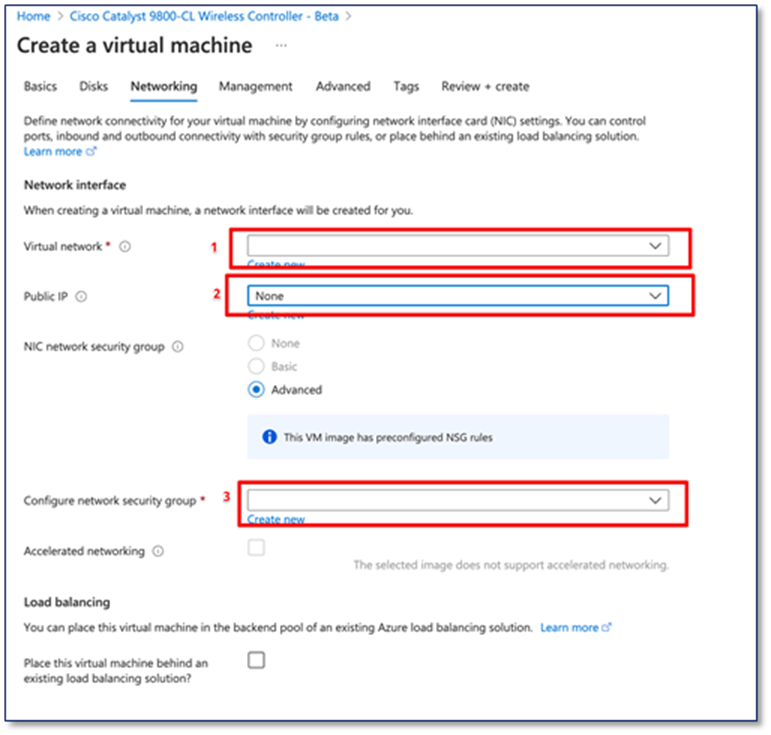
1. Under the Virtual network drop-down menu, click on the virtual network that created in the Resource group.
2. The C9800-CL can be accessed via the public IP address, a new public IP address can be created here, or an existing public IP address can be selected from the drop-down menu.
3. Choose the network security group that was created previously in the drop-down menu.
Click on “Next : Management”.
Step 5: Management
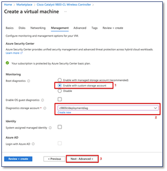
(Optional) It is recommended to enable the custom storage account and create a new Diagnostics storage account, for console connection access from Azure serial console feature when you lose connection with the C9800-CL.
1. Select Enable with custom storage account
2. Create new or select the existing Diagnostics storage account
3. Click on “Next : Advanced”
Step 6: Advanced

The IOS bootstrap config can be input in Custom data box for configuring the VM while it is being provisioned.
Example format:
username admin privilege 15 password 0 admin123
Click on “Review + Create” and then “Create”
Step 7: Day 0 Configuration
After the deployment is done, the C9800-CL can be accessed with WebUI via public IP address or Private IP address for Day 0 Configuration page, the Steps on Day 0 configurations and after are the same as deploying C9800-CL on AWS and GCP. SSH and serial console will be used for Day 1 configuration.

For more information on configuration, please click here.
5.2 Deploy Catalyst 9800-CL Instance by Azure Application
Deploying the C9800-CL from Azure Application requires an empty resource group, it is required to create a new resource group prior the deployment process or during the deployment process, for more detail on creating resource group prior the deployment process, please check the section “MS Azure Deployment-Create Resource Group”.
Step1:
Click on Marketplace, Search for “Cisco Catalyst 9800-CL Wireless Controller”. Click on the box with “Azure Application”

Click on “Create”

Step2: Basics
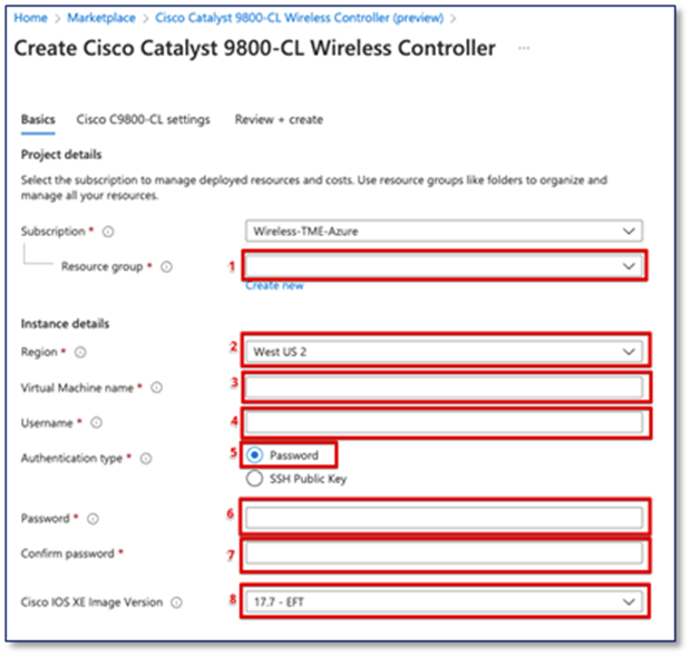
1. Select the newly created empty resource group, if there is no empty resource group, click on “Create new” under the drop-down menu.
2. Select your current region
3. Give a name to the C9800-CL, it will also be the host name of the device
4. Give a login username for the C9800-CL
5. In Authentication type, there are 2 options. For SSH public key, Azure will generate an SSH key pair to for SSH connection and could be stored for future use, existing key pair could also be uploaded and stored. For Password, a pair of username/password need to be entered for remote access to the console terminal (SSH/Telnet). In the username bar, give it an administrator username for C9800-CL
6. Give a login password for the C9800-CL
7. Confirm the password
8. Select an Image Version for the C9800-CL.
Click on “Next : Cisco C9800-CL settings”
Step3: Cisco C9800-CL settings
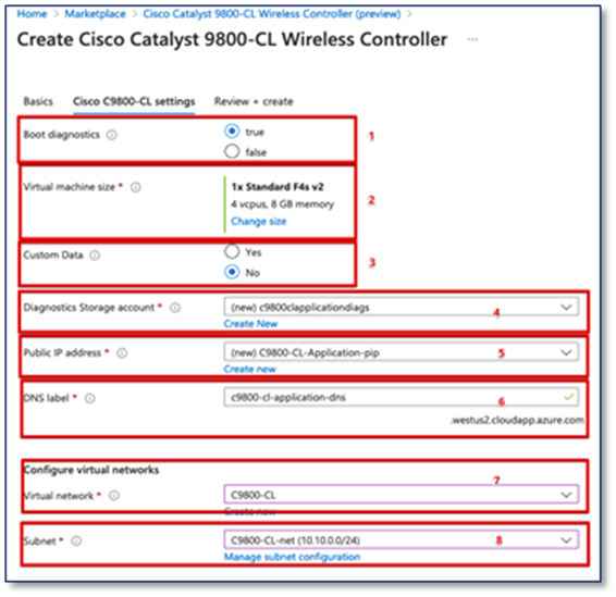
1. Select true on Boot diagnostics
2. The default size of the VM is the smallest scale, the size can be changed by clicking on “Change size” and choose between the three different sizes as shown below:

3. If there is bootstrap configuration that would like to be uploaded, select “Yes”, otherwise click on “No”.
4. Diagnostics Storage account is recommended, it is for connecting and screening the serial console. A new Diagnostic account can be created here.
5. The C9800-CL can be accessed via the public IP address, a new public IP address can be created here.
6. Keep it as default.
7. Select the Virtual network that maps the VPN connection that configured.
8. Select the Subnet that maps the VPN connection that configured.
Click on “Review + create” and then Click on “Create”
Step 4: Day 0 Configuration
After the deployment is done, the C9800-CL can be accessed with WebUI via public IP address or Private IP address for Day 0 Configuration page, the Steps on Day 0 configurations and after are the same as deploying C9800-CL on AWS and GCP. SSH and serial console will be used for Day 1 configuration.
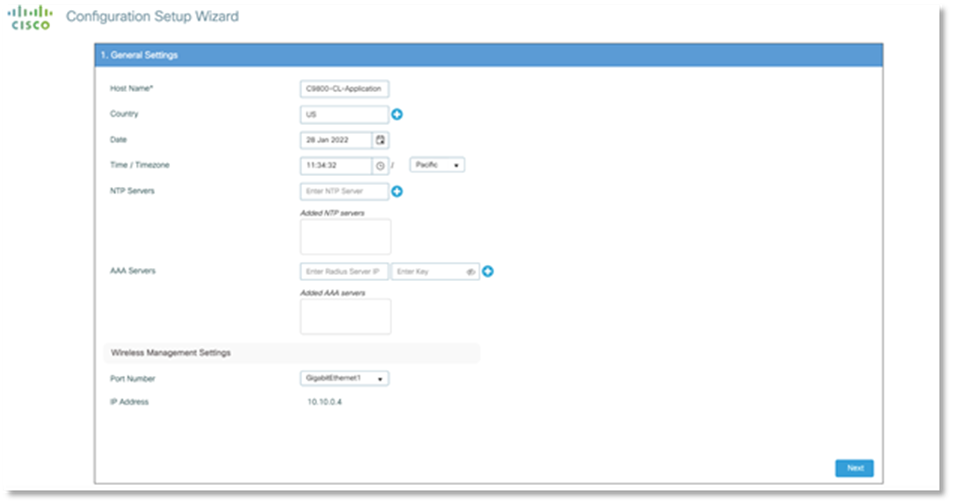
For more information on configuration, please click here.
Section 6: Enable Public IP for AP to onboard
From 17.8.1 release, onboarding through public IP for APs is supported on public cloud. Please upgrade the image to 17.8.1 before performing the following feature.
Step1: Enable public Discovery in AP join profile
WebUI Configuration:

In Main Menu, Select Configuration -> Tags & Profile -> AP join

Click on the AP join Profile currently using.

1. Click on CAPWAP
2. Click on Advanced
3. Make sure Public Discovery is enabled.
CLI Configuration:
1. configure terminal
example: C9800-CL-VM#configure terminal
2. ap profile <AP Join Profile Name>
example: C9800-CL-VM(config)# ap profile default-ap-profile
3. capwap-discovery public
example: C9800-CL-VM(config-ap-profile)# capwap-discovery public
Note:
If Public Discovery and Private Discovery are enabled at the same time in the AP join Profile. APs that with VPN connection will have a chance to join via public IP if it has the public IP access.
To avoid this, it is needed to create a separate AP site tag and AP join profile with only Private Discovery enabled for these APs that need to be private onboarded.
Step2: Add NAT-IP address on Wireless Management Interface
WebUI Configuration:

In the Main Menu, Select Configuration -> Interface -> Wireless

Click on the current management wireless interface
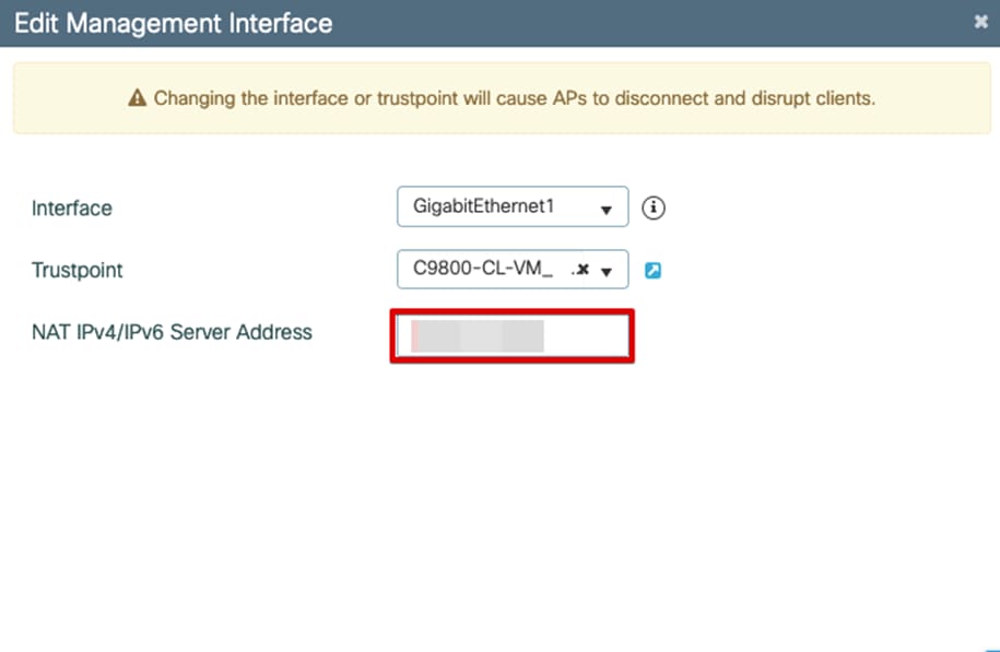
Edit the Wireless Management Interface NAT IPv4/IPv6 Server Address to the public IP address of the WLC.
CLI Configuration:
1. configure terminal
example: C9800-CL-VM#configure terminal
2. wireless management interface <Wireless Management Interface>
example: C9800-CL-VM(config)# wireless management interface GigabitEthernet1
3. public-ip <Public IP address of the WLC>
example: C9800-CL-VM(config-mgmt-interface)# public-ip xxx.xxx.xxx.xxx
Step3: Configure Primary base on AP console
CLI configuration on AP console:
1. capwap ap primary-base <Host name of WLC> <Public IP address of WLC>
example: AP# capwap ap primary-base C9800-CL xxx.xxx.xxx.xxx
2. capwap ap restart
example: AP# capwap ap restart
Now the AP will restart the CAPWAP process and join WLC via Public IP address
Contact Cisco
- Open a Support Case

- (Requires a Cisco Service Contract)
 Feedback