Application Visibility and Control Feature Deployment Guide
Available Languages
Table of Contents
Application Visibility and Control Feature Deployment Guide rel 7.4-8.2
Application Visibility and Control Release Update
Application Visibility and Control—Phase 1
Application Visibility and Control–Phase 2
AVC and QoS Interaction on the WLAN
AVC Operation with Anchor/Foreign Controller’s Setup
Loading AVC Protocol Pack–Phase 2
Configure Application Visibility
Configure NBAR NetFlow Monitor
AVC—Phase 3 in CUWN Release 8.0
AAA AVC Profile Override for Clients
Steps to Configure Application Visibility Per User Role
AAA Configuration for AVC Profile
Application Rate Limiting Through AVC
AVC Profiles Attached to Local Policies
Introduction to Profiling and Policy Engine on the WLC
Profiling and Policy Configuration
Creating Policies on the WLAN from the WLC GUI
AVC—Phase 4 in CUWN Release 8.2
Protocol Pack and NBAR Engine Update
Netflow Deployment Considerations
Obtaining Lancope Software for Evaluation Purposes (Reference)
Netflow Configuration on the WLC
Application Visibility and Control Feature Deployment Guide rel 7.4-8.2
Application Visibility and Control Release Update
Application Visibility and Control—Phase 1
Network Based Application Recognition (NBAR) provides application-aware control on a wireless network and enhances manageability and productivity. It also extends Cisco’s Application Visibility and Control (AVC) as an end-to-end solution, which gives a complete visibility of applications in the network and allows the administrator to take some action on the same.
NBAR is a deep-packet inspection technology available on Cisco IOS based platforms, which supports stateful L4 - L7 classification. NBAR2 is based on NBAR and has extra requirements such as having a Common Flow Table for all IOS features which use NBAR. NBAR2 recognizes application and passes on this information to other features like QoS, NetFlow and Firewall, which can take action based on this classification.
The key use cases for NBAR are capacity planning, network usage base lining and better understanding of what applications are consuming bandwidth. Trending of application usage helps network admin to plan for network infrastructure upgrade, improve quality of experience by protecting key applications from bandwidth-hungry applications when there is congestion on the network, capability to prioritize or de-prioritize, and drop certain application traffic.
NBAR is supported on 2500, 5500, 7500, 8500 and WiSM2 controllers on Local, Mesh, and Flex Mode APs (for WLANs configured for central switching only).
NBAR Supported Feature
NBAR as a feature can perform the following tasks:
1.![]() Classification–Identification of Application/Protocol.
Classification–Identification of Application/Protocol.
2.![]() AVC–Provides visibility of classified traffic and also gives an option to control the same using Drop or Mark (DSCP) action.
AVC–Provides visibility of classified traffic and also gives an option to control the same using Drop or Mark (DSCP) action.
3.![]() NetFlow–Updating NBAR stats to NetFlow collector like Cisco Prime Assurance Manager (PAM).
NetFlow–Updating NBAR stats to NetFlow collector like Cisco Prime Assurance Manager (PAM).
Application Visibility and Control–Phase 2
In phase two of the AVC support for Protocol Packs has been added. Protocol packs are software packages that allow update of signature support without replacing the image on the Controller. You have an option to load protocol packs dynamically when new protocol support is being added. There are two kinds of Protocol Packs—Major and Minor:
■![]() Major protocol packs include support for new protocols, updates, and bug fixes.
Major protocol packs include support for new protocols, updates, and bug fixes.
■![]() Minor protocol packs typically do not include support for new protocols.
Minor protocol packs typically do not include support for new protocols.
■![]() Protocol packs are targeted to specific platform types, software versions and releases separately. Protocol Packs can be downloaded from CCO using the software type “NBAR2 Protocol Pack”.
Protocol packs are targeted to specific platform types, software versions and releases separately. Protocol Packs can be downloaded from CCO using the software type “NBAR2 Protocol Pack”.
Protocol packs are released with specific NBAR engine versions. For example, WLC 7.5 has NBAR engine 13, so protocol packs for it are written for engine 13 (pp-unified-wng-152-4.S-13-4.1.1.pack). Loading a protocol pack can be done if the engine version on the platform is same or higher than the version required by the protocol pack (13 in the example above). Therefore for example – PP4.1 for 3.7 (version 13) can be loaded on top of 3.7 (version 13) and 3.8, but PP4.1 for 3.8 cannot be loaded on top of 3.7. It is strongly recommended to use the protocol pack that is the exact match for the engine.
For AVC phase 2, protocol packs can be downloaded directly from CCO–Protocol Pack 4.1.1 for engine XE 3.7. The protocol pack file “pp-AIR-7.5-13-4.1.1.pack” (Format: pp-AIR-{release}-{engine version}-M.m.r.pack) will be located in the same location with the controller code version 7.5. This is the only tested and supported protocol pack released with controller software version 7.5.
Note: If you download the protocol pack from the below link where protocol packs for other Cisco devices is posted for download, the protocol packs might work but will not be supported. See http://software.cisco.com/download/release.html?mdfid=282993672&flowid=20841&softwareid=284509011&release=4.0.0&relind=AVAILABLE&rellifecycle=&reltype=latest

Complete list of the protocols supported in the release posted at the link below
http://www.cisco.com/en/US/docs/ios-xml/ios/qos_nbar/prot_lib/config_library/
nbar-prot-pack-library.html
Note: For AVC Phase 2 the downloadable NBAR Protocol Packs are supported on 5500, 7500, 8500 and WiSM2 controllers on Local, Mesh, and Flex Mode APs (for WLANs configured for central switching only). The 2500 series controllers do not support Protocol Packs.
NBAR/AVC Facts
■![]() NBAR/AVC phase 2 on WLC can classify and take action on 1054 different applications.
NBAR/AVC phase 2 on WLC can classify and take action on 1054 different applications.
■![]() Two actions, either DROP or MARK is possible on any classified application.
Two actions, either DROP or MARK is possible on any classified application.
■![]() Maximum 16 AVC profiles can be created on a WLC.
Maximum 16 AVC profiles can be created on a WLC.
■![]() Each AVC profile can be configured with a maximum 32 rules.
Each AVC profile can be configured with a maximum 32 rules.
■![]() Same AVC profile can be mapped to multiple WLANs. But one WLAN can have only one AVC profile.
Same AVC profile can be mapped to multiple WLANs. But one WLAN can have only one AVC profile.
■![]() Only 1 NetFlow exporter and monitor can be configured on WLC.
Only 1 NetFlow exporter and monitor can be configured on WLC.
■![]() NBAR/AVC stats are displayed only for top 10 applications on GUI. CLI can be used to see all applications.
NBAR/AVC stats are displayed only for top 10 applications on GUI. CLI can be used to see all applications.
■![]() NBAR/AVC is supported on WLANs configured for central switching only.
NBAR/AVC is supported on WLANs configured for central switching only.
■![]() If AVC profile mapped to WLAN has a rule for MARK action, that application will get precedence as per QOS profile configured in AVC rule overriding the QOS profile configured on WLAN.
If AVC profile mapped to WLAN has a rule for MARK action, that application will get precedence as per QOS profile configured in AVC rule overriding the QOS profile configured on WLAN.
■![]() Any application, which is not supported/recognized by NBAR engine on WLC, is captured under the bucket of UNCLASSIFIED traffic.
Any application, which is not supported/recognized by NBAR engine on WLC, is captured under the bucket of UNCLASSIFIED traffic.
■![]() IPv6 traffic cannot be classified.
IPv6 traffic cannot be classified.
■![]() AAA override of AVC profiles is not supported.
AAA override of AVC profiles is not supported.
■![]() AVC profile can be configured per WLAN and cannot be applied per user basis.
AVC profile can be configured per WLAN and cannot be applied per user basis.
■![]() Begin with release 8.1.102.0 AVC is supported on the vWLCs with FC APs in a locally switched mode.
Begin with release 8.1.102.0 AVC is supported on the vWLCs with FC APs in a locally switched mode.
AVC and QoS Interaction on the WLAN
The AVC/NBAR2 engine on the controller interoperates with the QoS settings on the specific WLAN. The NBAR2 functionality is based on the DSCP setting. The following occurs to the packets in Upstream and Downstream directions if AVC and QoS are configured on the same WLAN:
1.![]() Packet comes with or without inner DSCP from wireless side (wireless client).
Packet comes with or without inner DSCP from wireless side (wireless client).
2.![]() AP will add DSCP in the CAPWAP header that is configured on WLAN (QoS based configuration).
AP will add DSCP in the CAPWAP header that is configured on WLAN (QoS based configuration).
3.![]() WLC will remove CAPWAP header.
WLC will remove CAPWAP header.
4.![]() AVC module on the controller will overwrite the DSCP to the configured marked value in the AVC profile and send it out.
AVC module on the controller will overwrite the DSCP to the configured marked value in the AVC profile and send it out.
1.![]() Packet comes from switch with or without inner DSCP wired side value.
Packet comes from switch with or without inner DSCP wired side value.
2.![]() AVC module will overwrite the inner DSCP value.
AVC module will overwrite the inner DSCP value.
3.![]() Controller will compare WLAN QoS configuration (as per 802.1p value that is actually 802.11e) with inner DSCP value that NBAR had overwritten. WLC will choose the lesser value and put it into CAPWAP header for DSCP.
Controller will compare WLAN QoS configuration (as per 802.1p value that is actually 802.11e) with inner DSCP value that NBAR had overwritten. WLC will choose the lesser value and put it into CAPWAP header for DSCP.
4.![]() WLC will send out the packet to AP with QoS WLAN setting on the outer CAPWAP and AVC inner DSCP setting.
WLC will send out the packet to AP with QoS WLAN setting on the outer CAPWAP and AVC inner DSCP setting.
5.![]() AP strips the CAPWAP header and sends the packet on air with AVC DSCP setting; if AVC was not applied to an application then that application will adopt the QoS setting of the WLAN.
AP strips the CAPWAP header and sends the packet on air with AVC DSCP setting; if AVC was not applied to an application then that application will adopt the QoS setting of the WLAN.
AVC Operation with Anchor/Foreign Controller’s Setup
In the case of Anchor and Foreign controller’s configuration, the AVC has to be configured where the application control essentially is required. In most cases in Anchor/Foreign setups the AVC should be enabled on the Anchor controller. AVC profile enforcement will happen on the WLAN on the Anchor controller. If Anchor controller is release 7.4 or higher the above mentioned setup will work.
Loading AVC Protocol Pack–Phase 2
Loading of Protocol Packs is supported only via the command line interface. The command to load a protocol pack is shown in the example below:
(Cisco Controller) >transfer download datatype avc-protocol-pack
(Cisco Controller) >transfer download start
Mode.............................. FTP
Data Type......................... AVC Protocol Pack
FTP Server IP..................... A.B.C.D
FTP Server Port................... 21
FTP Path.......................... /
FTP Filename..................... pp-unified-wng-152-4.S-13-4.1.1.pack
FTP Username...................... cisco
FTP Password...................... *********
Starting transfer of AVC Protocol Pack
Are you sure you want to start? (y/N)
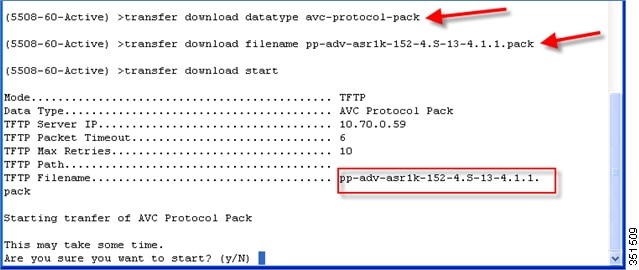
The download process might take some time.

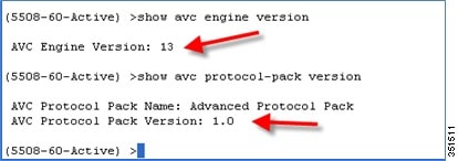
Use the show command to view the currently loaded protocol pack
(Cisco Controller) >show avc protocol-pack version
AVC Protocol Pack Name: Advanced Protocol Pack
AVC Protocol Pack Version: 1.0
Use the show command to view the current Nbar2 Engine Version
(Cisco Controller) >show avc engine version
Before installing the Protocol Pack the default pack will show as follow:
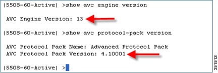
After installing the Protocol Pack the AVC pack will show as version 4.10001:
Configure Application Visibility
1.![]() Open a web browser on the Wired Laptop. Enter your WLC IP Address.
Open a web browser on the Wired Laptop. Enter your WLC IP Address.
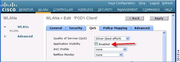
2.![]() Create an OPEN WLAN with naming convention as for example: “POD1-Client” and enable Application Visibility on that WLAN under QOS TAB. Map this WLAN to management interface.
Create an OPEN WLAN with naming convention as for example: “POD1-Client” and enable Application Visibility on that WLAN under QOS TAB. Map this WLAN to management interface.
To enable Application visibility, click WLAN ID and then click the QOS tab and check the enable option for Application Visibility and click Apply.

3.![]() Once Application Visibility is enabled on the specific WLAN, from the associated wireless client start different types of traffic using the applications (already installed) like Cisco Jabber/WebEx Connect, Skype, Yahoo Messenger, HTTP, HTTPS/SSL, Microsoft Messenger, YouTube, Ping, Trace route, etc. Once traffic is initiated from wireless client, visibility of different traffic can be observed globally for all WLANs, Per Client Basis and Per WLAN Basis which provides a good overview to the administrator of the network bandwidth utilization and type of traffic in the network per client, per WLAN, and globally.
Once Application Visibility is enabled on the specific WLAN, from the associated wireless client start different types of traffic using the applications (already installed) like Cisco Jabber/WebEx Connect, Skype, Yahoo Messenger, HTTP, HTTPS/SSL, Microsoft Messenger, YouTube, Ping, Trace route, etc. Once traffic is initiated from wireless client, visibility of different traffic can be observed globally for all WLANs, Per Client Basis and Per WLAN Basis which provides a good overview to the administrator of the network bandwidth utilization and type of traffic in the network per client, per WLAN, and globally.
As mentioned above Visibility of traffic can be monitored:
4.![]() To check the visibility globally for all WLANs on WLC, click and scroll down.
To check the visibility globally for all WLANs on WLC, click and scroll down.
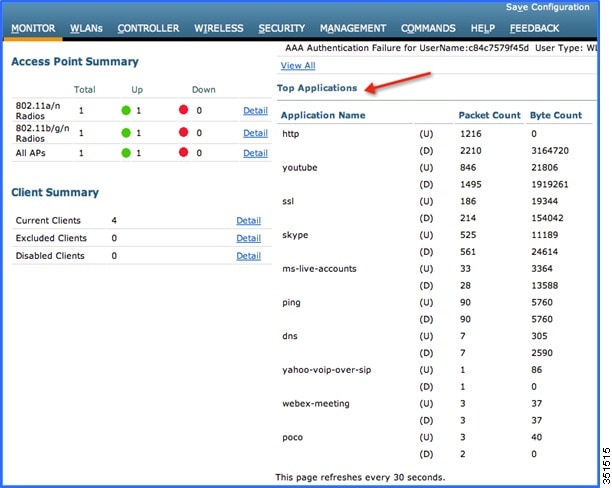
Note: The monitor screen list the applications classified by NBAR engine running on WLC for all the WLANs. The top ten applications in the last 90 seconds in both Upstream (U) and Downstream (D) directions will be listed on this page.
5.![]() To have more granular visibility per WLAN, navigate to Monitor > Applications. This page will list all the WLANs on which AVC visibility is enabled.
To have more granular visibility per WLAN, navigate to Monitor > Applications. This page will list all the WLANs on which AVC visibility is enabled.
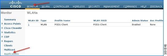
Now click the individual WLAN ID and the below screen will be visible which will list aggregate data for the top ten applications running on that particular WLAN.
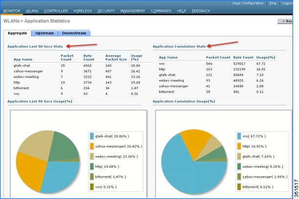
Note: This page will provide more granular visibility per WLAN and will list the top ten applications in last the 90 seconds, as well as cumulative stats for the top ten applications. The above screen lists the aggregate traffic on a particular WLAN, which includes upstream as well as downstream data. You can view UPSTREAM and DOWNSTREAM stats individually per WLAN from same page by clicking the Upstream and Downstream tab.
6.![]() To have further granular visibility of the top ten applications per client on a particular WLAN on which AVC visibility is enabled, navigate to Monitor > Clients and click any individual client MAC entry listed on that page.
To have further granular visibility of the top ten applications per client on a particular WLAN on which AVC visibility is enabled, navigate to Monitor > Clients and click any individual client MAC entry listed on that page.

After clicking on an individual client MAC entry listed on the above page, the client details page will open which will have two tabs; one for general information and another tab with the name AVC Statistics. Click the AVC Statistics tab to see the NBAR statistics for the top ten applications for that particular client.
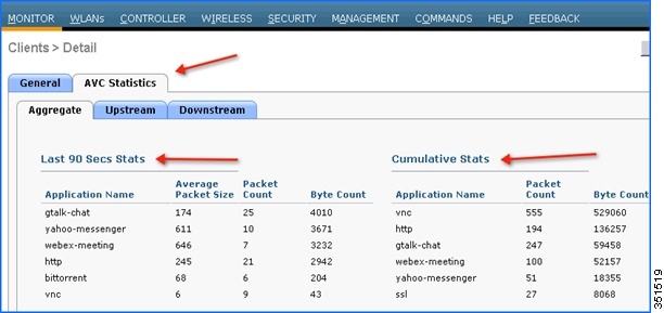
Note: This page will provide further granular stats per client associated on WLAN on which Application Visibility is enabled and will list the top ten applications in last 90 seconds as well as cumulative stats for top ten applications. The above screen lists the aggregate traffic per client, which includes upstream as well as downstream stats. You can view UPSTREAM and DOWNSTREAM stats individually per client from same page by clicking the Upstream and Downstream tab.
Configure AVC Profile
1.![]() The NBAR feature on a WLC not only gives a visibility of applications running in the network, but also gives the administrator an option to control the applications running in the network by creating an AVC profile. AVC profiles can be configured to take the following actions on the recognized applications:
The NBAR feature on a WLC not only gives a visibility of applications running in the network, but also gives the administrator an option to control the applications running in the network by creating an AVC profile. AVC profiles can be configured to take the following actions on the recognized applications:
a.![]() Action DROP (Traffic for that application will be dropped)
Action DROP (Traffic for that application will be dropped)
b.![]() Action MARK (Particular applications can be marked with different QOS profiles available on WLC, or the administrator can custom define the DSCP value for that application)
Action MARK (Particular applications can be marked with different QOS profiles available on WLC, or the administrator can custom define the DSCP value for that application)
2.![]() To see all the applications supported by NBAR engine for stats, visibility and control action (DROP/MARK), navigate to Wireless > Application Visibility And Control > AVC Applications. This page will list down all the applications in sorted order with the application group they belong.
To see all the applications supported by NBAR engine for stats, visibility and control action (DROP/MARK), navigate to Wireless > Application Visibility And Control > AVC Applications. This page will list down all the applications in sorted order with the application group they belong.
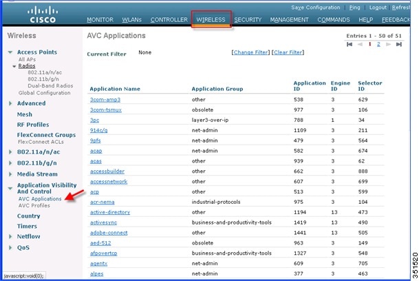
Note: While creating the drop/mark action for any application under AVC profile, application group need to be selected first. This page list down all the applications with application group they belong and with simple lookup for application using browser “FIND” option, an administrator can find applications and its group and use this group in AVC profile to configure drop/mark action which is discussed further in this guide. NBAR on WLC supports visibility of 1054 different applications.
3.![]() To configure any action (drop/mark), the AVC profile should be created first. To configure the AVC profile, navigate to Wireless > Application Visibility And Control > AVC Profiles and then click New to create the AVC profile.
To configure any action (drop/mark), the AVC profile should be created first. To configure the AVC profile, navigate to Wireless > Application Visibility And Control > AVC Profiles and then click New to create the AVC profile.
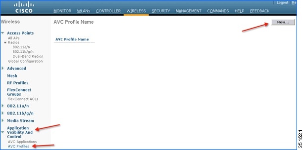
4.![]() Enter AVC profile name and click Apply.
Enter AVC profile name and click Apply.

5.![]() After Apply is clicked, the AVC profile will be created and you can see the above-created profile, which can be clicked further to create rules to take drop/mark action. Maximum of 16 AVC profiles can be created on a WLC.
After Apply is clicked, the AVC profile will be created and you can see the above-created profile, which can be clicked further to create rules to take drop/mark action. Maximum of 16 AVC profiles can be created on a WLC.

6.![]() After creating the AVC profiles, you can click on any profile name and create rules for individual profiles. Maximum of 32 rules can be configured in each profile. Rules can be configured to take any of the two actions i.e. DROP or MARK. If no rule is configured for any application the default action will be “Allow” with QOS policy configured on a WLAN. To create rules under profile, navigate to Wireless > Application Visibility And Control > AVC Profiles and then click any of the above created profile.
After creating the AVC profiles, you can click on any profile name and create rules for individual profiles. Maximum of 32 rules can be configured in each profile. Rules can be configured to take any of the two actions i.e. DROP or MARK. If no rule is configured for any application the default action will be “Allow” with QOS policy configured on a WLAN. To create rules under profile, navigate to Wireless > Application Visibility And Control > AVC Profiles and then click any of the above created profile.

7.![]() Now click Add New Rule and the below page (2nd screen shot) is displayed where the administrator can select the application group from the first drop-down which filters the applications that belong to that group only. Then, from the second drop-down application can be selected. Once the application is selected from second drop down, the administrator can select what action should be taken on that application from third the drop-down. Once the action is selected click Apply.
Now click Add New Rule and the below page (2nd screen shot) is displayed where the administrator can select the application group from the first drop-down which filters the applications that belong to that group only. Then, from the second drop-down application can be selected. Once the application is selected from second drop down, the administrator can select what action should be taken on that application from third the drop-down. Once the action is selected click Apply.


Note: In 7.5 release, WLC is capable of classifying 1054 applications and provide an option to take any action. To take an action on any application, the administrator has to select application group first to which that application belongs which will filter the list of applications for that application group only. The reason for this implementation is all 1054 applications cannot be displayed in a single drop-down. Also in release 7.5, the Application Names are now selectable and by hovering over and clicking the application name in the list the above profile rule can be created.
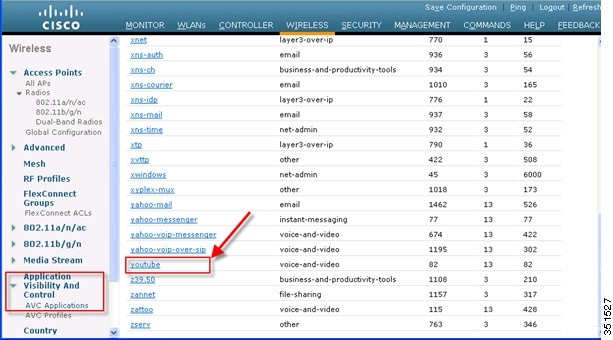
8.![]() After Apply is clicked, the action rule will be created and displayed as captured in the below screen. You can add more rules under the AVC profile on the same page. Maximum of 32 rules can be configured in a single AVC profile.
After Apply is clicked, the action rule will be created and displayed as captured in the below screen. You can add more rules under the AVC profile on the same page. Maximum of 32 rules can be configured in a single AVC profile.

9.![]() Another rule can be configured under the same AVC profile to MARK traffic with a different QOS profile or custom DSCP value. In this example, another AVC profile was created following step 3, 4 and 5 with the name “Mark_Http_Webex”. In this example this AVC profile is used to create a rule to mark “Http” with low priority and give “Webex” more precedence.
Another rule can be configured under the same AVC profile to MARK traffic with a different QOS profile or custom DSCP value. In this example, another AVC profile was created following step 3, 4 and 5 with the name “Mark_Http_Webex”. In this example this AVC profile is used to create a rule to mark “Http” with low priority and give “Webex” more precedence.

As discussed in previous steps 6, 7 and 8, click the AVC profile name to create rules for the profile. Click Add New Rule.

Select Application group from the first drop-down and Application name as Webex from second drop-down. Then, configure Action as MARK and select QOS profile as Platinum and the click Apply.

After Apply is clicked, the action rule will be created and displayed as captured in below screen. Click Add New Rule on same page to create another rule to MARK another application “Http”.

Create another rule in the same profile by just clicking Add New Rule on the same page. Select Application group from the first drop-down and Application name as http from second drop-down. Then, configure Action as Mark with QOS profile as Bronze. Then click Apply.

After Apply is clicked, the action rule will be created and displayed as captured in below screen.

Note: For the same AVC profile two rules are created. The Administrator can configure up to 32 rules in the same AVC profile. Individual rules can be configured for action MARK or DROP in the same profile. A single rule can only be configured with a single action i.e. either MARK or DROP.
The administrator is also flexible while configuring Action as MARK to choose the Differentiated Services Code Point (DSCP) value as Custom instead of selecting “Platinum/Gold/Silver/Bronze”. Once Custom is selected as DSCP value, a text filed will be visible where admin can enter a custom DSCP value in range of 0 - 63.
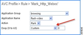
10.![]() The Next step will be to apply these AVC profiles on the WLAN. Only one AVC profile can be mapped to a single WLAN. A single AVC profile can be mapped to multiple WLANs. Once an AVC profile is mapped to a WLAN and if it has a rule for MARK action, that application will get precedence as per QoS profile configured in AVC rule interacting with the QOS profile configured on the WLAN. All the AVC profiles created will be visible under AVC Profile drop-down in WLAN under QOS TAB. To see the AVC profile in the drop-down on WLAN, navigate to WLANs > WLAN ID and then click QOS tab. All the AVC profiles created are visible under the AVC Profile drop-down. The administrator can select the AVC profile on the WLAN as per network requirement.
The Next step will be to apply these AVC profiles on the WLAN. Only one AVC profile can be mapped to a single WLAN. A single AVC profile can be mapped to multiple WLANs. Once an AVC profile is mapped to a WLAN and if it has a rule for MARK action, that application will get precedence as per QoS profile configured in AVC rule interacting with the QOS profile configured on the WLAN. All the AVC profiles created will be visible under AVC Profile drop-down in WLAN under QOS TAB. To see the AVC profile in the drop-down on WLAN, navigate to WLANs > WLAN ID and then click QOS tab. All the AVC profiles created are visible under the AVC Profile drop-down. The administrator can select the AVC profile on the WLAN as per network requirement.
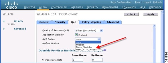
11.![]() For example, select the AVC profile Block_Youtube from the drop-down and click Apply.
For example, select the AVC profile Block_Youtube from the drop-down and click Apply.

Note: If Application visibility is not enabled on the WLAN, and users selects an AVC profile and Apply is clicked, this automatically enables Application visibility. But to disable Application visibility from WLAN, AVC profile, which is mapped to WLAN, should be removed first by selecting None from drop-down.
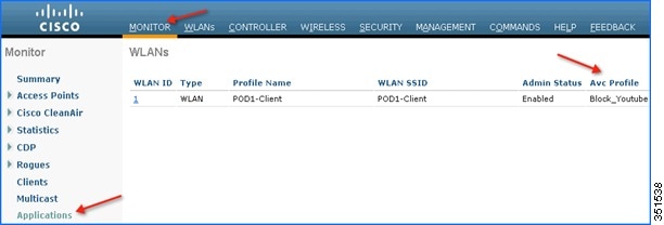
12.![]() Once AVC profiles are applied on WLAN it is also visible under Monitor > Applications. All the WLANs which has Application Visibility enabled will be displayed
Once AVC profiles are applied on WLAN it is also visible under Monitor > Applications. All the WLANs which has Application Visibility enabled will be displayed
13.![]() Now try to open www.youtube.com from wireless clients. Make sure that the client cannot play any videos on YouTube. Also try to open your Facebook account (in case you have one) and try to open any YouTube video from your Facebook account. You will observe YouTube videos cannot be played.
Now try to open www.youtube.com from wireless clients. Make sure that the client cannot play any videos on YouTube. Also try to open your Facebook account (in case you have one) and try to open any YouTube video from your Facebook account. You will observe YouTube videos cannot be played.
Because YouTube is blocked in the AVC profile and AVC profile is been mapped to WLAN, clients will not be able to access YouTube videos via browser or even via YouTube application or from any other website.
Note: If your browser was already open and running Youtube.com, refresh the browser for the AVC profile to take effect.
14.![]() Now change the AVC profile on the WLAN to test the MARK operation of the NBAR feature. Select AVC profile Mark_Http_Webex from the drop-down under QOS tab on the WLAN and click Apply.
Now change the AVC profile on the WLAN to test the MARK operation of the NBAR feature. Select AVC profile Mark_Http_Webex from the drop-down under QOS tab on the WLAN and click Apply.

15.![]() Once the AVC profiles are applied on the WLAN, it is also visible under Monitor > Applications. All the WLANs which has Application Visibility enabled will be displayed.
Once the AVC profiles are applied on the WLAN, it is also visible under Monitor > Applications. All the WLANs which has Application Visibility enabled will be displayed.

16.![]() Once the AVC profile Mark_Http_Webex is applied on the WLAN, initiate or login to your individual WebEx account (if you have one) and also initiate some HTTP connections and observe the marking for these two applications under client details. Once the AVC profile is mapped to a WLAN and if it has a rule for the MARK action, that application will get precedence as per QoS profile configured in AVC rule overriding the QoS profile configured on the WLAN.
Once the AVC profile Mark_Http_Webex is applied on the WLAN, initiate or login to your individual WebEx account (if you have one) and also initiate some HTTP connections and observe the marking for these two applications under client details. Once the AVC profile is mapped to a WLAN and if it has a rule for the MARK action, that application will get precedence as per QoS profile configured in AVC rule overriding the QoS profile configured on the WLAN.
Although the WLAN in this example is mapped to the default QOS profile SILVER, the AVC profile has been created and mapped to this WLAN to MARK application WebEx and HTTP with a different QOS profile. Traffic for application WebEx will be marked with PLATINUM profile and traffic for all HTTP application will be marked with BRONZE profile. Rest of the applications that do not match any rules in the AVC profile; will be marked with QOS profile configured on WLAN i.e. SILVER in this example.
17.![]() To see the markings stats for client traffic, navigate to Monitor > Clients and then click any individual client MAC entry listed on that page.
To see the markings stats for client traffic, navigate to Monitor > Clients and then click any individual client MAC entry listed on that page.

After clicking on the individual client MAC entry listed on the above page, the client details page will open which will have two tabs; one for general information and another tab with name AVC Statistics. Click the AVC Statistics tab and further click the UPSTREAM tab to notice the MARKING operation of the AVC profile.
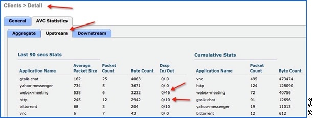
Notice the above output and make sure the WebEx application is getting OUT DSCP value as 46 because the WebEx application is been configured with Platinum QOS profile and HTTP application is getting OUT DSCP value as 10 because the HTTP application is been configured with Bronze profile.
Configure NBAR NetFlow Monitor
A NetFlow monitor can also be configured on the WLC to collect all the stats generated on a WLC and these can be exported to the NetFlow collector. In the following example, Cisco Performance Application Manager (PAM) is shown as being used as a NetFlow collector. PAM is a licensed application running on Cisco Prime Infrastructure.
1.![]() Add NetFlow Exporter first on WLC by configuring Exporter (NetFlow collector). In this example Cisco PAM is an exporter. It collects all the NetFlow stats generated by the WLC. To add an exporter in the WLC, navigate to Wireless > NetFlow > Exporter, then click New.
Add NetFlow Exporter first on WLC by configuring Exporter (NetFlow collector). In this example Cisco PAM is an exporter. It collects all the NetFlow stats generated by the WLC. To add an exporter in the WLC, navigate to Wireless > NetFlow > Exporter, then click New.
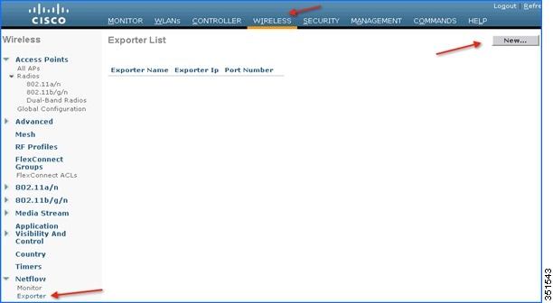
2.![]() Enter the details of PAM, Exporter IP, as an example below 10.10.105.3 and Port Number as 9991 which will collect all the NetFlow stats generated by the WLC and then click Apply.
Enter the details of PAM, Exporter IP, as an example below 10.10.105.3 and Port Number as 9991 which will collect all the NetFlow stats generated by the WLC and then click Apply.


Note: Only one exporter can be added in the WLC.
3.![]() After adding Exporter details on the WLC i.e. PAM server, a monitor needs to be created which will store the NetFlow stats and export the same to the PAM server. To create a Monitor, navigate to Wireless > NetFlow > Monitor, then click New.
After adding Exporter details on the WLC i.e. PAM server, a monitor needs to be created which will store the NetFlow stats and export the same to the PAM server. To create a Monitor, navigate to Wireless > NetFlow > Monitor, then click New.
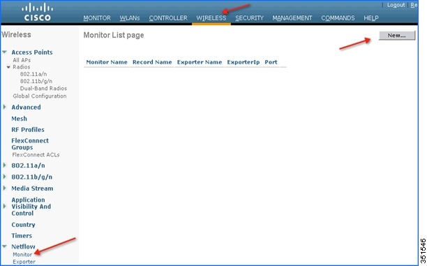
4.![]() Enter any name to create the Monitor entry on WLC and click Apply.
Enter any name to create the Monitor entry on WLC and click Apply.

5.![]() Once applied, the Monitor entry will be created which will need to be further mapped to the Exporter created in step 2.
Once applied, the Monitor entry will be created which will need to be further mapped to the Exporter created in step 2.

Note: Only one Monitor entry can be added in the WLC.
6.![]() Click the Monitor entry and map it to the Exporter entry, which is Cisco PAM. The exporter name drop-down list the “Exporter” entry that is created above. Record name “ipv4_client_app_flow_record” is auto generated by WLC, which records all the NBAR statistics and exports to the Cisco PAM. Select this record entry in the record name drop-down and click Apply.
Click the Monitor entry and map it to the Exporter entry, which is Cisco PAM. The exporter name drop-down list the “Exporter” entry that is created above. Record name “ipv4_client_app_flow_record” is auto generated by WLC, which records all the NBAR statistics and exports to the Cisco PAM. Select this record entry in the record name drop-down and click Apply.


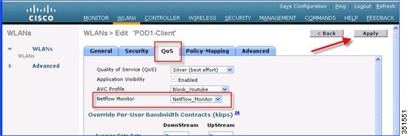
7.![]() Once the Monitor entry is created and the Exporter entry is mapped to the same, it should be mapped to the WLAN. To map the exporter entry to WLAN, click WLANs and then click the specific WLAN ID. Click the QOS tab and choose the Monitor entry created above from the NetFlow Monitor drop-down and then click Apply on the WLAN Edit page.
Once the Monitor entry is created and the Exporter entry is mapped to the same, it should be mapped to the WLAN. To map the exporter entry to WLAN, click WLANs and then click the specific WLAN ID. Click the QOS tab and choose the Monitor entry created above from the NetFlow Monitor drop-down and then click Apply on the WLAN Edit page.
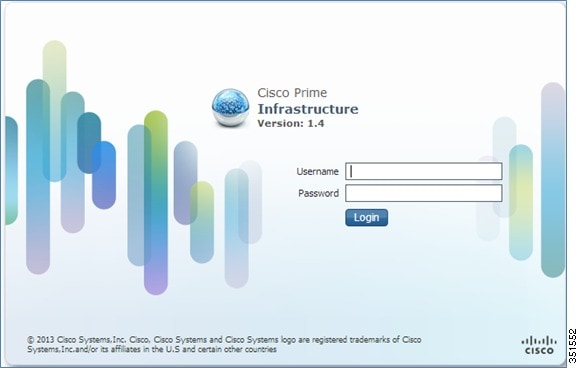
8.![]() Now open a new tab on the browser and login to the Cisco Prime Infrastructure Server to add individual WLCs to PAM.
Now open a new tab on the browser and login to the Cisco Prime Infrastructure Server to add individual WLCs to PAM.
9.![]() Add the WLC in Cisco PAM. To add WLC into Cisco PAM, login to Cisco PAM and navigate to Operate > Device Work Center, then click Add Device in the Lifecycle Theme.
Add the WLC in Cisco PAM. To add WLC into Cisco PAM, login to Cisco PAM and navigate to Operate > Device Work Center, then click Add Device in the Lifecycle Theme.

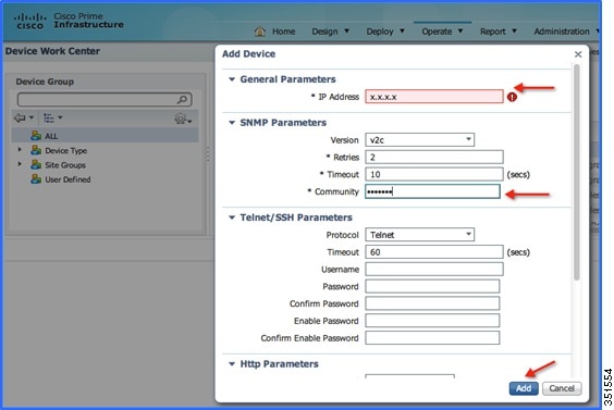
10.![]() Enter the details of individual WLC i.e. WLC Management IP Address (Example WLC-POD4 = 10.10.40.2) and Community String as public and then click Add.
Enter the details of individual WLC i.e. WLC Management IP Address (Example WLC-POD4 = 10.10.40.2) and Community String as public and then click Add.
11.![]() Once the WLC is added, start some traffic from wireless clients. You can view the number of clients per WLAN and usage per client. To see the usage by clients, navigate to Home > Detail Dashboards > Application. Now filter the Application Box as All, Site as Unassigned, and Network Aware as Wireless > PODX-Client and then click Go.
Once the WLC is added, start some traffic from wireless clients. You can view the number of clients per WLAN and usage per client. To see the usage by clients, navigate to Home > Detail Dashboards > Application. Now filter the Application Box as All, Site as Unassigned, and Network Aware as Wireless > PODX-Client and then click Go.
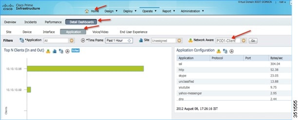
Note: You can see the number of clients on WLAN “POD1-Client” which is filtered under Network Aware. Also, in same screen, you can see the applications used by both the clients.
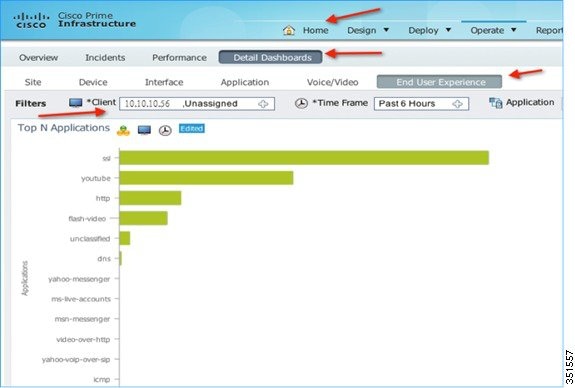
12.![]() To see the application usage by a particular client, navigate to Home > Detail Dashboards > End User Experience > Under Filter and then select the client IP.
To see the application usage by a particular client, navigate to Home > Detail Dashboards > End User Experience > Under Filter and then select the client IP.
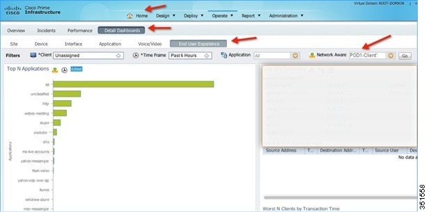
13.![]() To see application usage per WLAN, navigate to Home > Detail Dashboards > End User Experience > Under Filter and then select the Network Aware as WLAN i.e. POD1-Client in this example. Click GO.
To see application usage per WLAN, navigate to Home > Detail Dashboards > End User Experience > Under Filter and then select the Network Aware as WLAN i.e. POD1-Client in this example. Click GO.
AVC—Phase 3 in CUWN Release 8.0
In this release, a lot of enhancement has been made on the AVC feature set that includes the following:
■![]() AAA AVC Profile override for clients.
AAA AVC Profile override for clients.
■![]() Application rate limiting per-user on WLAN.
Application rate limiting per-user on WLAN.
■![]() Integration of AVC profiles to the Local Policy classification per user and per device.
Integration of AVC profiles to the Local Policy classification per user and per device.
■![]() AVC Directional QoS DSCP Marking for Upstream and Downstream traffic.
AVC Directional QoS DSCP Marking for Upstream and Downstream traffic.
■![]() Support for 1105 applications with Protocol Pack 9.0 and NBAR Engine release 3.1.
Support for 1105 applications with Protocol Pack 9.0 and NBAR Engine release 3.1.
AAA AVC Profile Override for Clients
As mentioned above in releases 7.4, 7.5, and 7.6, the AVC Profile is configured on a WLAN and all clients connected to that WLAN inherit the same AVC profile. The value proposition to allow for the AAA AVC profile override is to enable different clients (logging in as different users) to obtain different AVC profiles even though they are connected to the same WLAN.
The AAA attribute for a client or user profile can be configured on AAA servers, for example, Cisco ACS or ISE. The AAA attribute is defined as a generic Cisco AV Pair and can be defined as a string and value pair in AAA. This attribute is processed during L2/L3 Authentication by the WLC and the same is overridden by what is configured on the WLAN.
Steps to Configure Application Visibility Per User Role
1.![]() Create/Configure a WLAN with L2 Security set for WPA2/802.1x authentication. Assuming that the user/administrator has already configured the AAA server for dot1x authentication, choose the AAA server from the Authentication Servers drop-down list and click Apply.
Create/Configure a WLAN with L2 Security set for WPA2/802.1x authentication. Assuming that the user/administrator has already configured the AAA server for dot1x authentication, choose the AAA server from the Authentication Servers drop-down list and click Apply.
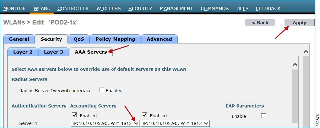
Click the Advanced tab and enable “AAA Override” as shown below.

2.![]() To enable Application Visibility, click the WLAN ID and in the QoS tab, check the Enabled check box for Application Visibility. Click Apply.
To enable Application Visibility, click the WLAN ID and in the QoS tab, check the Enabled check box for Application Visibility. Click Apply.

AAA Configuration for AVC Profile
The AAA AVC Profile is defined as a Cisco AV Pair. The string is defined as avc-profile-name and this has to be configured for any AVC profile existing on the WLC.
1.![]() To demonstrate the AVC profile being applied per user through AAA server, create AVC profiles by navigating to Wireless > Application Visibility And Control > AVC Profiles and click New. In this setup/example, we created a teacher-AVC and student-AVC. We will mark specific traffic (YouTube and so on) for user/role teacher and block/drop the specific application/traffic (YouTube, Facebook and so on) for user/role student. You can create your own AVC profiles according to your network requirements.
To demonstrate the AVC profile being applied per user through AAA server, create AVC profiles by navigating to Wireless > Application Visibility And Control > AVC Profiles and click New. In this setup/example, we created a teacher-AVC and student-AVC. We will mark specific traffic (YouTube and so on) for user/role teacher and block/drop the specific application/traffic (YouTube, Facebook and so on) for user/role student. You can create your own AVC profiles according to your network requirements.
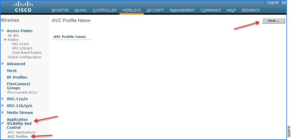
2.![]() Enter the AVC profile name and click Apply. Similarly, create another profile.
Enter the AVC profile name and click Apply. Similarly, create another profile.

3.![]() The AVC profile is created and you can view the above created profile, which can be clicked to create rules to take drop/mark/Rate Limit action from the GUI. A maximum of 16 AVC profiles can be created on the WLC.
The AVC profile is created and you can view the above created profile, which can be clicked to create rules to take drop/mark/Rate Limit action from the GUI. A maximum of 16 AVC profiles can be created on the WLC.
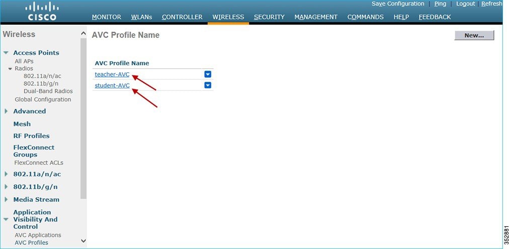
4.![]() After creating the AVC profiles, you can click any profile name and create rules for individual profiles. A maximum of 32 rules can be configured in each profile. Rules can be configured to take any of the 3 actions, that is, DROP, MARK, and RATE LIMIT. If no rule is configured for any application, the default action will be “Allow” with the QOS policy configured on the WLAN. To create rules for a profile, go to Wireless > Application Visibility And Control > AVC Profiles, and then click any Profile.
After creating the AVC profiles, you can click any profile name and create rules for individual profiles. A maximum of 32 rules can be configured in each profile. Rules can be configured to take any of the 3 actions, that is, DROP, MARK, and RATE LIMIT. If no rule is configured for any application, the default action will be “Allow” with the QOS policy configured on the WLAN. To create rules for a profile, go to Wireless > Application Visibility And Control > AVC Profiles, and then click any Profile.


Note: WLC is capable of classifying 1105 applications with Protocol Pack 11.0 and gives an option to take action. To take an action on any application, the administrator has to select the application group first to which that application belongs, which will filter the list of applications for that application group only. The reason for this implementation is all 1105 applications cannot be displayed in a single drop-down. The administrator is also flexible while configuring Action as MARK to choose the Differentiated Services Code Point (DCSP) value as Custom instead of selecting “Platinum/Gold/Silver/Bronze”. Once Custom is selected as the DSCP value, a text field will be visible where the admin can enter the custom DSCP value in the range of 0 - 63.
Prior to Release 8.0, the DSCP Marking is only applied bi-directionally for traffic. But in Release 8.0, an extra configuration parameter of “Direction” is available where marking can be specified with respect to direction, that is, Upstream or Downstream as shown below.

5.![]() Once the appropriate Marking is selected, click Apply. The action rule will be created and is displayed as captured in the below screen. You can add more rules under the same AVC profile on the same page. A maximum of 32 rules can be configured in a single AVC profile.
Once the appropriate Marking is selected, click Apply. The action rule will be created and is displayed as captured in the below screen. You can add more rules under the same AVC profile on the same page. A maximum of 32 rules can be configured in a single AVC profile.
Another rule can be configured under the same AVC profile to MARK traffic with a different QoS profile or custom DSCP value with a specific direction.
Here, we configured Netflix and YouTube to be marked for the AVC profile “teacher-AVC” with DSCP 34 (Gold) with the direction set to Bidirectional and Upstream, respectively.

6.![]() Similarly, the following example displays another AVC profile (student-AVC) for a different role type, which is student in our setup and is configured to drop Facebook, YouTube, and BitTorrent traffic.
Similarly, the following example displays another AVC profile (student-AVC) for a different role type, which is student in our setup and is configured to drop Facebook, YouTube, and BitTorrent traffic.

7.![]() Now, assume that the user/administrator has already configured the AAA server (ISE/ACS/Open Radius) with users (teacher and student), devices (WLC), and Authorization Profiles. To configure the AAA Server to match the profile for the AVC set on the WLC, from ISE main menu bar, go to Policy > Policy Elements > Results > Authorization > Authorization Profiles. Here, you see the configured profiles (Student and Teacher) displayed in the example screenshot below.
Now, assume that the user/administrator has already configured the AAA server (ISE/ACS/Open Radius) with users (teacher and student), devices (WLC), and Authorization Profiles. To configure the AAA Server to match the profile for the AVC set on the WLC, from ISE main menu bar, go to Policy > Policy Elements > Results > Authorization > Authorization Profiles. Here, you see the configured profiles (Student and Teacher) displayed in the example screenshot below.
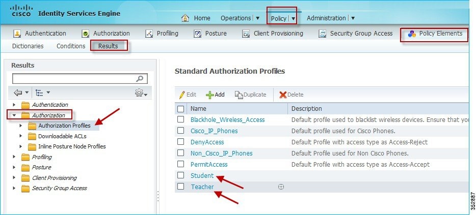
8.![]() Click the authorization profile which you created for the role Teacher, and under Advanced Attributes Settings, configure AVC Profile Name by adding cisco-av-pair=avc-profile-name=The AVC profile name created on the WLC, as shown below.
Click the authorization profile which you created for the role Teacher, and under Advanced Attributes Settings, configure AVC Profile Name by adding cisco-av-pair=avc-profile-name=The AVC profile name created on the WLC, as shown below.
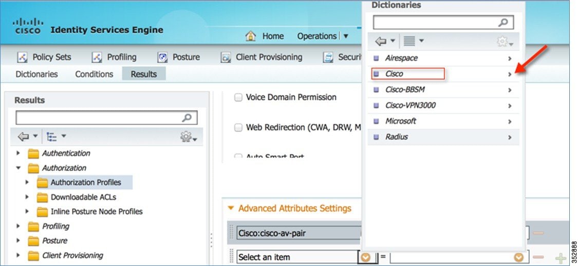
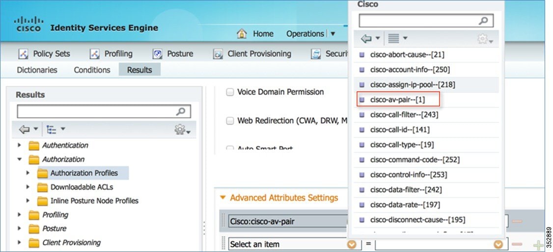
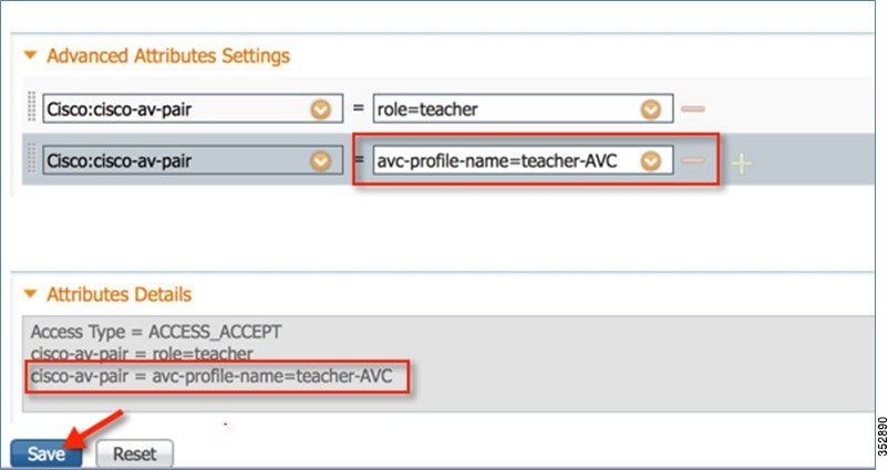
If you are using the Cisco ACS, go to Policy Elements > Authorization and Permissions > Network Access > Authorization Profiles. Add cisco-av-pair to match the string value avc-profile-name=The AVC profile name created on the WLC.
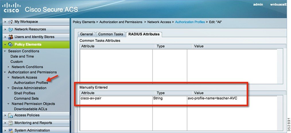
Similarly, configure the Authorization profile for student as well. Once configuration is done, you can connect a wireless client to the 802.1x WLAN with teacher credentials. You will be able to access Netflix and YouTube.
When the wireless client (with role student) connects to the same 802.1x WLAN, the client cannot play any videos on YouTube. Also, if the client tries to access a Facebook page and tries to open any YouTube video from the Facebook account, the YouTube video will not be played.
Because both YouTube and Facebook are blocked in the AVC profile for Student-AVC, therefore clients with student role will not be able to access YouTube videos via a browser or even via a YouTube application or from any other website nor they can access Facebook.
On the other hand, when the client logs in with Teacher credentials, the traffic is just marked and no application is dropped.
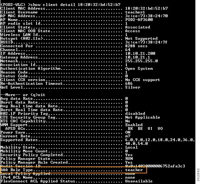
To verify if the policy is applied, from the WLC CLI prompt, run the following command:
show client detail mac_address, then scroll down to see the applied profile.
Application Rate Limiting Through AVC
In this release, we can configure only 3 applications for rate limiting which can be done from the WLC CLI through the following command:
(WLC) >config avc profile <prof-name> {add|remove} rule application <app-name> {drop|mark <dscp-value>|ratelimit <avg_rate> <burst_rate>}
Note: The minimum ratelimit value can be set from minimum 0 Kbps to maximum 2147483647 Kbps.
The configuration example below is performed on the profile “student-AVC” when using the BitTorrent application:
(WLC) >config avc profile student-AVC rule add application bittorrent ratelimit 150 500
Similarly, from the WLC GUI, the Rate Limiting can be configured by selecting the application on which the user wants to apply Rate Limit and from the Action drop-down list, choose Rate-Limit.
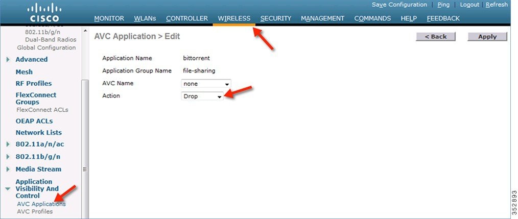
This brings up an option for the user to configure the average and burst rates for the desired application that the user needs to rate limit. The user can assign any value in Kbps from 0 to 2147483647. Once the Rate-Limit is set, the user can choose the “AVC Name” on which he wants to apply the Rate Limit and click Apply.
In this example, we are rate limiting the BitTorrent application with the average rate set to 150 Kbps and burst rate set to 500 Kbps and applying this to the AVC profile “student-AVC”.

The BitTorrent application displays ratelimit in the Action column with Rate Limit average and burst rate values.

NBAR Facts (AVC Phase 3)
■![]() NBAR Engine 13 and PP 11.0 can support 1105 different applications.
NBAR Engine 13 and PP 11.0 can support 1105 different applications.
■![]() Three actions DROP, MARK and RATE LIMIT is possible on any classified application.
Three actions DROP, MARK and RATE LIMIT is possible on any classified application.
■![]() A maximum of 16 AVC profiles can be created on the WLC.
A maximum of 16 AVC profiles can be created on the WLC.
■![]() Each AVC profile can be configured with a maximum of 32 rules.
Each AVC profile can be configured with a maximum of 32 rules.
■![]() The same AVC profile can be mapped to multiple WLANs. But one WLAN can have only one AVC profile.
The same AVC profile can be mapped to multiple WLANs. But one WLAN can have only one AVC profile.
■![]() Only one NetFlow exporter and monitor can be configured on the WLC.
Only one NetFlow exporter and monitor can be configured on the WLC.
■![]() NBAR statistics are displayed only for the top 30 applications on the GUI. The CLI can be used to see all applications.
NBAR statistics are displayed only for the top 30 applications on the GUI. The CLI can be used to see all applications.
■![]() NBAR is supported on WLANs configured for central switching only.
NBAR is supported on WLANs configured for central switching only.
■![]() If the AVC profile mapped to the WLAN has a rule for MARK action, that application will get precedence as per QOS profile configured in the AVC rule overriding the QOS profile configured on the WLAN.
If the AVC profile mapped to the WLAN has a rule for MARK action, that application will get precedence as per QOS profile configured in the AVC rule overriding the QOS profile configured on the WLAN.
■![]() Directional Marking can only be applied either Bidirectional, Upstream or Downstream on a particular application.
Directional Marking can only be applied either Bidirectional, Upstream or Downstream on a particular application.
■![]() Currently, Rate Limit can only be applied to three applications.
Currently, Rate Limit can only be applied to three applications.
■![]() Any application that is not supported/recognized by the NBAR engine on the WLC is captured under bucket of UNCLASSFIED traffic.
Any application that is not supported/recognized by the NBAR engine on the WLC is captured under bucket of UNCLASSFIED traffic.
■![]() IPv6 traffic cannot be classified.
IPv6 traffic cannot be classified.
■![]() AAA override of AVC profiles is supported in 8.0 release.
AAA override of AVC profiles is supported in 8.0 release.
■![]() The AVC profile can be configured per WLAN and applied per user basis.
The AVC profile can be configured per WLAN and applied per user basis.
AVC Profiles Attached to Local Policies
In Release 8.0, an AVC profile can be mapped to a local policy for a client with a particular device type. Ensure that each local policy can be configured with a different AVC/mDNS profile name based on the AAA override to restrict the policy from being able to use the services not allowed by the profile on the same WLAN.
Introduction to Profiling and Policy Engine on the WLC
Cisco currently offers a rich set of features which provide device identification, onboarding, posture, and policy, through ISE. This new feature on the WLC does the profiling of devices based on protocols such as HTTP, DHCP, and so on to identify the end devices on the network. The user can configure the device-based policies and enforce per user or per device policy on the network. The WLC will also display statistics based on per user or per device end points and policies applicable per device.
With BYOD (Bring your own device), this feature has an impact on understanding the different devices on the network. With this, BYOD can be implemented on a small scale within the WLC itself.
Scope and Objectives
In this section, the user will be configuring and implementing Profiling and Policy on a Cisco WLC running AireOS 8.0 code.
The profiling and policy enforcement will be configured as two separate components. The configuration on the WLC is based on defined parameters specific to clients joining the network. The policy attributes which are of interest are:
a.![]() Role—Role defines the user type or the user group the user belongs to.
Role—Role defines the user type or the user group the user belongs to.
For example: Student or Employee
b.![]() Device—Device defines the type of device.
Device—Device defines the type of device.
For example: Windows machine, Smart phone, Apple device such as iPad, iPhone and so on.
c.![]() Time of day—Allows configuration to be defined at what time of the day end-points are allowed on the network.
Time of day—Allows configuration to be defined at what time of the day end-points are allowed on the network.
d.![]() EAP Type—Checks what EAP method the client is getting connected to.
EAP Type—Checks what EAP method the client is getting connected to.
The above parameters are configurable as policy match attributes. Once the WLC has a match corresponding to the above parameters per end-point, the policy enforcement comes into picture. Policy enforcement will be based on session attributes such as:
■![]() AVC profile (added in 8.0 release)
AVC profile (added in 8.0 release)
■![]() mDNS profile (added in 8.0 release)
mDNS profile (added in 8.0 release)
The user can configure these policies and enforce end-points with specified policies. The wireless clients will be profiled based on the MAC OUI, DHCP, and HTTP user agent (valid Internet required for successful HTTP profiling). The WLC uses these attributes and predefined classification profiles to identify the device.
Profiling and Policy Configuration
1.![]() To configure device profiling on a WLAN, go to the specific WLAN on which you want to implement Native profiling and policy and click the Advanced tab. Disable Allow AAA Override if it is enabled. In the DHCP area, check the Required check box for DHCP Addr. Assignment.
To configure device profiling on a WLAN, go to the specific WLAN on which you want to implement Native profiling and policy and click the Advanced tab. Disable Allow AAA Override if it is enabled. In the DHCP area, check the Required check box for DHCP Addr. Assignment.

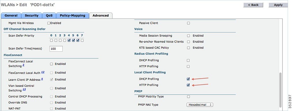
2.![]() After enabling the DHCP required option, scroll down and in the Local Client Profiling area, enable DHCP Profiling and HTTP Profiling if they are not enabled and click Apply.
After enabling the DHCP required option, scroll down and in the Local Client Profiling area, enable DHCP Profiling and HTTP Profiling if they are not enabled and click Apply.
Creating Policies on the WLAN from the WLC GUI
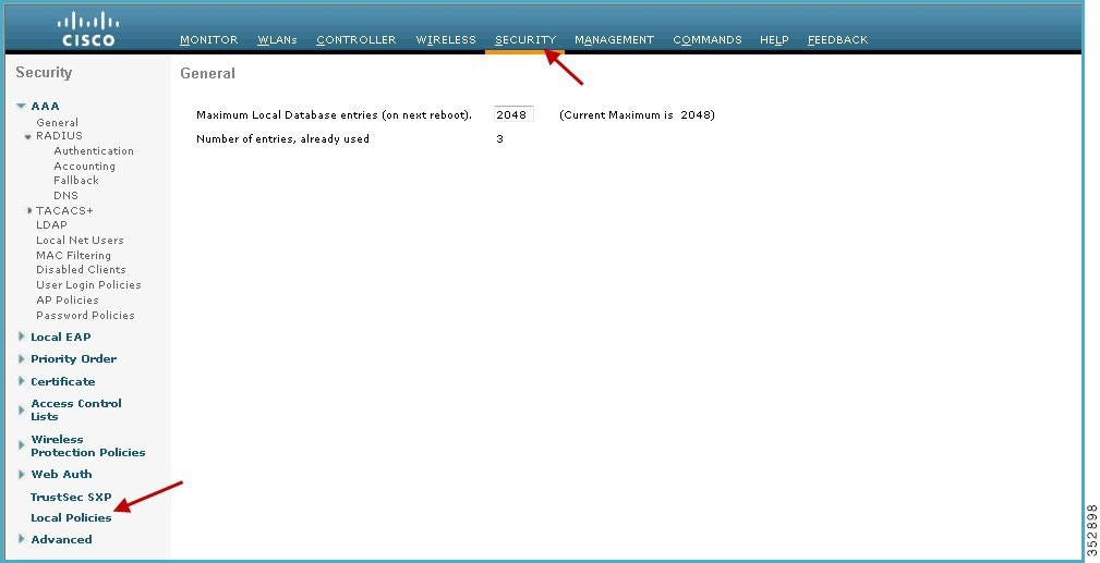
3.![]() Once Profiling is configured, we can move on to create Local policies and apply them on the WLAN. On the WLC menu bar, go to Security > Local Policies, which will take you to the Policy List.
Once Profiling is configured, we can move on to create Local policies and apply them on the WLAN. On the WLC menu bar, go to Security > Local Policies, which will take you to the Policy List.
4.![]() When in the Local Policy List, click New to create a Policy Name. In this example, teacher-LP is used as a policy name, but you can use any name to define your own policy.
When in the Local Policy List, click New to create a Policy Name. In this example, teacher-LP is used as a policy name, but you can use any name to define your own policy.

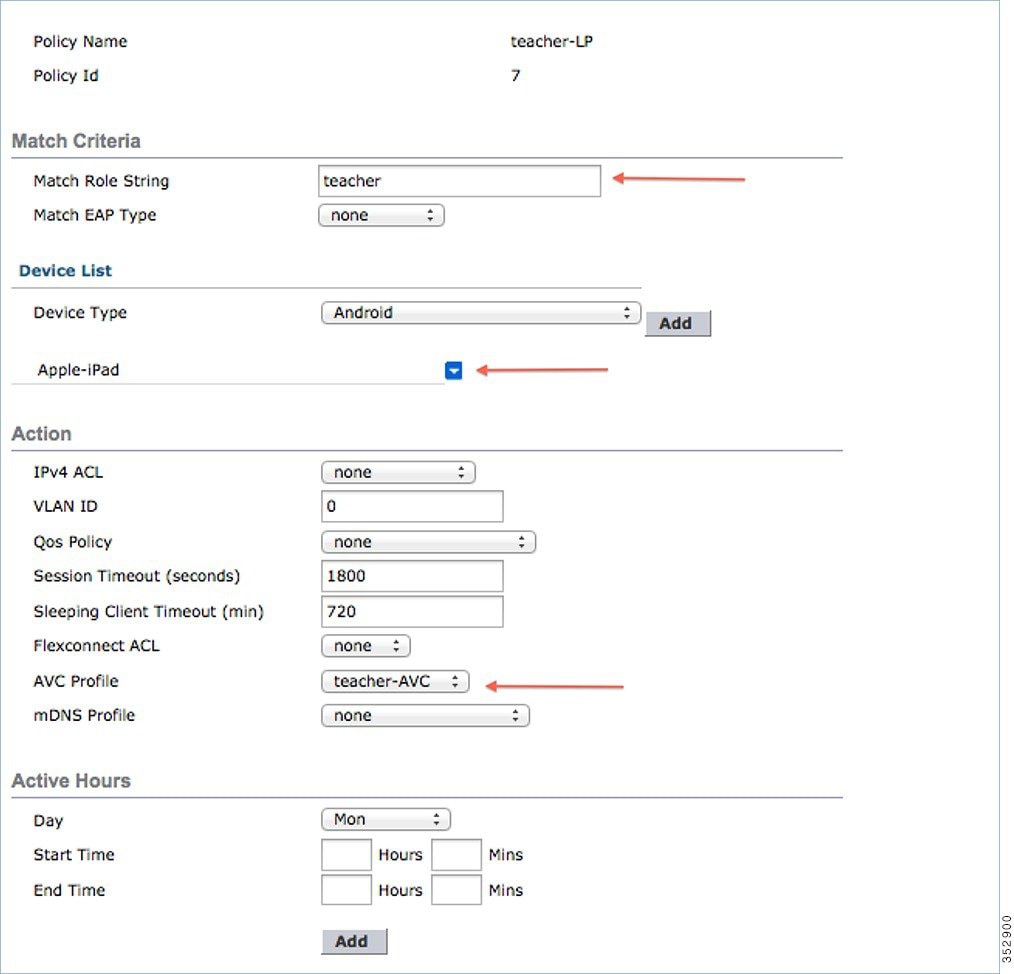
Once policy name is configured, you can create policies to match a Role, EAP Type, and Device Type. Also, you can define the required actions related to the Match criteria.
Here, in our setup we use User Role and Device Type to Match Criteria, but you can use any other type if required.
Note: Make sure Match Role string is the same as AAA defined role name. In this example, it is configured as teacher.
5.![]() Enter User Role and click Apply. Here the role name “teacher” is used as an example.
Enter User Role and click Apply. Here the role name “teacher” is used as an example.
6.![]() To apply the policy based on a user device, in the Device List area, from the Device Type drop-down list, choose the device type on which you want to enforce the policy and then click Add.
To apply the policy based on a user device, in the Device List area, from the Device Type drop-down list, choose the device type on which you want to enforce the policy and then click Add.
Here, we used Apple-iPad as a device type for Match Criteria. You can add Apple-iPhone and other Apple devices as well from the Device Type drop-down list.
Note: If you do not want to match any device type then do not configure the Device Type option.
7.![]() To apply the appropriate action, choose from the parameters under the Action area to enforce the policy. Select the AVC profile that should be defined in the last section.
To apply the appropriate action, choose from the parameters under the Action area to enforce the policy. Select the AVC profile that should be defined in the last section.
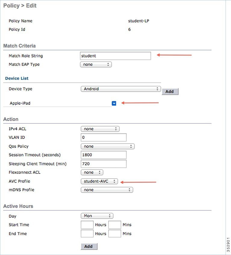
8.![]() User can create more than one Local policy and apply it for student as “student-LP”.
User can create more than one Local policy and apply it for student as “student-LP”.
Note: Ensure that the Match Role String is the same as the defined role name on the AAA/Radius Server.
To apply the policy based on a user device, in the Device List area, from the Device Type drop-down list, choose the device type (Apple-iPad) on which you want to enforce the policy and then click Add.
To apply the appropriate action, choose from the parameters under the Action area to enforce the Policy. Select the AVC profile (student-AVC) that should be defined in the last section.
9.![]() Create a default local policy for any other device.
Create a default local policy for any other device.
If no other ACL is applied in the Local policy, then any other device, other than Apple-iPad, will be able to access the applications because the final filter function of all policies is Allow all.
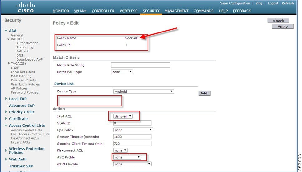
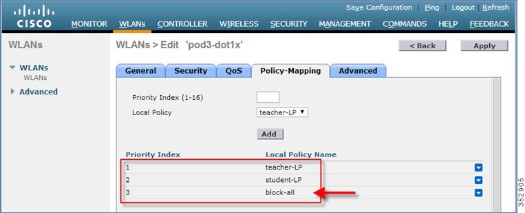
In order to block all applications on all devices except Apple-iPad, create a deny all ACL and apply it on the Local Policy and then apply that policy on the WLAN as the last resort. See the configuration examples in the screenshots below.
Create an ACL to deny all IPv4 flow.

Create a Local Policy Block-all and apply the deny all ACL to it, do not choose any devices roles or profiles.
Mapping Policy on WLAN
1.![]() Go to WLANs from the WLC menu bar and click the WLAN ID on which you want the policy to be implemented. From the WLAN edit menu, click the Policy-Mapping tab.
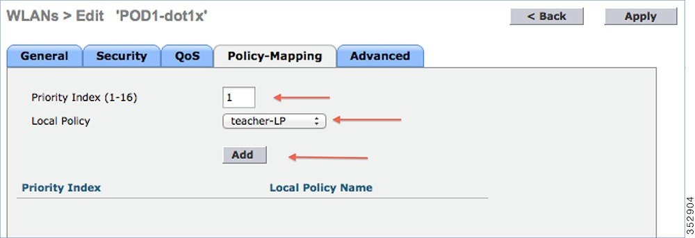
Go to WLANs from the WLC menu bar and click the WLAN ID on which you want the policy to be implemented. From the WLAN edit menu, click the Policy-Mapping tab.
Set the Priority index to any value from 1-16. From the Local Policy drop-down list, choose the policy which you have already created. To apply the policy on the WLAN, click Add. The policy will be mapped to the WLAN and can be seen under Policy Name.
2.![]() Add the appropriate policies to Policy-Mapping under WLAN.
Add the appropriate policies to Policy-Mapping under WLAN.
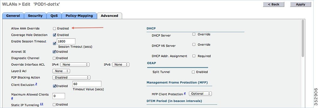
3.![]() In the Advanced tab, disable Allow AAA Override if it is enabled.
In the Advanced tab, disable Allow AAA Override if it is enabled.
4.![]() Check if the AAA role is configured properly, that is, role name on the AAA server should match the role string defined in the local policy. The example below is from the Cisco ISE server and Cisco ACS.
Check if the AAA role is configured properly, that is, role name on the AAA server should match the role string defined in the local policy. The example below is from the Cisco ISE server and Cisco ACS.
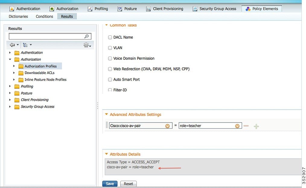
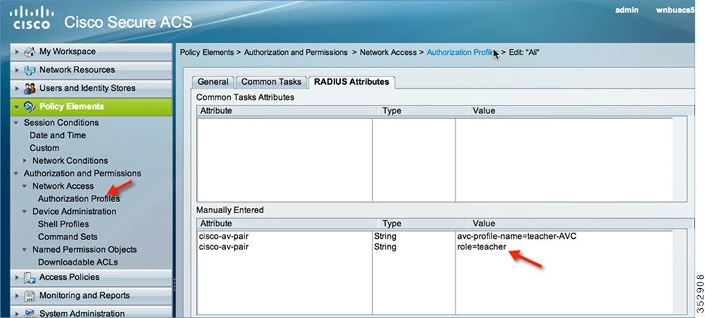
Once the client associates to SSID with teacher credentials through Apple iPad, it should be able to access Internet and different applications per its AVC profile configuration. If the user tries to connect from any device other than Apple iPad, then it will not be able to access the Internet.
To verify if the policy is applied from the WLC GUI, go to Monitor > Clients, and then click the Client MAC address.
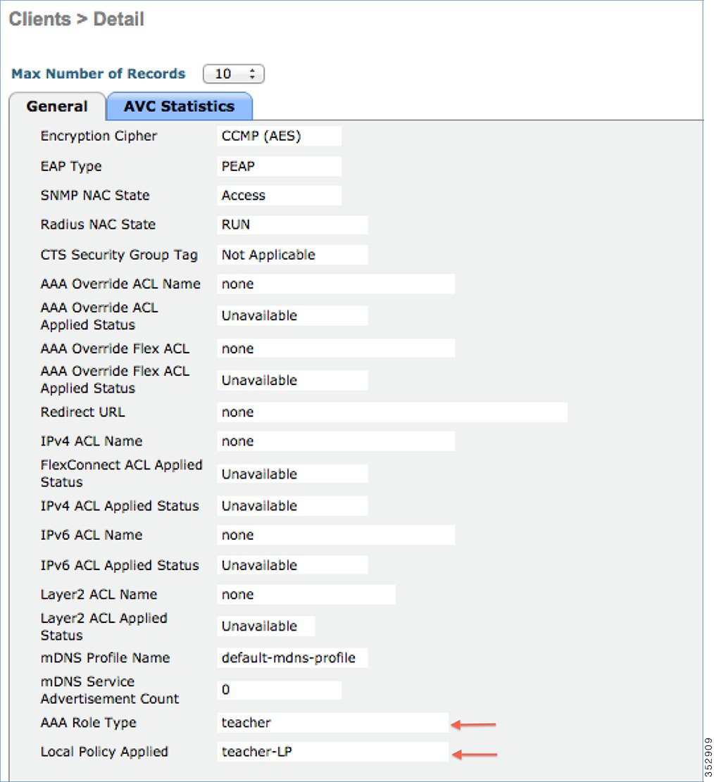
To verify if the policy is applied from WLC CLI prompt, run the following command:
show client detail mac_address and then scroll down to the end to see the applied profile.
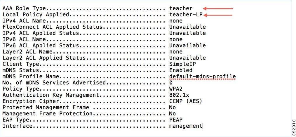
To verify if the AVC policy is applied from the WLC:
AVC Profile Name:............................................. teacher-AVC
Try to connect SSID with student credentials, you should see another policy applied (student-AVC) and if the client device is not an Apple-iPad, the user will not be able to access the network.
Native Profiling Limitations
■![]() Wired clients behind the WGB will not be profiled and policy action will not be done.
Wired clients behind the WGB will not be profiled and policy action will not be done.
■![]() Only 16 policies per WLAN can be configured, and globally 64 policies will be allowed.
Only 16 policies per WLAN can be configured, and globally 64 policies will be allowed.
■![]() Policy action will be done after L2 authentication is complete or after L3 authentication or when the device sends http traffic and gets the device profiled. Due to which certain scenarios profiling and policy actions will happen more than once per client.
Policy action will be done after L2 authentication is complete or after L3 authentication or when the device sends http traffic and gets the device profiled. Due to which certain scenarios profiling and policy actions will happen more than once per client.
■![]() This release will support only IPv4 clients to be profiled.
This release will support only IPv4 clients to be profiled.
■![]() No support for WGB wired clients for profiling because http profiling is not supported on WGB wired clients.
No support for WGB wired clients for profiling because http profiling is not supported on WGB wired clients.
Summary
■![]() By default, profiling is disabled on all WLANs
By default, profiling is disabled on all WLANs
■![]() Each WLAN can have mapped profiling policies configured.
Each WLAN can have mapped profiling policies configured.
■![]() Each Policy can have matching Role Type, Device Type, EAP type configured and an associated policy index mapped.
Each Policy can have matching Role Type, Device Type, EAP type configured and an associated policy index mapped.
■![]() The policy index signifies which policy needs to be matched first.
The policy index signifies which policy needs to be matched first.
■![]() The corresponding policy name will be deduced from the policy Index.
The corresponding policy name will be deduced from the policy Index.
■![]() The policy matching will exit at the first policy match and the corresponding policy action attributes will be set per client.
The policy matching will exit at the first policy match and the corresponding policy action attributes will be set per client.
■![]() The order of applying the policies per client will be based on the security type.
The order of applying the policies per client will be based on the security type.
AVC in FlexConnect Mode
For more information, see http://www.cisco.com/c/en/us/td/docs/wireless/controller/technotes/8-1/Flex-7500/Flex_7500_DG.html#pgfId-131717.
Protocol Pack and NBAR Engine Update
Up to release 8.2, NBAR Engine (16) is integrated in WLC for centralized AVC support, which supports Protocol Pack (PP) up to version-12. In release 8.2, the new and improved NBAR Engine 23 and Protocol Pack 14 are introduced. The new versions allow customers to classify 1273 application like Netflix, Jabber, Bittorrent and YouTube and other a lot more reliably with higher precision and less impact on the controller performance. It is also important to note that Protocol Pack 14 requires NBAR engine 23 and will not work with the previous NBAR released version in the prior WLC releases. When PP version 15 is released and posted on CCO, it will operate with NBAR engine 23.

Netflow Supprt in release 8.2
An IP traffic flow is a sequence of packets passing through a network device with common attributes like source and destination IP address & transport ports, direction, etc. Additional common attributes for wireless flow are SSID, AP MAC. These packets with common attributes are aggregated into flows and exported to the Netflow Collectors. Prior to relase 8.2, controller exported Netflow data was analyzed only by PI (Prime Infrastructure) and wasn't compatible with any third party Netflow collectors.
In release 8.2 nenhanced Netflow records exporter is introduced. New Netflow v9 is sending 17 different data records ( as defined in RFC 3954) to the External 3rd Party Netflow collector such as Lancope and others. Support for the Enhanced Flow Record Data Export was added on the WLC 5520, 8510 and 8540.
Prior to release 8.2 Netflow feature available on the controller sends only the IP address of the client, SSID and Application statistics. While this helps for compatible Netflow collectors like Cisco Prime to show the application statistics, it does not provide the full 5 tuple flow information and is also not compatible with many 3rd party Netflow collectors who expect 5 tuples.
The current netflow record prior to release 8.2 that WLC exports support only the following fields
The newly introduced flow record exporter in the release 8.2 supports the following flow data records
Netflow Deployment Considerations
■![]() WLC supports only one monitor and exporter.
WLC supports only one monitor and exporter.
■![]() WLC will support only one type of Netflow record globally per controller.
WLC will support only one type of Netflow record globally per controller.
■![]() Flow records are exported directly and will not be shown on the controller.
Flow records are exported directly and will not be shown on the controller.
■![]() Application visibility statistics present today will continue on the controller.
Application visibility statistics present today will continue on the controller.
■![]() Change to monitor parameters will required the WLAN to be disabled and enabled.
Change to monitor parameters will required the WLAN to be disabled and enabled.
■![]() The new record will be supported on 8510, 5520 and 8540 controllers only.
The new record will be supported on 8510, 5520 and 8540 controllers only.
■![]() 2500, 5508, 7500 and WiSM2 controllers will not be supported.
2500, 5508, 7500 and WiSM2 controllers will not be supported.
■![]() Netflow statistics are sent at an interval of 30 seconds (Not user configurable. Current value is 90 seconds).
Netflow statistics are sent at an interval of 30 seconds (Not user configurable. Current value is 90 seconds).
■![]() Netflow record will be sent even for the unclassified applications with new flow record.
Netflow record will be sent even for the unclassified applications with new flow record.
■![]() Netflow will be sent on enabling AVC on that WLAN.
Netflow will be sent on enabling AVC on that WLAN.
■![]() IPv6 traffic is not supported in Netflow in release 8.2.
IPv6 traffic is not supported in Netflow in release 8.2.
■![]() Netflow sending initial template will be sent from Control plane.
Netflow sending initial template will be sent from Control plane.
Obtaining Lancope Software for Evaluation Purposes (Reference)
The software is available for web download on the URL as indicated below:
https://www.lancope.com/stealthwatch-evaluation-application
1.![]() Sign up for Stealth Watch Evaluation and download the software
Sign up for Stealth Watch Evaluation and download the software

2.![]() Then download the latest "FlowCollector for Netflow Virtual Edition install OVF Files v 6.6"
Then download the latest "FlowCollector for Netflow Virtual Edition install OVF Files v 6.6"

3.![]() Use Lancope Installation Guide posted for further configuration information.
Use Lancope Installation Guide posted for further configuration information.
Netflow Configuration on the WLC
Prior to release 8.2 Netflow configuration on WLC was done by associating the fixed record ipv4_client_app_flow_record to the Netflow monitor. Now along with this we will support a new fixed record called ipv4_client_src_dst_flow_record the same will be allowed in cli and GUI at the places shown below.
Note![]() : Since only one netflow exporter is present per controller, it has to be between the old and new record formats.
: Since only one netflow exporter is present per controller, it has to be between the old and new record formats.
Configuration steps from CLI
config flow create monitor <My_Netflow_Monitor>
config flow create exporter My_Netflow_Exporter A.B.C.D port 2055
config flow add monitor My_Netflow_Monitor exporter My_Netflow_Exporter
config flow add monitor My_Netflow_Monitor record ipv4_client_src_dst_flow_record
Configuration using WebUI
Screen shots below illustrate examples of the Lancope Netflow Collector VM on the USC box with IP Address 10.10.105.22 and it is listening on UDP port 2055.
1.![]() From WLC main menu configure a Netflow Exporter by going to Wireless > Netflow > Exporter. Click New
From WLC main menu configure a Netflow Exporter by going to Wireless > Netflow > Exporter. Click New

2.![]() Configure an Exporter Name, Exporter IP and Port Number, then click Apply.
Configure an Exporter Name, Exporter IP and Port Number, then click Apply.


3.![]() Now, we will create a Flow monitor for the Netflow Exporter which we created above. Under Netflow, go to Monitor click New.
Now, we will create a Flow monitor for the Netflow Exporter which we created above. Under Netflow, go to Monitor click New.

4.![]() Create a monitor with the name "Lancope" and click Apply as shown below:
Create a monitor with the name "Lancope" and click Apply as shown below:

5.![]() Click on the created Monitor name.
Click on the created Monitor name.

6.![]() Select ' Netflow Collector ' from the Exporter Name drop down menu and choose ' ipv4_client_src_dst_flow_record ' from the Record Name list. Click Apply.
Select ' Netflow Collector ' from the Exporter Name drop down menu and choose ' ipv4_client_src_dst_flow_record ' from the Record Name list. Click Apply.

User should see the following under Wireless > Netflow > Monitor

7.![]() Browse to the WLAN on which we need to enable AVC and Netflow Monitor. From the WLAN edit parameters, go to QoS tab and check Application Visibility box. Then select the Netflow Monitor and click Apply.
Browse to the WLAN on which we need to enable AVC and Netflow Monitor. From the WLAN edit parameters, go to QoS tab and check Application Visibility box. Then select the Netflow Monitor and click Apply.

Netflow Reporting
Lancope Netflow reporting setup comprises of a flow collector and a central management console.
Lancope FlowCollector collects data from various sources (in this case Wireless Lan Controller), analyzes them, creates a profile for normal activity and generates an alarm (to the SMC) for any activity that falls outside of the normal profile.
SMC manages, coordinates, and configures different components of the system through a web browser. It offers centralized management and reporting for up to 25 flow collectors with graphical charts for visualizing traffic.
Examples below illustrate FlowCollector residing at 10.10.105.22 (configured on the WLC above) and SMC at 10.10.105.21.
1.![]() Log into SMC with username and password.
Log into SMC with username and password.

2.![]() Click on "Launch SMC" from the dashboard. It will prompt you to download the Application "l aunch_512 ". Save it locally and Launch it.
Click on "Launch SMC" from the dashboard. It will prompt you to download the Application "l aunch_512 ". Save it locally and Launch it.


3.![]() Follow the steps as shown below when pop up window appears.
Follow the steps as shown below when pop up window appears.

4.![]() Continue Loading the Stealth Watch Monitor.
Continue Loading the Stealth Watch Monitor.

5.![]() Finally Login to Lancope Collector Monitor with credentials as per your setup.
Finally Login to Lancope Collector Monitor with credentials as per your setup.

6.![]() From the dashboard, right click Exporters -> <Controller IP> -> Flows -> Flow Table to view client flows.
From the dashboard, right click Exporters -> <Controller IP> -> Flows -> Flow Table to view client flows.

7.![]() You will see multiple client flows here. You can filter the flows on various attributes by right clicking against a column name and selecting parameter/s as shown below. In the example illustrated below, WLC with IP address 10.10.10.2 is selected with Application (NBAR) attribute.
You will see multiple client flows here. You can filter the flows on various attributes by right clicking against a column name and selecting parameter/s as shown below. In the example illustrated below, WLC with IP address 10.10.10.2 is selected with Application (NBAR) attribute.
Note![]() : In order to see the flows please make sure the clients are connected to the AVC and Netflow enabled SSID.
: In order to see the flows please make sure the clients are connected to the AVC and Netflow enabled SSID.

If user is connected with dot1x credentials, they will also be visible on the Lancope flow table dashboard.

VOD Reference
Cisco AVC - Per User Application Control: http://www.youtube.com/watch?v=ESg53o3ufDQ&feature=youtu.be
Web Links and Terminology
Cisco WLAN Controller Information:
http://www.cisco.com/en/US/products/hw/wireless/products.html
http://www.cisco.com/cisco/web/support/index.html
Cisco Prime Management Software Information:
http://www.cisco.com/en/US/products/ps11686/index.html
Contact Cisco
- Open a Support Case

- (Requires a Cisco Service Contract)
 Feedback